EP2460212B1 - Anordnung zum anschliessen von elektrischen leiterbahnen an polanschlüsse von zusammengeschalteten zellen - Google Patents
Anordnung zum anschliessen von elektrischen leiterbahnen an polanschlüsse von zusammengeschalteten zellen Download PDFInfo
- Publication number
- EP2460212B1 EP2460212B1 EP10740151.5A EP10740151A EP2460212B1 EP 2460212 B1 EP2460212 B1 EP 2460212B1 EP 10740151 A EP10740151 A EP 10740151A EP 2460212 B1 EP2460212 B1 EP 2460212B1
- Authority
- EP
- European Patent Office
- Prior art keywords
- arrangement according
- encapsulation
- leadframe
- cell
- cells
- Prior art date
- Legal status (The legal status is an assumption and is not a legal conclusion. Google has not performed a legal analysis and makes no representation as to the accuracy of the status listed.)
- Not-in-force
Links
- 239000004020 conductor Substances 0.000 title claims description 11
- 238000003780 insertion Methods 0.000 claims description 3
- 230000037431 insertion Effects 0.000 claims description 3
- 238000001746 injection moulding Methods 0.000 claims description 2
- 238000005538 encapsulation Methods 0.000 claims 10
- 230000000063 preceeding effect Effects 0.000 claims 1
- 241001474791 Proboscis Species 0.000 description 6
- 238000005516 engineering process Methods 0.000 description 2
- 238000007765 extrusion coating Methods 0.000 description 2
- 239000000243 solution Substances 0.000 description 2
- 230000000087 stabilizing effect Effects 0.000 description 2
- 241001295925 Gegenes Species 0.000 description 1
- 238000005253 cladding Methods 0.000 description 1
- 238000010276 construction Methods 0.000 description 1
- 230000001419 dependent effect Effects 0.000 description 1
- 238000011161 development Methods 0.000 description 1
- 230000018109 developmental process Effects 0.000 description 1
- 238000007654 immersion Methods 0.000 description 1
- 238000002347 injection Methods 0.000 description 1
- 239000007924 injection Substances 0.000 description 1
- 239000000463 material Substances 0.000 description 1
- 238000005259 measurement Methods 0.000 description 1
- 238000004080 punching Methods 0.000 description 1
- 238000000926 separation method Methods 0.000 description 1
- 230000035939 shock Effects 0.000 description 1
- 230000006641 stabilisation Effects 0.000 description 1
- 238000011105 stabilization Methods 0.000 description 1
Images

Classifications
-
- H—ELECTRICITY
- H01—ELECTRIC ELEMENTS
- H01M—PROCESSES OR MEANS, e.g. BATTERIES, FOR THE DIRECT CONVERSION OF CHEMICAL ENERGY INTO ELECTRICAL ENERGY
- H01M50/00—Constructional details or processes of manufacture of the non-active parts of electrochemical cells other than fuel cells, e.g. hybrid cells
- H01M50/50—Current conducting connections for cells or batteries
-
- H—ELECTRICITY
- H01—ELECTRIC ELEMENTS
- H01M—PROCESSES OR MEANS, e.g. BATTERIES, FOR THE DIRECT CONVERSION OF CHEMICAL ENERGY INTO ELECTRICAL ENERGY
- H01M50/00—Constructional details or processes of manufacture of the non-active parts of electrochemical cells other than fuel cells, e.g. hybrid cells
- H01M50/50—Current conducting connections for cells or batteries
- H01M50/502—Interconnectors for connecting terminals of adjacent batteries; Interconnectors for connecting cells outside a battery casing
- H01M50/503—Interconnectors for connecting terminals of adjacent batteries; Interconnectors for connecting cells outside a battery casing characterised by the shape of the interconnectors
-
- H—ELECTRICITY
- H01—ELECTRIC ELEMENTS
- H01M—PROCESSES OR MEANS, e.g. BATTERIES, FOR THE DIRECT CONVERSION OF CHEMICAL ENERGY INTO ELECTRICAL ENERGY
- H01M50/00—Constructional details or processes of manufacture of the non-active parts of electrochemical cells other than fuel cells, e.g. hybrid cells
- H01M50/50—Current conducting connections for cells or batteries
- H01M50/502—Interconnectors for connecting terminals of adjacent batteries; Interconnectors for connecting cells outside a battery casing
- H01M50/519—Interconnectors for connecting terminals of adjacent batteries; Interconnectors for connecting cells outside a battery casing comprising printed circuit boards [PCB]
-
- Y—GENERAL TAGGING OF NEW TECHNOLOGICAL DEVELOPMENTS; GENERAL TAGGING OF CROSS-SECTIONAL TECHNOLOGIES SPANNING OVER SEVERAL SECTIONS OF THE IPC; TECHNICAL SUBJECTS COVERED BY FORMER USPC CROSS-REFERENCE ART COLLECTIONS [XRACs] AND DIGESTS
- Y02—TECHNOLOGIES OR APPLICATIONS FOR MITIGATION OR ADAPTATION AGAINST CLIMATE CHANGE
- Y02E—REDUCTION OF GREENHOUSE GAS [GHG] EMISSIONS, RELATED TO ENERGY GENERATION, TRANSMISSION OR DISTRIBUTION
- Y02E60/00—Enabling technologies; Technologies with a potential or indirect contribution to GHG emissions mitigation
- Y02E60/10—Energy storage using batteries
Definitions
- the invention relates to an arrangement according to the preamble of the main claim.
- connection arrangement is known from DE 1 98 10 746 B4 in accumulators for electromotive traction known.
- This arrangement consists of a circuit board, the printed circuit boards are placed in contact holes on board holes in the plane ending in a Polan say a plurality of cells before also pierced high-current cell connectors are placed over it, by which the cells are then interconnected to the cell pack of the accumulator.
- This two-layer arrangement of cell connectors and the circuit board clamped underneath is fixed by means of screws which are screwed through their holes into internal threads of the pole terminals.
- the conductor tracks formed on the circuit board lead from the pole terminals located along the edge of the board to the central area of the board, which is equipped with a circuit for battery management, and to shunts for balancing the charging states of the individual cells with one another and to multiple plugs as data interfaces.
- a flexible material is selected for the board. But this conjures up the risk of breaks in the tracks just in the immediate vicinity of the pole fittings and thus the failure of the entire cell pack of such a traction accumulator due to no longer functional battery management.
- the present invention is based on the technical problem of specifying a reliable connection arrangement, in particular for the battery management, which is independent of the operation and easy to handle in the case of a pole connection technology.
- the board is mechanically decoupled from the pole terminals and thus from the cells by the board is no longer mechanically fixed to the Polanêtn, but on a part of a cell-receiving accumulator housing. Then engages a first only on the pole terminals positioned and later, then without clamping the board, with those to be screwed cell connector preferably with an angled out of its plane extending here so called proboscis (or alternatively with a perpendicular to its plane integrally formed on him mandrel) yielding in contact with a molded-on stamped grid structure of the fixed on the accumulator housing board.
- the cell connector in a recess in the plastic casing, at least two tabs which are cut free on the punched grid protrude slightly towards the end toward one another in a slightly springy manner.
- the proboscis which is angled away from the plane of the cell connector, sinks into the recess and between the end edges of the tabs, which thereby slightly deflect in the direction of insertion and thus secure the proboscis in a force-locking manner against sliding back.
- the cell connector is pre-assembled for final screwing on its pole terminals and at the same time already connected to the electrical strip conductor structure of the stamped grid.
- punched grid tabs can be punched filigree narrow end to be bent out before forming a plug basket in the course of extrusion coating of the stamped grid with its plastic sheath, directly to plug pins approximately from the plane of the stamped grid.
- the board need not be arranged under the pole connectors; the proboscis may well also protrude from its respective pole connector for engagement in an overlying board.
- An approximately serving for traction purposes accumulator 11 is an interconnection of multiple cells 12 in series and / or parallel connection.
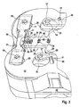
- the cells 12 are in a correspondingly profiled, about hood-shaped in plastic injection molded housing 13 (see. Fig.2 ), from which they protrude with their two cylindrical pole terminals 14.
- free end faces 15 of the two pole terminals 14 of each cell 12 are provided with internally threaded blind holes 16.
- the polarity berschreibende interconnection of the cells 12 by means of massive strip-shaped high-current cell connector 17, each with a through hole 18 on a blind hole 16 are positioned.
- the cell connector 17 by means of the through holes 18 by cross and engaging in the blind holes 16 threaded bolt 19 of screws 20 are fixedly connected to associated pole terminals 14.
- the individual cell connector 17 in a handling technically simple and error-free mounting operation reliable on electrical conductors to corresponding components 22 and circuits 23 are connected.
- the actual, electrically effective strip conductor course then results in a manner known per se, when the stabilization bridges are punched out through openings which are cleared in the envelope 26.
- This board 24 is flat positioned and fixed lying on the housing 13 by means of a plurality of mutually spaced latching hooks 27, which are preferably molded onto the housing 13 and the board 24, pass through it for free-clearance positioning holes 28 or along its outer edge.
- the circuit board 24 is designed with boundaries (or perforations) 29 running in such a way that it does not touch the lateral surfaces of the pole terminals 14, ie it maintains a radially clear distance from them.
- the cell connector 17, which is placed on the pole terminal end faces, is pre-positioned by its longitudinal edges 30 overlapping latchings 31, which, like the latching hooks 27, are molded onto the housing 13, but pass through the board 24 with radial play.
- the contour of the cell connector 17 is formed with at least one lateral projection, which is preferably bent, which is bent to a trunk 32, with its end remote from the actual cell connector 17 end 33 finally, out of the plane of the cell connector 17, in the direction transverse to the plane Cell connector and on the board 24 to points.
- a lateral projection which is preferably bent, which is bent to a trunk 32, with its end remote from the actual cell connector 17 end 33 finally, out of the plane of the cell connector 17, in the direction transverse to the plane Cell connector and on the board 24 to points.
- a mandrel is formed on the underside of the cell connector 17, which - analogous to the trunk 32 - engages in the stamped grid 25.
- a required for the connection of an external circuit 23 data interface is advantageously also integrated into the leadframe 25 by serving particularly narrow grating ends, then serving as plug pins 37, in the course of extrusion coating of the lead frame 25 by a molded connector basket 38 are surrounded.
- the plug pins 37 are bent as outlined in the sense out of the plane of the board 24 out that a plug connection in the course of Aufrastens the board 24 can be completed on the housing 13. Contrary to the schematic representation of Fig.1 This results in a particularly compact construction when the plug basket 38 in one of the axially parallel housing gusset 43 (see. Fig.2 ) is transferred between adjacent cells 12.
- a circuit board 24 in the form of a plastic-encased stamped grid 25 is snapped onto the housing 12 mechanically grouping the cells 12 whose enclosure 26 is in the neighborhood of
- cell connector 17 does not apply higher than the end faces 15 of the cell pole terminals 14 protruding from it at a clear distance from the sheath 26.
Landscapes
- Chemical & Material Sciences (AREA)
- Chemical Kinetics & Catalysis (AREA)
- Electrochemistry (AREA)
- General Chemical & Material Sciences (AREA)
- Connection Of Batteries Or Terminals (AREA)
- Battery Mounting, Suspending (AREA)
- Secondary Cells (AREA)
- Details Of Connecting Devices For Male And Female Coupling (AREA)
Description
- Die Erfindung betrifft eine Anordnung gemäß dem Oberbegriff des Hauptanspruches.
- Eine derartige Anschluss-Anordnung ist aus der
DE 1 98 10 746 B4 bei Akkumulatoren für die elektromotorische Traktion bekannt. Diese Anordnung besteht dort aus einer Schaltungsplatine, deren Leiterbahnen bei Platinenbohrungen kontaktgebend auf die in einer Ebene endenden Polanschlüsse einer Mehrzahl von Zellen gelegt werden, ehe ebenfalls durchbohrte Hochstrom-Zellenverbinder darüber gesetzt werden, mittels derer die Zellen dann zum Zellenpack des Akkumulators zusammengeschaltet sind. Diese zweilagige Anordnung aus Zellenverbinder und darunter eingespannter Schaltungsplatine wird mittels Schrauben fixiert, welche deren Löcher durchgreifend in Innengewinde der Polanschlüsse eingeschraubt werden. Die auf der Schaltungsplatine ausgebildeten Leiterbahnen führen von den längs des Randes der Platine gelegenen Polanschlüssen zum mittleren Bereich der Platine, der mit einer Schaltung für ein Batteriemanagement bestückt ist, und zu Shunts für einen Abgleich der Ladezustände der einzelnen Zellen untereinander sowie zu Vielfachsteckern als Datenschnittstellen. Weil die Platine dadurch einerseits jeweils zwischen den massiven Zellenverbindern und den Polanschlüssen bei vielfach überbestimmter Lagerung starr verschraubt ist, während andererseits betriebsbedingt Erschütterungen und temperaturabhängige Kräfte von den Polanschlüssen über die Platine auf die Zellenverbinder einwirken, wird für die Platine ein flexibles Material gewählt. Das beschwört aber die Gefahr von Brüchen der Leiterbahnen gerade in unmittelbarer Nachbarschaft der Polverschraubungen und somit des Ausfalles des gesamten Zellenpacks eines solchen Traktions-Akkumulators wegen nicht mehr funktionstüchtigen Batteriemanagements herauf. - Weitere Zellverbindungssysteme zur Verbindung von Zellen von Akkumulatoren sind beispielsweise aus den Dokumenten
GB 2 330 252 A US 2006/0292419 A1 ,WO 2007/033689 A1 undDE 101 34 143 A1 bekannt, die allesamt jeweils spezielle Lösungen zur leistungs- und/oder signalseitigen Verschaltung von Batteriezellen darstellen. - In Erkenntnis dieser Gegebenheiten liegt vorliegender Erfindung die technische Problemstellung zugrunde, eine bei einfach zu handhabender Polanschlusstechnologie betriebsunabhängig zuverlässige Anschlussanordnung insbesondere für das Batteriemanagement anzugeben.
- Diese Aufgabe ist nach vorliegender Erfindung gemäß den Merkmalen des Hauptanspruches gelöst. Danach ist die Platine von den Polanschlüssen und damit von den Zellen mechanisch entkoppelt, indem die Platine nicht mehr an den Polanschlüssen, sondern auf einem Teil eines die Zellen aufnehmenden Akkumulator-Gehäuses mechanisch festgelegt ist. Dann greift ein zunächst nur auf den Polanschlüssen positionierter und später, dann ohne Einspannen der Platine, mit jenen zu verschraubender Zellenverbinder vorzugsweise mit einem aus seiner Ebene abgewinkelt verlaufenden hier so genannten Rüssel (oder alternativ mit einem senkrecht zu seiner Ebene an ihm angeformten Dorn) nachgiebig in eine umspritzte Stanzgitterstruktur der auf dem Akkumulator-Gehäuse festgelegten Platine kontaktgebend ein.
- Dazu ragen in eine Aussparung in der Kunststoff-Umhüllung wenigstens zwei am Stanzgitter freigeschnittene Laschen stirnseitig aufeinander zu weisend geringfügig federnd hinein. Beim Aufdrücken des Zellenverbinders auf die Polanschlüsse senkt sich der aus der Ebene des Zellenverbinders abgewinkelte Rüssel in die Aussparung und darin zwischen die Stirnränder der Laschen, die dadurch geringfügig in Eintauchrichtung ausbiegen und so den Rüssel, kraftschlüssig gegen Zurückgleiten gesichert, festklemmen. Dadurch ist der Zellenverbinder zur abschließenden Verschraubung auf seinen Polanschlüssen vormontiert und zugleich bereits an die elektrische Leiterbahnenstruktur des Stanzgitters angeschlossen.
- Zweckmäßigerweise sind weitere am Stanzgitter freigeschnittene Laschen, mit ihren Stirnenden durch Öffnungen in der Umhüllung hervorragend, aus der Ebene des Stanzgitters herausgebogen, so dass an sie, und damit an die Leiterbahnenstruktur der Platine in Form des umspritzten Stanzgitters, Bauelemente wie Messwiderstände für das Batteriemanagement und insbesondere Ladungsausgleich-Widerstände angeschlossen werden können. Die für letztere im Vergleich zu bloßen Messdatenpfaden großen erforderlichen Leiterquerschnitte lassen sich ohne weiteres, und problemloser als bei aufkaschierten Leiterbahnen, durch entsprechend angepasste Breiten der Stanzgitterbahnen übereinstimmender Dicke zur Verfügung stellen. Wenn in die Stirnenden solcher Anschlusslaschen etwa v-förmig sich öffnende, sehr spitzwinklige Einschnitte eingestanzt sind, dann lassen sich die Anschlüsse der Widerstände und sonstiger Bauelemente hier, zu lotfreier Bestückung in Richtung des Eingriffes des Rüssels in das Stanzgitter und somit gegen das die Platine abstützende Akkumulator-Gehäuse, handhabungstechnisch einfach unmittelbar einklemmen.
- Andere Stirnenden von Stanzgitter-Laschen können filigran schmal endend gestanzt sein, um, vor dem Ausbilden eines Steckerkorbes im Zuge des Umspritzens des Stanzgitters mit seiner Kunststoff-Umhüllung, unmittelbar zu Steckerstiften etwa aus der Ebene des Stanzgitters herausgebogen zu werden. Dadurch brauchen nicht mehr individuelle Stecker für Datenschnittstellen gesondert auf die Platine montiert zu werden. Im Rahmen vorliegender Erfindung muss die Platine nicht unter den Polverbindern angeordnet sein; die Rüssel können durchaus auch zum Eingriff in eine darüber gelegene Platine von ihrem jeweiligen Polverbinder hochragen. Zweckmäßiger ist aber die großflächige Auflage der rückwärtig flachen Stanzgitter-Platine auf dem Akkumulator-Gehäuse unter jeweils radialem Abstand zu den Polanschlüssen, auf die dann die mit ihren Rüsseln lokal in das Stanzgitter der Platine eingreifenden Zellenverbinder aufgeschraubt werden, ohne die Stanzgitter-Umhüllung dabei mechanisch einzuspannen.
- Zusätzliche Alternativen und Weiterbildungen der erfindungsgemäßen Lösung ergeben sich aus den weiteren Ansprüchen und, auch unter Berücksichtigung deren Vorteilen, aus nachstehender Beschreibung eines unter Beschränkung auf das Funktionswesentliche nicht ganz maßstabsgerecht vergrößert skizzierten bevorzugten Realisierungsbeispieles zur Erfindung. In der Zeichnung ist eine erfindungsgemäße Anschluss-Anordnung mit dem Eingriff eines Zellenverbinders über seinen Rüssel in das umspritzte Stanzgitter der Platine
- in Fig.1
- in abgebrochener Querschnittsdarstellung und
- in Fig.2
- in abgebrochener Schrägansicht gegen ein platinenseitig bestücktes Gehäuse, ohne die Zellen, veranschaulicht.
- Ein etwa Traktionszwecken dienender Akkumulator 11 stellt eine Zusammenschaltung mehrerer Zellen 12 in gegenseitiger Serien- und/oder Parallelschaltung dar. Dafür sind die Zellen 12 in einem entsprechend profilierten, etwa haubenförmig im KunststoffSpritzguss gefertigten Gehäuse 13 (vgl.
Fig.2 ) gehaltert, aus dem sie mit ihren beiden zylindrischen Polanschlüssen 14 hervorragen. In die in einer Ebene liegenden freien Stirnflächen 15 der beiden Polanschlüsse 14 einer jeden Zelle 12 öffnen sich mit Innengewinden versehene Sacklöcher 16. Das polaritätsberücksichtigende Zusammenschalten der Zellen 12 erfolgt mittels massiver streifenförmiger Hochstrom-Zellenverbinder 17, die dafür jeweils mit einem Durchgangsloch 18 über einem Sackloch 16 positioniert sind. So kann der Zellenverbinder 17 mittels dessen Durchgangslöcher 18 durchgreifender und in die Sacklöcher 16 eingreifender Gewindebolzen 19 von Schrauben 20 fest mit zugeordneten Polanschlüssen 14 verbunden werden. - Für ein Batteriemanagement 21, das im Interesse der Lebensdauer und Leistungsfähigkeit der Zellen 12 deren Lade- und Entladezyklen steuert und einen Ladungsausgleich der Zellen 12 untereinander regelt, sollen die einzelnen Zellenverbinder 17 in einem handhabungstechnisch möglichst einfachen und irrtumsfreien Montagevorgang betriebszuverlässig über elektrische Leiter an entsprechende Bauelemente 22 und Schaltungen 23 angeschlossen werden. Das wird mittels einer Platine 24 bewerkstelligt, die aus einem Stanzgitter 25 besteht, welches, vor dem endgültigen Auftrennen von der Handhabung dienenden Stabilisierungsbrücken, im Kunststoffspritzguss eine im Wesentlichen flache aber relativ steife und mechanisch hoch belastbare Umhüllung 26 erfährt. Der eigentliche, elektrisch wirksame Leiterbahnenverlauf ergibt sich dann in als solcher bekannter Weise, wenn durch in der Umhüllung 26 freigesparte Öffnungen hindurch die Stabilisierungsbrücken herausgestanzt werden.
- Diese Platine 24 wird flach auf dem Gehäuse 13 aufliegend mittels mehrerer zueinander distanziert angeordneter Rasthaken 27 positioniert und fixiert, die vorzugsweise an das Gehäuse 13 angespritzt sind und die Platine 24, durch dafür freigesparte Positionierlöcher 28 hindurch oder längs ihres Außenrandes, übergreifen. Im Übrigen ist die Platine 24 mit derart verlaufenden Berandungen (oder Durchbrechungen) 29 ausgelegt, dass sie die Mantelflächen der Polanschlüsse 14 nicht berührt, also radial lichten Abstand zu jenen einhält.
- Jedenfalls im Bereiche des Verlaufes von Zellenverbindern 17 trägt die auf dem Gehäuse 13 aufliegende Platine 24 geringfügig weniger stark, jedenfalls nicht stärker auf, als die lichte Höhe der Polanschlüsse 14. Wenn ein Zellenverbinder 17 auf deren Stirnflächen 15 aufgelegt und mittels der Schrauben 20 gegen diese verspannt wird, erfolgt dadurch deshalb kein sandwichartiges Einklemmen der darunter auf das Gehäuse 13 montierten Platine 24. Die ist und bleibt relativ weich und deshalb mechanisch schonend über die Rasthaken 27 an ihre großflächige Auflage in Form des Gehäuses 13 angeschlossen.
- Der auf die Polanschluss-Stirnflächen aufgelegte Zellenverbinder 17 wird vor seinem Verschrauben durch seine Längsränder 30 übergreifende Verrastungen 31 vorpositioniert, die wie die Rasthaken 27 an das Gehäuse 13 angeformt sind aber die Platine 24 unter radialem Spiel durchgreifen.
- Die Kontur des Zellenverbinders 17 ist mit wenigstens einer seitlichen Ausladung ausgebildet, vorzugsweise gestanzt, die zu einem Rüssel 32 gebogen wird, der mit seinem vom eigentlichen Zellenverbinder 17 abgelegenen Ende 33 schließlich, aus der Ebene des Zellverbinders 17 heraus, in Richtung quer zur Ebene des Zellenverbinders und auf die Platine 24 zu weist. Beim Eindrücken in die Verrastungen 31 taucht dieses Ende 33 deshalb in die Ebene des Stanzgitters 25 hinein, nämlich in eine Aussparung 34 in dessen Umhüllung 26. In diese Aussparung 34 kragen wenigstens zwei am Stanzgitter 25 freigestanzte Klemmlaschen 35 distanziert aufeinander zu weisend vor. Die werden vom Ende 33 des Rüssels 32 wie skizziert in Einsteckrichtung geringfügig elastisch voneinander fort gebogen und verkanten sich dadurch an den Mantelflächen 36 des Rüssels 32.
- Der im Zuge der Vormontage des Zellenverbinders 17 in das Stanzgitter 25 eingreifende Rüssel 32 stellt so einen wünschenswert elastisch nachgiebigen aber zugleich hoch erschütterungsfesten sowohl mechanischen wie auch elektrischen Anschluss des auf einander benachbarten Polanschlüssen 14 verschraubten Zellenverbinders 17 an die Verdrahtung in Form des Stanzgitters 25 dar.
- Alternativ ist an der Unterseite des Zellenverbinders 17 ein Dorn angeformt, der - analog dem Rüssel 32 - in das Stanzgitter 25 eingreift.
- Eine für den Anschluss einer externen Schaltung 23 erforderliche Datenschnittstelle wird zweckmäßigerweise ebenfalls in das Stanzgitter 25 integriert, indem besonders schmal ausgelegte Gitter-Enden, dann als Steckerstifte 37 dienend, im Zuge des Umspritzens des Stanzgitters 25 von einem angespritzten Steckerkorb 38 umgeben werden. Zweckmäßigerweise werden die Steckerstifte 37 wie skizziert in dem Sinne aus der Ebene der Platine 24 heraus gebogen, dass hier eine Steckverbindung im Zuge des Aufrastens der Platine 24 auf das Gehäuse 13 vollzogen werden kann. Entgegen der Prinzipdarstellung der
Fig.1 ergibt sich ein besonders gedrängter Aufbau, wenn der Steckerkorb 38 in einen der achsparallelen Gehäuse-Zwickel 43 (vgl.Fig.2 ) zwischen einander benachbarten Zellen 12 verlegt wird. - Strombedingt größere Leiterquerschnitte für den Anschluss etwa von Widerständen 39 zum Zellenladungsausgleich werden zweckmäßigerweise innerhalb des Stanzgitters 25 durch entsprechend verbreiterte Bahnen realisiert. Eine besonders vorteilhafte Bestückungsmöglichkeit ergibt sich dadurch, dass in Platinen-Aussparungen 34 abseits der Zellenverbinder 17 freigestanzte und dabei stirnseitig mit schmalen V-Einschnitten 42 (vgl.
Fig.2 ) ausgestattete Bahnenenden zu Bestückungsklemmen 40 aus der Ebene der Platine 24 entgegen der Eintauchrichtung des Rüssels 32 herausgebogen werden. In die brauchen dann die Anschlüsse 41 der Bauelemente nur noch in Richtung der Platinenmontage, also gegen die stabilisierende Unterlage des Gehäuses 13 eingedrückt und dadurch zu lötfreier Bestückung verklemmt zu werden. - So erfolgen alle, mechanischen wie elektrischen, Montagevorgänge in derselben Orientierung: Zunächst die Verrastung der Stanzgitter-Platine 24 auf dem Akkumulator-Gehäuse 13 samt Steckvorgang im Korb 38, dann das Eindrücken des Zellenverbinder-Rüssels 32 in das und das Aufdrücken der Bauelementen-Anschlüsse 41 auf das Stanzgitter 25.
- Um die auch sehr starke Ströme führenden Zellenverbinder 17 etwa eines Traktions-Akkumulators 11 fehlerresistent und funktionssicher etwa an ein Batteriemanagement 21 anschließen zu können, wird also erfindungsgemäß auf das die Zellen 12 mechanisch gruppierende Gehäuse 13 zunächst eine Platine 24 in Form eines kunststoffumspritzten Stanzgitters 25 aufgerastet, deren Umhüllung 26 in der Nachbarschaft der Zellenverbinder 17 jedenfalls nicht höher als die Stirnflächen 15 der unter lichtem Abstand zur Umhüllung 26 daraus hervorragenden Zellen-Polanschlüsse 14 aufträgt. Bei der Vormontage eines Zellenverbinders 17 auf Polanschlüssen 14 taucht dieser mit einem von ihm abgebogen verlaufenden Rüssel 32 in die Ebene des Stanzgitters 25 ein und verkantet sich dabei zwischen wenigstens zwei aufeinander zu weisenden Klemmlaschen 35, womit unter einer einzigen Montagerichtung der zuverlässige mechanische und elektrische Anschluss der Zellenverbinders 17 an das Stanzgitter 25 der Verdrahtungs-Platine 24 hergestellt ist.
-
- 11
- Akkumulator (aus 12-12)
- 12
- Zelle (in 13 gehaltert)
- 13
- Gehäuse (von 11)
- 14
- Polanschluss (von 12)
- 15
- Stirnfläche (von 14)
- 16
- Sackloch (in 14)
- 17
- Zellenverbinder (über 14-14)
- 18
- Durchgangsloch (in 17 über 16)
- 19
- Gewindebolzen (in 16)
- 20
- Schraube (mit 19)
- 21
- Batteriemanagement (für 12-12)
- 22
- Bauelement (in 23)
- 23
- (externe) Schaltung (an 38)
- 24
- Platine (aus 25-26)
- 25
- Stanzgitter (in 26)
- 26
- Umhüllung (von 25)
- 27
- Rasthaken (an 13 für 24)
- 28
- Positionierloch (an 24 für 27)
- 29
- Berandung/Durchbrechung (an/in 24, gegenüber 14 distanziert)
- 30
- Längsrand (von 17)
- 31
- Verrastung (zwischen 13 und 17)
- 32
- Rüssel (an 17, zwischen 35-35)
- 33
- Ende (von 32)
- 34
- Aussparung (in 24)
- 35
- Klemmlaschen (gegen 32)
- 36
- Mantelfläche (von 32)
- 37
- Steckerstift (in 38)
- 38
- Steckerkorb (um 37)
- 39
- Widerstand (auf 40)
- 40
- Bestückungsklemme (für 39)
- 41
- Anschluss (von 39)
- 42
- Einschnitt (in 40 für 41)
- 43
- Zwickel (außen an 13, für 38)
Claims (13)
- Anordnung zum Anschließen von elektrischen Leiterbahnen einer Platine (24) an Polanschlüsse (14) von mittels Zellenverbindern (17) zusammengeschalteten Zellen (12) eines Akkumulators, wobei eine unter lichtem Abstand zu den Polanschlüssen (14) gehalterte Platine (24) eine Leiterbahnstruktur in Form eines von einer Umhüllung (26) umspritzten Stanzgitters (25) aufweist, wobei in Form eines Dorns ausgebildete oder zu einem Rüssel (32) gebogene, seitliche Ausladungen der Zellenverbinder (17) in jeweilige Aussparungen (34) in der Umhüllung eingreifen derart, dass ein elastisch nachgiebiger und zugleich hoch erschütterungsfester sowohl mechanischer wie auch elektrischer Anschluss des Zellenverbinders (17) an die Leiterbahnstruktur des Stanzgitters (25) hergestellt wird.
- Anordnung nach dem vorangehenden Anspruch, dadurch gekennzeichnet, dass der vom Zellenverbinder (17) abstehende Rüssel (32) sich in eine Richtung quer zur Ebene des Zellverbinders (17) erstreckt.
- Anordnung nach einem der vorangehenden Ansprüche, dadurch gekennzeichnet, dass der Eingriff zwischen, in einer Aussparung (34) der Umhüllung (26) des Stanzgitters (25) aufeinander zu weisende, Klemmlaschen (35) erfolgt.
- Anordnung nach einem der vorangehenden Ansprüche, dadurch gekennzeichnet, dass die Umhüllung (26) in der Umgebung von Zellenverbindern (17) nicht höher als die Polanschlüsse (14) aufträgt.
- Anordnung nach einem der vorangehenden Ansprüche, dadurch gekennzeichnet, dass die Umhüllung (26) auf einem Gehäuse (13) für eine Gruppierung der Zellen (12) verrastet ist.
- Anordnung nach dem vorangehenden Anspruch, dadurch gekennzeichnet, dass vom Gehäuse (13) entgegen der Einsteckrichtung des Rüssels (32) vorragende Rasthaken (27) die Umhüllung (26) an Positionierlöchern (28) durchgreifen.
- Anordnung nach einem der beiden vorangehenden Ansprüche, dadurch gekennzeichnet, dass auch die Zellenverbinder (17) an dem Gehäuse.(13) verrastet sind.
- Anordnung nach dem vorangehenden Anspruch, dadurch gekennzeichnet, dass die Zellenverbinder (17) mit den Zellen (12) über in Sacklöcher (16) in deren Polanschlüssen (14) eingreifende Schrauben (20) ohne axiale Beanspruchung der Stanzgitter-Umhüllung (26) verbunden sind.
- Anordnung nach einem der vorangehenden Ansprüche, dadurch gekennzeichnet, dass an die Umhüllung (26) ein Steckerkorb (38) angeformt ist, in dem am Stanzgitter (25) freigestanzte Steckerstifte (37) enden.
- Anordnung nach dem vorangehenden Anspruch, dadurch gekennzeichnet, dass die Steckerstifte (37) in gleicher Steckrichtung wie die Rüssel (32) orientiert sind.
- Anordnung nach einem der vorangehenden Ansprüche, dadurch gekennzeichnet, dass aus der Ebene des Stanzgitters (25), aus diesem freigestanzte, Bestückungsklemmen (40) durch Umhüllungs-Aussparungen (34) hindurch abgekantet sind.
- Anordnung nach dem vorangehenden Anspruch, dadurch gekennzeichnet, dass zu lötfreier Montage von Bauelemente-Anschlüssen (41) in den Stirnenden der Bestückungsklemmen (40) V-förmig sich öffnende schmale Kerben freigestanzt sind.
- Anordnung nach einem der vorangehenden Ansprüche, dadurch gekennzeichnet, dass die Montage der Stanzgitter-Umhüllung (26) auf dem Gehäuse (13) in gleicher Richtung wie die Steckrichtung eines Steckerkorbes (38) und die Montagerichtung des Zellenverbinders (17) samt Eindrückrichtung seines Rüssels (32) sowie die Bestückungsrichtung etwa von Widerständen (39) auf der Platine (24) orientiert ist.
Applications Claiming Priority (3)
| Application Number | Priority Date | Filing Date | Title |
|---|---|---|---|
| DE102009034786 | 2009-07-25 | ||
| DE102009041738.9A DE102009041738B4 (de) | 2009-07-25 | 2009-09-16 | Anordnung zum Anschließen von elektrischen Leiterbahnen an Polanschlüsse von zusammengeschalteten Zellen |
| PCT/EP2010/004139 WO2011012215A1 (de) | 2009-07-25 | 2010-07-07 | Anordnung zum anschliessen von elektrischen leiterbahnen an polanschlüsse von zusammengeschalteten zellen |
Publications (2)
| Publication Number | Publication Date |
|---|---|
| EP2460212A1 EP2460212A1 (de) | 2012-06-06 |
| EP2460212B1 true EP2460212B1 (de) | 2013-09-25 |
Family
ID=43402740
Family Applications (1)
| Application Number | Title | Priority Date | Filing Date |
|---|---|---|---|
| EP10740151.5A Not-in-force EP2460212B1 (de) | 2009-07-25 | 2010-07-07 | Anordnung zum anschliessen von elektrischen leiterbahnen an polanschlüsse von zusammengeschalteten zellen |
Country Status (11)
| Country | Link |
|---|---|
| US (1) | US8976534B2 (de) |
| EP (1) | EP2460212B1 (de) |
| JP (1) | JP2013500555A (de) |
| CN (1) | CN102484236B (de) |
| BR (1) | BR112012001695A2 (de) |
| CA (1) | CA2769284A1 (de) |
| DE (1) | DE102009041738B4 (de) |
| IN (1) | IN2012DN00253A (de) |
| MX (1) | MX2012000873A (de) |
| RU (1) | RU2547454C2 (de) |
| WO (1) | WO2011012215A1 (de) |
Families Citing this family (18)
| Publication number | Priority date | Publication date | Assignee | Title |
|---|---|---|---|---|
| JP5418522B2 (ja) * | 2011-03-07 | 2014-02-19 | 株式会社オートネットワーク技術研究所 | 電池接続アセンブリ及び電池モジュール |
| DE102011087035A1 (de) * | 2011-11-24 | 2013-05-29 | Bayerische Motoren Werke Aktiengesellschaft | Zellkontaktieranordnung für einen Energiespeicher |
| DE102011087032A1 (de) | 2011-11-24 | 2013-05-29 | Bayerische Motoren Werke Aktiengesellschaft | Hochvoltspeicher |
| KR20140010633A (ko) * | 2012-07-16 | 2014-01-27 | 삼성에스디아이 주식회사 | 배터리 팩 |
| FR2996363B1 (fr) * | 2012-10-02 | 2016-10-07 | Renault Sa | Dispositif pour le montage rapide de connexions electriques, notamment sur une batterie de traction |
| EP2744014B1 (de) * | 2012-12-12 | 2015-07-29 | MAGNA STEYR Battery Systems GmbH & Co OG | Batteriesystem und Verfahren zur Herstellung eines Batteriesystems |
| US9318729B2 (en) * | 2013-04-05 | 2016-04-19 | Makita Corporation | Power tool battery pack |
| DE102013016845A1 (de) | 2013-10-10 | 2015-04-16 | Daimler Ag | Batteriemanagementmodul und Verfahren zu dessen Herstellung |
| DE102016103667A1 (de) * | 2016-03-01 | 2017-09-07 | Unicorn Energy GmbH | Batteriepack und Verfahren zur Herstellung eines Batteriepacks |
| JP6780288B2 (ja) * | 2016-05-09 | 2020-11-04 | 株式会社オートネットワーク技術研究所 | 接続モジュール |
| US11507714B2 (en) * | 2020-01-28 | 2022-11-22 | Middle Chart, LLC | Methods and apparatus for secure persistent location based digital content |
| DE102017207055A1 (de) * | 2017-04-26 | 2018-10-31 | Volkswagen Aktiengesellschaft | Elektrochemischer Energiespeicher, Zellcontroller, Energiespeichersystem, Fortbewegungsmittel und Kontaktierungseinrichtung für ein elektrisches Energiespeichersystem |
| US20190363326A1 (en) * | 2018-05-22 | 2019-11-28 | GM Global Technology Operations LLC | Battery assembly with multi-piece bus bar cap assembly |
| JP7028105B2 (ja) * | 2018-08-29 | 2022-03-02 | 住友電装株式会社 | 電池配線モジュール |
| CN114270631B (zh) * | 2019-09-11 | 2024-01-23 | 西门子股份公司 | 电路板连接结构 |
| US11695182B2 (en) | 2019-09-30 | 2023-07-04 | Makita Corporation | Battery pack |
| CN212323124U (zh) * | 2020-05-27 | 2021-01-08 | 东莞新能安科技有限公司 | 一种电池包及电动设备 |
| DE102023110783A1 (de) * | 2023-04-26 | 2024-10-31 | Yazaki Systems Technologies Gmbh | Verbindungssystem für einen elektrischen Energiespeicher eines Fahrzeugs, elektrischer Energiespeicher und Verfahren zur Herstellung des Verbindungssystems |
Family Cites Families (15)
| Publication number | Priority date | Publication date | Assignee | Title |
|---|---|---|---|---|
| DE4430798A1 (de) * | 1994-08-30 | 1996-03-07 | Siemens Ag | Stanzgitter zur Verbindung von elektrischen Bauelementen |
| SU1429348A2 (ru) * | 1986-08-08 | 1988-10-07 | Предприятие П/Я В-2655 | Контактное устройство |
| DE3643288A1 (de) * | 1986-12-18 | 1988-06-30 | Semikron Elektronik Gmbh | Halbleiterbaueinheit |
| US5185734A (en) | 1990-07-20 | 1993-02-09 | International Business Machines Corporation | Calibrating and power-protecting laser drive circuits |
| JP3343889B2 (ja) | 1997-10-13 | 2002-11-11 | トヨタ自動車株式会社 | バッテリーホルダ用接続プレート |
| DE19810746B4 (de) | 1998-03-12 | 2008-10-16 | Varta Automotive Systems Gmbh | Platine mit einer Schaltung zur Überwachung einer mehrzelligen Akkumulatorenbatterie |
| RU2160195C2 (ru) * | 1999-02-17 | 2000-12-10 | Открытое акционерное общество "Тверской вагоностроительный завод" | Модуль аккумуляторный подвагонный (варианты) |
| RU2145754C1 (ru) * | 1999-05-11 | 2000-02-20 | Закрытое акционерное общество "Проимпэкс КомТех" | Соединительный модуль (варианты) |
| DE10134143A1 (de) * | 2001-07-13 | 2003-01-30 | Daimler Chrysler Ag | System zur Verschaltung von Schwachstromkomponenten mit Zellen in Hochleitstungsstromquellen |
| JP4036805B2 (ja) * | 2003-08-05 | 2008-01-23 | 三洋電機株式会社 | パック電池 |
| US20060292419A1 (en) | 2005-06-23 | 2006-12-28 | Ko-Chen Shen | Secondary cell device having connection interface |
| US8663834B2 (en) | 2005-09-20 | 2014-03-04 | Metabowerke Gmbh | Rechargeable battery pack and electrical hand tool device |
| KR101260470B1 (ko) * | 2006-04-07 | 2013-05-06 | 타이코에이엠피(유) | 배터리 셀 모듈의 접속장치 |
| JP2009087542A (ja) | 2007-09-27 | 2009-04-23 | Toshiba Corp | 組電池および組電池用バスバー |
| EP2048725A1 (de) * | 2007-10-12 | 2009-04-15 | Valeo Equipements Electriques Moteur | Vorrichtung zum Speichern von elektrischer Energie, insbesondere zur Ausstattung eines Kraftfahrzeugs |
-
2009
- 2009-09-16 DE DE102009041738.9A patent/DE102009041738B4/de not_active Expired - Fee Related
-
2010
- 2010-07-07 IN IN253DEN2012 patent/IN2012DN00253A/en unknown
- 2010-07-07 JP JP2012521994A patent/JP2013500555A/ja active Pending
- 2010-07-07 US US13/386,733 patent/US8976534B2/en not_active Expired - Fee Related
- 2010-07-07 WO PCT/EP2010/004139 patent/WO2011012215A1/de not_active Ceased
- 2010-07-07 EP EP10740151.5A patent/EP2460212B1/de not_active Not-in-force
- 2010-07-07 BR BR112012001695-4A patent/BR112012001695A2/pt not_active IP Right Cessation
- 2010-07-07 MX MX2012000873A patent/MX2012000873A/es not_active Application Discontinuation
- 2010-07-07 CA CA2769284A patent/CA2769284A1/en not_active Abandoned
- 2010-07-07 RU RU2012106260/07A patent/RU2547454C2/ru not_active IP Right Cessation
- 2010-07-07 CN CN201080032567.7A patent/CN102484236B/zh not_active Expired - Fee Related
Also Published As
| Publication number | Publication date |
|---|---|
| CN102484236A (zh) | 2012-05-30 |
| IN2012DN00253A (de) | 2015-05-01 |
| CN102484236B (zh) | 2015-03-25 |
| DE102009041738A1 (de) | 2011-02-03 |
| EP2460212A1 (de) | 2012-06-06 |
| JP2013500555A (ja) | 2013-01-07 |
| BR112012001695A2 (pt) | 2018-04-10 |
| RU2012106260A (ru) | 2013-09-10 |
| DE102009041738B4 (de) | 2015-11-05 |
| MX2012000873A (es) | 2012-03-26 |
| RU2547454C2 (ru) | 2015-04-10 |
| CA2769284A1 (en) | 2011-02-03 |
| US20120127676A1 (en) | 2012-05-24 |
| WO2011012215A1 (de) | 2011-02-03 |
| US8976534B2 (en) | 2015-03-10 |
Similar Documents
| Publication | Publication Date | Title |
|---|---|---|
| DE102009041738B4 (de) | Anordnung zum Anschließen von elektrischen Leiterbahnen an Polanschlüsse von zusammengeschalteten Zellen | |
| EP2989676B2 (de) | Zellkontaktierungssystem für eine elektrochemische vorrichtung | |
| DE69734095T2 (de) | Energieverteilungseinheit | |
| EP2989669A1 (de) | Verfahren zum herstellen eines batterienkontaktierungssystems und batterienkontaktierungssystem | |
| DE102017214303A1 (de) | Anordnung zur elektrischen Kontaktierung von Zellmodulen einer Batterie, Batterie mit einer derartigen Anordnung sowie Fahrzeug | |
| DE102020123476A1 (de) | Ladedose mit Schnittstelle | |
| DE102010017361A1 (de) | Anbausteckverbinder | |
| DE102015110308B4 (de) | Akkupack für ein Elektrohandwerkzeuggerät | |
| DE102013213848A1 (de) | Abdeckung für Batterien | |
| EP2085785B1 (de) | Vorrichtung zur Strommessung | |
| DE3922072C2 (de) | ||
| DE10338279B4 (de) | Steckverbindervorrichtung | |
| DE102013217836B4 (de) | Traktionsbatterie für ein Fahrzeug sowie Verfahren zur Herstellung dafür | |
| DE102019213450B3 (de) | Batteriemodul und elektrisch angetriebenes Kraftfahrzeug | |
| DE112015004880B4 (de) | Elektrischer Verteilerkasten | |
| EP0895660B1 (de) | Kabelsteckverbinder mit in einem isolationskörper befestigten kontaktbahnen mit lötanschlüssen | |
| DE102021134339B3 (de) | Kraftfahrzeugbatterie mit verbesserter elektrischer Anbindung einer zugehörigen elektronischen Steuer- und/oder Überwachungsschaltung sowie zugehöriges Montageverfahren | |
| DE102009053015A1 (de) | Anschlussmodul für Solarpanele mit vorgefertigtem Anschluss-Strang | |
| DE102009054770A1 (de) | Steuergerät für ein Kraftfahrzeug und zugehöriges Verfahren zur Montage eines Steuergeräts für ein Kraftfahrzeug | |
| DE102019216717A1 (de) | Batteriemodul | |
| DE102013015756A1 (de) | Zellblock für eine Batterie | |
| DE102024136148B3 (de) | Batteriepack mit lösbarem Elektronikmodul | |
| DE102015004464B4 (de) | Energiespeicheranordnung, insbesondere für ein Kraftfahrzeug | |
| WO1997049147A1 (de) | Federleiste für steckverbindungen zwischen einer baugruppenleiterplatte und einer rückwandverdrahtungsplatte | |
| DE102024002594A1 (de) | Zellüberwachungsvorrichtung und Batterie |
Legal Events
| Date | Code | Title | Description |
|---|---|---|---|
| PUAI | Public reference made under article 153(3) epc to a published international application that has entered the european phase |
Free format text: ORIGINAL CODE: 0009012 |
|
| 17P | Request for examination filed |
Effective date: 20111213 |
|
| AK | Designated contracting states |
Kind code of ref document: A1 Designated state(s): AL AT BE BG CH CY CZ DE DK EE ES FI FR GB GR HR HU IE IS IT LI LT LU LV MC MK MT NL NO PL PT RO SE SI SK SM TR |
|
| DAX | Request for extension of the european patent (deleted) | ||
| GRAP | Despatch of communication of intention to grant a patent |
Free format text: ORIGINAL CODE: EPIDOSNIGR1 |
|
| INTG | Intention to grant announced |
Effective date: 20130524 |
|
| GRAS | Grant fee paid |
Free format text: ORIGINAL CODE: EPIDOSNIGR3 |
|
| GRAA | (expected) grant |
Free format text: ORIGINAL CODE: 0009210 |
|
| AK | Designated contracting states |
Kind code of ref document: B1 Designated state(s): AL AT BE BG CH CY CZ DE DK EE ES FI FR GB GR HR HU IE IS IT LI LT LU LV MC MK MT NL NO PL PT RO SE SI SK SM TR |
|
| REG | Reference to a national code |
Ref country code: GB Ref legal event code: FG4D Free format text: NOT ENGLISH |
|
| REG | Reference to a national code |
Ref country code: CH Ref legal event code: EP |
|
| REG | Reference to a national code |
Ref country code: AT Ref legal event code: REF Ref document number: 634022 Country of ref document: AT Kind code of ref document: T Effective date: 20131015 |
|
| REG | Reference to a national code |
Ref country code: IE Ref legal event code: FG4D Free format text: LANGUAGE OF EP DOCUMENT: GERMAN |
|
| REG | Reference to a national code |
Ref country code: DE Ref legal event code: R096 Ref document number: 502010004868 Country of ref document: DE Effective date: 20131128 |
|
| PG25 | Lapsed in a contracting state [announced via postgrant information from national office to epo] |
Ref country code: HR Free format text: LAPSE BECAUSE OF FAILURE TO SUBMIT A TRANSLATION OF THE DESCRIPTION OR TO PAY THE FEE WITHIN THE PRESCRIBED TIME-LIMIT Effective date: 20130925 Ref country code: NO Free format text: LAPSE BECAUSE OF FAILURE TO SUBMIT A TRANSLATION OF THE DESCRIPTION OR TO PAY THE FEE WITHIN THE PRESCRIBED TIME-LIMIT Effective date: 20131225 Ref country code: LT Free format text: LAPSE BECAUSE OF FAILURE TO SUBMIT A TRANSLATION OF THE DESCRIPTION OR TO PAY THE FEE WITHIN THE PRESCRIBED TIME-LIMIT Effective date: 20130925 Ref country code: SE Free format text: LAPSE BECAUSE OF FAILURE TO SUBMIT A TRANSLATION OF THE DESCRIPTION OR TO PAY THE FEE WITHIN THE PRESCRIBED TIME-LIMIT Effective date: 20130925 |
|
| REG | Reference to a national code |
Ref country code: NL Ref legal event code: VDEP Effective date: 20130925 |
|
| REG | Reference to a national code |
Ref country code: LT Ref legal event code: MG4D |
|
| PG25 | Lapsed in a contracting state [announced via postgrant information from national office to epo] |
Ref country code: SI Free format text: LAPSE BECAUSE OF FAILURE TO SUBMIT A TRANSLATION OF THE DESCRIPTION OR TO PAY THE FEE WITHIN THE PRESCRIBED TIME-LIMIT Effective date: 20130925 Ref country code: FI Free format text: LAPSE BECAUSE OF FAILURE TO SUBMIT A TRANSLATION OF THE DESCRIPTION OR TO PAY THE FEE WITHIN THE PRESCRIBED TIME-LIMIT Effective date: 20130925 Ref country code: GR Free format text: LAPSE BECAUSE OF FAILURE TO SUBMIT A TRANSLATION OF THE DESCRIPTION OR TO PAY THE FEE WITHIN THE PRESCRIBED TIME-LIMIT Effective date: 20131226 Ref country code: LV Free format text: LAPSE BECAUSE OF FAILURE TO SUBMIT A TRANSLATION OF THE DESCRIPTION OR TO PAY THE FEE WITHIN THE PRESCRIBED TIME-LIMIT Effective date: 20130925 |
|
| PG25 | Lapsed in a contracting state [announced via postgrant information from national office to epo] |
Ref country code: RO Free format text: LAPSE BECAUSE OF FAILURE TO SUBMIT A TRANSLATION OF THE DESCRIPTION OR TO PAY THE FEE WITHIN THE PRESCRIBED TIME-LIMIT Effective date: 20130925 Ref country code: EE Free format text: LAPSE BECAUSE OF FAILURE TO SUBMIT A TRANSLATION OF THE DESCRIPTION OR TO PAY THE FEE WITHIN THE PRESCRIBED TIME-LIMIT Effective date: 20130925 Ref country code: NL Free format text: LAPSE BECAUSE OF FAILURE TO SUBMIT A TRANSLATION OF THE DESCRIPTION OR TO PAY THE FEE WITHIN THE PRESCRIBED TIME-LIMIT Effective date: 20130925 Ref country code: CZ Free format text: LAPSE BECAUSE OF FAILURE TO SUBMIT A TRANSLATION OF THE DESCRIPTION OR TO PAY THE FEE WITHIN THE PRESCRIBED TIME-LIMIT Effective date: 20130925 Ref country code: IS Free format text: LAPSE BECAUSE OF FAILURE TO SUBMIT A TRANSLATION OF THE DESCRIPTION OR TO PAY THE FEE WITHIN THE PRESCRIBED TIME-LIMIT Effective date: 20140125 Ref country code: SK Free format text: LAPSE BECAUSE OF FAILURE TO SUBMIT A TRANSLATION OF THE DESCRIPTION OR TO PAY THE FEE WITHIN THE PRESCRIBED TIME-LIMIT Effective date: 20130925 |
|
| PG25 | Lapsed in a contracting state [announced via postgrant information from national office to epo] |
Ref country code: PL Free format text: LAPSE BECAUSE OF FAILURE TO SUBMIT A TRANSLATION OF THE DESCRIPTION OR TO PAY THE FEE WITHIN THE PRESCRIBED TIME-LIMIT Effective date: 20130925 Ref country code: CY Free format text: LAPSE BECAUSE OF FAILURE TO SUBMIT A TRANSLATION OF THE DESCRIPTION OR TO PAY THE FEE WITHIN THE PRESCRIBED TIME-LIMIT Effective date: 20130925 Ref country code: ES Free format text: LAPSE BECAUSE OF FAILURE TO SUBMIT A TRANSLATION OF THE DESCRIPTION OR TO PAY THE FEE WITHIN THE PRESCRIBED TIME-LIMIT Effective date: 20130925 |
|
| REG | Reference to a national code |
Ref country code: DE Ref legal event code: R097 Ref document number: 502010004868 Country of ref document: DE |
|
| PG25 | Lapsed in a contracting state [announced via postgrant information from national office to epo] |
Ref country code: PT Free format text: LAPSE BECAUSE OF FAILURE TO SUBMIT A TRANSLATION OF THE DESCRIPTION OR TO PAY THE FEE WITHIN THE PRESCRIBED TIME-LIMIT Effective date: 20140127 |
|
| PLBE | No opposition filed within time limit |
Free format text: ORIGINAL CODE: 0009261 |
|
| STAA | Information on the status of an ep patent application or granted ep patent |
Free format text: STATUS: NO OPPOSITION FILED WITHIN TIME LIMIT |
|
| PG25 | Lapsed in a contracting state [announced via postgrant information from national office to epo] |
Ref country code: IT Free format text: LAPSE BECAUSE OF FAILURE TO SUBMIT A TRANSLATION OF THE DESCRIPTION OR TO PAY THE FEE WITHIN THE PRESCRIBED TIME-LIMIT Effective date: 20130925 |
|
| 26N | No opposition filed |
Effective date: 20140626 |
|
| PG25 | Lapsed in a contracting state [announced via postgrant information from national office to epo] |
Ref country code: DK Free format text: LAPSE BECAUSE OF FAILURE TO SUBMIT A TRANSLATION OF THE DESCRIPTION OR TO PAY THE FEE WITHIN THE PRESCRIBED TIME-LIMIT Effective date: 20130925 |
|
| REG | Reference to a national code |
Ref country code: DE Ref legal event code: R097 Ref document number: 502010004868 Country of ref document: DE Effective date: 20140626 |
|
| PG25 | Lapsed in a contracting state [announced via postgrant information from national office to epo] |
Ref country code: LU Free format text: LAPSE BECAUSE OF FAILURE TO SUBMIT A TRANSLATION OF THE DESCRIPTION OR TO PAY THE FEE WITHIN THE PRESCRIBED TIME-LIMIT Effective date: 20140707 |
|
| REG | Reference to a national code |
Ref country code: CH Ref legal event code: PL |
|
| REG | Reference to a national code |
Ref country code: IE Ref legal event code: MM4A |
|
| PG25 | Lapsed in a contracting state [announced via postgrant information from national office to epo] |
Ref country code: CH Free format text: LAPSE BECAUSE OF NON-PAYMENT OF DUE FEES Effective date: 20140731 Ref country code: LI Free format text: LAPSE BECAUSE OF NON-PAYMENT OF DUE FEES Effective date: 20140731 |
|
| PG25 | Lapsed in a contracting state [announced via postgrant information from national office to epo] |
Ref country code: IE Free format text: LAPSE BECAUSE OF NON-PAYMENT OF DUE FEES Effective date: 20140707 |
|
| PG25 | Lapsed in a contracting state [announced via postgrant information from national office to epo] |
Ref country code: MC Free format text: LAPSE BECAUSE OF FAILURE TO SUBMIT A TRANSLATION OF THE DESCRIPTION OR TO PAY THE FEE WITHIN THE PRESCRIBED TIME-LIMIT Effective date: 20130925 Ref country code: SM Free format text: LAPSE BECAUSE OF FAILURE TO SUBMIT A TRANSLATION OF THE DESCRIPTION OR TO PAY THE FEE WITHIN THE PRESCRIBED TIME-LIMIT Effective date: 20130925 |
|
| PG25 | Lapsed in a contracting state [announced via postgrant information from national office to epo] |
Ref country code: MT Free format text: LAPSE BECAUSE OF FAILURE TO SUBMIT A TRANSLATION OF THE DESCRIPTION OR TO PAY THE FEE WITHIN THE PRESCRIBED TIME-LIMIT Effective date: 20130925 Ref country code: BG Free format text: LAPSE BECAUSE OF FAILURE TO SUBMIT A TRANSLATION OF THE DESCRIPTION OR TO PAY THE FEE WITHIN THE PRESCRIBED TIME-LIMIT Effective date: 20130925 |
|
| REG | Reference to a national code |
Ref country code: FR Ref legal event code: PLFP Year of fee payment: 7 |
|
| PG25 | Lapsed in a contracting state [announced via postgrant information from national office to epo] |
Ref country code: HU Free format text: LAPSE BECAUSE OF FAILURE TO SUBMIT A TRANSLATION OF THE DESCRIPTION OR TO PAY THE FEE WITHIN THE PRESCRIBED TIME-LIMIT; INVALID AB INITIO Effective date: 20100707 Ref country code: BE Free format text: LAPSE BECAUSE OF FAILURE TO SUBMIT A TRANSLATION OF THE DESCRIPTION OR TO PAY THE FEE WITHIN THE PRESCRIBED TIME-LIMIT Effective date: 20140731 Ref country code: TR Free format text: LAPSE BECAUSE OF FAILURE TO SUBMIT A TRANSLATION OF THE DESCRIPTION OR TO PAY THE FEE WITHIN THE PRESCRIBED TIME-LIMIT Effective date: 20130925 |
|
| REG | Reference to a national code |
Ref country code: AT Ref legal event code: MM01 Ref document number: 634022 Country of ref document: AT Kind code of ref document: T Effective date: 20150707 |
|
| PG25 | Lapsed in a contracting state [announced via postgrant information from national office to epo] |
Ref country code: AT Free format text: LAPSE BECAUSE OF NON-PAYMENT OF DUE FEES Effective date: 20150707 |
|
| REG | Reference to a national code |
Ref country code: FR Ref legal event code: PLFP Year of fee payment: 8 |
|
| PGFP | Annual fee paid to national office [announced via postgrant information from national office to epo] |
Ref country code: FR Payment date: 20170724 Year of fee payment: 8 Ref country code: GB Payment date: 20170719 Year of fee payment: 8 |
|
| PG25 | Lapsed in a contracting state [announced via postgrant information from national office to epo] |
Ref country code: MK Free format text: LAPSE BECAUSE OF FAILURE TO SUBMIT A TRANSLATION OF THE DESCRIPTION OR TO PAY THE FEE WITHIN THE PRESCRIBED TIME-LIMIT Effective date: 20130925 |
|
| PG25 | Lapsed in a contracting state [announced via postgrant information from national office to epo] |
Ref country code: AL Free format text: LAPSE BECAUSE OF FAILURE TO SUBMIT A TRANSLATION OF THE DESCRIPTION OR TO PAY THE FEE WITHIN THE PRESCRIBED TIME-LIMIT Effective date: 20130925 |
|
| GBPC | Gb: european patent ceased through non-payment of renewal fee |
Effective date: 20180707 |
|
| PG25 | Lapsed in a contracting state [announced via postgrant information from national office to epo] |
Ref country code: GB Free format text: LAPSE BECAUSE OF NON-PAYMENT OF DUE FEES Effective date: 20180707 Ref country code: FR Free format text: LAPSE BECAUSE OF NON-PAYMENT OF DUE FEES Effective date: 20180731 |
|
| PGFP | Annual fee paid to national office [announced via postgrant information from national office to epo] |
Ref country code: DE Payment date: 20190114 Year of fee payment: 9 |
|
| REG | Reference to a national code |
Ref country code: DE Ref legal event code: R119 Ref document number: 502010004868 Country of ref document: DE |
|
| PG25 | Lapsed in a contracting state [announced via postgrant information from national office to epo] |
Ref country code: DE Free format text: LAPSE BECAUSE OF NON-PAYMENT OF DUE FEES Effective date: 20200201 |