EP2460059B1 - Estimating positions of a device and at least one target in an environment - Google Patents
Estimating positions of a device and at least one target in an environment Download PDFInfo
- Publication number
- EP2460059B1 EP2460059B1 EP10735331.0A EP10735331A EP2460059B1 EP 2460059 B1 EP2460059 B1 EP 2460059B1 EP 10735331 A EP10735331 A EP 10735331A EP 2460059 B1 EP2460059 B1 EP 2460059B1
- Authority
- EP
- European Patent Office
- Prior art keywords
- reference frame
- coordinate reference
- free
- correction
- global
- Prior art date
- Legal status (The legal status is an assumption and is not a legal conclusion. Google has not performed a legal analysis and makes no representation as to the accuracy of the status listed.)
- Active
Links
Images


Classifications
-
- G—PHYSICS
- G05—CONTROLLING; REGULATING
- G05D—SYSTEMS FOR CONTROLLING OR REGULATING NON-ELECTRIC VARIABLES
- G05D1/00—Control of position, course, altitude or attitude of land, water, air or space vehicles, e.g. using automatic pilots
- G05D1/02—Control of position or course in two dimensions
- G05D1/021—Control of position or course in two dimensions specially adapted to land vehicles
- G05D1/0276—Control of position or course in two dimensions specially adapted to land vehicles using signals provided by a source external to the vehicle
- G05D1/0278—Control of position or course in two dimensions specially adapted to land vehicles using signals provided by a source external to the vehicle using satellite positioning signals, e.g. GPS
-
- G—PHYSICS
- G05—CONTROLLING; REGULATING
- G05D—SYSTEMS FOR CONTROLLING OR REGULATING NON-ELECTRIC VARIABLES
- G05D1/00—Control of position, course, altitude or attitude of land, water, air or space vehicles, e.g. using automatic pilots
- G05D1/02—Control of position or course in two dimensions
- G05D1/021—Control of position or course in two dimensions specially adapted to land vehicles
- G05D1/0268—Control of position or course in two dimensions specially adapted to land vehicles using internal positioning means
- G05D1/0274—Control of position or course in two dimensions specially adapted to land vehicles using internal positioning means using mapping information stored in a memory device
-
- G—PHYSICS
- G05—CONTROLLING; REGULATING
- G05D—SYSTEMS FOR CONTROLLING OR REGULATING NON-ELECTRIC VARIABLES
- G05D1/00—Control of position, course, altitude or attitude of land, water, air or space vehicles, e.g. using automatic pilots
- G05D1/02—Control of position or course in two dimensions
- G05D1/021—Control of position or course in two dimensions specially adapted to land vehicles
- G05D1/0231—Control of position or course in two dimensions specially adapted to land vehicles using optical position detecting means
- G05D1/0238—Control of position or course in two dimensions specially adapted to land vehicles using optical position detecting means using obstacle or wall sensors
- G05D1/024—Control of position or course in two dimensions specially adapted to land vehicles using optical position detecting means using obstacle or wall sensors in combination with a laser
-
- G—PHYSICS
- G05—CONTROLLING; REGULATING
- G05D—SYSTEMS FOR CONTROLLING OR REGULATING NON-ELECTRIC VARIABLES
- G05D1/00—Control of position, course, altitude or attitude of land, water, air or space vehicles, e.g. using automatic pilots
- G05D1/02—Control of position or course in two dimensions
- G05D1/021—Control of position or course in two dimensions specially adapted to land vehicles
- G05D1/0257—Control of position or course in two dimensions specially adapted to land vehicles using a radar
-
- G—PHYSICS
- G05—CONTROLLING; REGULATING
- G05D—SYSTEMS FOR CONTROLLING OR REGULATING NON-ELECTRIC VARIABLES
- G05D1/00—Control of position, course, altitude or attitude of land, water, air or space vehicles, e.g. using automatic pilots
- G05D1/02—Control of position or course in two dimensions
- G05D1/021—Control of position or course in two dimensions specially adapted to land vehicles
- G05D1/0268—Control of position or course in two dimensions specially adapted to land vehicles using internal positioning means
- G05D1/0272—Control of position or course in two dimensions specially adapted to land vehicles using internal positioning means comprising means for registering the travel distance, e.g. revolutions of wheels
-
- G—PHYSICS
- G05—CONTROLLING; REGULATING
- G05D—SYSTEMS FOR CONTROLLING OR REGULATING NON-ELECTRIC VARIABLES
- G05D1/00—Control of position, course, altitude or attitude of land, water, air or space vehicles, e.g. using automatic pilots
- G05D1/02—Control of position or course in two dimensions
- G05D1/021—Control of position or course in two dimensions specially adapted to land vehicles
- G05D1/0276—Control of position or course in two dimensions specially adapted to land vehicles using signals provided by a source external to the vehicle
- G05D1/028—Control of position or course in two dimensions specially adapted to land vehicles using signals provided by a source external to the vehicle using a RF signal
Definitions
- the present invention relates to estimating a position of a device in an environment and to estimating positions of a device and at least one target.
- Global information is provided in a fixed coordinate system external to the vehicle, e.g. the coordinate system used by GPS, and local information is provided with respect to a coordinate system that can move with the vehicle.
- global information is data provided by "external" systems where a shared reference frame is required to communicate the data, while local information is available in a relative form and may need no external reference knowledge.
- SLAM Simultaneous Localisation and Mapping
- additional aiding sensors such as GPS can be used to directly observe the global vehicle location (and since the vehicle location is correlated to the landmarks this also reduces the marginal global uncertainties for the landmark positions).
- the relative positions of the landmarks are known with monotonically decreasing uncertainty, even when their global marginal uncertainties may grow arbitrarily.
- the relative position of landmarks to the vehicle will always be better than the difference between their marginal global locations.
- Embodiments of the present invention are intended to address at least some of the problems discussed above.
- a method of estimating a position of a device (100) and at least one target (204A, 204B) in an environment including defining a global coordinate reference frame, an estimated local coordinate reference frame, and a correction-free local coordinate reference frame in which the position of the device is assumed to be error-free, and the method further including computing a state vector defined by:
- the position of the origin of the estimated local coordinate reference frame relative to an origin of the global coordinate reference frame may be known/estimated.
- a position of the origin of the correction-free local coordinate reference frame relative to the origin of the estimated local coordinate reference frame may be known/estimated.
- the state vector computed can result in the data contained in the local reference frame being robust to the effects of global corrections, but still maintained consistently with respect to those corrections.
- the position of the device in the correction-free local coordinate frame can be formally independent of estimated quantities used in state vector computation.
- the vector state may further be defined by a vector describing relative positions of these origins.
- the computation of an estimate of the state vector may implement a SLAM-type algorithm.
- the SLAM-type algorithm may involve an Extended Kalman filter.
- a computer program product comprising a computer readable medium, having thereon computer program code means, when the program code is loaded, to make the computer execute a method of estimating a state of a device and at least one target in an environment (and a method of estimating a position of a device with respect to a global coordinate reference frame) substantially as described herein.
- apparatus configured to estimate a position of a device (100) and at least one target (206A, 206B) in an environment, the apparatus including a device (102) configured to define a global coordinate reference frame, an estimated local coordinate reference frame based on a position of the device, and a correction-free local coordinate reference frame in which the position of the device is assumed to be error-free, further configured to compute a state vector defined by:
- the apparatus may include at least one sensor taking measurements relative to the device, e.g. distance to a said target.
- the sensor may include a RADAR or LIDAR device.
- the at least one sensor and/or the processor device will typically be mounted onboard the device.
- the apparatus may further include a device for receiving information relative to the global coordinate reference frame, for example a device configured to receive a GPS locating signal.
- a vehicle including apparatus configured to estimate a position of a vehicle and at least one target in an environment substantially as described herein.
- a method of estimating a state of a device and at least one target in an environment including computing a state vector of a device and at least one target using an error state form of a position of the device in a local coordinate reference frame.
- Figure 1 shows a vehicle 100 that is fitted with a computing device including a processor 102 and memory 104.
- the vehicle will also include other conventional features, e.g. steering and traction components, and may be at least partially automated, or can include a planning system for assisting a human operator.
- the vehicle will also typically include communications devices for communicating with external systems, including other vehicles.
- a vehicle is only one example of a device that can be used to estimate the position of at least one target in an environment.
- the device can comprise a hand-held tracking unit with a display for indicating the position of the target(s) to a user, or the device may be incorporated into another type of mechanism.
- the vehicle 100 is further fitted with at least one local onboard sensor.
- the vehicle has a first local sensor 106A and a second local sensor 106B.
- the local sensors are configured to take measurements relative to the vehicle, typically to obtain information regarding obstacles/object (which may be static or moving) in the vicinity of the vehicle.
- obstacles/objects shall be called “targets” herein and an example is shown schematically at 105, but it will be understood that a target is not necessarily something at which a weapon is to be fired.
- suitable local sensors include RADAR and/or LIDAR type devices and the sensors can produce information regarding the range and/or angle to an object in the environment, but other types of output could be produced, e.g. estimated velocity of a moving object. This information is normally presented with respect to a local coordinate system based on the current position of the vehicle.
- the second local sensor 106B can be configured to take a measurement relating to how the vehicle has moved with respect to where it was previously located, but it will be understood that in some cases this information can be measured by a single local sensor device in combination with sensing objects in the environment.
- the output provided by the local sensor 106B may be in the form of velocity and turn-rate, acceleration, etc.
- the computing device onboard the vehicle 100 may be configured to store and process data relating to a model 107 that is intended to estimate the same types of measurements as the second local sensor 106B above.
- the skilled person will be familiar with processes such as inertial or constant-velocity models that can be used for this purpose.
- the vehicle 100 further includes a device 108 for receiving global information.
- a typical example of this type of information comprises GPS or LORAN (LOng Range Aid to Navigation) that provides an estimate of the location of the vehicle 100 with respect to a global coordinate system, transmitted by an external system 110.
- GPS GPS or LORAN (LOng Range Aid to Navigation) that provides an estimate of the location of the vehicle 100 with respect to a global coordinate system, transmitted by an external system 110.
- LORAN LOng Range Aid to Navigation
- the approach used by the embodiments described herein can take advantage of the additional finesse that is made available for tasks by separating the fine-scale motions of the device with respect to local features from the global pose uncertainty. For example, it is not necessary to consider the global location of a vehicle and some gate-posts when navigating through a narrow opening; rather, it can be sufficient to know where the gate-posts are located with respect to the vehicle.
- Figures 2A and 2B illustrate qualitative differences between the two approaches. In these Figures the obstacles lie off the global plan (i.e. route traversal will not require reactive deviations from that path), e.g. the planned route is clear of unexpected obstacles such as a parked car in the carriageway.
- FIG. 2A the control (or mapping, planning, etc) is performed in the global space with respect to the global, marginal uncertainties.
- the corridor defines a width w c g and the nominal trajectory is shown as a dotted line.
- Global pose (position and orientation) uncertainty defines the effective corridor width, w e g , as the narrow region in which a valid global path exists at the current pose uncertainty. That is, even if the estimate of the vehicle was "worst case" with respect to this uncertainty then the vehicle would still remain within the predefined corridor.
- the two targets 204A', 204B' and their uncertainty in location with respect to the vehicle is shown by the two small, grey ellipses 206A', 206B'.
- a vehicle controller is required for planning navigation through on opening of traversable width w t g , which is substantially narrower than the original corridor.
- the local estimated coordinate reference frame ( l ) is defied relative to the vehicle (but not any external reference), which represents a special-case of a generic local coordinate frame where the vehicle position, as well as objects within the environment, are represented with respect to an arbitrary local coordinate system (local in the sense that no additional information is needed for the vehicle to use the data; that information would be necessary to communicate the data to another device).
- the construction represents the vehicle and environmental locations ( x v ⁇ and x • respectively) in a local coordinate frame ( l ) in addition to the global frame ( g ). Also shown is a vehicle frame 300. If the statistical dependencies are known between the data in the local frame and the data in the global frame (and equivalently between the local and vehicle frames), then it is possible to convert between the different representations without loss of information.
- estimator corrections can result in apparent step-changes in non-statistical downstream devices' (e.g. for control) error-terms and will necessarily reduce the stability and controllability of the composite system.
- the vehicle's local position, x v l be "correction-free" so that estimates in the local frame achieve the desired continuity properties. If this is done, however, then the vector construction would no longer hold: x v l would no longer correspond to x v g ⁇ x l g . Regardless of how the estimator is constructed, using this scheme to keep the local position correction-free must result in the local position being stored in a manner that is uncorrelated with the global positions and this inconsistency will be the result.
- Figure 4 shows a construction that is intended to address the inconsistency described above with reference to Figure 3 whilst maintaining a useful continuous control space (in which the corrections do not occur) and illustrates the development of a "Correction-free" Local frame. It is firstly assumed that the vehicle position in the local frame is known perfectly. This assumed "error-free" local position is denoted by x v L and is represented in Figure 4 by a dashed outline 100' of the vehicle. The solid line construction in Figure 4 is the same as that shown in Figure 3 .
- this error-free position will be inconsistent with the estimated local position, x v l and this difference is denoted by the error term ⁇ x v L .
- this true local position (relative to the "estimated local frame") can be seen to correspond to the vector sum of this error-free quantity and an appropriate error term, ⁇ x v L , which gives rise to the upper dashed triangle 402 in Figure 4 .
- the error-term (rather than the estimate x v L ) can be maintained along with the local frame position and the global position and the vector sum involving these quantities and the error-free position will remain consistent.
- the vector parallelogram (the lower dashed triangle 404 in Figure 4 ) is constructed with sides equal to the error-free position and the local position error-term.
- the lower apex 406 defines the origin of the "Correction-free" Local Frame ( L ) in which the vehicle position is without error, x v L .
- the vector parallelogram (dashed lines) is constructed so that the "correction-free" position now corresponds to the actual position of the vehicle, where the local reference frame position in the global frame has an error ⁇ x L l equal to the local position error-term in the upper triangle 402.
- Equations (2) - (4) the update equations for the system are given by Equations (2) - (4) above.
- Figures 5A and 5B illustrate steps performed by the computing device onboard the vehicle 100 in order to implement the computations described above to generate state information, which can include an indication of the location (e.g. X, Y coordinates with respect to the global coordinate system, although other types of positional information could be generated) of the vehicle as well as one or more targets in the environment.
- the overall computation can be divided into a correction-free part (involving a computation of the position of the vehicle/target(s) with respect to the local frame that is assumed to be error-free) and an estimated part.
- more than one processor may be used to perform the computations. It is also possible for at least part of the computation to be performed remotely, with the result being transmitted to a processor onboard the vehicle for further processing, e.g. implementing a vehicle manoeuvre.
- Figure 5A shows steps performed in connection with the error-free part of the process.
- step 502A data representing the initial/previous value of the state is obtained.
- the state is considered to be the error-free position of the vehicle and target(s) with respect to the correction-free local frame coordinate system because it is based on a measurement of the vehicle/target(s) positions that is assumed to be correct.
- a prediction process e.g. a predict step from a Kalman filter (alternatively, Extended Kalman Filter, Particle Filter or Bayes Filter could be used), in most cases along with a measurement taken by the at least one local sensor (e.g. 106A, 106B) fitted on the vehicle and the prediction model 107.
- a prediction process e.g. a predict step from a Kalman filter (alternatively, Extended Kalman Filter, Particle Filter or Bayes Filter could be used), in most cases along with a measurement taken by the at least one local sensor (e.g. 106A
- the information may be obtained from a global sensor, e.g. 108.
- the measurement typically comprises an indication of the position of the vehicle/target(s) in terms of the local coordinate system and, again, is considered to be error-free.
- data representing the current state output by step 504A is obtained and control returns to step 502A, with the current state replacing the previous state.
- the values involved in the process of Figure 5A have uncertainty, but the process does not track/deal with this uncertainly; instead, this is done by the process of Figure 5B .
- step 502B data representing the initial/current state is obtained.
- the state is an estimate of the position of the vehicle with respect to the global frame coordinate system and will include an element of uncertainty.
- step 504B that data is used in a prediction process, e.g. the predict step of a Kalman filter, along with a measurement taken by the at least one local sensor (e.g. 106A, 106B, which may include an inertial unit or the like) and the prediction model 107.
- the information may be obtained from a global sensor, e.g. sensor 108.
- step 506B data representing the current state output by step 504B is obtained and control may return to step 502B, with the current state replacing the previous state.
- Step 508B shows an update process that uses a measurement received via the device 108 for receiving global information and the prediction model 107.
- the information may be obtained from at least one local data-obtaining sensor, e.g. sensor 106A or 106B, which may include a laser scanner or the like. This may take place following a prediction cycle of step 506B (before control returns to step 502B), as depicted by arrow 505, or asynchronously as depicted by arrow 505'.
- step 510B an updated value is obtained and control returns to step 502B, with the updated state replacing the previous state.
Landscapes
- Engineering & Computer Science (AREA)
- Radar, Positioning & Navigation (AREA)
- Remote Sensing (AREA)
- Aviation & Aerospace Engineering (AREA)
- Physics & Mathematics (AREA)
- General Physics & Mathematics (AREA)
- Automation & Control Theory (AREA)
- Navigation (AREA)
- Position Fixing By Use Of Radio Waves (AREA)
Description
- The present invention relates to estimating a position of a device in an environment and to estimating positions of a device and at least one target.
- Autonomous planning of vehicular manoeuvres often involves two distinct types of information in order to estimate the position of a vehicle and objects in its vicinity. Global information is provided in a fixed coordinate system external to the vehicle, e.g. the coordinate system used by GPS, and local information is provided with respect to a coordinate system that can move with the vehicle. At its simplest, global information is data provided by "external" systems where a shared reference frame is required to communicate the data, while local information is available in a relative form and may need no external reference knowledge.
- Traditional approaches map the local information into global coordinates and use that information to achieve tasks such as mapping, or planning and executing manoeuvres. Thus, several different coordinate systems may need to be handled: the global coordinate system, a local frame coordinate system that is attached to and moving with the vehicle and/or a local-aligned frame coordinate system that moves with the vehicle, but remains parallel to the global frame at all times.
- In the known Simultaneous Localisation and Mapping (SLAM) algorithm (see, e.g., Durrant-Whyte, H. and Bailey, T. (2006a) "Simultaneous Localization and Mapping: Part I", IEEE Robotics and Automation Magazine, June 2006, pp99-108) the location of a number of landmarks and the vehicle position are simultaneously estimated with respect to a fixed global coordinate frame. Since the landmark locations and the vehicle position are simultaneously observed when local measurements are made, correlations provided by use of the SLAM algorithm are available (up to the linearization errors introduced by the Extended Kalman Filter (EKF) often used to implement the algorithm). In addition to local measurements being optimally combined, additional aiding sensors such as GPS can be used to directly observe the global vehicle location (and since the vehicle location is correlated to the landmarks this also reduces the marginal global uncertainties for the landmark positions). Importantly, the relative positions of the landmarks are known with monotonically decreasing uncertainty, even when their global marginal uncertainties may grow arbitrarily. Likewise, since the vehicle location is correlated to the landmark positions as an effect of the observation process, the relative position of landmarks to the vehicle will always be better than the difference between their marginal global locations.
- One of the most significant disadvantages of using a SLAM-type approach to maintain the information is that the computational complexity increases as a function of the square of the number of landmarks, and the EKF eventually (and necessarily) introduces inconsistencies in the estimates. While this may be sufficient for a relatively simple, structured environment, operation in a complex environment is unlikely to be computationally feasible. This has a particularly notable impact when the SLAM algorithm is used directly as an estimator of the location of the vehicle within a guidance and control loop. In this case the control loop is limited to a maximum rate that will be determined by the update rate of the SLAM algorithm, resulting in decreased control performance as the environmental representation becomes increasingly complex, which is in direct conflict with desired characteristics. Moore, D. et al.: "Simultaneous Global and Local State Estimation for Robotic Navigation" INT. CONF. ON ROBOTICS AND AUTOMATION 31 May 2009, pages 3794-3799, Kobe, Japan describes a system for state estimation in respect of robotic navigation which uses a local frame, a global frame and a third coordinate reference frame that stays fixed to the local environment over short time-scales, but can vary with respect to the global frame, with error correction being performed based on the differences between the local frames and the global frame.
- The impact of the accuracy and stability of an estimate on the performance of a general system, e.g. when used in controlling a vehicle, can be summarised according to the following effects:
- 1. Any error in the sensing system, e.g. sensing any observable effect, will correspond to the addition of a corresponding error to the output behaviour of the system. More generally, errors in the estimated value, for example when the mean of a distribution is used, will appear more directly in the system behaviours, e.g. an offset in a feedback control sensor will cause an offset in the controlled value.
- 2. If the sensing subsystem corrects its current estimate (when the property itself is unchanged or changing slowly with respect to the controller update rate) then this is appears as a step change in the demand on the Error Controller (cascade compensator). More generally, updates to the distribution when interpreted by the system as the best estimate given may appear as step changes in that estimate, even when the property itself is unchanged or varying slowly compared to the update rate of the estimation.
- The first of these effects is intuitive and commonly recognised. The second, however, causes a far more subtle impact on designing for reliable systems. Take, for example, a control system utilising a Kalman Filter to generate the estimated quantity and which incorporates an observation that causes a significant change in the estimated mean of the value. This may occur if the prior has a large variance and an accurate measurement has become available, for example GPS signals have been re-acquired in an INS/GPS system. While the filter itself consistently interprets this change, a downstream system (such as a cascade compensator) utilises only the mean value (estimate) and will see the step change in value applied to the feedback terms.
- In terms of the control system, the effect of such a step change on the measurement is the application of an equal step (of the opposite sign) to the error input of the cascade controller.
- Embodiments of the present invention are intended to address at least some of the problems discussed above.
According to a first aspect of the present invention there is provided a method of estimating a position of a device (100) and at least one target (204A, 204B) in an environment, the method including defining a global coordinate reference frame, an estimated local coordinate reference frame, and a correction-free local coordinate reference frame in which the position of the device is assumed to be error-free, and the method further including computing a state vector defined by: - a vector

- a vector
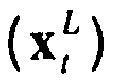
- an error state form

- The position of the origin of the estimated local coordinate reference frame relative to an origin of the global coordinate reference frame may be known/estimated. A position of the origin of the correction-free local coordinate reference frame relative to the origin of the estimated local coordinate reference frame may be known/estimated. The state vector computed can result in the data contained in the local reference frame being robust to the effects of global corrections, but still maintained consistently with respect to those corrections.
- The position of the device in the correction-free local coordinate frame can be formally independent of estimated quantities used in state vector computation.
- If the origin of the global coordinate reference frame is not co-incident with the origin of the estimated local coordinate frame then the vector state may further be defined by a vector describing relative positions of these origins.
- The computation of an estimate of the state vector may implement a SLAM-type algorithm. The SLAM-type algorithm may involve an Extended Kalman filter.
- According to yet another aspect of the present invention there is provided a computer program product comprising a computer readable medium, having thereon computer program code means, when the program code is loaded, to make the computer execute a method of estimating a state of a device and at least one target in an environment (and a method of estimating a position of a device with respect to a global coordinate reference frame) substantially as described herein.
According to another aspect of the present invention there is provided
apparatus configured to estimate a position of a device (100) and at least one target (206A, 206B) in an environment, the apparatus including a device (102) configured to define a global coordinate reference frame, an estimated local coordinate reference frame based on a position of the device, and a correction-free local coordinate reference frame in which the position of the device is assumed to be error-free, further configured to compute a state vector defined by: - a vector

- a vector

- an error state form

- characterised in that the origin of the correction-free coordinate reference frame is defined such that a vector representing the position of the device in the correction-free coordinate reference frame is equal to a vector representing the position of the device in the estimated local reference frame.
- The apparatus may include at least one sensor taking measurements relative to the device, e.g. distance to a said target. The sensor may include a RADAR or LIDAR device. The at least one sensor and/or the processor device will typically be mounted onboard the device.
- The apparatus may further include a device for receiving information relative to the global coordinate reference frame, for example a device configured to receive a GPS locating signal.
- According to an alternative aspect of the present invention there is provided a vehicle including apparatus configured to estimate a position of a vehicle and at least one target in an environment substantially as described herein.
- According to yet another aspect of the present invention there is provided a method of estimating a state of a device and at least one target in an environment, the method including computing a state vector of a device and at least one target using an error state form of a position of the device in a local coordinate reference frame.
- The invention may be performed in various ways, and, by way of example only, embodiments thereof will now be described, reference being made to the accompanying drawings in which:
-
Figure 1 is a block diagram of a vehicle fitted with at least one onboard sensor; -
Figures 2A and 2B illustrate schematically a vehicle using global and local measurements, respectively, in the context of path-based motion control; -
Figure 3 shows a construction including an estimated local coordinate reference frame and a global coordinate reference frame; -
Figure 4 shows a construction including an "error-free" local coordinate reference frame, and -
Figures 5A and 5B are flowcharts showing operations performed by computing device onboard the vehicle in order to estimate positions of the vehicle and at least one target. -
Figure 1 shows avehicle 100 that is fitted with a computing device including aprocessor 102 andmemory 104. The vehicle will also include other conventional features, e.g. steering and traction components, and may be at least partially automated, or can include a planning system for assisting a human operator. The vehicle will also typically include communications devices for communicating with external systems, including other vehicles. It will be appreciated that a vehicle is only one example of a device that can be used to estimate the position of at least one target in an environment. In alternative embodiments, the device can comprise a hand-held tracking unit with a display for indicating the position of the target(s) to a user, or the device may be incorporated into another type of mechanism. - The
vehicle 100 is further fitted with at least one local onboard sensor. In the example the vehicle has a firstlocal sensor 106A and a secondlocal sensor 106B. The local sensors are configured to take measurements relative to the vehicle, typically to obtain information regarding obstacles/object (which may be static or moving) in the vicinity of the vehicle. Such obstacles/objects shall be called "targets" herein and an example is shown schematically at 105, but it will be understood that a target is not necessarily something at which a weapon is to be fired. Examples of suitable local sensors include RADAR and/or LIDAR type devices and the sensors can produce information regarding the range and/or angle to an object in the environment, but other types of output could be produced, e.g. estimated velocity of a moving object. This information is normally presented with respect to a local coordinate system based on the current position of the vehicle. - In the example, the second
local sensor 106B can be configured to take a measurement relating to how the vehicle has moved with respect to where it was previously located, but it will be understood that in some cases this information can be measured by a single local sensor device in combination with sensing objects in the environment. The output provided by thelocal sensor 106B may be in the form of velocity and turn-rate, acceleration, etc. Alternatively, the computing device onboard thevehicle 100 may be configured to store and process data relating to amodel 107 that is intended to estimate the same types of measurements as the secondlocal sensor 106B above. The skilled person will be familiar with processes such as inertial or constant-velocity models that can be used for this purpose. - The
vehicle 100 further includes adevice 108 for receiving global information. A typical example of this type of information comprises GPS or LORAN (LOng Range Aid to Navigation) that provides an estimate of the location of thevehicle 100 with respect to a global coordinate system, transmitted by anexternal system 110. - The approach used by the embodiments described herein can take advantage of the additional finesse that is made available for tasks by separating the fine-scale motions of the device with respect to local features from the global pose uncertainty. For example, it is not necessary to consider the global location of a vehicle and some gate-posts when navigating through a narrow opening; rather, it can be sufficient to know where the gate-posts are located with respect to the vehicle.
Figures 2A and 2B illustrate qualitative differences between the two approaches. In these Figures the obstacles lie off the global plan (i.e. route traversal will not require reactive deviations from that path), e.g. the planned route is clear of unexpected obstacles such as a parked car in the carriageway. - In
Figure 2A uncertainty in the location ofvehicle 100 is represented by the solidblack ellipse 202 and thetargets black ellipses 


corridor 208. InFigure 2B , however, the global uncertainty is not mapped onto the obstacle locations so while the effective corridor width remains the same

ellipses 206A' and 206B' represent the marginal local uncertainties. To generalise, 206A, 206B inFigures 2A and 2B represent the marginal uncertainties in the frame of reference global inFigure 2A and local inFigure 2B . - In
Figure 2A the control (or mapping, planning, etc) is performed in the global space with respect to the global, marginal uncertainties. The corridor defines a width

targets 204A', 204B' and their uncertainty in location with respect to the vehicle (based on local measurements giving the local marginal uncertainty) is shown by the two small,grey ellipses 206A', 206B'. The obstacle observations are then mapped into the global space, resulting in the larger, black,dotted ellipses 
- In
Figure 2B the control is performed in the local space. The local effective corridor width,
grey ellipses 206A', 206B'); this results in a clear improvement in the traversablewidth 
- In
Figure 2A the uncertainties represented are the marginal projections of the global locations; this must be conservative as the global frame is used (and not the local frame where the differences are taken).Figure 2B uses the local frame and so only the relative uncertainty remains for local data; the global data, however, requires the global position of the vehicle to be subtracted from it. Purely global data (that is, data which does not depend on the current vehicle position) will have no correlation to the vehicle position and the marginal projection is used in exactly the same was as inFigure 2A . If the global map has simultaneously estimated the vehicle position and the location of objects within the environment, then it should be possible to derive the local map from the global data. - In the construction shown in
Figure 3 , it is assumed that the local estimated coordinate reference frame (l) is defied relative to the vehicle (but not any external reference), which represents a special-case of a generic local coordinate frame where the vehicle position, as well as objects within the environment, are represented with respect to an arbitrary local coordinate system (local in the sense that no additional information is needed for the vehicle to use the data; that information would be necessary to communicate the data to another device). The construction represents the vehicle and environmental locations (
vehicle frame 300. If the statistical dependencies are known between the data in the local frame and the data in the global frame (and equivalently between the local and vehicle frames), then it is possible to convert between the different representations without loss of information. - As noted above, estimator corrections (such as those involving sensors used within a control system) can result in apparent step-changes in non-statistical downstream devices' (e.g. for control) error-terms and will necessarily reduce the stability and controllability of the composite system. This suggested to the present inventors that applications sensitive to such effects should be attempted in a space that is "correction-free". It can be demonstrated that the only way in which an estimated quantity can be prevented from being updated following an observation is to have enforced null-dependency with all observed quantities, such as zero-correlation in a Kalman filter. If this is not true, then an update of any dependent quantity will necessarily result in a non-zero impact on the "correction-free" quantity and its value will change.
- It is desired that the vehicle's local position,


-
Figure 4 shows a construction that is intended to address the inconsistency described above with reference toFigure 3 whilst maintaining a useful continuous control space (in which the corrections do not occur) and illustrates the development of a "Correction-free" Local frame. It is firstly assumed that the vehicle position in the local frame is known perfectly. This assumed "error-free" local position is denoted by
Figure 4 by a dashed outline 100' of the vehicle. The solid line construction inFigure 4 is the same as that shown inFigure 3 . - As noted above, this error-free position will be inconsistent with the estimated local position,


triangle 402 inFigure 4 . The error-term (rather than the estimate xv L) can be maintained along with the local frame position and the global position and the vector sum involving these quantities and the error-free position will remain consistent. If the error term is appropriately estimated along with the vehicle's local position, the local frame's global position and the vehicle's global position, then the following vector sum remains consistent:
- This implies that the error-free location can remain correction-free while the estimation scheme remains consistent in the global frame. An alternative interpretation of the error-free position will now be considered. The vector parallelogram (the lower dashed
triangle 404 inFigure 4 ) is constructed with sides equal to the error-free position and the local position error-term. Thelower apex 406 defines the origin of the "Correction-free" Local Frame (L) in which the vehicle position is without error,

upper triangle 402. In order to maintain the consistency of an equation analagous to the one above, the last side of the parallelogram should be recognised as the error of the location of the Correction-free Local frame (L) in the Estimated Local frame (l); by definition this will be equivalent to the position error-term in the estimated local frame,
- A one-dimensional analogue of the construction described above will be considered below using the global SLAM problem ("traditional SLAM"), and then followed using the Correction-free Local Frame.
- In the global SLAM Model the state vector will be defined by:

- Assume a simple dynamics model where the update equations for the system are given by:


- The initial covariance matrix for this example is derived from the definition of the target position,


- In the Correction-free Local Frame SLAM Model, the state vector will be defined by:




- In this case, the initial covariance matrix is constructed using the two relationships:


- Note that the global SLAM construct can be derived from the error-free local version using the following 'observation' mechanism:


Figure 4 . - Observation of the global vehicle position can readily be incorporated into this model using the observation mechanism:


-
Figures 5A and 5B illustrate steps performed by the computing device onboard thevehicle 100 in order to implement the computations described above to generate state information, which can include an indication of the location (e.g. X, Y coordinates with respect to the global coordinate system, although other types of positional information could be generated) of the vehicle as well as one or more targets in the environment. The overall computation can be divided into a correction-free part (involving a computation of the position of the vehicle/target(s) with respect to the local frame that is assumed to be error-free) and an estimated part. In some embodiments, more than one processor may be used to perform the computations. It is also possible for at least part of the computation to be performed remotely, with the result being transmitted to a processor onboard the vehicle for further processing, e.g. implementing a vehicle manoeuvre. -
Figure 5A shows steps performed in connection with the error-free part of the process. Atstep 502A data representing the initial/previous value of the state is obtained. Here, the state is considered to be the error-free position of the vehicle and target(s) with respect to the correction-free local frame coordinate system because it is based on a measurement of the vehicle/target(s) positions that is assumed to be correct. Atstep 504A that data is used by a prediction process, e.g. a predict step from a Kalman filter (alternatively, Extended Kalman Filter, Particle Filter or Bayes Filter could be used), in most cases along with a measurement taken by the at least one local sensor (e.g. 106A, 106B) fitted on the vehicle and theprediction model 107. Alternatively, the information may be obtained from a global sensor, e.g. 108. The measurement typically comprises an indication of the position of the vehicle/target(s) in terms of the local coordinate system and, again, is considered to be error-free. Atstep 506A data representing the current state output bystep 504A is obtained and control returns to step 502A, with the current state replacing the previous state. The values involved in the process ofFigure 5A have uncertainty, but the process does not track/deal with this uncertainly; instead, this is done by the process ofFigure 5B . - Turning to
Figure 5B , atstep 502B data representing the initial/current state is obtained. Here, the state is an estimate of the position of the vehicle with respect to the global frame coordinate system and will include an element of uncertainty. Atstep 504B that data is used in a prediction process, e.g. the predict step of a Kalman filter, along with a measurement taken by the at least one local sensor (e.g. 106A, 106B, which may include an inertial unit or the like) and theprediction model 107. Alternatively, the information may be obtained from a global sensor,e.g. sensor 108. Atstep 506B data representing the current state output bystep 504B is obtained and control may return to step 502B, with the current state replacing the previous state. - Step 508B shows an update process that uses a measurement received via the
device 108 for receiving global information and theprediction model 107. Alternatively, the information may be obtained from at least one local data-obtaining sensor,e.g. sensor step 506B (before control returns to step 502B), as depicted byarrow 505, or asynchronously as depicted by arrow 505'. Atstep 510B an updated value is obtained and control returns to step 502B, with the updated state replacing the previous state.
Claims (14)
- A method of estimating a position of a device (100) and at least one target (204A, 204B) in an environment, the method including defining a global coordinate reference frame, an estimated local coordinate reference frame, and a correction-free local coordinate reference frame in which the position of the device is assumed to be error-free, and the method further including computing a state vector defined by:a vector
 a vector
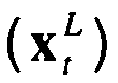 an error state form
 characterised in thatthe origin of the correction-free coordinate reference frame is defined such that a vector representing the position of the device in the correction-free coordinate reference frame is equal to a vector representing the estimated position of the device in the estimated local coordinate reference frame.
 - A method according to claim 1, wherein the position of the device (100) in the correction-free local coordinate frame (L) is formally independent of estimated quantities used in the state vector computation.
- A method according to claim 1 or 2, wherein if the origin of the global coordinate reference frame (g) is not co-incident with the origin of the estimated local coordinate frame (l) then the vector state is further defined by a vector (xg l) describing relative positions of these origins.
- A method according to any one of claims 1 to 3, wherein the computation implements a SLAM-type algorithm.
- A method according to any one of claims 1 to 4, wherein the device (100) comprises a first onboard sensor (106A) configured for taking measurements relating to said target in a vicinity of the device (100); and wherein the method further comprises the step of receiving information from the first onboard sensor and using the received information to determine a vector representing a position of the said target in the correction free local coordinate reference frame.
- A method according to any one of claims 1 to 5, wherein the device (100) further comprises a second onboard sensor configured to take measurements relating to how the device has moved with respect to a previous location of the device; and wherein the method further comprises the step of receiving information from the second onboard sensor and using the received information deterministically to calculate a position of the device in the correction free local coordinate reference frame.
- A method according to any one of claims 1 to 6 further comprising the step of receiving, via means onboard the device, information relative to the global coordinate reference frame.
- A computer program product comprising a computer readable medium, having thereon computer program code means, when the program code is loaded, to make the computer execute a method of estimating a state of a device and at least one target in an environment according to any one of the preceding claims.
- Apparatus configured to estimate a position of a device (100) and at least one target (206A, 206B) in an environment, the apparatus including a device (102) configured to define a global coordinate reference frame, an estimated local coordinate reference frame, and a correction-free local coordinate reference frame in which the position of the device is assumed to be error-free, further configured to compute a state vector defined by:a vector
 a vector
 an error state form
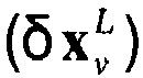 characterised in thatthe origin of the correction-free coordinate reference frame is defined such that a vector representing the position of the device in the correction-free coordinate reference frame is equal to a vector representing the estimated position of the device in the estimated local coordinate reference frame.
 - Apparatus according to claim 9, including at least one sensor (106A, 106B) for taking measurements relating to a said target in a vicinity of the device (100).
- Apparatus according to claim 10, wherein the at least one sensor (106A, 106B) is mounted onboard the device (100).
- Apparatus according to any one of claims 9 to 11, further including a device (108) for receiving information relative to the global coordinate reference frame.
- Apparatus according to claim 12, wherein the device (108) for receiving global information is configured to receive a GPS locating signal.
- A vehicle (100) including apparatus according to any one of claims 9 to 13.
Priority Applications (2)
| Application Number | Priority Date | Filing Date | Title |
|---|---|---|---|
| EP10735331.0A EP2460059B1 (en) | 2009-07-28 | 2010-07-22 | Estimating positions of a device and at least one target in an environment |
| PL10735331T PL2460059T3 (en) | 2009-07-28 | 2010-07-22 | Estimating positions of a device and at least one target in an environment |
Applications Claiming Priority (4)
| Application Number | Priority Date | Filing Date | Title |
|---|---|---|---|
| GB0913078A GB0913078D0 (en) | 2009-07-28 | 2009-07-28 | Estimating positions of a device and at least one target in an environment |
| EP09275054A EP2287698A1 (en) | 2009-07-28 | 2009-07-28 | Estimating positions of a device and at least one target in an environment |
| PCT/GB2010/051210 WO2011012882A1 (en) | 2009-07-28 | 2010-07-22 | Estimating positions of a device and at least one target in an environment |
| EP10735331.0A EP2460059B1 (en) | 2009-07-28 | 2010-07-22 | Estimating positions of a device and at least one target in an environment |
Publications (2)
| Publication Number | Publication Date |
|---|---|
| EP2460059A1 EP2460059A1 (en) | 2012-06-06 |
| EP2460059B1 true EP2460059B1 (en) | 2018-09-05 |
Family
ID=42753269
Family Applications (1)
| Application Number | Title | Priority Date | Filing Date |
|---|---|---|---|
| EP10735331.0A Active EP2460059B1 (en) | 2009-07-28 | 2010-07-22 | Estimating positions of a device and at least one target in an environment |
Country Status (5)
| Country | Link |
|---|---|
| US (1) | US8831880B2 (en) |
| EP (1) | EP2460059B1 (en) |
| ES (1) | ES2706123T3 (en) |
| PL (1) | PL2460059T3 (en) |
| WO (1) | WO2011012882A1 (en) |
Families Citing this family (17)
| Publication number | Priority date | Publication date | Assignee | Title |
|---|---|---|---|---|
| CN103123727B (en) * | 2011-11-21 | 2015-12-09 | 联想(北京)有限公司 | Instant location and map constructing method and equipment |
| US9342888B2 (en) | 2014-02-08 | 2016-05-17 | Honda Motor Co., Ltd. | System and method for mapping, localization and pose correction of a vehicle based on images |
| US20150373293A1 (en) * | 2014-06-24 | 2015-12-24 | Sony Corporation | Video acquisition with adaptive frame rate |
| DE102014111126A1 (en) * | 2014-08-05 | 2016-02-11 | Valeo Schalter Und Sensoren Gmbh | Method for generating an environment map of an environmental area of a motor vehicle, driver assistance system and motor vehicle |
| CN104850131A (en) * | 2015-04-21 | 2015-08-19 | 北京理工大学 | Robot team formation control method based on position estimation |
| WO2018031678A1 (en) * | 2016-08-09 | 2018-02-15 | Nauto Global Limited | System and method for precision localization and mapping |
| US10048753B1 (en) * | 2017-04-20 | 2018-08-14 | Robert C. Brooks | Perspective or gaze based visual identification and location system |
| WO2018222124A1 (en) | 2017-06-01 | 2018-12-06 | Terranet Ab | Vehicular self-positioning |
| US10453150B2 (en) | 2017-06-16 | 2019-10-22 | Nauto, Inc. | System and method for adverse vehicle event determination |
| EP3506040B8 (en) * | 2017-12-28 | 2021-09-22 | Einride AB | Cooperative sensing |
| US11392131B2 (en) | 2018-02-27 | 2022-07-19 | Nauto, Inc. | Method for determining driving policy |
| CN109974704B (en) * | 2019-03-01 | 2021-01-08 | 深圳市智能机器人研究院 | Robot capable of calibrating global positioning and local positioning and control method thereof |
| US12130635B2 (en) * | 2019-09-13 | 2024-10-29 | Sony Group Corporation | Information processing system and information processing apparatus |
| SE2050260A1 (en) | 2020-03-09 | 2021-09-10 | Einride Ab | Method for controlling a fleet of autonomous/remotely operated vehicles |
| CN113492882B (en) * | 2021-07-14 | 2022-09-23 | 清华大学 | Method and device for realizing vehicle control, computer storage medium and terminal |
| US20230166759A1 (en) * | 2021-12-01 | 2023-06-01 | Toyota Research Institute, Inc. | Systems and methods for improving localization accuracy by sharing dynamic object localization information |
| CN115696568A (en) * | 2022-10-27 | 2023-02-03 | 北京经纬恒润科技股份有限公司 | Vehicle positioning method, device and system |
Family Cites Families (7)
| Publication number | Priority date | Publication date | Assignee | Title |
|---|---|---|---|---|
| US7962285B2 (en) | 1997-10-22 | 2011-06-14 | Intelligent Technologies International, Inc. | Inertial measurement unit for aircraft |
| US6408245B1 (en) | 2000-08-03 | 2002-06-18 | American Gnc Corporation | Filtering mechanization method of integrating global positioning system receiver with inertial measurement unit |
| US6879875B1 (en) * | 2003-09-20 | 2005-04-12 | American Gnc Corporation | Low cost multisensor high precision positioning and data integrated method and system thereof |
| US7395156B2 (en) | 2005-06-23 | 2008-07-01 | Raytheon Company | System and method for geo-registration with global positioning and inertial navigation |
| US20080091352A1 (en) | 2006-10-11 | 2008-04-17 | O'hare James K | Automobile collision avoidance system |
| EP2302407B1 (en) * | 2006-11-06 | 2012-08-29 | TomTom Global Content B.V. | Arrangement for and method of two dimensional and three dimensional precision location and orientation determination. |
| GB0625244D0 (en) | 2006-12-19 | 2007-01-24 | Qinetiq Ltd | GPS corrections |
-
2010
- 2010-07-22 US US13/387,523 patent/US8831880B2/en active Active
- 2010-07-22 EP EP10735331.0A patent/EP2460059B1/en active Active
- 2010-07-22 PL PL10735331T patent/PL2460059T3/en unknown
- 2010-07-22 WO PCT/GB2010/051210 patent/WO2011012882A1/en not_active Ceased
- 2010-07-22 ES ES10735331T patent/ES2706123T3/en active Active
Also Published As
| Publication number | Publication date |
|---|---|
| WO2011012882A1 (en) | 2011-02-03 |
| PL2460059T3 (en) | 2018-12-31 |
| US8831880B2 (en) | 2014-09-09 |
| ES2706123T3 (en) | 2019-03-27 |
| US20120122486A1 (en) | 2012-05-17 |
| EP2460059A1 (en) | 2012-06-06 |
Similar Documents
| Publication | Publication Date | Title |
|---|---|---|
| US8831880B2 (en) | Estimating positions of a device and at least one target in an environment | |
| US12529563B2 (en) | Vision-aided inertial navigation | |
| US10409233B2 (en) | Method with quasi-Newton Jacobian updates for nonlinear predictive control | |
| CN110554376A (en) | Radar range finding method for vehicles | |
| EP1548534B1 (en) | Method and apparatus for using rotational movement amount of mobile device and computer-readable recording medium for storing computer program | |
| US12092458B2 (en) | System and process for correcting gyroscope drift for a motor vehicle | |
| CN105333869A (en) | Unmanned reconnaissance aerial vehicle synchronous positioning and picture compositing method based on self-adaption EKF | |
| US12215976B2 (en) | Estimation device, estimation method, program product for estimation | |
| CN119860786A (en) | Positioning reliability judging method, system and medium | |
| EP2287698A1 (en) | Estimating positions of a device and at least one target in an environment | |
| CN110637209A (en) | Method, apparatus, and computer-readable storage medium with instructions for estimating the pose of a motor vehicle | |
| Glavine et al. | Gps integrated inertial navigation system using interactive multiple model extended kalman filtering | |
| US11613272B2 (en) | Lane uncertainty modeling and tracking in a vehicle | |
| US11756312B2 (en) | Orientation-agnostic lane tracking in a vehicle | |
| KR20190079470A (en) | Method and apparatus for determining object position | |
| Wang et al. | Visual regulation of a nonholonomic wheeled mobile robot with two points using Lyapunov functions | |
| Zhang et al. | Variational Bayesian Based Adaptive CKF-SLAM Algorithm under Non-steady Noise | |
| CN119936940B (en) | Automatic driving vehicle accumulated error reduction method based on Kalman filtering | |
| Oubouabdellah et al. | Localization and Navigation of an Autonomous Vehicle in Case of GPS Signal Loss | |
| Ryu et al. | Indoor Pedestrian-Following System by a Drone with Edge Computing and Neural Networks: Part 1-System Design | |
| KR20250138645A (en) | Operation control system for autonomous marine mobility and its precise positioning method | |
| CN118464048A (en) | Vehicle reference line generation method and device, vehicle control terminal and storage medium | |
| EP4723866A1 (en) | Three-dimensional steering of wheeled machines moving over an non-even surface | |
| Webster | A localization solution for an autonomous vehicle in an urban environment | |
| Shrotriya | Robot path planning and tracking of a moving target using Kalman filter |
Legal Events
| Date | Code | Title | Description |
|---|---|---|---|
| PUAI | Public reference made under article 153(3) epc to a published international application that has entered the european phase |
Free format text: ORIGINAL CODE: 0009012 |
|
| 17P | Request for examination filed |
Effective date: 20120124 |
|
| AK | Designated contracting states |
Kind code of ref document: A1 Designated state(s): AL AT BE BG CH CY CZ DE DK EE ES FI FR GB GR HR HU IE IS IT LI LT LU LV MC MK MT NL NO PL PT RO SE SI SK SM TR |
|
| DAX | Request for extension of the european patent (deleted) | ||
| 17Q | First examination report despatched |
Effective date: 20130722 |
|
| GRAP | Despatch of communication of intention to grant a patent |
Free format text: ORIGINAL CODE: EPIDOSNIGR1 |
|
| STAA | Information on the status of an ep patent application or granted ep patent |
Free format text: STATUS: GRANT OF PATENT IS INTENDED |
|
| INTG | Intention to grant announced |
Effective date: 20180406 |
|
| GRAS | Grant fee paid |
Free format text: ORIGINAL CODE: EPIDOSNIGR3 |
|
| GRAA | (expected) grant |
Free format text: ORIGINAL CODE: 0009210 |
|
| STAA | Information on the status of an ep patent application or granted ep patent |
Free format text: STATUS: THE PATENT HAS BEEN GRANTED |
|
| AK | Designated contracting states |
Kind code of ref document: B1 Designated state(s): AL AT BE BG CH CY CZ DE DK EE ES FI FR GB GR HR HU IE IS IT LI LT LU LV MC MK MT NL NO PL PT RO SE SI SK SM TR |
|
| REG | Reference to a national code |
Ref country code: GB Ref legal event code: FG4D |
|
| REG | Reference to a national code |
Ref country code: CH Ref legal event code: EP |
|
| REG | Reference to a national code |
Ref country code: AT Ref legal event code: REF Ref document number: 1038556 Country of ref document: AT Kind code of ref document: T Effective date: 20180915 |
|
| REG | Reference to a national code |
Ref country code: DE Ref legal event code: R096 Ref document number: 602010053315 Country of ref document: DE |
|
| REG | Reference to a national code |
Ref country code: IE Ref legal event code: FG4D |
|
| REG | Reference to a national code |
Ref country code: EE Ref legal event code: FG4A Ref document number: E016328 Country of ref document: EE Effective date: 20181001 |
|
| REG | Reference to a national code |
Ref country code: NL Ref legal event code: MP Effective date: 20180905 |
|
| REG | Reference to a national code |
Ref country code: LT Ref legal event code: MG4D |
|
| PG25 | Lapsed in a contracting state [announced via postgrant information from national office to epo] |
Ref country code: FI Free format text: LAPSE BECAUSE OF FAILURE TO SUBMIT A TRANSLATION OF THE DESCRIPTION OR TO PAY THE FEE WITHIN THE PRESCRIBED TIME-LIMIT Effective date: 20180905 Ref country code: SE Free format text: LAPSE BECAUSE OF FAILURE TO SUBMIT A TRANSLATION OF THE DESCRIPTION OR TO PAY THE FEE WITHIN THE PRESCRIBED TIME-LIMIT Effective date: 20180905 Ref country code: GR Free format text: LAPSE BECAUSE OF FAILURE TO SUBMIT A TRANSLATION OF THE DESCRIPTION OR TO PAY THE FEE WITHIN THE PRESCRIBED TIME-LIMIT Effective date: 20181206 Ref country code: NO Free format text: LAPSE BECAUSE OF FAILURE TO SUBMIT A TRANSLATION OF THE DESCRIPTION OR TO PAY THE FEE WITHIN THE PRESCRIBED TIME-LIMIT Effective date: 20181205 Ref country code: LT Free format text: LAPSE BECAUSE OF FAILURE TO SUBMIT A TRANSLATION OF THE DESCRIPTION OR TO PAY THE FEE WITHIN THE PRESCRIBED TIME-LIMIT Effective date: 20180905 Ref country code: BG Free format text: LAPSE BECAUSE OF FAILURE TO SUBMIT A TRANSLATION OF THE DESCRIPTION OR TO PAY THE FEE WITHIN THE PRESCRIBED TIME-LIMIT Effective date: 20181205 |
|
| REG | Reference to a national code |
Ref country code: AT Ref legal event code: MK05 Ref document number: 1038556 Country of ref document: AT Kind code of ref document: T Effective date: 20180905 |
|
| PG25 | Lapsed in a contracting state [announced via postgrant information from national office to epo] |
Ref country code: HR Free format text: LAPSE BECAUSE OF FAILURE TO SUBMIT A TRANSLATION OF THE DESCRIPTION OR TO PAY THE FEE WITHIN THE PRESCRIBED TIME-LIMIT Effective date: 20180905 Ref country code: LV Free format text: LAPSE BECAUSE OF FAILURE TO SUBMIT A TRANSLATION OF THE DESCRIPTION OR TO PAY THE FEE WITHIN THE PRESCRIBED TIME-LIMIT Effective date: 20180905 Ref country code: AL Free format text: LAPSE BECAUSE OF FAILURE TO SUBMIT A TRANSLATION OF THE DESCRIPTION OR TO PAY THE FEE WITHIN THE PRESCRIBED TIME-LIMIT Effective date: 20180905 |
|
| REG | Reference to a national code |
Ref country code: ES Ref legal event code: FG2A Ref document number: 2706123 Country of ref document: ES Kind code of ref document: T3 Effective date: 20190327 |
|
| PG25 | Lapsed in a contracting state [announced via postgrant information from national office to epo] |
Ref country code: AT Free format text: LAPSE BECAUSE OF FAILURE TO SUBMIT A TRANSLATION OF THE DESCRIPTION OR TO PAY THE FEE WITHIN THE PRESCRIBED TIME-LIMIT Effective date: 20180905 Ref country code: CZ Free format text: LAPSE BECAUSE OF FAILURE TO SUBMIT A TRANSLATION OF THE DESCRIPTION OR TO PAY THE FEE WITHIN THE PRESCRIBED TIME-LIMIT Effective date: 20180905 Ref country code: NL Free format text: LAPSE BECAUSE OF FAILURE TO SUBMIT A TRANSLATION OF THE DESCRIPTION OR TO PAY THE FEE WITHIN THE PRESCRIBED TIME-LIMIT Effective date: 20180905 Ref country code: RO Free format text: LAPSE BECAUSE OF FAILURE TO SUBMIT A TRANSLATION OF THE DESCRIPTION OR TO PAY THE FEE WITHIN THE PRESCRIBED TIME-LIMIT Effective date: 20180905 Ref country code: IS Free format text: LAPSE BECAUSE OF FAILURE TO SUBMIT A TRANSLATION OF THE DESCRIPTION OR TO PAY THE FEE WITHIN THE PRESCRIBED TIME-LIMIT Effective date: 20190105 |
|
| PG25 | Lapsed in a contracting state [announced via postgrant information from national office to epo] |
Ref country code: PT Free format text: LAPSE BECAUSE OF FAILURE TO SUBMIT A TRANSLATION OF THE DESCRIPTION OR TO PAY THE FEE WITHIN THE PRESCRIBED TIME-LIMIT Effective date: 20190105 Ref country code: SK Free format text: LAPSE BECAUSE OF FAILURE TO SUBMIT A TRANSLATION OF THE DESCRIPTION OR TO PAY THE FEE WITHIN THE PRESCRIBED TIME-LIMIT Effective date: 20180905 Ref country code: SM Free format text: LAPSE BECAUSE OF FAILURE TO SUBMIT A TRANSLATION OF THE DESCRIPTION OR TO PAY THE FEE WITHIN THE PRESCRIBED TIME-LIMIT Effective date: 20180905 |
|
| REG | Reference to a national code |
Ref country code: DE Ref legal event code: R097 Ref document number: 602010053315 Country of ref document: DE |
|
| PLBE | No opposition filed within time limit |
Free format text: ORIGINAL CODE: 0009261 |
|
| STAA | Information on the status of an ep patent application or granted ep patent |
Free format text: STATUS: NO OPPOSITION FILED WITHIN TIME LIMIT |
|
| PG25 | Lapsed in a contracting state [announced via postgrant information from national office to epo] |
Ref country code: DK Free format text: LAPSE BECAUSE OF FAILURE TO SUBMIT A TRANSLATION OF THE DESCRIPTION OR TO PAY THE FEE WITHIN THE PRESCRIBED TIME-LIMIT Effective date: 20180905 |
|
| 26N | No opposition filed |
Effective date: 20190606 |
|
| PG25 | Lapsed in a contracting state [announced via postgrant information from national office to epo] |
Ref country code: SI Free format text: LAPSE BECAUSE OF FAILURE TO SUBMIT A TRANSLATION OF THE DESCRIPTION OR TO PAY THE FEE WITHIN THE PRESCRIBED TIME-LIMIT Effective date: 20180905 |
|
| PG25 | Lapsed in a contracting state [announced via postgrant information from national office to epo] |
Ref country code: MC Free format text: LAPSE BECAUSE OF FAILURE TO SUBMIT A TRANSLATION OF THE DESCRIPTION OR TO PAY THE FEE WITHIN THE PRESCRIBED TIME-LIMIT Effective date: 20180905 |
|
| REG | Reference to a national code |
Ref country code: CH Ref legal event code: PL |
|
| PG25 | Lapsed in a contracting state [announced via postgrant information from national office to epo] |
Ref country code: TR Free format text: LAPSE BECAUSE OF FAILURE TO SUBMIT A TRANSLATION OF THE DESCRIPTION OR TO PAY THE FEE WITHIN THE PRESCRIBED TIME-LIMIT Effective date: 20180905 |
|
| REG | Reference to a national code |
Ref country code: BE Ref legal event code: MM Effective date: 20190731 |
|
| PG25 | Lapsed in a contracting state [announced via postgrant information from national office to epo] |
Ref country code: BE Free format text: LAPSE BECAUSE OF NON-PAYMENT OF DUE FEES Effective date: 20190731 Ref country code: CH Free format text: LAPSE BECAUSE OF NON-PAYMENT OF DUE FEES Effective date: 20190731 Ref country code: LI Free format text: LAPSE BECAUSE OF NON-PAYMENT OF DUE FEES Effective date: 20190731 Ref country code: LU Free format text: LAPSE BECAUSE OF NON-PAYMENT OF DUE FEES Effective date: 20190722 |
|
| PG25 | Lapsed in a contracting state [announced via postgrant information from national office to epo] |
Ref country code: IE Free format text: LAPSE BECAUSE OF NON-PAYMENT OF DUE FEES Effective date: 20190722 |
|
| PG25 | Lapsed in a contracting state [announced via postgrant information from national office to epo] |
Ref country code: CY Free format text: LAPSE BECAUSE OF FAILURE TO SUBMIT A TRANSLATION OF THE DESCRIPTION OR TO PAY THE FEE WITHIN THE PRESCRIBED TIME-LIMIT Effective date: 20180905 |
|
| REG | Reference to a national code |
Ref country code: EE Ref legal event code: HC1A Ref document number: E016328 Country of ref document: EE |
|
| PG25 | Lapsed in a contracting state [announced via postgrant information from national office to epo] |
Ref country code: MT Free format text: LAPSE BECAUSE OF FAILURE TO SUBMIT A TRANSLATION OF THE DESCRIPTION OR TO PAY THE FEE WITHIN THE PRESCRIBED TIME-LIMIT Effective date: 20180905 Ref country code: HU Free format text: LAPSE BECAUSE OF FAILURE TO SUBMIT A TRANSLATION OF THE DESCRIPTION OR TO PAY THE FEE WITHIN THE PRESCRIBED TIME-LIMIT; INVALID AB INITIO Effective date: 20100722 |
|
| PG25 | Lapsed in a contracting state [announced via postgrant information from national office to epo] |
Ref country code: MK Free format text: LAPSE BECAUSE OF FAILURE TO SUBMIT A TRANSLATION OF THE DESCRIPTION OR TO PAY THE FEE WITHIN THE PRESCRIBED TIME-LIMIT Effective date: 20180905 |
|
| REG | Reference to a national code |
Ref country code: DE Ref legal event code: R079 Ref document number: 602010053315 Country of ref document: DE Free format text: PREVIOUS MAIN CLASS: G05D0001020000 Ipc: G05D0001430000 |
|
| PGFP | Annual fee paid to national office [announced via postgrant information from national office to epo] |
Ref country code: PL Payment date: 20250625 Year of fee payment: 16 |
|
| PGFP | Annual fee paid to national office [announced via postgrant information from national office to epo] |
Ref country code: GB Payment date: 20250619 Year of fee payment: 16 |
|
| PGFP | Annual fee paid to national office [announced via postgrant information from national office to epo] |
Ref country code: FR Payment date: 20250620 Year of fee payment: 16 Ref country code: EE Payment date: 20250626 Year of fee payment: 16 |
|
| PGFP | Annual fee paid to national office [announced via postgrant information from national office to epo] |
Ref country code: ES Payment date: 20250801 Year of fee payment: 16 |
|
| PGFP | Annual fee paid to national office [announced via postgrant information from national office to epo] |
Ref country code: DE Payment date: 20250620 Year of fee payment: 16 |
|
| PGFP | Annual fee paid to national office [announced via postgrant information from national office to epo] |
Ref country code: IT Payment date: 20250619 Year of fee payment: 16 |