EP2459820B1 - Post mounting footing - Google Patents
Post mounting footing Download PDFInfo
- Publication number
- EP2459820B1 EP2459820B1 EP10755207.7A EP10755207A EP2459820B1 EP 2459820 B1 EP2459820 B1 EP 2459820B1 EP 10755207 A EP10755207 A EP 10755207A EP 2459820 B1 EP2459820 B1 EP 2459820B1
- Authority
- EP
- European Patent Office
- Prior art keywords
- post mounting
- parts
- hinge
- mounting footing
- lower parts
- Prior art date
- Legal status (The legal status is an assumption and is not a legal conclusion. Google has not performed a legal analysis and makes no representation as to the accuracy of the status listed.)
- Active
Links
Images
Classifications
-
- E—FIXED CONSTRUCTIONS
- E04—BUILDING
- E04H—BUILDINGS OR LIKE STRUCTURES FOR PARTICULAR PURPOSES; SWIMMING OR SPLASH BATHS OR POOLS; MASTS; FENCING; TENTS OR CANOPIES, IN GENERAL
- E04H12/00—Towers; Masts or poles; Chimney stacks; Water-towers; Methods of erecting such structures
- E04H12/22—Sockets or holders for poles or posts
- E04H12/2284—Means for adjusting the orientation of the post or pole
-
- E—FIXED CONSTRUCTIONS
- E01—CONSTRUCTION OF ROADS, RAILWAYS, OR BRIDGES
- E01F—ADDITIONAL WORK, SUCH AS EQUIPPING ROADS OR THE CONSTRUCTION OF PLATFORMS, HELICOPTER LANDING STAGES, SIGNS, SNOW FENCES, OR THE LIKE
- E01F9/00—Arrangement of road signs or traffic signals; Arrangements for enforcing caution
- E01F9/60—Upright bodies, e.g. marker posts or bollards; Supports for road signs
- E01F9/623—Upright bodies, e.g. marker posts or bollards; Supports for road signs characterised by form or by structural features, e.g. for enabling displacement or deflection
- E01F9/646—Upright bodies, e.g. marker posts or bollards; Supports for road signs characterised by form or by structural features, e.g. for enabling displacement or deflection extensible, collapsible or pivotable
-
- E—FIXED CONSTRUCTIONS
- E04—BUILDING
- E04G—SCAFFOLDING; FORMS; SHUTTERING; BUILDING IMPLEMENTS OR AIDS, OR THEIR USE; HANDLING BUILDING MATERIALS ON THE SITE; REPAIRING, BREAKING-UP OR OTHER WORK ON EXISTING BUILDINGS
- E04G21/00—Preparing, conveying, or working-up building materials or building elements in situ; Other devices or measures for constructional work
- E04G21/32—Safety or protective measures for persons during the construction of buildings
- E04G21/3204—Safety or protective measures for persons during the construction of buildings against falling down
- E04G21/3214—Means for working on roofs
-
- E—FIXED CONSTRUCTIONS
- E04—BUILDING
- E04G—SCAFFOLDING; FORMS; SHUTTERING; BUILDING IMPLEMENTS OR AIDS, OR THEIR USE; HANDLING BUILDING MATERIALS ON THE SITE; REPAIRING, BREAKING-UP OR OTHER WORK ON EXISTING BUILDINGS
- E04G21/00—Preparing, conveying, or working-up building materials or building elements in situ; Other devices or measures for constructional work
- E04G21/32—Safety or protective measures for persons during the construction of buildings
- E04G21/3204—Safety or protective measures for persons during the construction of buildings against falling down
- E04G21/3223—Means supported by building floors or flat roofs, e.g. safety railings
-
- E—FIXED CONSTRUCTIONS
- E04—BUILDING
- E04G—SCAFFOLDING; FORMS; SHUTTERING; BUILDING IMPLEMENTS OR AIDS, OR THEIR USE; HANDLING BUILDING MATERIALS ON THE SITE; REPAIRING, BREAKING-UP OR OTHER WORK ON EXISTING BUILDINGS
- E04G21/00—Preparing, conveying, or working-up building materials or building elements in situ; Other devices or measures for constructional work
- E04G21/32—Safety or protective measures for persons during the construction of buildings
- E04G21/3204—Safety or protective measures for persons during the construction of buildings against falling down
- E04G21/3223—Means supported by building floors or flat roofs, e.g. safety railings
- E04G21/3228—Folding railings for flat roof edge, e.g. to hide the railings from view when not in use
Definitions
- the present invention relates to a post mounting footing and particularly but not exclusively to a post mounting footing for mounting a support post for a guardrail.
- Safety guardrails are known which can be mounted in areas of potential danger, such as for example on roof structures.
- Such guardrails may have support posts mounted in socket footing structures either permanently fixed in position or temporarily.
- Cross members are typically clamped or otherwise secured between adjacent support posts. It is known for such guardrail structures to be hingedly mounted at a hinge footing in order to enable the guardrail to be folded flat from an upright position.
- US6050032 discloses a known safety fence for a square hatched formed in a slab of a building.
- WO2008/019499 discloses a post support assembly for an adjustable safety rail barricade comprised of a flat attachment base plate to which a post is secured.
- GB 2 192 218 A discloses a collapsible barrier assembly with the features of the preamble of claim 1. An improved arrangement has now been devised.
- the present invention provides a post mounting footing, particularly suitable for a guardrail or barrier system, comprising:
- the upper and lower parts are configured to be re-orientatable between a first position in which abutment portions of the upper and lower parts abut one another to inhibit hinge operation; and a second position in which clearance between the abutment portions is enabled so as to permit hinging.
- the upper part is arranged to be displaced upwardly relative to the lower part in order to move from the first position to the second position.
- a preferred feature is that the upper and lower parts are configured to permit hinging through substantially greater than 90 degrees.
- one of the upper and lower parts (preferably the lower part) is provided with a recess having an open upper portion, an open side portion and a closed side portion opposed to the open side portion.
- the other of the upper and lower parts comprises the tongue portion arranged to be received in the recess of the other part.
- a surface of the closed side portion comprises an abutment surface.
- the upper and lower parts hinge such that in the hinged position, one of the parts extends out of the other part through the open side portion.
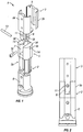
- a post mounting footing 1 comprising a lower base structure 2 and a post receiving upper part 3 arranged to receive a lower end of a post 4 of a guardrail system.
- the base structure includes a lower hinge mounting body 5 which is arranged to be received in a socket base 6.
- the socket base 6 can be bolted or otherwise secured (temporarily o permanently) to a surface or structure to which the guardrail system is mounted.
- the lower hinge body 5 includes a part 5a which is received within the socket base 6, and an upper part 5b provided with a hinge mounting structure.
- the upper part 5b of the lower mounting body 5 is provided with a recess 7 for accommodating a tongue portion 8 of the upper part 3.
- the recess is provided in the upper portion and one side portion 5a of the lower mounting body 5b.
- the other side part 5c of the lower mounting body 5b is closed.
- the upper part 3 of the post mounting footing 1 is of two-part construction and comprises a first shell piece 3 a that co-operates with a second shell piece 3b to define a pair of socket opening 9 shaped to receive a pair of posts 4 in side by side relationship.
- the shell piece 3 a carries the tongue portion 8 extending downwardly.
- the tongue portion 8 is provided with an elongate slot 10 running in an upward and downward direction and extending completely across the width of the tongue portion 8.
- the tongue portion 8 of the upper part 3 also includes a bore 11 extending completely through the tongue portion 8 in a direction transverse to (and intersecting with) the slot 10.
- the end of the bore 11 is provided with a screw thread for threaded engagement with the end of a fixing bolt 12 that fits into the bore 11.
- the other end of the bore 11 is countersunk to receive the head of the fixing bolt.
- the fixing bolt 12 head can be accessed when screwed in by means of an Allen key or other mechanical torque drive tool.
- the upper part 5b of the lower mounting body 5 is provided with a hinge pivot rod 13 which is mounted in respective mounting apertures 14 in upright walls 5d 5e spaced at opposite sides of the recess 7.
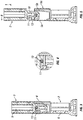
- the post mounting footing 1 is assembled such that the upper part 3 rests in weight bearing contact on the lower mounting body 5 with the tongue 8 at a home position received in the recess 7 of the lower mounting body 5.
- the hinge pivot rod 13 extends through the slot 10 and is positioned at the uppermost extent of the slot 10.
- the fixing bolt 12 is screwed into place extending through the bore11 such that it is positioned immediately below the hinge pivot rod 13. This situation, with the bore 11 positioned to position the bolt 12 immediately below the hinge pivot rod is shown clearly in figures 3 and 4 .
- the tongue 8 is positioned immediately adjacent the internal surface of closed side part 5c.
- the upper part 3 is prevented from pivoting out of the upright orientation by the presence of the fixing bolt 12 and the tongue 8 being is positioned immediately adjacent the internal surface of closed side part 5c.
- the upper part 3 is however capable of pivoting on the hinge pivot rod 13 to the position shown in figures 6 7 and 8 .
- the fixing bolt 12 is first removed from the bore 11 in the upper part 3.
- the hinge pivot rod 13 moves downwardly relative to the slot 10 until it abuts against the bottom end of the slot 10. From this position, the upper part 3 can be pivoted in the direction of arrow B in figure 5 in order to re-orientate the upper part 3 to the post lowered configuration as shown in figures 6 7 and 8 .
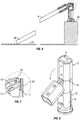
- the upper part is first raised upwardly before pivoting (to provide the clearance of the upper part 3 and tongue 4 from the lower mounting body 5b and slot 7, the upper part can hinge through greater than 90 degrees, enabling the post lowered configuration to position the support post 4 at an angle inclined downwardly from the post mounting footing.
- This is particularly advantageous where the post mounting footing is used on a parapet 20 as shown in figure 6 , because it means that the end 4a of the post 4 can rest on the horizontal surface 21 spaced below the level of the parapet. If the upper part 3 of the post mounting footing 1 could only hinge or pivot through 90 degrees, then the post 4 would extend directly out from the parapet as a cantilevered beam.
- any accidental loading of the cantilevered beam would likely result in buckling of the beam or breakage stress at the post mounting footing.
- the configuration as shown in figure 6 would ensure greater spreading of any loading of the post in the lowered configuration to be spread over more than one loading point at either end of the post.
- the fact that the upper part 3 is required to be lifted in order to re-orientate from the upright position provides added safety benefits because it makes accidental pivoting/hinging more difficult to occur (for example if the bolt 12 is not in place).
Landscapes
- Engineering & Computer Science (AREA)
- Architecture (AREA)
- Civil Engineering (AREA)
- Structural Engineering (AREA)
- Mechanical Engineering (AREA)
- Refuge Islands, Traffic Blockers, Or Guard Fence (AREA)
Description
- The present invention relates to a post mounting footing and particularly but not exclusively to a post mounting footing for mounting a support post for a guardrail.
- Safety guardrails are known which can be mounted in areas of potential danger, such as for example on roof structures. Such guardrails may have support posts mounted in socket footing structures either permanently fixed in position or temporarily. Cross members are typically clamped or otherwise secured between adjacent support posts. It is known for such guardrail structures to be hingedly mounted at a hinge footing in order to enable the guardrail to be folded flat from an upright position.
-
US6050032 discloses a known safety fence for a square hatched formed in a slab of a building.WO2008/019499 discloses a post support assembly for an adjustable safety rail barricade comprised of a flat attachment base plate to which a post is secured.GB 2 192 218 A - The present invention provides a post mounting footing, particularly suitable for a guardrail or barrier system, comprising:
- a lower part;
- an upper part, hinge mounted with respect to the lower part;
- wherein the upper and lower parts are configured to be re-orientatable between a first position in which hinge operation is inhibited; and a second position in which clearance between the upper and lower parts is enabled so as to permit hinging;
- wherein a hinge formation is fixed to one of the upper and lower parts and is received in a slot provided in a tongue portion in the other of the upper and lower parts, the hinge formation being movable along the slot when the upper and lower parts are re-orientated between the first and second position;
- wherein the slot runs in an upward and downward direction and extends completely across the width of the tongue portion; and
- wherein a locking element is received in a bore, the bore extending completely through the tongue portion in a direction transverse to, and intersecting with, the slot, such that the locking element is positionable immediately below the hinge formation to inhibit movement of the hinge formation along the slot, thereby locking the upper and lower parts to prevent the upper and lower parts being re-orientated between the first and second position.
- In one embodiment, it is preferred that the upper and lower parts are configured to be re-orientatable between a first position in which abutment portions of the upper and lower parts abut one another to inhibit hinge operation; and a second position in which clearance between the abutment portions is enabled so as to permit hinging.
- Beneficially, the upper part is arranged to be displaced upwardly relative to the lower part in order to move from the first position to the second position.
- A preferred feature is that the upper and lower parts are configured to permit hinging through substantially greater than 90 degrees.
- It is preferred in certain realisations that, in the first position the upper part rests in load bearing contact on the lower part.
- In a preferred embodiment one of the upper and lower parts (preferably the lower part) is provided with a recess having an open upper portion, an open side portion and a closed side portion opposed to the open side portion. The other of the upper and lower parts comprises the tongue portion arranged to be received in the recess of the other part. Beneficially a surface of the closed side portion comprises an abutment surface.
- In a preferred embodiment the upper and lower parts hinge such that in the hinged position, one of the parts extends out of the other part through the open side portion.
- The invention will now be further described in a specific embodiment by way of example only and with reference to the accompanying drawings, in which:
-
Figure 1 is a perspective exploded view of a Post mounting footing in accordance with the invention; -
Figure 2 is a side view of the post mounting footing offigure 1 ; -
Figure 3 is a sectional view of the post mounting footing offigures 1 and 2 ; -
Figure 4 is a view of detail offigure 3 ; -
Figure 5 is a view, in section of the post mounting footing of the preceding figures in the process of re-orientation from an upright mounting configuration to a lowered configuration; -
Figure 6 is a view, in section of the post mounting footing of the preceding figures re-orientated to a lowered configuration; -
Figure 7 is a detailed view offigure 6 ; -
Figure 8 is a perspective view of the post mounting footing of the preceding figures re-orientated to the lowered configuration. - Referring to the drawings, and initially to
figure 1 , there is shown a post mounting footing 1 comprising alower base structure 2 and a post receivingupper part 3 arranged to receive a lower end of a post 4 of a guardrail system. The base structure includes a lower hinge mounting body 5 which is arranged to be received in asocket base 6. Thesocket base 6 can be bolted or otherwise secured (temporarily o permanently) to a surface or structure to which the guardrail system is mounted. - The lower hinge body 5 includes a
part 5a which is received within thesocket base 6, and anupper part 5b provided with a hinge mounting structure. - The
upper part 5b of the lower mounting body 5 is provided with arecess 7 for accommodating atongue portion 8 of theupper part 3. The recess is provided in the upper portion and oneside portion 5a of thelower mounting body 5b. The other side part 5c of thelower mounting body 5b is closed. - The
upper part 3 of the post mounting footing 1 is of two-part construction and comprises afirst shell piece 3 a that co-operates with asecond shell piece 3b to define a pair of socket opening 9 shaped to receive a pair of posts 4 in side by side relationship. - The
shell piece 3 a carries thetongue portion 8 extending downwardly. Thetongue portion 8 is provided with anelongate slot 10 running in an upward and downward direction and extending completely across the width of thetongue portion 8. Thetongue portion 8 of theupper part 3 also includes abore 11 extending completely through thetongue portion 8 in a direction transverse to (and intersecting with) theslot 10. The end of thebore 11 is provided with a screw thread for threaded engagement with the end of afixing bolt 12 that fits into thebore 11. The other end of thebore 11 is countersunk to receive the head of the fixing bolt. Thefixing bolt 12 head can be accessed when screwed in by means of an Allen key or other mechanical torque drive tool. - The
upper part 5b of the lower mounting body 5 is provided with ahinge pivot rod 13 which is mounted inrespective mounting apertures 14 inupright walls 5d 5e spaced at opposite sides of therecess 7. - The post mounting footing 1 is assembled such that the
upper part 3 rests in weight bearing contact on the lower mounting body 5 with thetongue 8 at a home position received in therecess 7 of the lower mounting body 5. Thehinge pivot rod 13 extends through theslot 10 and is positioned at the uppermost extent of theslot 10. Thefixing bolt 12 is screwed into place extending through the bore11 such that it is positioned immediately below thehinge pivot rod 13. This situation, with thebore 11 positioned to position thebolt 12 immediately below the hinge pivot rod is shown clearly infigures 3 and 4 . In this position thetongue 8 is positioned immediately adjacent the internal surface of closed side part 5c. Theupper part 3 is prevented from pivoting out of the upright orientation by the presence of thefixing bolt 12 and thetongue 8 being is positioned immediately adjacent the internal surface of closed side part 5c. - The
upper part 3 is however capable of pivoting on thehinge pivot rod 13 to the position shown infigures 6 7 and 8 . In order to achieve this, thefixing bolt 12 is first removed from thebore 11 in theupper part 3. This enables theupper part 3 to be displaced from a home or first position, vertically upwardly (arrow A infigure 5 ) such that a major part of thetongue 8 comes out of therecess 7 in thelower mounting body 5b. In so moving to the upwardly displaced (or second position), thehinge pivot rod 13 moves downwardly relative to theslot 10 until it abuts against the bottom end of theslot 10. From this position, theupper part 3 can be pivoted in the direction of arrow B infigure 5 in order to re-orientate theupper part 3 to the post lowered configuration as shown infigures 6 7 and 8 . - Because the upper part is first raised upwardly before pivoting (to provide the clearance of the
upper part 3 and tongue 4 from thelower mounting body 5b andslot 7, the upper part can hinge through greater than 90 degrees, enabling the post lowered configuration to position the support post 4 at an angle inclined downwardly from the post mounting footing. This is particularly advantageous where the post mounting footing is used on aparapet 20 as shown infigure 6 , because it means that theend 4a of the post 4 can rest on thehorizontal surface 21 spaced below the level of the parapet. If theupper part 3 of the post mounting footing 1 could only hinge or pivot through 90 degrees, then the post 4 would extend directly out from the parapet as a cantilevered beam. Any accidental loading of the cantilevered beam would likely result in buckling of the beam or breakage stress at the post mounting footing. In the case of the present invention the configuration as shown infigure 6 would ensure greater spreading of any loading of the post in the lowered configuration to be spread over more than one loading point at either end of the post. - Also the fact that the
upper part 3 is required to be lifted in order to re-orientate from the upright position provides added safety benefits because it makes accidental pivoting/hinging more difficult to occur (for example if thebolt 12 is not in place).
Claims (12)
- A post mounting footing (1) comprising:a lower part (2);an upper part (3), hinge mounted with respect to the lower part (2);wherein the upper and lower parts are configured to be re-orientatable between a first position in which hinge operation is inhibited; and a second position in which clearance between the upper and lower parts is enabled so as to permit hinging;wherein a hinge formation (5) is fixed to one of the upper (3) and lower (2) parts and is received in a slot (10) provided in a tongue portion (8) in the other of the upper (3) and lower (2) parts, the hinge formation (5) being movable along the slot (10) when the upper and lower parts are re-orientated between the first and second position;wherein the slot (10) runs in an upward and downward direction and extends completely across the width of the tongue portion (8); characterized in that a locking element is received in a bore (11), the bore (11) extending completely through the tongue portion (8) in a direction transverse to, and intersecting with, the slot (10), such that the locking element is positionable immediately below the hinge formation (5) to inhibit movement of the hinge formation along the slot (10), thereby locking the upper and lower parts to prevent the upper and lower parts being re-orientated between the first and second position.
- A post mounting footing according to claim 1, wherein; the upper (3) and lower (2) parts are configured to be re-orientatable between a first position in which abutment portions of the upper and lower parts abut one another to inhibit hinge operation; and a second position in which clearance between the abutment portions is enabled so as to permit hinging.
- A post mounting footing according to claim 1 or 2, wherein the upper part (3) is arranged to be displaced upwardly relative to the lower part (2) in order to move from the first position to the second position.
- A post mounting footing according to any preceding claim, wherein the upper (3) and lower (2) parts are configured to permit hinging through substantially greater than 90 degrees.
- A post mounting footing according to any preceding claim, wherein the first position the upper part (3) rests in load bearing contact on the lower part (2).
- A post mounting footing according to claim 1, wherein the locking element comprises a fixing bolt (12) passing through the upper part (3).
- A post mounting footing according to any preceding claim wherein one of the upper and lower parts is provided with a recess (7) having an open upper portion (5b), an open side portion (5a) and a closed side portion (5c) opposed to the open side portion (5a).
- A post mounting footing according to claim 7, wherein;
the tongue portion (8) of the other of the upper and lower parts is arranged to be received in the recess (7) of the other part; and/or
wherein a surface of the closed side portion (5c) comprises an abutment surface. - A post mounting footing according to claim 7 or claim 8, wherein the upper and lower parts hinge such that, in the hinged position, one of the parts extends out of the other part through the open side portion (5a).
- A post mounting footing according to any preceding claim further comprising a socket base (6) for securing to a structure, the socket base (6) being arranged to receive the lower part (5a) of the post mounting footing (5) preferably wherein the lower part includes a part which is received within the socket base, and an upper part (5b), including a hinge formation, positioned upwardly of the socket base (6).
- A mounting footing for a guardrail or barrier system, the mounting footing comprising a footing according to any preceding claim.
- A guardrail or barrier system including one or more post mounting footings according to any of claims 1 to 10.
Applications Claiming Priority (2)
| Application Number | Priority Date | Filing Date | Title |
|---|---|---|---|
| GB0913410.7A GB2472267B (en) | 2009-07-31 | 2009-07-31 | Post mounting footing |
| PCT/GB2010/001452 WO2011012864A1 (en) | 2009-07-31 | 2010-08-02 | Post mounting footing |
Publications (2)
| Publication Number | Publication Date |
|---|---|
| EP2459820A1 EP2459820A1 (en) | 2012-06-06 |
| EP2459820B1 true EP2459820B1 (en) | 2017-11-08 |
Family
ID=41129464
Family Applications (1)
| Application Number | Title | Priority Date | Filing Date |
|---|---|---|---|
| EP10755207.7A Active EP2459820B1 (en) | 2009-07-31 | 2010-08-02 | Post mounting footing |
Country Status (3)
| Country | Link |
|---|---|
| EP (1) | EP2459820B1 (en) |
| GB (1) | GB2472267B (en) |
| WO (1) | WO2011012864A1 (en) |
Families Citing this family (3)
| Publication number | Priority date | Publication date | Assignee | Title |
|---|---|---|---|---|
| FR2987857B1 (en) * | 2012-03-06 | 2014-11-21 | Alphi | SAFETY DEVICE FOR SLAB FORMWORK STRUCTURE |
| US20180258656A1 (en) * | 2017-03-10 | 2018-09-13 | Brent Edward Smith | Railing system |
| CA222877S (en) | 2023-07-17 | 2024-11-12 | Delta Prevention Inc | Base for a safety rail |
Citations (3)
| Publication number | Priority date | Publication date | Assignee | Title |
|---|---|---|---|---|
| US3688439A (en) * | 1971-05-26 | 1972-09-05 | Donald D Doxsee | Barrier for parking spaces |
| US3956853A (en) * | 1975-03-21 | 1976-05-18 | Montgomery George R | Lockable and releasable parking space barrier |
| GB2192218A (en) * | 1986-07-04 | 1988-01-06 | Nat Res Dev | Collapsible barrier assembly |
Family Cites Families (8)
| Publication number | Priority date | Publication date | Assignee | Title |
|---|---|---|---|---|
| DE3806272C1 (en) * | 1988-02-27 | 1989-03-02 | Fa. August Grote, 5884 Halver, De | Blocking-off sign |
| GB9216990D0 (en) * | 1992-08-11 | 1992-09-23 | Turner Ernest B | Improvements relating to movable posts |
| JP2790620B2 (en) * | 1996-03-19 | 1998-08-27 | 阿南電機株式会社 | Hatch safety fence |
| GB2342942B (en) * | 1998-10-23 | 2003-01-22 | M O A T Engineering Ltd | Security post |
| FR2893957B1 (en) * | 2005-11-28 | 2009-03-20 | Sanef Sa | SUPPORT DEVICE FOR A SIGNALING PANEL |
| WO2008019499A1 (en) * | 2006-08-16 | 2008-02-21 | Les Fabrications T.J.D. Inc. | Adjustable safety rail barricade for roofs |
| WO2009118667A1 (en) * | 2008-03-27 | 2009-10-01 | Caterpillar Africa (Proprietary) Limited | Safety railing mounting apparatus |
| FR2934624A1 (en) * | 2008-08-04 | 2010-02-05 | Frenehard & Michaux Sa | Post for safety guardrail on flat roof of apartment house, has girder oppositely extended to support from articulation of girder by arched part such that supine position of girder is moved apart from floor |
-
2009
- 2009-07-31 GB GB0913410.7A patent/GB2472267B/en active Active
-
2010
- 2010-08-02 WO PCT/GB2010/001452 patent/WO2011012864A1/en not_active Ceased
- 2010-08-02 EP EP10755207.7A patent/EP2459820B1/en active Active
Patent Citations (3)
| Publication number | Priority date | Publication date | Assignee | Title |
|---|---|---|---|---|
| US3688439A (en) * | 1971-05-26 | 1972-09-05 | Donald D Doxsee | Barrier for parking spaces |
| US3956853A (en) * | 1975-03-21 | 1976-05-18 | Montgomery George R | Lockable and releasable parking space barrier |
| GB2192218A (en) * | 1986-07-04 | 1988-01-06 | Nat Res Dev | Collapsible barrier assembly |
Also Published As
| Publication number | Publication date |
|---|---|
| GB2472267A (en) | 2011-02-02 |
| WO2011012864A1 (en) | 2011-02-03 |
| GB0913410D0 (en) | 2009-09-16 |
| EP2459820A1 (en) | 2012-06-06 |
| GB2472267B (en) | 2015-04-15 |
Similar Documents
| Publication | Publication Date | Title |
|---|---|---|
| CA2228070C (en) | Anchor for guard rail system on structural grating floors | |
| US10030445B2 (en) | Tri-truss self-closing gate | |
| US8256164B2 (en) | Safety hatch having rail mounting system | |
| EP3445914B1 (en) | Gate and security barrier comprising a gate | |
| KR20100018378A (en) | Member supported post for construction work | |
| US20160237633A1 (en) | Post assembly | |
| US20190071885A1 (en) | Support device for supporting beams of formwork for floor slabs | |
| KR101006402B1 (en) | Lightweight Level Guide Climbing System | |
| WO2011012864A1 (en) | Post mounting footing | |
| CA2832732A1 (en) | Adjustable safety barrier system | |
| EP2698486B1 (en) | Vertical support structure for roofing safety fence system | |
| WO2000050718A1 (en) | Device in doors | |
| JP2007186901A (en) | Log barrier connection structure | |
| AU2020244548B2 (en) | Support-weight, strengthening post, related methods of use and installations | |
| CN212316701U (en) | Rail transit roof beam aerial working safety device | |
| JP4772566B2 (en) | Mounting structure for handrail support | |
| EP2706168B1 (en) | Wall bracket and working platform | |
| JP4170800B2 (en) | Retaining wall block for protection fence installation | |
| EP2706167A2 (en) | Wall bracket | |
| EP1045082A2 (en) | Railing composed of connectable elements, particularly for balconies and staircases | |
| US20040261339A1 (en) | Safety barrier | |
| CN219344269U (en) | Guardrail for building | |
| KR102741304B1 (en) | Fixing jig to prevent falling of H beam | |
| KR20260055767A (en) | Deck for guardrail with shock-absorbing function | |
| AU2002322170B2 (en) | Safety barrier |
Legal Events
| Date | Code | Title | Description |
|---|---|---|---|
| PUAI | Public reference made under article 153(3) epc to a published international application that has entered the european phase |
Free format text: ORIGINAL CODE: 0009012 |
|
| 17P | Request for examination filed |
Effective date: 20120202 |
|
| AK | Designated contracting states |
Kind code of ref document: A1 Designated state(s): AL AT BE BG CH CY CZ DE DK EE ES FI FR GB GR HR HU IE IS IT LI LT LU LV MC MK MT NL NO PL PT RO SE SI SK SM TR |
|
| DAX | Request for extension of the european patent (deleted) | ||
| 17Q | First examination report despatched |
Effective date: 20150320 |
|
| GRAP | Despatch of communication of intention to grant a patent |
Free format text: ORIGINAL CODE: EPIDOSNIGR1 |
|
| INTG | Intention to grant announced |
Effective date: 20170418 |
|
| GRAS | Grant fee paid |
Free format text: ORIGINAL CODE: EPIDOSNIGR3 |
|
| GRAA | (expected) grant |
Free format text: ORIGINAL CODE: 0009210 |
|
| AK | Designated contracting states |
Kind code of ref document: B1 Designated state(s): AL AT BE BG CH CY CZ DE DK EE ES FI FR GB GR HR HU IE IS IT LI LT LU LV MC MK MT NL NO PL PT RO SE SI SK SM TR |
|
| REG | Reference to a national code |
Ref country code: GB Ref legal event code: FG4D |
|
| REG | Reference to a national code |
Ref country code: CH Ref legal event code: EP Ref country code: AT Ref legal event code: REF Ref document number: 944314 Country of ref document: AT Kind code of ref document: T Effective date: 20171115 |
|
| REG | Reference to a national code |
Ref country code: IE Ref legal event code: FG4D |
|
| REG | Reference to a national code |
Ref country code: DE Ref legal event code: R096 Ref document number: 602010046548 Country of ref document: DE |
|
| REG | Reference to a national code |
Ref country code: NL Ref legal event code: FP |
|
| REG | Reference to a national code |
Ref country code: LT Ref legal event code: MG4D |
|
| REG | Reference to a national code |
Ref country code: AT Ref legal event code: MK05 Ref document number: 944314 Country of ref document: AT Kind code of ref document: T Effective date: 20171108 |
|
| PG25 | Lapsed in a contracting state [announced via postgrant information from national office to epo] |
Ref country code: ES Free format text: LAPSE BECAUSE OF FAILURE TO SUBMIT A TRANSLATION OF THE DESCRIPTION OR TO PAY THE FEE WITHIN THE PRESCRIBED TIME-LIMIT Effective date: 20171108 Ref country code: NO Free format text: LAPSE BECAUSE OF FAILURE TO SUBMIT A TRANSLATION OF THE DESCRIPTION OR TO PAY THE FEE WITHIN THE PRESCRIBED TIME-LIMIT Effective date: 20180208 Ref country code: LT Free format text: LAPSE BECAUSE OF FAILURE TO SUBMIT A TRANSLATION OF THE DESCRIPTION OR TO PAY THE FEE WITHIN THE PRESCRIBED TIME-LIMIT Effective date: 20171108 Ref country code: SE Free format text: LAPSE BECAUSE OF FAILURE TO SUBMIT A TRANSLATION OF THE DESCRIPTION OR TO PAY THE FEE WITHIN THE PRESCRIBED TIME-LIMIT Effective date: 20171108 Ref country code: FI Free format text: LAPSE BECAUSE OF FAILURE TO SUBMIT A TRANSLATION OF THE DESCRIPTION OR TO PAY THE FEE WITHIN THE PRESCRIBED TIME-LIMIT Effective date: 20171108 |
|
| PG25 | Lapsed in a contracting state [announced via postgrant information from national office to epo] |
Ref country code: AT Free format text: LAPSE BECAUSE OF FAILURE TO SUBMIT A TRANSLATION OF THE DESCRIPTION OR TO PAY THE FEE WITHIN THE PRESCRIBED TIME-LIMIT Effective date: 20171108 Ref country code: HR Free format text: LAPSE BECAUSE OF FAILURE TO SUBMIT A TRANSLATION OF THE DESCRIPTION OR TO PAY THE FEE WITHIN THE PRESCRIBED TIME-LIMIT Effective date: 20171108 Ref country code: GR Free format text: LAPSE BECAUSE OF FAILURE TO SUBMIT A TRANSLATION OF THE DESCRIPTION OR TO PAY THE FEE WITHIN THE PRESCRIBED TIME-LIMIT Effective date: 20180209 Ref country code: IS Free format text: LAPSE BECAUSE OF FAILURE TO SUBMIT A TRANSLATION OF THE DESCRIPTION OR TO PAY THE FEE WITHIN THE PRESCRIBED TIME-LIMIT Effective date: 20180308 Ref country code: BG Free format text: LAPSE BECAUSE OF FAILURE TO SUBMIT A TRANSLATION OF THE DESCRIPTION OR TO PAY THE FEE WITHIN THE PRESCRIBED TIME-LIMIT Effective date: 20180208 Ref country code: LV Free format text: LAPSE BECAUSE OF FAILURE TO SUBMIT A TRANSLATION OF THE DESCRIPTION OR TO PAY THE FEE WITHIN THE PRESCRIBED TIME-LIMIT Effective date: 20171108 |
|
| REG | Reference to a national code |
Ref country code: FR Ref legal event code: PLFP Year of fee payment: 9 |
|
| PG25 | Lapsed in a contracting state [announced via postgrant information from national office to epo] |
Ref country code: SK Free format text: LAPSE BECAUSE OF FAILURE TO SUBMIT A TRANSLATION OF THE DESCRIPTION OR TO PAY THE FEE WITHIN THE PRESCRIBED TIME-LIMIT Effective date: 20171108 Ref country code: CZ Free format text: LAPSE BECAUSE OF FAILURE TO SUBMIT A TRANSLATION OF THE DESCRIPTION OR TO PAY THE FEE WITHIN THE PRESCRIBED TIME-LIMIT Effective date: 20171108 Ref country code: CY Free format text: LAPSE BECAUSE OF FAILURE TO SUBMIT A TRANSLATION OF THE DESCRIPTION OR TO PAY THE FEE WITHIN THE PRESCRIBED TIME-LIMIT Effective date: 20171108 Ref country code: EE Free format text: LAPSE BECAUSE OF FAILURE TO SUBMIT A TRANSLATION OF THE DESCRIPTION OR TO PAY THE FEE WITHIN THE PRESCRIBED TIME-LIMIT Effective date: 20171108 Ref country code: DK Free format text: LAPSE BECAUSE OF FAILURE TO SUBMIT A TRANSLATION OF THE DESCRIPTION OR TO PAY THE FEE WITHIN THE PRESCRIBED TIME-LIMIT Effective date: 20171108 |
|
| REG | Reference to a national code |
Ref country code: DE Ref legal event code: R097 Ref document number: 602010046548 Country of ref document: DE |
|
| PG25 | Lapsed in a contracting state [announced via postgrant information from national office to epo] |
Ref country code: RO Free format text: LAPSE BECAUSE OF FAILURE TO SUBMIT A TRANSLATION OF THE DESCRIPTION OR TO PAY THE FEE WITHIN THE PRESCRIBED TIME-LIMIT Effective date: 20171108 Ref country code: PL Free format text: LAPSE BECAUSE OF FAILURE TO SUBMIT A TRANSLATION OF THE DESCRIPTION OR TO PAY THE FEE WITHIN THE PRESCRIBED TIME-LIMIT Effective date: 20171108 Ref country code: SM Free format text: LAPSE BECAUSE OF FAILURE TO SUBMIT A TRANSLATION OF THE DESCRIPTION OR TO PAY THE FEE WITHIN THE PRESCRIBED TIME-LIMIT Effective date: 20171108 Ref country code: IT Free format text: LAPSE BECAUSE OF FAILURE TO SUBMIT A TRANSLATION OF THE DESCRIPTION OR TO PAY THE FEE WITHIN THE PRESCRIBED TIME-LIMIT Effective date: 20171108 |
|
| PLBE | No opposition filed within time limit |
Free format text: ORIGINAL CODE: 0009261 |
|
| STAA | Information on the status of an ep patent application or granted ep patent |
Free format text: STATUS: NO OPPOSITION FILED WITHIN TIME LIMIT |
|
| 26N | No opposition filed |
Effective date: 20180809 |
|
| PG25 | Lapsed in a contracting state [announced via postgrant information from national office to epo] |
Ref country code: SI Free format text: LAPSE BECAUSE OF FAILURE TO SUBMIT A TRANSLATION OF THE DESCRIPTION OR TO PAY THE FEE WITHIN THE PRESCRIBED TIME-LIMIT Effective date: 20171108 |
|
| PG25 | Lapsed in a contracting state [announced via postgrant information from national office to epo] |
Ref country code: MC Free format text: LAPSE BECAUSE OF FAILURE TO SUBMIT A TRANSLATION OF THE DESCRIPTION OR TO PAY THE FEE WITHIN THE PRESCRIBED TIME-LIMIT Effective date: 20171108 |
|
| REG | Reference to a national code |
Ref country code: CH Ref legal event code: PL |
|
| PG25 | Lapsed in a contracting state [announced via postgrant information from national office to epo] |
Ref country code: LI Free format text: LAPSE BECAUSE OF NON-PAYMENT OF DUE FEES Effective date: 20180831 Ref country code: CH Free format text: LAPSE BECAUSE OF NON-PAYMENT OF DUE FEES Effective date: 20180831 Ref country code: LU Free format text: LAPSE BECAUSE OF NON-PAYMENT OF DUE FEES Effective date: 20180802 |
|
| REG | Reference to a national code |
Ref country code: IE Ref legal event code: MM4A |
|
| PG25 | Lapsed in a contracting state [announced via postgrant information from national office to epo] |
Ref country code: IE Free format text: LAPSE BECAUSE OF NON-PAYMENT OF DUE FEES Effective date: 20180802 |
|
| PG25 | Lapsed in a contracting state [announced via postgrant information from national office to epo] |
Ref country code: MT Free format text: LAPSE BECAUSE OF NON-PAYMENT OF DUE FEES Effective date: 20180802 |
|
| PG25 | Lapsed in a contracting state [announced via postgrant information from national office to epo] |
Ref country code: TR Free format text: LAPSE BECAUSE OF FAILURE TO SUBMIT A TRANSLATION OF THE DESCRIPTION OR TO PAY THE FEE WITHIN THE PRESCRIBED TIME-LIMIT Effective date: 20171108 |
|
| PG25 | Lapsed in a contracting state [announced via postgrant information from national office to epo] |
Ref country code: HU Free format text: LAPSE BECAUSE OF FAILURE TO SUBMIT A TRANSLATION OF THE DESCRIPTION OR TO PAY THE FEE WITHIN THE PRESCRIBED TIME-LIMIT; INVALID AB INITIO Effective date: 20100802 Ref country code: PT Free format text: LAPSE BECAUSE OF FAILURE TO SUBMIT A TRANSLATION OF THE DESCRIPTION OR TO PAY THE FEE WITHIN THE PRESCRIBED TIME-LIMIT Effective date: 20171108 |
|
| PG25 | Lapsed in a contracting state [announced via postgrant information from national office to epo] |
Ref country code: MK Free format text: LAPSE BECAUSE OF NON-PAYMENT OF DUE FEES Effective date: 20171108 |
|
| PG25 | Lapsed in a contracting state [announced via postgrant information from national office to epo] |
Ref country code: AL Free format text: LAPSE BECAUSE OF FAILURE TO SUBMIT A TRANSLATION OF THE DESCRIPTION OR TO PAY THE FEE WITHIN THE PRESCRIBED TIME-LIMIT Effective date: 20171108 |
|
| P01 | Opt-out of the competence of the unified patent court (upc) registered |
Effective date: 20230626 |
|
| PGFP | Annual fee paid to national office [announced via postgrant information from national office to epo] |
Ref country code: GB Payment date: 20250612 Year of fee payment: 16 |
|
| PGFP | Annual fee paid to national office [announced via postgrant information from national office to epo] |
Ref country code: NL Payment date: 20250613 Year of fee payment: 16 Ref country code: BE Payment date: 20250619 Year of fee payment: 16 |
|
| PGFP | Annual fee paid to national office [announced via postgrant information from national office to epo] |
Ref country code: FR Payment date: 20250610 Year of fee payment: 16 |
|
| PGFP | Annual fee paid to national office [announced via postgrant information from national office to epo] |
Ref country code: DE Payment date: 20250611 Year of fee payment: 16 |