EP2459128B1 - Reconstrainment band with reduced removal interference - Google Patents
Reconstrainment band with reduced removal interference Download PDFInfo
- Publication number
- EP2459128B1 EP2459128B1 EP10742353.5A EP10742353A EP2459128B1 EP 2459128 B1 EP2459128 B1 EP 2459128B1 EP 10742353 A EP10742353 A EP 10742353A EP 2459128 B1 EP2459128 B1 EP 2459128B1
- Authority
- EP
- European Patent Office
- Prior art keywords
- stent
- band
- reconstrainment
- fin
- delivery tube
- Prior art date
- Legal status (The legal status is an assumption and is not a legal conclusion. Google has not performed a legal analysis and makes no representation as to the accuracy of the status listed.)
- Active
Links
- 230000002829 reductive effect Effects 0.000 title description 6
- 229920000642 polymer Polymers 0.000 claims description 5
- 239000000463 material Substances 0.000 claims description 3
- 229910052751 metal Inorganic materials 0.000 claims description 3
- 239000002184 metal Substances 0.000 claims description 3
- 239000011800 void material Substances 0.000 claims description 3
- 239000010935 stainless steel Substances 0.000 claims description 2
- 229910001220 stainless steel Inorganic materials 0.000 claims description 2
- 238000006073 displacement reaction Methods 0.000 description 44
- 230000006835 compression Effects 0.000 description 13
- 238000007906 compression Methods 0.000 description 13
- -1 polyethylene Polymers 0.000 description 12
- 239000003102 growth factor Substances 0.000 description 4
- BASFCYQUMIYNBI-UHFFFAOYSA-N platinum Chemical compound [Pt] BASFCYQUMIYNBI-UHFFFAOYSA-N 0.000 description 4
- HTTJABKRGRZYRN-UHFFFAOYSA-N Heparin Chemical compound OC1C(NC(=O)C)C(O)OC(COS(O)(=O)=O)C1OC1C(OS(O)(=O)=O)C(O)C(OC2C(C(OS(O)(=O)=O)C(OC3C(C(O)C(O)C(O3)C(O)=O)OS(O)(=O)=O)C(CO)O2)NS(O)(=O)=O)C(C(O)=O)O1 HTTJABKRGRZYRN-UHFFFAOYSA-N 0.000 description 3
- 239000003146 anticoagulant agent Substances 0.000 description 3
- 239000003112 inhibitor Substances 0.000 description 3
- 230000014759 maintenance of location Effects 0.000 description 3
- 229920000728 polyester Polymers 0.000 description 3
- 229920000139 polyethylene terephthalate Polymers 0.000 description 3
- 239000005020 polyethylene terephthalate Substances 0.000 description 3
- 229920002635 polyurethane Polymers 0.000 description 3
- 239000004814 polyurethane Substances 0.000 description 3
- 239000003381 stabilizer Substances 0.000 description 3
- BSYNRYMUTXBXSQ-UHFFFAOYSA-N Aspirin Chemical compound CC(=O)OC1=CC=CC=C1C(O)=O BSYNRYMUTXBXSQ-UHFFFAOYSA-N 0.000 description 2
- 101710112752 Cytotoxin Proteins 0.000 description 2
- 229940123011 Growth factor receptor antagonist Drugs 0.000 description 2
- 239000004952 Polyamide Substances 0.000 description 2
- 239000004698 Polyethylene Substances 0.000 description 2
- 239000004743 Polypropylene Substances 0.000 description 2
- 229960001138 acetylsalicylic acid Drugs 0.000 description 2
- 230000000702 anti-platelet effect Effects 0.000 description 2
- 230000001028 anti-proliverative effect Effects 0.000 description 2
- 239000004019 antithrombin Chemical class 0.000 description 2
- 230000001588 bifunctional effect Effects 0.000 description 2
- 239000000560 biocompatible material Substances 0.000 description 2
- 239000003795 chemical substances by application Substances 0.000 description 2
- 239000002131 composite material Substances 0.000 description 2
- 150000001875 compounds Chemical class 0.000 description 2
- 231100000599 cytotoxic agent Toxicity 0.000 description 2
- 239000002619 cytotoxin Substances 0.000 description 2
- 229920000295 expanded polytetrafluoroethylene Polymers 0.000 description 2
- PCHJSUWPFVWCPO-UHFFFAOYSA-N gold Chemical compound [Au] PCHJSUWPFVWCPO-UHFFFAOYSA-N 0.000 description 2
- 229910052737 gold Inorganic materials 0.000 description 2
- 239000010931 gold Substances 0.000 description 2
- 229960002897 heparin Drugs 0.000 description 2
- 229920000669 heparin Polymers 0.000 description 2
- 238000002513 implantation Methods 0.000 description 2
- 238000012423 maintenance Methods 0.000 description 2
- 150000002739 metals Chemical class 0.000 description 2
- 238000000034 method Methods 0.000 description 2
- 229910001000 nickel titanium Inorganic materials 0.000 description 2
- HLXZNVUGXRDIFK-UHFFFAOYSA-N nickel titanium Chemical compound [Ti].[Ti].[Ti].[Ti].[Ti].[Ti].[Ti].[Ti].[Ti].[Ti].[Ti].[Ni].[Ni].[Ni].[Ni].[Ni].[Ni].[Ni].[Ni].[Ni].[Ni].[Ni].[Ni].[Ni].[Ni] HLXZNVUGXRDIFK-UHFFFAOYSA-N 0.000 description 2
- 229910052697 platinum Inorganic materials 0.000 description 2
- 229920002647 polyamide Polymers 0.000 description 2
- 229920000570 polyether Polymers 0.000 description 2
- 229920000573 polyethylene Polymers 0.000 description 2
- 229920000098 polyolefin Polymers 0.000 description 2
- 229920001155 polypropylene Polymers 0.000 description 2
- 229910052715 tantalum Inorganic materials 0.000 description 2
- GUVRBAGPIYLISA-UHFFFAOYSA-N tantalum atom Chemical compound [Ta] GUVRBAGPIYLISA-UHFFFAOYSA-N 0.000 description 2
- 230000002792 vascular Effects 0.000 description 2
- 210000005167 vascular cell Anatomy 0.000 description 2
- PUDHBTGHUJUUFI-SCTWWAJVSA-N (4r,7s,10s,13r,16s,19r)-10-(4-aminobutyl)-n-[(2s,3r)-1-amino-3-hydroxy-1-oxobutan-2-yl]-19-[[(2r)-2-amino-3-naphthalen-2-ylpropanoyl]amino]-16-[(4-hydroxyphenyl)methyl]-13-(1h-indol-3-ylmethyl)-6,9,12,15,18-pentaoxo-7-propan-2-yl-1,2-dithia-5,8,11,14,17-p Chemical compound C([C@H]1C(=O)N[C@H](CC=2C3=CC=CC=C3NC=2)C(=O)N[C@@H](CCCCN)C(=O)N[C@H](C(N[C@@H](CSSC[C@@H](C(=O)N1)NC(=O)[C@H](N)CC=1C=C2C=CC=CC2=CC=1)C(=O)N[C@@H]([C@@H](C)O)C(N)=O)=O)C(C)C)C1=CC=C(O)C=C1 PUDHBTGHUJUUFI-SCTWWAJVSA-N 0.000 description 1
- ZKMNUMMKYBVTFN-HNNXBMFYSA-N (S)-ropivacaine Chemical compound CCCN1CCCC[C@H]1C(=O)NC1=C(C)C=CC=C1C ZKMNUMMKYBVTFN-HNNXBMFYSA-N 0.000 description 1
- SUNMBRGCANLOEG-UHFFFAOYSA-N 1,3-dichloroacetone Chemical compound ClCC(=O)CCl SUNMBRGCANLOEG-UHFFFAOYSA-N 0.000 description 1
- LEBVLXFERQHONN-UHFFFAOYSA-N 1-butyl-N-(2,6-dimethylphenyl)piperidine-2-carboxamide Chemical compound CCCCN1CCCCC1C(=O)NC1=C(C)C=CC=C1C LEBVLXFERQHONN-UHFFFAOYSA-N 0.000 description 1
- 102400000068 Angiostatin Human genes 0.000 description 1
- 108010079709 Angiostatins Proteins 0.000 description 1
- IYMAXBFPHPZYIK-BQBZGAKWSA-N Arg-Gly-Asp Chemical compound NC(N)=NCCC[C@H](N)C(=O)NCC(=O)N[C@@H](CC(O)=O)C(O)=O IYMAXBFPHPZYIK-BQBZGAKWSA-N 0.000 description 1
- 239000004475 Arginine Substances 0.000 description 1
- VOVIALXJUBGFJZ-KWVAZRHASA-N Budesonide Chemical compound C1CC2=CC(=O)C=C[C@]2(C)[C@@H]2[C@@H]1[C@@H]1C[C@H]3OC(CCC)O[C@@]3(C(=O)CO)[C@@]1(C)C[C@@H]2O VOVIALXJUBGFJZ-KWVAZRHASA-N 0.000 description 1
- 229920000049 Carbon (fiber) Polymers 0.000 description 1
- 229910000531 Co alloy Inorganic materials 0.000 description 1
- 229910000684 Cobalt-chrome Inorganic materials 0.000 description 1
- OMFXVFTZEKFJBZ-UHFFFAOYSA-N Corticosterone Natural products O=C1CCC2(C)C3C(O)CC(C)(C(CC4)C(=O)CO)C4C3CCC2=C1 OMFXVFTZEKFJBZ-UHFFFAOYSA-N 0.000 description 1
- 102400001047 Endostatin Human genes 0.000 description 1
- 108010079505 Endostatins Proteins 0.000 description 1
- 239000004812 Fluorinated ethylene propylene Substances 0.000 description 1
- GHASVSINZRGABV-UHFFFAOYSA-N Fluorouracil Chemical compound FC1=CNC(=O)NC1=O GHASVSINZRGABV-UHFFFAOYSA-N 0.000 description 1
- 244000043261 Hevea brasiliensis Species 0.000 description 1
- 102000007625 Hirudins Human genes 0.000 description 1
- 108010007267 Hirudins Proteins 0.000 description 1
- UETNIIAIRMUTSM-UHFFFAOYSA-N Jacareubin Natural products CC1(C)OC2=CC3Oc4c(O)c(O)ccc4C(=O)C3C(=C2C=C1)O UETNIIAIRMUTSM-UHFFFAOYSA-N 0.000 description 1
- ONIBWKKTOPOVIA-BYPYZUCNSA-N L-Proline Chemical compound OC(=O)[C@@H]1CCCN1 ONIBWKKTOPOVIA-BYPYZUCNSA-N 0.000 description 1
- NNJVILVZKWQKPM-UHFFFAOYSA-N Lidocaine Chemical compound CCN(CC)CC(=O)NC1=C(C)C=CC=C1C NNJVILVZKWQKPM-UHFFFAOYSA-N 0.000 description 1
- 229930012538 Paclitaxel Natural products 0.000 description 1
- NTUPOKHATNSWCY-JYJNAYRXSA-N Phe-Pro-Arg Chemical compound C([C@H](N)C(=O)N1[C@@H](CCC1)C(=O)N[C@@H](CCCN=C(N)N)C(O)=O)C1=CC=CC=C1 NTUPOKHATNSWCY-JYJNAYRXSA-N 0.000 description 1
- 229920001744 Polyaldehyde Polymers 0.000 description 1
- 239000004793 Polystyrene Substances 0.000 description 1
- 229920002396 Polyurea Polymers 0.000 description 1
- ONIBWKKTOPOVIA-UHFFFAOYSA-N Proline Natural products OC(=O)C1CCCN1 ONIBWKKTOPOVIA-UHFFFAOYSA-N 0.000 description 1
- RTAQQCXQSZGOHL-UHFFFAOYSA-N Titanium Chemical compound [Ti] RTAQQCXQSZGOHL-UHFFFAOYSA-N 0.000 description 1
- 102000003990 Urokinase-type plasminogen activator Human genes 0.000 description 1
- 108090000435 Urokinase-type plasminogen activator Proteins 0.000 description 1
- JXLYSJRDGCGARV-WWYNWVTFSA-N Vinblastine Natural products O=C(O[C@H]1[C@](O)(C(=O)OC)[C@@H]2N(C)c3c(cc(c(OC)c3)[C@]3(C(=O)OC)c4[nH]c5c(c4CCN4C[C@](O)(CC)C[C@H](C3)C4)cccc5)[C@@]32[C@H]2[C@@]1(CC)C=CCN2CC3)C JXLYSJRDGCGARV-WWYNWVTFSA-N 0.000 description 1
- WAIPAZQMEIHHTJ-UHFFFAOYSA-N [Cr].[Co] Chemical compound [Cr].[Co] WAIPAZQMEIHHTJ-UHFFFAOYSA-N 0.000 description 1
- 229940121363 anti-inflammatory agent Drugs 0.000 description 1
- 239000002260 anti-inflammatory agent Substances 0.000 description 1
- 230000000118 anti-neoplastic effect Effects 0.000 description 1
- 239000003529 anticholesteremic agent Substances 0.000 description 1
- 229940127226 anticholesterol agent Drugs 0.000 description 1
- 229940127219 anticoagulant drug Drugs 0.000 description 1
- ODKSFYDXXFIFQN-UHFFFAOYSA-N arginine Natural products OC(=O)C(N)CCCNC(N)=N ODKSFYDXXFIFQN-UHFFFAOYSA-N 0.000 description 1
- 108010072041 arginyl-glycyl-aspartic acid Proteins 0.000 description 1
- FZCSTZYAHCUGEM-UHFFFAOYSA-N aspergillomarasmine B Natural products OC(=O)CNC(C(O)=O)CNC(C(O)=O)CC(O)=O FZCSTZYAHCUGEM-UHFFFAOYSA-N 0.000 description 1
- 230000004323 axial length Effects 0.000 description 1
- 230000009286 beneficial effect Effects 0.000 description 1
- 210000000013 bile duct Anatomy 0.000 description 1
- 229920000249 biocompatible polymer Polymers 0.000 description 1
- 230000000903 blocking effect Effects 0.000 description 1
- 229960004436 budesonide Drugs 0.000 description 1
- 229960003150 bupivacaine Drugs 0.000 description 1
- 239000004917 carbon fiber Substances 0.000 description 1
- 230000010261 cell growth Effects 0.000 description 1
- 230000004663 cell proliferation Effects 0.000 description 1
- DQLATGHUWYMOKM-UHFFFAOYSA-L cisplatin Chemical compound N[Pt](N)(Cl)Cl DQLATGHUWYMOKM-UHFFFAOYSA-L 0.000 description 1
- 229960004316 cisplatin Drugs 0.000 description 1
- 238000005253 cladding Methods 0.000 description 1
- 239000011248 coating agent Substances 0.000 description 1
- 238000000576 coating method Methods 0.000 description 1
- 239000010952 cobalt-chrome Substances 0.000 description 1
- 229920001577 copolymer Polymers 0.000 description 1
- OMFXVFTZEKFJBZ-HJTSIMOOSA-N corticosterone Chemical compound O=C1CC[C@]2(C)[C@H]3[C@@H](O)C[C@](C)([C@H](CC4)C(=O)CO)[C@@H]4[C@@H]3CCC2=C1 OMFXVFTZEKFJBZ-HJTSIMOOSA-N 0.000 description 1
- NNBZCPXTIHJBJL-UHFFFAOYSA-N decalin Chemical compound C1CCCC2CCCCC21 NNBZCPXTIHJBJL-UHFFFAOYSA-N 0.000 description 1
- 229960003957 dexamethasone Drugs 0.000 description 1
- UREBDLICKHMUKA-CXSFZGCWSA-N dexamethasone Chemical compound C1CC2=CC(=O)C=C[C@]2(C)[C@]2(F)[C@@H]1[C@@H]1C[C@@H](C)[C@@](C(=O)CO)(O)[C@@]1(C)C[C@@H]2O UREBDLICKHMUKA-CXSFZGCWSA-N 0.000 description 1
- 201000010099 disease Diseases 0.000 description 1
- 208000037265 diseases, disorders, signs and symptoms Diseases 0.000 description 1
- 239000013013 elastic material Substances 0.000 description 1
- 229910000701 elgiloys (Co-Cr-Ni Alloy) Inorganic materials 0.000 description 1
- 229930013356 epothilone Natural products 0.000 description 1
- HESCAJZNRMSMJG-KKQRBIROSA-N epothilone A Chemical class C/C([C@@H]1C[C@@H]2O[C@@H]2CCC[C@@H]([C@@H]([C@@H](C)C(=O)C(C)(C)[C@@H](O)CC(=O)O1)O)C)=C\C1=CSC(C)=N1 HESCAJZNRMSMJG-KKQRBIROSA-N 0.000 description 1
- 229940011871 estrogen Drugs 0.000 description 1
- 239000000262 estrogen Substances 0.000 description 1
- HQQADJVZYDDRJT-UHFFFAOYSA-N ethene;prop-1-ene Chemical group C=C.CC=C HQQADJVZYDDRJT-UHFFFAOYSA-N 0.000 description 1
- 239000003527 fibrinolytic agent Substances 0.000 description 1
- 239000000945 filler Substances 0.000 description 1
- 229960002949 fluorouracil Drugs 0.000 description 1
- 239000003193 general anesthetic agent Substances 0.000 description 1
- 239000003365 glass fiber Substances 0.000 description 1
- 239000002241 glass-ceramic Substances 0.000 description 1
- 239000003966 growth inhibitor Substances 0.000 description 1
- 239000002628 heparin derivative Substances 0.000 description 1
- WQPDUTSPKFMPDP-OUMQNGNKSA-N hirudin Chemical compound C([C@@H](C(=O)N[C@@H](CCC(O)=O)C(=O)N[C@@H](CCC(O)=O)C(=O)N[C@@H]([C@@H](C)CC)C(=O)N1[C@@H](CCC1)C(=O)N[C@@H](CCC(O)=O)C(=O)N[C@@H](CCC(O)=O)C(=O)N[C@@H](CC=1C=CC(OS(O)(=O)=O)=CC=1)C(=O)N[C@@H](CC(C)C)C(=O)N[C@@H](CCC(N)=O)C(O)=O)NC(=O)[C@H](CC(O)=O)NC(=O)CNC(=O)[C@H](CC(O)=O)NC(=O)[C@H](CC(N)=O)NC(=O)[C@H](CC=1NC=NC=1)NC(=O)[C@H](CO)NC(=O)[C@H](CCC(N)=O)NC(=O)[C@H]1N(CCC1)C(=O)[C@H](CCCCN)NC(=O)[C@H]1N(CCC1)C(=O)[C@@H](NC(=O)CNC(=O)[C@H](CCC(O)=O)NC(=O)CNC(=O)[C@@H](NC(=O)[C@@H](NC(=O)[C@H]1NC(=O)[C@H](CCC(N)=O)NC(=O)[C@H](CC(N)=O)NC(=O)[C@H](CCCCN)NC(=O)[C@H](CCC(O)=O)NC(=O)CNC(=O)[C@H](CC(O)=O)NC(=O)[C@H](CO)NC(=O)CNC(=O)[C@H](CC(C)C)NC(=O)[C@H]([C@@H](C)CC)NC(=O)[C@@H]2CSSC[C@@H](C(=O)N[C@@H](CCC(O)=O)C(=O)NCC(=O)N[C@@H](CO)C(=O)N[C@@H](CC(N)=O)C(=O)N[C@H](C(=O)N[C@H](C(NCC(=O)N[C@@H](CCC(N)=O)C(=O)NCC(=O)N[C@@H](CC(N)=O)C(=O)N[C@@H](CCCCN)C(=O)N2)=O)CSSC1)C(C)C)NC(=O)[C@H](CC(C)C)NC(=O)[C@H]1NC(=O)[C@H](CC(C)C)NC(=O)[C@H](CC(N)=O)NC(=O)[C@H](CCC(N)=O)NC(=O)CNC(=O)[C@H](CO)NC(=O)[C@H](CCC(O)=O)NC(=O)[C@H]([C@@H](C)O)NC(=O)[C@@H](NC(=O)[C@H](CC(O)=O)NC(=O)[C@@H](NC(=O)[C@H](CC=2C=CC(O)=CC=2)NC(=O)[C@@H](NC(=O)[C@@H](N)C(C)C)C(C)C)[C@@H](C)O)CSSC1)C(C)C)[C@@H](C)O)[C@@H](C)O)C1=CC=CC=C1 WQPDUTSPKFMPDP-OUMQNGNKSA-N 0.000 description 1
- 229940006607 hirudin Drugs 0.000 description 1
- 230000002401 inhibitory effect Effects 0.000 description 1
- 238000003780 insertion Methods 0.000 description 1
- 230000037431 insertion Effects 0.000 description 1
- 229910052741 iridium Inorganic materials 0.000 description 1
- GKOZUEZYRPOHIO-UHFFFAOYSA-N iridium atom Chemical compound [Ir] GKOZUEZYRPOHIO-UHFFFAOYSA-N 0.000 description 1
- 108010021336 lanreotide Proteins 0.000 description 1
- 229960002437 lanreotide Drugs 0.000 description 1
- 229960004194 lidocaine Drugs 0.000 description 1
- 230000000670 limiting effect Effects 0.000 description 1
- 230000007246 mechanism Effects 0.000 description 1
- KBOPZPXVLCULAV-UHFFFAOYSA-N mesalamine Chemical compound NC1=CC=C(O)C(C(O)=O)=C1 KBOPZPXVLCULAV-UHFFFAOYSA-N 0.000 description 1
- 229960004963 mesalazine Drugs 0.000 description 1
- 239000003604 miotic agent Substances 0.000 description 1
- 125000005487 naphthalate group Chemical group 0.000 description 1
- KYTZHLUVELPASH-UHFFFAOYSA-N naphthalene-1,2-dicarboxylic acid Chemical class C1=CC=CC2=C(C(O)=O)C(C(=O)O)=CC=C21 KYTZHLUVELPASH-UHFFFAOYSA-N 0.000 description 1
- 229920003052 natural elastomer Polymers 0.000 description 1
- 229920001194 natural rubber Polymers 0.000 description 1
- 229910052758 niobium Inorganic materials 0.000 description 1
- 239000010955 niobium Substances 0.000 description 1
- GUCVJGMIXFAOAE-UHFFFAOYSA-N niobium atom Chemical compound [Nb] GUCVJGMIXFAOAE-UHFFFAOYSA-N 0.000 description 1
- 229960001592 paclitaxel Drugs 0.000 description 1
- 230000036961 partial effect Effects 0.000 description 1
- 229920009441 perflouroethylene propylene Polymers 0.000 description 1
- 239000000106 platelet aggregation inhibitor Substances 0.000 description 1
- 229920003207 poly(ethylene-2,6-naphthalate) Polymers 0.000 description 1
- 229920000515 polycarbonate Polymers 0.000 description 1
- 239000004417 polycarbonate Substances 0.000 description 1
- 239000011112 polyethylene naphthalate Substances 0.000 description 1
- 229920002223 polystyrene Polymers 0.000 description 1
- 229920001343 polytetrafluoroethylene Polymers 0.000 description 1
- 239000004810 polytetrafluoroethylene Substances 0.000 description 1
- 229920002689 polyvinyl acetate Polymers 0.000 description 1
- 239000011118 polyvinyl acetate Substances 0.000 description 1
- 229920000915 polyvinyl chloride Polymers 0.000 description 1
- 239000004800 polyvinyl chloride Substances 0.000 description 1
- 229960005205 prednisolone Drugs 0.000 description 1
- OIGNJSKKLXVSLS-VWUMJDOOSA-N prednisolone Chemical compound O=C1C=C[C@]2(C)[C@H]3[C@@H](O)C[C@](C)([C@@](CC4)(O)C(=O)CO)[C@@H]4[C@@H]3CCC2=C1 OIGNJSKKLXVSLS-VWUMJDOOSA-N 0.000 description 1
- 108090000765 processed proteins & peptides Proteins 0.000 description 1
- 102000004196 processed proteins & peptides Human genes 0.000 description 1
- 239000002089 prostaglandin antagonist Substances 0.000 description 1
- 229940044551 receptor antagonist Drugs 0.000 description 1
- 239000002464 receptor antagonist Substances 0.000 description 1
- 102000005962 receptors Human genes 0.000 description 1
- 108020003175 receptors Proteins 0.000 description 1
- 230000010076 replication Effects 0.000 description 1
- 230000000717 retained effect Effects 0.000 description 1
- 229960001549 ropivacaine Drugs 0.000 description 1
- 239000012781 shape memory material Substances 0.000 description 1
- 229920002379 silicone rubber Polymers 0.000 description 1
- 210000000329 smooth muscle myocyte Anatomy 0.000 description 1
- 229920003048 styrene butadiene rubber Polymers 0.000 description 1
- NCEXYHBECQHGNR-QZQOTICOSA-N sulfasalazine Chemical compound C1=C(O)C(C(=O)O)=CC(\N=N\C=2C=CC(=CC=2)S(=O)(=O)NC=2N=CC=CC=2)=C1 NCEXYHBECQHGNR-QZQOTICOSA-N 0.000 description 1
- 229960001940 sulfasalazine Drugs 0.000 description 1
- NCEXYHBECQHGNR-UHFFFAOYSA-N sulfasalazine Natural products C1=C(O)C(C(=O)O)=CC(N=NC=2C=CC(=CC=2)S(=O)(=O)NC=2N=CC=CC=2)=C1 NCEXYHBECQHGNR-UHFFFAOYSA-N 0.000 description 1
- RCINICONZNJXQF-MZXODVADSA-N taxol Chemical compound O([C@@H]1[C@@]2(C[C@@H](C(C)=C(C2(C)C)[C@H](C([C@]2(C)[C@@H](O)C[C@H]3OC[C@]3([C@H]21)OC(C)=O)=O)OC(=O)C)OC(=O)[C@H](O)[C@@H](NC(=O)C=1C=CC=CC=1)C=1C=CC=CC=1)O)C(=O)C1=CC=CC=C1 RCINICONZNJXQF-MZXODVADSA-N 0.000 description 1
- 239000003803 thymidine kinase inhibitor Substances 0.000 description 1
- 229910052719 titanium Inorganic materials 0.000 description 1
- 239000010936 titanium Substances 0.000 description 1
- 108091006106 transcriptional activators Proteins 0.000 description 1
- 108091006107 transcriptional repressors Proteins 0.000 description 1
- 229960005356 urokinase Drugs 0.000 description 1
- 239000003071 vasodilator agent Substances 0.000 description 1
- 229960003048 vinblastine Drugs 0.000 description 1
- JXLYSJRDGCGARV-XQKSVPLYSA-N vincaleukoblastine Chemical compound C([C@@H](C[C@]1(C(=O)OC)C=2C(=CC3=C([C@]45[C@H]([C@@]([C@H](OC(C)=O)[C@]6(CC)C=CCN([C@H]56)CC4)(O)C(=O)OC)N3C)C=2)OC)C[C@@](C2)(O)CC)N2CCC2=C1NC1=CC=CC=C21 JXLYSJRDGCGARV-XQKSVPLYSA-N 0.000 description 1
- 229960004528 vincristine Drugs 0.000 description 1
- OGWKCGZFUXNPDA-XQKSVPLYSA-N vincristine Chemical compound C([N@]1C[C@@H](C[C@]2(C(=O)OC)C=3C(=CC4=C([C@]56[C@H]([C@@]([C@H](OC(C)=O)[C@]7(CC)C=CCN([C@H]67)CC5)(O)C(=O)OC)N4C=O)C=3)OC)C[C@@](C1)(O)CC)CC1=C2NC2=CC=CC=C12 OGWKCGZFUXNPDA-XQKSVPLYSA-N 0.000 description 1
- OGWKCGZFUXNPDA-UHFFFAOYSA-N vincristine Natural products C1C(CC)(O)CC(CC2(C(=O)OC)C=3C(=CC4=C(C56C(C(C(OC(C)=O)C7(CC)C=CCN(C67)CC5)(O)C(=O)OC)N4C=O)C=3)OC)CN1CCC1=C2NC2=CC=CC=C12 OGWKCGZFUXNPDA-UHFFFAOYSA-N 0.000 description 1
- 229920002554 vinyl polymer Polymers 0.000 description 1
Images

Classifications
-
- A—HUMAN NECESSITIES
- A61—MEDICAL OR VETERINARY SCIENCE; HYGIENE
- A61F—FILTERS IMPLANTABLE INTO BLOOD VESSELS; PROSTHESES; DEVICES PROVIDING PATENCY TO, OR PREVENTING COLLAPSING OF, TUBULAR STRUCTURES OF THE BODY, e.g. STENTS; ORTHOPAEDIC, NURSING OR CONTRACEPTIVE DEVICES; FOMENTATION; TREATMENT OR PROTECTION OF EYES OR EARS; BANDAGES, DRESSINGS OR ABSORBENT PADS; FIRST-AID KITS
- A61F2/00—Filters implantable into blood vessels; Prostheses, i.e. artificial substitutes or replacements for parts of the body; Appliances for connecting them with the body; Devices providing patency to, or preventing collapsing of, tubular structures of the body, e.g. stents
- A61F2/95—Instruments specially adapted for placement or removal of stents or stent-grafts
- A61F2/962—Instruments specially adapted for placement or removal of stents or stent-grafts having an outer sleeve
- A61F2/966—Instruments specially adapted for placement or removal of stents or stent-grafts having an outer sleeve with relative longitudinal movement between outer sleeve and prosthesis, e.g. using a push rod
-
- A—HUMAN NECESSITIES
- A61—MEDICAL OR VETERINARY SCIENCE; HYGIENE
- A61F—FILTERS IMPLANTABLE INTO BLOOD VESSELS; PROSTHESES; DEVICES PROVIDING PATENCY TO, OR PREVENTING COLLAPSING OF, TUBULAR STRUCTURES OF THE BODY, e.g. STENTS; ORTHOPAEDIC, NURSING OR CONTRACEPTIVE DEVICES; FOMENTATION; TREATMENT OR PROTECTION OF EYES OR EARS; BANDAGES, DRESSINGS OR ABSORBENT PADS; FIRST-AID KITS
- A61F2/00—Filters implantable into blood vessels; Prostheses, i.e. artificial substitutes or replacements for parts of the body; Appliances for connecting them with the body; Devices providing patency to, or preventing collapsing of, tubular structures of the body, e.g. stents
- A61F2/95—Instruments specially adapted for placement or removal of stents or stent-grafts
- A61F2/9522—Means for mounting a stent or stent-graft onto or into a placement instrument
-
- A—HUMAN NECESSITIES
- A61—MEDICAL OR VETERINARY SCIENCE; HYGIENE
- A61F—FILTERS IMPLANTABLE INTO BLOOD VESSELS; PROSTHESES; DEVICES PROVIDING PATENCY TO, OR PREVENTING COLLAPSING OF, TUBULAR STRUCTURES OF THE BODY, e.g. STENTS; ORTHOPAEDIC, NURSING OR CONTRACEPTIVE DEVICES; FOMENTATION; TREATMENT OR PROTECTION OF EYES OR EARS; BANDAGES, DRESSINGS OR ABSORBENT PADS; FIRST-AID KITS
- A61F2/00—Filters implantable into blood vessels; Prostheses, i.e. artificial substitutes or replacements for parts of the body; Appliances for connecting them with the body; Devices providing patency to, or preventing collapsing of, tubular structures of the body, e.g. stents
- A61F2/95—Instruments specially adapted for placement or removal of stents or stent-grafts
- A61F2002/9505—Instruments specially adapted for placement or removal of stents or stent-grafts having retaining means other than an outer sleeve, e.g. male-female connector between stent and instrument
-
- A—HUMAN NECESSITIES
- A61—MEDICAL OR VETERINARY SCIENCE; HYGIENE
- A61F—FILTERS IMPLANTABLE INTO BLOOD VESSELS; PROSTHESES; DEVICES PROVIDING PATENCY TO, OR PREVENTING COLLAPSING OF, TUBULAR STRUCTURES OF THE BODY, e.g. STENTS; ORTHOPAEDIC, NURSING OR CONTRACEPTIVE DEVICES; FOMENTATION; TREATMENT OR PROTECTION OF EYES OR EARS; BANDAGES, DRESSINGS OR ABSORBENT PADS; FIRST-AID KITS
- A61F2/00—Filters implantable into blood vessels; Prostheses, i.e. artificial substitutes or replacements for parts of the body; Appliances for connecting them with the body; Devices providing patency to, or preventing collapsing of, tubular structures of the body, e.g. stents
- A61F2/95—Instruments specially adapted for placement or removal of stents or stent-grafts
- A61F2/962—Instruments specially adapted for placement or removal of stents or stent-grafts having an outer sleeve
- A61F2/966—Instruments specially adapted for placement or removal of stents or stent-grafts having an outer sleeve with relative longitudinal movement between outer sleeve and prosthesis, e.g. using a push rod
- A61F2002/9665—Instruments specially adapted for placement or removal of stents or stent-grafts having an outer sleeve with relative longitudinal movement between outer sleeve and prosthesis, e.g. using a push rod with additional retaining means
Definitions
- the present invention relates generally to reconstrainment bands and, more specifically, to a reconstrainment band having reduced interference with a stent when removed therefrom.
- An endoprosthesis or intraluminal prosthesis is a medical device used in the treatment of diseased bodily lumens.
- One type of endoprosthesis used in the repair and/or treatment of diseases in various body vessels is a stent.
- a stent is a generally longitudinal tubular device formed of biocompatible material which is useful to open and support various lumens in the body.
- stents may be used in the vascular system, urogenital tract, esophageal tract, tracheal/bronchial tubes and bile duct, as well as in a variety of other applications in the body. These devices are implanted within the vessel to open and/or reinforce collapsing or partially occluded sections of the lumen.
- Stents generally include an open flexible configuration. This configuration allows the stent to be inserted through curved vessels. Furthermore, this configuration allows the stent to be configured in a radially compressed state for intraluminal catheter implantation. Once properly positioned adjacent the damaged vessel, the stent is radially expanded so as to support and reinforce the vessel. Radial expansion of the stent may be accomplished by inflation of a balloon attached to the catheter or the stent may be of the self-expanding variety which will radially expand once deployed.
- Tubular shaped structures which have been used as intraluminal vascular stents, have included helically wound coils which may have undulations or zig-zags therein, slotted stents, ring stents, braided stents and open mesh wire stents.
- Super-elastic materials and metallic shape memory materials have also been used to form stents.
- a stent may be delivered to a specific location within a body lumen by a delivery device.
- the delivery device includes a delivery tube on which a reconstrainment band is supported, typically in coaxial relation therewith.
- a tubular stent is supported on the reconstrainment band, typically in coaxial relation therewith.
- a tubular sheath covers the stent in coaxial relation therewith and with the delivery tube.
- the reconstrainment band is fixed to the delivery tube to prevent axial displacement of the reconstrainment band relative to the delivery tube.
- the reconstrainment band engages the stent to prevent axial displacement of the stent relative thereto.
- the retention of the stent by the reconstrainment band maintains the axial position of the stent relative to the reconstrainment band and delivery tube when the sheath is axially displaced relative to the delivery tube and reconstrainment band. Without the retention of the stent provided by the reconstrainment band, axial displacement of the sheath relative to the delivery tube may cause associated axial displacement of the stent as a result of frictional contact between the sheath and stent.
- the retention of the stent by the reconstrainment band is beneficial during deployment of the stent by providing for the longitudinal position of the stent within the bodily lumen to be maintained during relative axial displacement of the sheath.
- the longitudinal position of the stent within the bodily lumen is typically significant.
- the maintenance of the longitudinal position of the stent relative to the delivery tube may be particularly difficult during reconstrainment.
- the sheath may be longitudinally retracted relative to the delivery tube such that a distal axial portion of the stent is exposed by the sheath and a proximal axial portion of the stent remains covered by the sheath.
- Reconstrainment refers to the forward axial displacement of the sheath relative to the delivery tube such that the axial distal portion of the stent which was uncovered by the longitudinal retraction of the sheath is recovered partially or completely by the sheath.
- the forward axial displacement of the sheath may cause forward longitudinal displacement of the stent relative to the delivery tube and, typically, the bodily lumen as a result of contact between the sheath and stent. Consequently, the stent may be carried by the sheath. Limiting or completely preventing such forward displacement of the stent relative to the delivery tube and bodily lumen is typically advantageous.
- the partial or complete uncovering of the stent which results from the retraction of the sheath relative to the delivery tube typically results in the radial expansion of the stent in an outward direction away from the reconstrainment band. Subsequently, the delivery tube and reconstrainment band mounted thereon are retracted or longitudinally displaced in the distal direction relative to the stent for removal of the delivery tube and reconstrainment band from the stent.
- the radial expansion of the stent may be sufficiently limited such that the radial clearance between the interior surfaces of the stent is less than the maximum radial dimension of the fins.
- the retraction or rearward longitudinal displacement of the reconstrainment band relative to the stent may result in catching of the stent by the fins.
- Catching of the stent by the fins may impede the removal of the reconstrainment band and the attached delivery tube from within the stent.
- catching of the stent by the fins may cause the stent to be carried by the reconstrainment band.
- the reconstrainment of the stent and the initial loading thereof in the delivery device typically entails radially compressing the stent in the inward direction between the sheath and delivery tube.
- the inward radial compression of the stent it is possible for one or more of the fins to not be aligned with any of the voids in the stent into which the fins typically extend.
- a fin which is not aligned with any void in the stent will normally contact the interior surface of the stent as a result of the inward radial compression of the stent in the vicinity of the fin. Contact between the fin and stent may result in catching of the stent by the fin.
- a stent delivery system with nested stabilizer and method of loading and using the same is known from WO 00/71058 A1 .
- the stent delivery system of WO 00/71058 A1 deploys a stent having an inner periphery that defines an interior space extending lengthwise along at least a part of the stent and comprising at least one segment having relatively low column strength.
- the stent delivery system comprises a stabilizer which is disposed within the stent interior space and has a surface element adapted to engage the stent inner periphery in a region containing the low-column-strength segment.
- the surface element may comprise a sleeve or coating having a high-friction surface adapted to transmit adequate shear force to the stent to move the stent relative to the outer sheath on deployment.
- the surface element can include at least one radial protuberance.
- the protuberances may comprise rings of various cross-sections, axial lengths or size therebetween, or may be in the form of discrete barbs, bumps, or inflatable knobs arranged in a ringed configuration or helical pattern about the stabilizer.
- the reconstrainment band of the present invention is used with a stent delivery device. and is defined by the wording of claims 1 or 9.
- the reconstrainment band includes a hollow generally tubular shaped band having proximal and distal ends and having an exterior surface for engaging a stent and an interior surface for engaging a delivery tube.
- the exterior surface has at least one fin projecting therefrom along the longitudinal axis of the band.
- the fin desirably has at least one obtusely shaped surface relative to the longitudinal axis and facing one of the ends.
- the reconstrainment band is used with the delivery device for intraluminally delivering a radially distensible stent.
- the delivery device includes the stent, a delivery tube around which the reconstrainment band is secured, and a sheath.
- the stent is located between the reconstrainment band and sheath.
- the delivery device is used for intraluminally positioning the stent according to a method which includes positioning the delivery device within a bodily lumen, and slidably retracting the sheath from the delivery tube to uncover a portion or all of the stent. Reconstrainment of the partially uncovered stent is provided by longitudinally displacing the sheath in a forward direction relative to the delivery tube to recover a portion or the entire uncovered portion of the stent.
- the fin engages the stent when the reconstrainment band is located within the stent.
- the engagement of the fin with the stent resists axial displacement of the stent relative to the reconstrainment band. Consequently, when the reconstrainment band is fixed to the delivery tube, axial displacement of the stent relative to the delivery tube is obstructed.
- the obstruction of the axial displacement of the stent retains the axial position of the stent relative to the delivery tube.
- the axial position of the stent is retained by the reconstrainment band when the stent is located within a sheath and the sheath is axially displaced relative to the delivery tube. Consequently, the reconstrainment band and the fixed connection thereof to the delivery tube maintain the longitudinal position of the stent within the bodily lumen during reconstrainment.
- the inclination of the obtusely shaped surface reduces the likelihood of contact between the fin and stent causing the stent to catch on the fin. Consequently, the likelihood of the catching impeding the longitudinal displacement of the reconstrainment band within the stent is reduced. As a result, removal of the reconstrainment band and the attached delivery tube from within the stent is facilitated. Also, the likelihood of the catching causing the stent to be carried by the reconstrainment band during the removal thereof from within the stent is reduced.
- the inclination of the obtusely shaped surface reduces the likelihood of the inward radial compression and displacement of the stent toward the reconstrainment band causing the stent to catch on the fin. Consequently, the likelihood of the catching impeding the reconstrainment of the stent which typically entails the inward radial compression and displacement of the stent toward the reconstrainment band is reduced. Further, the likelihood of the catching impeding the initial loading of the stent between the sheath and reconstrainment band in the delivery device which also typically entails the inward radial compression and displacement of the stent toward the reconstrainment band is reduced.
- the reconstrainment band 10 is used with a delivery device 12.
- the delivery device 12 includes a delivery tube 14 on which the reconstrainment band 10 is mounted in coaxial relation therewith.
- the mounting of the reconstrainment band 10 on the delivery tube 14 provides for the obstruction of axial displacement of the reconstrainment band relative to the delivery tube.
- the mounting of the reconstrainment band 10 on the delivery tube 14 may further provide for the obstruction of transverse or rotational displacement of the reconstrainment band relative to the delivery tube.
- a stent 16 is located around the reconstrainment band 10 in coaxial relation therewith.
- the stent 16 has a proximal end 18, a distal end 20, an exterior surface 22, and an interior surface 24.
- the stent 16 is engaged by fins 26 extending radially outward from the outer surface of the reconstrainment band 10 such that axial displacement of the stent 16 relative to the reconstrainment band is obstructed.
- the engagement of the stent 16 by the fins 26 may further obstruct transverse or rotational displacement of the stent relative to the reconstrainment band.
- the delivery device 12 may include a tubular sheath 28 which is located circumferentially around the stent 16 in coaxially relation therewith.
- the sheath 28 has a distal end 30 and an interior surface 32.
- the delivery device 12 provides for the deployment of the stent 16 to a location within a body lumen by positioning the stent around and in engagement with the reconstrainment band 10 such that axial displacement of the stent relative to the reconstrainment band is obstructed.
- the sheath 28 is located around the stent 16 in coaxial relation therewith such that the stent is at least partially covered in the axial direction by the sheath.
- the sheath 28 may completely cover the stent 16, if desired.
- the transverse dimension of the exterior surface 22 of the stent is larger than the transverse dimension of the interior surface 32 of the sheath.
- the sheath 28 resists outward radial expansion to a greater degree relative to the resistance of the stent 16 to inward radial compression. Consequently, the stent 16 is radially compressed in the inward direction when the sheath 28 is located around the stent.
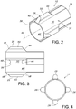
- the reconstrainment band 10 includes a hollow, generally tubular shaped band 34 having a proximal end 24 and a distal end 38.
- the band 34 has an exterior surface 40 for engaging the stent 16.
- the band 34 has an interior surface 42 for engaging the delivery tube 14.
- the exterior surface 40 has a plurality of fins 26 projecting radially outward therefrom along the longitudinal axis 44 of the band 34.
- the fins 26 are integrally connected to the band 34.
- the fins 26 each extend longitudinally in the same direction as the longitudinal axis 44.
- the band 34 includes an even number of fins 26, such that the fins are included in pairs.
- the fins 26 are desirably located relative to a transverse plane through the band 34 such that adjacent pairs of fins are separated by arcuate dimensions which are the same. For example, when two fins 26 are included, they are desirably separated by about 180°.
- the fins 26 each have an obtusely shaped surface 46 relative to the longitudinal axis 44.
- the obtusely shaped surface 46 faces the proximal end 36.
- the obtusely shaped surface 46 intersects the exterior surface 40 at a location which is longitudinally offset in the distal direction relative to the proximal end 36 of the band 34.
- the fins 26 each have an obtusely shaped surface 48 relative to the longitudinal axis 44.
- the obtusely shaped surface 48 faces the distal end 38.
- the obtusely shaped surface 48 intersects the exterior surface 40 at a location near to the distal end 38 of the band 34.
- Any number of fins 26 may be included on the band 34.
- the band 34 may include any number of fins from 1 to 10 fins.
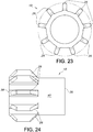
- the reconstrainment band may include nine fins 26 spaced around the exterior surface of the band 34. Desirably, each fin 26 is spaced about 40° away from each other, such that each fin is separated by an equal distance around the periphery of the band 34.
- the fins 26 each have an exterior surface 50 which extends between the obtusely shaped surfaces 46, 48.
- the exterior surface 50 faces radially outward from the band 34.
- the obtusely shaped surfaces 46, 48 most desirably form about a 45° angle with the surface 40 of the reconstrainment band 10. If desired, the fins 26 may have substantially rounded edges.
- the contour of the exterior surface 50 is preferably continuous.
- the reconstrainment band 10 and its components may be formed of expanded polytetrafluoroethylene (ePTFE) or polyurethane.
- the reconstrainment band 10 may be formed of biocompatible materials, such as biocompatible polymers including those which are known. Such polymers may include fillers such as metals, carbon fibers, glass fibers or ceramics.
- such polymers may include olefin polymers, polyethylene, polypropylene, polyvinyl chloride, polytetrafluoroethylene which is not expanded, fluorinated ethylene propylene copolymer, polyvinyl acetate, polystyrene, poly(ethylene terephthalate), naphthalene dicarboxylate derivatives, such as polyethylene naphthalate, polybutylene naphthalate, polytrimethylene naphthalate and trimethylenediol naphthalate, polyurethane, polyurea, silicone rubbers, polyamides, polycarbonates, polyaldehydes, natural rubbers, polyester copolymers, styrene-butadiene copolymers, polyethers, such as fully or partially halogenated polyethers, copolymers, and combinations thereof.
- olefin polymers polyethylene, polypropylene, polyvinyl chloride, polytetrafluoroethylene which is not expanded, fluor
- polyesters including polyethylene terephthalate (PET) polyesters, polypropylenes, polyethylenes, polyurethanes, polyolefins, polyvinyls, polymethylacetates, polyamides, naphthalane dicarboxylene derivatives, and natural silk may be included in the reconstrainment band 10.
- the reconstrainment band 10 may be formed from a polymer sleeve.
- the reconstrainment band 10 may optionally be formed of materials such as nitinol, Elgiloy, stainless steel, cobalt chromium, including MP 35N, cobalt-based alloy, tantalum, niobium, platinum, gold, titanium, combinations thereof and other biocompatible metals, polymers and materials. Additionally, the reconstrainment band 10 may include structural members which have an inner core formed of tantalum, gold, platinum, iridium, or a combination thereof, and an outer cladding of nitinol to provide composite members for improved radio-opacity or visibility. Examples of such composite members are disclosed in U.S. Patent Application Publication No. 2002/0035396 .
- the reconstrainment band 10 maybe treated with anti-thrombogenic agents (such as heparin, heparin derivatives, urokinase, and PPack (dextrophenylalanine proline arginine chloroinethylketone)), anti-proliferative agents (such as enoxaprin, angiopeptin, or monoclonal antibodies capable of blocking smooth muscle cell proliferation, hirudin, and acetylsalicylic acid), anti-inflammatory agents (such as dexamethasone, prednisolone, corticosterone, budesonide, estrogen, sulfasalazine, and mesalamine), antineoplastic/antiproliferative/anti-miotic agents (such as paclitaxel, 5-fluorouracil, cisplatin, vinblastine, vincristine, epothilones, endostatin, angiostatin and thymidine kinase inhibitors), anes
- the reconstrainment band 10 is preferably secured to the delivery tube 14 of the delivery device 12 such that the reconstrainment band is located around the delivery tube in coaxial relation therewith.
- the reconstrainment band 10 may be removably secured to the delivery tube, if desired.
- the securing of the reconstrainment band 10 to the delivery tube 14 obstructs axial displacement of the reconstrainment band relative to the delivery tube.
- the securing of the reconstrainment band 10 to the delivery tube 14 may further provide for obstruction of transverse or rotational displacement of the reconstrainment band relative to the delivery tube.
- the stent 16 may be located around the reconstrainment band 10 in coaxial relation therewith.
- the stent 16 has one or more voids in which the fins 26 extend to obstruct axial displacement of the stent 16 relative to the reconstrainment band 10. Consequently, axial displacement of the stent 16 relative to the delivery tube 14 is obstructed.
- the sheath 28 of the delivery device 12 is located around the stent 16 in coaxial relation therewith.
- the maintenance of the axial position of the stent 16 relative to the delivery tube 14 which is provided by the extension of the fins 26 into the one or more voids in the stent results in forward longitudinal displacement of the sheath 28 relative to the delivery tube enabling the sheath to cover an axial portion of the stent or the entire stent.
- the recovering of the stent 16 by the sheath 28 is referred to as reconstrainment of the stent.
- Uncovering of the outer surface of the stent 16 results in the radial expansion of the stent away from the band 34.
- the sheath 28 may be sufficiently retracted relative to the stent 16 such that the distal end 30 is located proximally relative to the proximal end 30.
- the proximal location of the distal end 30 relative to the proximal end 18 results in the radial expansion of the entire stent 16 away from the band 34.
- the sheath 28 may be retracted from a position in which the distal end 30 is located distally relative to the proximal end 18 to a position in which the distal end 30 is closer to the proximal end 18 but still located distally thereof. Consequently, an axial portion of the stent 16 is uncovered by the sheath 28 resulting in the radial expansion of the uncovered portion of the stent.
- the sheath 28 may be displaced distally relative to the delivery tube 14 such that the distal end 30 is moved closer to the distal end 20 of the stent 16. Consequently, an axial portion of the stent 16 is recovered by the sheath 28 resulting in the inward radial compression of the recovered portion of the stent.
- the recovering of the stent 16 by the sheath 28 requires the axial position of the stent 16 relative to the delivery tube 14 to be maintained during the distal or forward longitudinal displacement of the sheath 28 relative to the delivery tube.
- the axial position of the stent 16 relative to the delivery tube 14 is maintained by the extension of the fins 26 into the voids in the stent 16.
- the stent 16 may be loaded in the delivery device 12 by locating the stent around the reconstrainment band 10 in coaxial relation therewith.
- the sheath 28 may then be located around the delivery tube 14 in coaxial relation therewith such that the distal end 30 has a proximal location relative to the proximal end 18.
- the sheath 28 is then longitudinally displaced in the distal direction relative to the delivery tube 14 such that the distal end 30 engages the proximal end 18.
- the proximal end 18 Before the engagement between the proximal and distal ends 18, 30, the proximal end 18 is radially compressed in the inward direction sufficiently such that following the engagement of the distal end 30 with the proximal end 18, the interior surface 32 rides up on the exterior surface 22 such that continued distal or forward longitudinal displacement of the sheath 28 relative to the delivery tube 14 results in the inward radial compression of the axial portion of the stent 16 which is within the sheath.
- the inward radial compression of the stent 16 by the sheath 28 results in the fins 26 extending in the radial direction into the voids in the stent.
- the distal or forward longitudinal displacement of the sheath 28 relative to the delivery tube 14 is sufficient such that the distal end 30 has a longitudinal position relative to the delivery tube which coincides with the distal end 20 resulting in the entire stent 16 being located within the sheath.
- the delivery device 12 including the stent 16 located between the sheath 28 and delivery tube 14, is inserted into and through a bodily lumen and displaced therein such that the stent is positioned at a desired location within the bodily lumen.
- the stent is released from the delivery device 12 by maintaining the position of the delivery tube 14 within the bodily lumen and retracting or proximally displacing the sheath 28 relative to the delivery tube to uncover the stent.
- the sheath 28 is sufficiently retracted or rearwardly displaced relative to the delivery tube 14 such that the distal end 30 has a proximal or rearward location relative to the proximal end 18 of the stent 16.
- the entire stent 16 radially expands away from the band 34 and engages the inner surface of the bodily lumen, typically, for implantation therein.
- the axial position of the stent 16 relative to the delivery tube 14 is maintained by the engagement of the stent by the fins 26 of the reconstrainment band 10.
- the engagement between the fins 26 and the stent 16 resists the stent from being carried by the sheath 28 in the direction of the retraction thereof.
- the stent 16 is thereby deployed from the delivery device 12 into the bodily lumen.
- the delivery tube 14 and reconstrainment band 10 mounted thereon are retracted or longitudinally displaced in the distal direction relative to the stent for removal of the delivery tube and reconstrainment band from the bodily lumen.
- the radial expansion of the stent 16 may be sufficiently limited such that the radial clearance between the interior surface 24 is less than the maximum radial dimension of the fins 26. Consequently, the retraction or rearward longitudinal displacement of the reconstrainment band 10 relative to the stent 16 may result in contact between the obtusely shaped surfaces 46 and stent 16.
- the inclination of the obtusely shaped surfaces 46 reduces the likelihood of the contact between the fins 26 and stent 16 resulting in catching of the stent by the fins.
- Catching of the stent 16 by the fins 26 may impede the removal of the reconstrainment band 10 and the attached delivery tube 14 from the bodily lumen.
- catching of the stent 16 by the fins 26 may dislodge the stent from the inner surface of the bodily lumen and displace the stent relative thereto.
- the sheath 28 may be retracted or longitudinally displaced in the rearward direction relative to the delivery tube 14 such that the distal end 30 remains positioned distally relative to the proximal end 18. Consequently, retraction of the sheath 28 uncovers an axial portion of the stent 16 resulting in the radial expansion of the uncovered axial portion thereof.
- the radial expansion of the stent 16 results in the radial displacement of the sections thereof which are adjacent to the fins 26 toward the ends thereof.
- the radial displacement of the stent 16 may be sufficient such that the ends of the fins 26 are located adjacent to the interior surface 24 of the stent.
- the sheath 28 may be displaced in the distal or longitudinally forward direction relative to the delivery tube 14 such that a portion or the entire uncovered axial portion of the stent 16 is recovered by the sheath.
- the axial position of the stent relative to the reconstrainment band 10 and delivery tube 14 is maintained by the engagement of the stent by the fins 26.
- the engagement between the fins 26 and stent 16 obstructs the stent from being carried by the sheath 28 in the distal or longitudinally forward direction relative to the delivery tube 14. Reconstrainment may be required after determining that further displacement of the delivery device 12 within the body lumen is necessary to position the stent 16 at a different location within the body lumen.
- the axial portion of the stent 16 which is recovered by the sheath 28 is radially compressed in the inward direction by the sheath.
- the radial expansion of the stent 16 and longitudinal displacement of the sheath 28 may cause one or more of the fins 26 to become displaced from alignment with the voids in the stent.
- a fin 26 which is not aligned with any void in the stent 16 will normally contact the interior surface 24 as a result of the inward radial compression of the stent in the vicinity of the fin.
- the inclination of the obtusely shaped surfaces 46, 48 reduces the likelihood of contact between the fins 26 and interior surface 24 causing the stent 16 to catch on the fins 26.
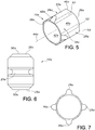
- FIG. 5 to 7 An alternative embodiment of the reconstrainment band 10a is shown in Figs. 5 to 7 .
- Parts illustrated in Figs. 5 to 7 which correspond to parts illustrated in Figs. 1 to 4 have, in Figs. 5 to 7 , the same reference numeral as in Figs. 1 to 4 with the addition of a suffix "a".
- the reconstrainment band 10a has four fins 26a.
- the fins 26a extend longitudinally in the same direction as the longitudinal axis 44a.
- the fins 26a are located relative to a transverse plane through the band 34a such that the adjacent pairs of fins are separated by arcuate dimensions which are the same.
- the obtusely shaped surfaces 46a intersect the exterior surface 40a at the proximal end 36a of the band 34a.
- the obtusely shaped surfaces 48a intersect the exterior surface 40a at the distal end 38a of the band 34a.
- the exterior surfaces 50a each have a pair of lateral regions 52 which intersect the exterior surface 40a of the band 34a on opposite sides of the corresponding fin 26a, as shown in Figs. 5 and 7 .
- the lateral regions 52 extend longitudinally in a direction which is parallel to the longitudinal axis 44a.
- the lateral regions 52 each have corresponding contours which differ from the contour of the exterior surface 40a such that the intersections between the lateral regions and exterior surface define discontinuities.
- the exterior surfaces 50a each have a shoulder region 54 which is located between the corresponding lateral regions 52, as shown in Fig. 5 .
- the shoulder regions 54 each extend longitudinally in a direction which is parallel to the longitudinal axis 44a.
- the shoulder regions 54 each have corresponding contours which differ from the contours of the lateral regions 52 such that the intersections between the shoulder and lateral regions define discontinuities.
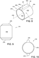
- the reconstrainment band 10b has a pair of fins 26b which project from diametrically opposed locations on the exterior surface 40b.
- the fins 26b extend longitudinally in the same direction as the longitudinal axis 44b.
- the obtusely shaped surfaces 46b intersect the exterior surface 40b at the proximal end 36b of the band 34b.
- the obtusely shaped surfaces 48b intersect the exterior surface 40b at the distal end 38b of the band 34b.
- the exterior surfaces 50b each have a pair of lateral regions 56 which intersect the exterior surface 40b of the band 34b on opposite sides of the corresponding fin 26b, as shown in Figs. 8 and 10 .
- the lateral regions 56 extend longitudinally in a direction which is parallel to the longitudinal axis 44b.
- the lateral regions 56 each have corresponding contours which differ from the contour of the exterior surface 40b such that the intersections between the lateral regions and exterior surface define discontinuities.
- the exterior surfaces 50b each have a shoulder region 58 which is located between the corresponding lateral regions 56, as shown in Fig. 8 .
- the shoulder regions 58 each extend longitudinally in a direction which is parallel to the longitudinal axis 44b.
- the shoulder regions 58 each have corresponding contours which differ from the contours of the lateral regions 56 such that the intersections between the shoulder and lateral regions define discontinuities.
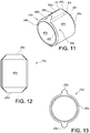
- FIG. 11 to 13 An alternative embodiment of the reconstrainment band 10c is shown in Figs. 11 to 13 . Parts illustrated in Figs. 11 to 13 which correspond to parts illustrated in Figs. 1 to 4 have, in Figs. 11 to 13 , the same reference numeral as in Figs. 1 to 4 with the addition of a suffix "c".
- the reconstrainment band 10c has a pair of fins 26c which project from diametrically opposed locations on the exterior surface 40c.
- the band 34c has a proximal intermediate end surface 60 which is circular and located between the proximal end 36c and exterior surface 40c.
- the proximal intermediate end surface 60 has a contour which is the same as the contour of the obtusely shaped surface 46c. Consequently, the intersection between the exterior surface 40c and proximal intermediate end surface 60 defines a discontinuity.
- the band 34c has a distal intermediate end surface 62 located between the distal end 38c and exterior surface 40c.
- the distal intermediate end surface 62 is circular and has a contour which is the same as the obtusely shaped surface 48c. Consequently, the intersection between the exterior surface 40c and distal intermediate end surface 64 defines a discontinuity.
- the exterior surfaces 50c each have a pair of lateral regions 64 which intersect the exterior surface 40c of the band 34c on opposite sides of the corresponding fin 26c, as shown in Figs. 11 and 13 .
- the lateral regions 64 each extend longitudinally in a direction which is parallel to the longitudinal axis 44c.
- the lateral regions 64 each have corresponding contours which differ from the contour of the exterior surface 40c such that the intersections between the lateral regions 64 and exterior surface define discontinuities.
- the exterior surfaces 50c each have a shoulder region 66 which is located between the corresponding lateral regions 64, as shown in Fig. 11 .
- the shoulder regions 66 each extend longitudinally in a direction which is parallel to the longitudinal axis 44c.
- the shoulder regions 66 each have corresponding contours which differ from the contours of the lateral regions 64 such that the intersections between the shoulder and lateral regions define discontinuities.
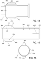
- FIG. 14 to 16 An alternative embodiment of the reconstrainment band 10d is shown in Figs. 14 to 16 . Parts illustrated in Figs. 14 to 16 which correspond to parts illustrated in Figs. 1 to 4 have, in Figs. 14 to 16 , the same reference numerals as in Figs. 1 to 4 with the addition of the suffix "d".
- the reconstrainment band 10d has a pair of fins 26d which project from diametrically opposed locations on the exterior surface 40d.
- the obtusely shaped surfaces 46d intersect the exterior surface 40d at a location which is longitudinally offset in the distal direction relative to the proximal end 36d of the band 34d.
- the obtusely shaped surfaces 48d intersect the exterior surface 40d at the distal end 38d of the band 34d.
- the exterior surfaces 50d each have a pair of base lateral regions 68 which intersect the exterior surface 40d of the band 34d on opposite sides of the corresponding fin 26d, as shown in Figs. 14 and 16 .
- the base lateral regions 68 extend longitudinally in a direction which is parallel to the longitudinal axis 44d.
- the base lateral regions 68 each have corresponding contours which differ from the contour of the exterior surface 40d such that the intersections between the base lateral regions and exterior surface define discontinuities.
- the exterior surfaces 50d each have a pair of intermediate lateral regions 70 which intersect the respective base lateral regions 68 on opposite sides of the corresponding fin 26d, as shown in Figs. 14 to 16 .
- the intermediate lateral regions 70 extend longitudinally in a direction which is parallel to the longitudinal axis 44d.
- the intermediate lateral regions 70 each have corresponding contours which differ from the contours of the base lateral regions 68 such that the intersections between the intermediate and base lateral regions define discontinuities.
- the exterior surfaces 50d each have a shoulder region 72 which is located between the corresponding intermediate lateral regions 70, as shown in Fig. 14 .
- the shoulder regions 72 each extend longitudinally in a direction which is parallel to the longitudinal axis 44d.
- the shoulder regions 72 each have corresponding contours which differ from the contours of the intermediate lateral regions 70 such that the intersections between the shoulder and intermediate lateral regions define discontinuities.
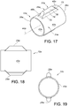
- FIG. 17 to 19 An alternative embodiment of the reconstrainment band 10e is shown in Figs. 17 to 19 . Parts illustrated in Figs. 17 to 19 which correspond to parts illustrated in Figs. 1 to 4 have, in Figs. 17 to 19 , the same reference numeral as in Figs. 1 to 4 with the addition of the suffix "e".
- the reconstrainment band 10e has a pair of fins 26e which project from diametrically opposed locations on the exterior surface 40e.
- the fins 26e have respective base obtusely shaped surfaces 73 located between the first corresponding obtusely shaped surfaces 46e and the exterior surface 40e.
- the base obtusely shaped surfaces 73 each have corresponding contours which differ from the contours of the respective first obtusely shaped surfaces 46e such that the intersections between the base obtusely shaped surfaces and respective obtusely shaped surfaces define discontinuities.
- the contours of the base obtusely shaped surfaces 73 differ from the contour of the exterior surface 40e such that the intersections between the base obtusely shaped surfaces and exterior surface define discontinuities.
- the base obtusely shaped surfaces 73 intersect the exterior surface 40e at a location which is longitudinally offset in the distal direction from the proximal end 36e of the band 34e.
- the fins 26e have respective base obtusely shaped surfaces 74 located between the corresponding second obtusely shaped surfaces 48e and the exterior surface 40e.
- the base obtusely shaped surfaces 74 each have corresponding contours which differ from the contours of the respective second obtusely shaped surfaces 48e such that the intersections between the base obtusely shaped surfaces and respective obtusely shaped surfaces define discontinuities.
- the contours of the base obtusely shaped surfaces 74 differ from the contour of the exterior surface 40e such that the intersections between the base obtusely shaped surfaces and exterior surface define discontinuities.
- the base obtusely shaped surfaces 74 intersect the exterior surface 40e at a location which is longitudinally offset in the proximal direction from the distal end 38e of the band 34e.
- the exterior surfaces 50e each have a pair of base lateral regions 75 which each intersect the exterior surface 40e of the band 34e on opposite sides of the corresponding fin 26e, as shown in Figs. 17 and 19 .
- the base lateral regions 75 extend longitudinally in a direction which is parallel to the longitudinal axis 44e.
- the base lateral regions 75 each have corresponding contours which differ from the contours of the exterior surface 40e such that the intersections between the base lateral regions and exterior surface define discontinuities.
- the exterior surfaces 50e each have a pair of intermediate lateral regions 76 which intersect the corresponding base lateral region 75 on opposite sides of the corresponding fin 26e, as shown in Figs. 17 and 19 .
- the intermediate lateral regions 76 extend longitudinally in a direction which is parallel to the longitudinal axis 44e.
- the intermediate lateral regions 76 each have corresponding contours which differ from the contours of the base lateral regions 75 such that the intersections between the intermediate and base lateral regions define discontinuities.
- the exterior surfaces 50e each have a shoulder region 78 which is located between the corresponding intermediate lateral regions 76, as shown in Fig. 17 .
- the shoulder regions 78 each extend longitudinally in a direction which is parallel to the longitudinal axis 44e.
- the shoulder regions 78 each have corresponding contours which differ from the contours of the intermediate lateral regions 76 such that the intersections between the shoulder and intermediate regions define discontinuities.
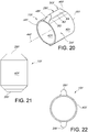
- FIG. 20 to 22 An alternative embodiment of the reconstrainment band 10f is shown in Figs. 20 to 22 . Parts illustrated in Figs. 20 to 22 which correspond to parts illustrated in Figs. 1 to 4 , have, in Figs. 20 to 22 , the same reference numeral as in Figs. 1 to 4 with the addition of the suffix "f".
- the reconstrainment band 10f has a pair of fins 26f which project from diametrically opposed locations on the exterior surface 40f.
- First obtusely shaped surfaces 46f intersect the exterior surface 40f at the proximal end 36f of the band 34f.
- Second obtusely shaped surfaces 48f intersect the exterior surface 40f at the distal end 38f of the band 34f.
- the exterior surfaces 50f each have a pair of base lateral regions 80 which each intersect the exterior surface 40f of the band 34f on opposite sides of the corresponding fin 26f, as shown in Figs. 20 and 22 .
- the base lateral regions 80 extend longitudinally in a direction which is parallel to the longitudinal axis 44f.
- the base lateral regions 80 each have corresponding contours which differ from the contour of the exterior surface 40f such that the intersections between the base lateral regions and exterior surface define discontinuities.
- the exterior surfaces 50f each have a pair of intermediate lateral regions 82 which intersect the corresponding base lateral regions 80 on opposite sides of the corresponding fin 26f, as shown in Figs. 20 and 22 .
- the intermediate lateral regions 82 extend longitudinally in a direction which is parallel to the longitudinal axis 44f.
- the intermediate lateral regions 82 each have corresponding contours which differ from the contours of the base lateral regions 80 such that the intersections between the intermediate and base lateral regions define discontinuities.
- the exterior surfaces 50f each have a shoulder region 84 which is located between the corresponding intermediate lateral regions 82, as shown in Fig. 20 .
- the shoulder region 84 each extend longitudinally in a direction which is parallel to the longitudinal axis 44f.
- the shoulder regions 84 each have corresponding contours which differ from the contours of the intermediate lateral regions 82 such that the intersections between the shoulder and intermediate lateral regions define continuities.
Landscapes
- Health & Medical Sciences (AREA)
- Engineering & Computer Science (AREA)
- Biomedical Technology (AREA)
- Heart & Thoracic Surgery (AREA)
- Oral & Maxillofacial Surgery (AREA)
- Transplantation (AREA)
- Cardiology (AREA)
- Vascular Medicine (AREA)
- Life Sciences & Earth Sciences (AREA)
- Animal Behavior & Ethology (AREA)
- General Health & Medical Sciences (AREA)
- Public Health (AREA)
- Veterinary Medicine (AREA)
- Media Introduction/Drainage Providing Device (AREA)
- Prostheses (AREA)
Description
- The present invention relates generally to reconstrainment bands and, more specifically, to a reconstrainment band having reduced interference with a stent when removed therefrom.
- An endoprosthesis or intraluminal prosthesis is a medical device used in the treatment of diseased bodily lumens. One type of endoprosthesis used in the repair and/or treatment of diseases in various body vessels is a stent. A stent is a generally longitudinal tubular device formed of biocompatible material which is useful to open and support various lumens in the body. For example, stents may be used in the vascular system, urogenital tract, esophageal tract, tracheal/bronchial tubes and bile duct, as well as in a variety of other applications in the body. These devices are implanted within the vessel to open and/or reinforce collapsing or partially occluded sections of the lumen.
Stents generally include an open flexible configuration. This configuration allows the stent to be inserted through curved vessels. Furthermore, this configuration allows the stent to be configured in a radially compressed state for intraluminal catheter implantation. Once properly positioned adjacent the damaged vessel, the stent is radially expanded so as to support and reinforce the vessel. Radial expansion of the stent may be accomplished by inflation of a balloon attached to the catheter or the stent may be of the self-expanding variety which will radially expand once deployed. Tubular shaped structures, which have been used as intraluminal vascular stents, have included helically wound coils which may have undulations or zig-zags therein, slotted stents, ring stents, braided stents and open mesh wire stents. Super-elastic materials and metallic shape memory materials have also been used to form stents. - A stent may be delivered to a specific location within a body lumen by a delivery device. The delivery device includes a delivery tube on which a reconstrainment band is supported, typically in coaxial relation therewith. A tubular stent is supported on the reconstrainment band, typically in coaxial relation therewith. A tubular sheath covers the stent in coaxial relation therewith and with the delivery tube. The reconstrainment band is fixed to the delivery tube to prevent axial displacement of the reconstrainment band relative to the delivery tube. The reconstrainment band engages the stent to prevent axial displacement of the stent relative thereto. The retention of the stent by the reconstrainment band maintains the axial position of the stent relative to the reconstrainment band and delivery tube when the sheath is axially displaced relative to the delivery tube and reconstrainment band. Without the retention of the stent provided by the reconstrainment band, axial displacement of the sheath relative to the delivery tube may cause associated axial displacement of the stent as a result of frictional contact between the sheath and stent.
- The retention of the stent by the reconstrainment band is beneficial during deployment of the stent by providing for the longitudinal position of the stent within the bodily lumen to be maintained during relative axial displacement of the sheath. The longitudinal position of the stent within the bodily lumen is typically significant. The maintenance of the longitudinal position of the stent relative to the delivery tube may be particularly difficult during reconstrainment. The sheath may be longitudinally retracted relative to the delivery tube such that a distal axial portion of the stent is exposed by the sheath and a proximal axial portion of the stent remains covered by the sheath. Reconstrainment refers to the forward axial displacement of the sheath relative to the delivery tube such that the axial distal portion of the stent which was uncovered by the longitudinal retraction of the sheath is recovered partially or completely by the sheath. The forward axial displacement of the sheath may cause forward longitudinal displacement of the stent relative to the delivery tube and, typically, the bodily lumen as a result of contact between the sheath and stent. Consequently, the stent may be carried by the sheath. Limiting or completely preventing such forward displacement of the stent relative to the delivery tube and bodily lumen is typically advantageous.
- The partial or complete uncovering of the stent which results from the retraction of the sheath relative to the delivery tube typically results in the radial expansion of the stent in an outward direction away from the reconstrainment band. Subsequently, the delivery tube and reconstrainment band mounted thereon are retracted or longitudinally displaced in the distal direction relative to the stent for removal of the delivery tube and reconstrainment band from the stent. The radial expansion of the stent may be sufficiently limited such that the radial clearance between the interior surfaces of the stent is less than the maximum radial dimension of the fins. Consequently, the retraction or rearward longitudinal displacement of the reconstrainment band relative to the stent may result in catching of the stent by the fins. Catching of the stent by the fins may impede the removal of the reconstrainment band and the attached delivery tube from within the stent. Also, catching of the stent by the fins may cause the stent to be carried by the reconstrainment band.
- Also, the reconstrainment of the stent and the initial loading thereof in the delivery device typically entails radially compressing the stent in the inward direction between the sheath and delivery tube. During the inward radial compression of the stent, it is possible for one or more of the fins to not be aligned with any of the voids in the stent into which the fins typically extend. A fin which is not aligned with any void in the stent will normally contact the interior surface of the stent as a result of the inward radial compression of the stent in the vicinity of the fin. Contact between the fin and stent may result in catching of the stent by the fin. Catching of the stent on one or more of the fins can impede the inward radial displacement of the stent toward the band and the associated inward radial compression of the stent. Consequently, the longitudinal displacement of the sheath in the distal or forward direction relative to the delivery tube which typically provides the compression of the stent is impeded. Impeding the longitudinal displacement of the sheath in the distal or forward direction relative to the
delivery tube 14 interferes with the reconstrainment of the stent, and the initial loading thereof between the sheath and reconstrainment band in the delivery device. - A stent delivery system with nested stabilizer and method of loading and using the same is known from
WO 00/71058 A1 WO 00/71058 A1 - The reconstrainment band of the present invention is used with a stent delivery device. and is defined by the wording of claims 1 or 9. The reconstrainment band includes a hollow generally tubular shaped band having proximal and distal ends and having an exterior surface for engaging a stent and an interior surface for engaging a delivery tube. The exterior surface has at least one fin projecting therefrom along the longitudinal axis of the band. The fin desirably has at least one obtusely shaped surface
relative to the longitudinal axis and facing one of the ends. The reconstrainment band is used with the delivery device for intraluminally delivering a radially distensible stent. The delivery device includes the stent, a delivery tube around which the reconstrainment band is secured, and a sheath. The stent is located between the reconstrainment band and sheath. The delivery device is used for intraluminally positioning the stent according to a method which includes positioning the delivery device within a bodily lumen, and slidably retracting the sheath from the delivery tube to uncover a portion or all of the stent. Reconstrainment of the partially uncovered stent is provided by longitudinally displacing the sheath in a forward direction relative to the delivery tube to recover a portion or the entire uncovered portion of the stent. - The fin engages the stent when the reconstrainment band is located within the stent. The engagement of the fin with the stent resists axial displacement of the stent relative to the reconstrainment band. Consequently, when the reconstrainment band is fixed to the delivery tube, axial displacement of the stent relative to the delivery tube is obstructed. The obstruction of the axial displacement of the stent retains the axial position of the stent relative to the delivery tube. The axial position of the stent is retained by the reconstrainment band when the stent is located within a sheath and the sheath is axially displaced relative to the delivery tube. Consequently, the reconstrainment band and the fixed connection thereof to the delivery tube maintain the longitudinal position of the stent within the bodily lumen during reconstrainment.
- The inclination of the obtusely shaped surface reduces the likelihood of contact between the fin and stent causing the stent to catch on the fin. Consequently, the likelihood of the catching impeding the longitudinal displacement of the reconstrainment band within the stent is reduced. As a result, removal of the reconstrainment band and the attached delivery tube from within the stent is facilitated. Also, the likelihood of the catching causing the stent to be carried by the reconstrainment band during the removal thereof from within the stent is reduced.
- Additionally, the inclination of the obtusely shaped surface reduces the likelihood of the inward radial compression and displacement of the stent toward the reconstrainment band causing the stent to catch on the fin. Consequently, the likelihood of the catching impeding the reconstrainment of the stent which typically entails the inward radial compression and displacement of the stent toward the reconstrainment band is reduced. Further, the likelihood of the catching impeding the initial loading of the stent between the sheath and reconstrainment band in the delivery device which also typically entails the inward radial compression and displacement of the stent toward the reconstrainment band is reduced.
- These and other features of the invention will be more fully understood from the following description of specific embodiments of the invention taken together with the accompanying drawings.
- In the drawings:
-
Fig. 1 is a longitudinal cross-sectional view of the reconstrainment band of the present invention showing the reconstrainment band located within a stent, the stent being shown as located within a sheath, the reconstrainment band being shown as fixed to a delivery tube located within the reconstrainment band; -
Fig. 1A is a longitudinal view of the reconstrainment band of the present invention showing the reconstrainment band located within a stent as fixed to an alternate delivery tube assembly; -
Fig. 2 is a perspective view of the reconstrainment band ofFig. 1 ; -
Fig. 3 is a longitudinal cross-sectional view of the reconstrainment band ofFig. 2 ; -
Fig. 4 is a left end elevational view of the reconstrainment band ofFig. 3 ; -
Fig. 5 is a perspective view of an alternative embodiment of the reconstrainment band ofFig. 1 ; -
Fig. 6 is a longitudinal cross-sectional view of the reconstrainment band ofFig. 5 ; -
Fig. 7 is a left end elevational view of the reconstrainment band ofFig. 6 ; -
Fig. 8 is a perspective view of a further alternative embodiment of the reconstrainment band ofFig. 1 ; -
Fig. 9 is a longitudinal cross-sectional view of the reconstrainment band ofFig. 8 ; -
Fig. 10 is a left end elevational view of the reconstrainment band ofFig. 9 ; -
Fig. 11 is a perspective view of a further alternative embodiment of the reconstrainment band ofFig. 1 ; -
Fig. 12 is a longitudinal cross-sectional view of the reconstrainment band ofFig. 11 ; -
Fig. 13 is a left end elevational view of the reconstrainment band ofFig. 12 ; -
Fig. 14 is a perspective view of a further alternative embodiment of the reconstrainment band ofFig. 1 ; -
Fig. 15 is a longitudinal cross-sectional view of the reconstrainment band ofFig. 14 ; -
Fig. 16 is a left end elevational view of the reconstrainment band ofFig. 15 ; -
Fig. 17 is a perspective view of a further alternative embodiment of the reconstrainment band ofFig. 1 ; -
Fig. 18 is a longitudinal cross-sectional view of the reconstrainment band ofFig. 17 ; -
Fig. 19 is a left end elevational view of the reconstrainment band ofFig. 17 ; -
Fig. 20 is a perspective view of a further alternative embodiment of the reconstrainment band ofFig. 1 ; -
Fig. 21 is a longitudinal cross-sectional view of the reconstrainment band ofFig. 20 ; -
Fig. 22 is a left end elevational view of the reconstrainment band ofFig. 20 ; -
Fig. 23 is a left end elevational view of an alternate embodiment of a reconstrainment band; and -
Fig. 24 is a longitudinal cross-sectional view of the reconstrainment band ofFig. 23 . - Corresponding reference characters indicate corresponding parts throughout the several views of the drawings.
- Referring to the drawings and more specifically to
Figs. 1 and 1A , thereconstrainment band 10 is used with adelivery device 12. Thedelivery device 12 includes adelivery tube 14 on which thereconstrainment band 10 is mounted in coaxial relation therewith. The mounting of thereconstrainment band 10 on thedelivery tube 14 provides for the obstruction of axial displacement of the reconstrainment band relative to the delivery tube. The mounting of thereconstrainment band 10 on thedelivery tube 14 may further provide for the obstruction of transverse or rotational displacement of the reconstrainment band relative to the delivery tube. - A
stent 16 is located around thereconstrainment band 10 in coaxial relation therewith. Thestent 16 has aproximal end 18, adistal end 20, anexterior surface 22, and aninterior surface 24. - The
stent 16 is engaged byfins 26 extending radially outward from the outer surface of thereconstrainment band 10 such that axial displacement of thestent 16 relative to the reconstrainment band is obstructed. The engagement of thestent 16 by thefins 26 may further obstruct transverse or rotational displacement of the stent relative to the reconstrainment band. - The
delivery device 12 may include atubular sheath 28 which is located circumferentially around thestent 16 in coaxially relation therewith. Thesheath 28 has adistal end 30 and aninterior surface 32. - The
delivery device 12 provides for the deployment of thestent 16 to a location within a body lumen by positioning the stent around and in engagement with thereconstrainment band 10 such that axial displacement of the stent relative to the reconstrainment band is obstructed. - The
sheath 28 is located around thestent 16 in coaxial relation therewith such that the stent is at least partially covered in the axial direction by the sheath. Thesheath 28 may completely cover thestent 16, if desired. When thestent 16 andsheath 28 are apart from one another and substantially no transverse force is applied to either, the transverse dimension of theexterior surface 22 of the stent is larger than the transverse dimension of theinterior surface 32 of the sheath. Thesheath 28 resists outward radial expansion to a greater degree relative to the resistance of thestent 16 to inward radial compression. Consequently, thestent 16 is radially compressed in the inward direction when thesheath 28 is located around the stent. - As shown in
Figs. 2 to 4 , thereconstrainment band 10 includes a hollow, generally tubular shapedband 34 having aproximal end 24 and adistal end 38. Theband 34 has anexterior surface 40 for engaging thestent 16. Theband 34 has aninterior surface 42 for engaging thedelivery tube 14. Theexterior surface 40 has a plurality offins 26 projecting radially outward therefrom along thelongitudinal axis 44 of theband 34. Thefins 26 are integrally connected to theband 34. - The
fins 26 each extend longitudinally in the same direction as thelongitudinal axis 44. Desirably, theband 34 includes an even number offins 26, such that the fins are included in pairs. Thefins 26 are desirably located relative to a transverse plane through theband 34 such that adjacent pairs of fins are separated by arcuate dimensions which are the same. For example, when twofins 26 are included, they are desirably separated by about 180°. - The
fins 26 each have an obtusely shapedsurface 46 relative to thelongitudinal axis 44. The obtusely shapedsurface 46 faces theproximal end 36. The obtusely shapedsurface 46 intersects theexterior surface 40 at a location which is longitudinally offset in the distal direction relative to theproximal end 36 of theband 34. - The
fins 26 each have an obtusely shapedsurface 48 relative to thelongitudinal axis 44. The obtusely shapedsurface 48 faces thedistal end 38. The obtusely shapedsurface 48 intersects theexterior surface 40 at a location near to thedistal end 38 of theband 34. Any number offins 26 may be included on theband 34. For example, theband 34 may include any number of fins from 1 to 10 fins. As depicted inFigs. 23-24 , for example, the reconstrainment band may include ninefins 26 spaced around the exterior surface of theband 34. Desirably, eachfin 26 is spaced about 40° away from each other, such that each fin is separated by an equal distance around the periphery of theband 34. - The
fins 26 each have anexterior surface 50 which extends between the obtusely shapedsurfaces exterior surface 50 faces radially outward from theband 34. The obtusely shapedsurfaces surface 40 of thereconstrainment band 10. If desired, thefins 26 may have substantially rounded edges. The contour of theexterior surface 50 is preferably continuous. - The
reconstrainment band 10 and its components may be formed of expanded polytetrafluoroethylene (ePTFE) or polyurethane. Thereconstrainment band 10 may be formed of biocompatible materials, such as biocompatible polymers including those which are known. Such polymers may include fillers such as metals, carbon fibers, glass fibers or ceramics. Also, such polymers may include olefin polymers, polyethylene, polypropylene, polyvinyl chloride, polytetrafluoroethylene which is not expanded, fluorinated ethylene propylene copolymer, polyvinyl acetate, polystyrene, poly(ethylene terephthalate), naphthalene dicarboxylate derivatives, such as polyethylene naphthalate, polybutylene naphthalate, polytrimethylene naphthalate and trimethylenediol naphthalate, polyurethane, polyurea, silicone rubbers, polyamides, polycarbonates, polyaldehydes, natural rubbers, polyester copolymers, styrene-butadiene copolymers, polyethers, such as fully or partially halogenated polyethers, copolymers, and combinations thereof. Also, polyesters, including polyethylene terephthalate (PET) polyesters, polypropylenes, polyethylenes, polyurethanes, polyolefins, polyvinyls, polymethylacetates, polyamides, naphthalane dicarboxylene derivatives, and natural silk may be included in thereconstrainment band 10. In alternative embodiments, thereconstrainment band 10 may be formed from a polymer sleeve. - The
reconstrainment band 10 may optionally be formed of materials such as nitinol, Elgiloy, stainless steel, cobalt chromium, including MP 35N, cobalt-based alloy, tantalum, niobium, platinum, gold, titanium, combinations thereof and other biocompatible metals, polymers and materials. Additionally, thereconstrainment band 10 may include structural members which have an inner core formed of tantalum, gold, platinum, iridium, or a combination thereof, and an outer cladding of nitinol to provide composite members for improved radio-opacity or visibility. Examples of such composite members are disclosed inU.S. Patent Application Publication No. 2002/0035396 . - The reconstrainment band 10 maybe treated with anti-thrombogenic agents (such as heparin, heparin derivatives, urokinase, and PPack (dextrophenylalanine proline arginine chloroinethylketone)), anti-proliferative agents (such as enoxaprin, angiopeptin, or monoclonal antibodies capable of blocking smooth muscle cell proliferation, hirudin, and acetylsalicylic acid), anti-inflammatory agents (such as dexamethasone, prednisolone, corticosterone, budesonide, estrogen, sulfasalazine, and mesalamine), antineoplastic/antiproliferative/anti-miotic agents (such as paclitaxel, 5-fluorouracil, cisplatin, vinblastine, vincristine, epothilones, endostatin, angiostatin and thymidine kinase inhibitors), anesthetic agents (such as lidocaine, bupivacaine, and ropivacaine), anti-coagulants (such as D-Phe-Pro-Arg chloromethyl keton, an RGD peptide-containing compound, heparin, antithrombin compounds, platelet receptor antagonists, anti-thrombin antibodies, anti-platelet receptor antibodies, aspirin, prostaglandin inhibitors, platelet inhibitors and tick antiplatelet peptides), vascular cell growth promotors (such as growth factor inhibitors, growth factor receptor antagonists, transcriptional activators, and translational promotors), vascular cell growth inhibitors (such as growth factor inhibitors, growth factor receptor antagonists, transcriptional repressors, translational repressors, replication inhibitors, inhibitory antibodies, antibodies directed against growth factors, bifunctional molecules consisting of a growth factor and a cytotoxin, bifunctional molecules consisting of an antibody and a cytotoxin), cholesterol-lowering agents, vasodilating agents, and agents which interfere with endogenous vascoactive mechanisms.
- The
reconstrainment band 10 is preferably secured to thedelivery tube 14 of thedelivery device 12 such that the reconstrainment band is located around the delivery tube in coaxial relation therewith. Thereconstrainment band 10 may be removably secured to the delivery tube, if desired. The securing of thereconstrainment band 10 to thedelivery tube 14 obstructs axial displacement of the reconstrainment band relative to the delivery tube. The securing of thereconstrainment band 10 to thedelivery tube 14 may further provide for obstruction of transverse or rotational displacement of the reconstrainment band relative to the delivery tube. - The
stent 16 may be located around thereconstrainment band 10 in coaxial relation therewith. Thestent 16 has one or more voids in which thefins 26 extend to obstruct axial displacement of thestent 16 relative to thereconstrainment band 10. Consequently, axial displacement of thestent 16 relative to thedelivery tube 14 is obstructed. Thesheath 28 of thedelivery device 12 is located around thestent 16 in coaxial relation therewith. - During longitudinal displacement of the
sheath 28 relative to thedelivery tube 14, possible longitudinal displacement of thestent 16 associated with the sheath is resisted by thefins 26 which extend into the one or more voids in the stent. Consequently, the axial position of thestent 16 relative to thedelivery tube 14 is maintained such that longitudinal retraction of thesheath 28 relative to the delivery tube may provide for the uncovering of an axial portion or the entire outer surface of the stent which was previously covered by the sheath. Also, the maintenance of the axial position of thestent 16 relative to thedelivery tube 14 which is provided by the extension of thefins 26 into the one or more voids in the stent results in forward longitudinal displacement of thesheath 28 relative to the delivery tube enabling the sheath to cover an axial portion of the stent or the entire stent. The recovering of thestent 16 by thesheath 28 is referred to as reconstrainment of the stent. - Uncovering of the outer surface of the
stent 16 results in the radial expansion of the stent away from theband 34. Thesheath 28 may be sufficiently retracted relative to thestent 16 such that thedistal end 30 is located proximally relative to theproximal end 30. The proximal location of thedistal end 30 relative to theproximal end 18 results in the radial expansion of theentire stent 16 away from theband 34. - Alternatively, the
sheath 28 may be retracted from a position in which thedistal end 30 is located distally relative to theproximal end 18 to a position in which thedistal end 30 is closer to theproximal end 18 but still located distally thereof. Consequently, an axial portion of thestent 16 is uncovered by thesheath 28 resulting in the radial expansion of the uncovered portion of the stent. Thesheath 28 may be displaced distally relative to thedelivery tube 14 such that thedistal end 30 is moved closer to thedistal end 20 of thestent 16. Consequently, an axial portion of thestent 16 is recovered by thesheath 28 resulting in the inward radial compression of the recovered portion of the stent. The recovering of thestent 16 by thesheath 28 requires the axial position of thestent 16 relative to thedelivery tube 14 to be maintained during the distal or forward longitudinal displacement of thesheath 28 relative to the delivery tube. The axial position of thestent 16 relative to thedelivery tube 14 is maintained by the extension of thefins 26 into the voids in thestent 16. - The
stent 16 may be loaded in thedelivery device 12 by locating the stent around thereconstrainment band 10 in coaxial relation therewith. Thesheath 28 may then be located around thedelivery tube 14 in coaxial relation therewith such that thedistal end 30 has a proximal location relative to theproximal end 18. Thesheath 28 is then longitudinally displaced in the distal direction relative to thedelivery tube 14 such that thedistal end 30 engages theproximal end 18. Before the engagement between the proximal and distal ends 18, 30, theproximal end 18 is radially compressed in the inward direction sufficiently such that following the engagement of thedistal end 30 with theproximal end 18, theinterior surface 32 rides up on theexterior surface 22 such that continued distal or forward longitudinal displacement of thesheath 28 relative to thedelivery tube 14 results in the inward radial compression of the axial portion of thestent 16 which is within the sheath. The inward radial compression of thestent 16 by thesheath 28 results in thefins 26 extending in the radial direction into the voids in the stent. Typically, the distal or forward longitudinal displacement of thesheath 28 relative to thedelivery tube 14 is sufficient such that thedistal end 30 has a longitudinal position relative to the delivery tube which coincides with thedistal end 20 resulting in theentire stent 16 being located within the sheath. - The
delivery device 12, including thestent 16 located between thesheath 28 anddelivery tube 14, is inserted into and through a bodily lumen and displaced therein such that the stent is positioned at a desired location within the bodily lumen. When thedelivery device 12 has positioned thestent 16 at the desired location within the body lumen, the stent is released from thedelivery device 12 by maintaining the position of thedelivery tube 14 within the bodily lumen and retracting or proximally displacing thesheath 28 relative to the delivery tube to uncover the stent. Thesheath 28 is sufficiently retracted or rearwardly displaced relative to thedelivery tube 14 such that thedistal end 30 has a proximal or rearward location relative to theproximal end 18 of thestent 16. Consequently, theentire stent 16 radially expands away from theband 34 and engages the inner surface of the bodily lumen, typically, for implantation therein. During the retraction of thesheath 28, the axial position of thestent 16 relative to thedelivery tube 14 is maintained by the engagement of the stent by thefins 26 of thereconstrainment band 10. The engagement between thefins 26 and thestent 16 resists the stent from being carried by thesheath 28 in the direction of the retraction thereof. Thestent 16 is thereby deployed from thedelivery device 12 into the bodily lumen. - Following the radial expansion of the
entire stent 16, thedelivery tube 14 andreconstrainment band 10 mounted thereon are retracted or longitudinally displaced in the distal direction relative to the stent for removal of the delivery tube and reconstrainment band from the bodily lumen. The radial expansion of thestent 16 may be sufficiently limited such that the radial clearance between theinterior surface 24 is less than the maximum radial dimension of thefins 26. Consequently, the retraction or rearward longitudinal displacement of thereconstrainment band 10 relative to thestent 16 may result in contact between the obtusely shapedsurfaces 46 andstent 16. The inclination of the obtusely shapedsurfaces 46 reduces the likelihood of the contact between thefins 26 andstent 16 resulting in catching of the stent by the fins. Catching of thestent 16 by thefins 26 may impede the removal of thereconstrainment band 10 and the attacheddelivery tube 14 from the bodily lumen. Also, catching of thestent 16 by thefins 26 may dislodge the stent from the inner surface of the bodily lumen and displace the stent relative thereto. - Following the loading of the
stent 16 in thedelivery device 12, and the insertion and displacement thereof through a bodily lumen such that the stent is positioned at the desired location in the bodily lumen, thesheath 28 may be retracted or longitudinally displaced in the rearward direction relative to thedelivery tube 14 such that thedistal end 30 remains positioned distally relative to theproximal end 18. Consequently, retraction of thesheath 28 uncovers an axial portion of thestent 16 resulting in the radial expansion of the uncovered axial portion thereof. The radial expansion of thestent 16 results in the radial displacement of the sections thereof which are adjacent to thefins 26 toward the ends thereof. The radial displacement of thestent 16 may be sufficient such that the ends of thefins 26 are located adjacent to theinterior surface 24 of the stent. Subsequently, thesheath 28 may be displaced in the distal or longitudinally forward direction relative to thedelivery tube 14 such that a portion or the entire uncovered axial portion of thestent 16 is recovered by the sheath. During the recovering of thestent 16 or reconstrainment, the axial position of the stent relative to thereconstrainment band 10 anddelivery tube 14 is maintained by the engagement of the stent by thefins 26. The engagement between thefins 26 andstent 16 obstructs the stent from being carried by thesheath 28 in the distal or longitudinally forward direction relative to thedelivery tube 14. Reconstrainment may be required after determining that further displacement of thedelivery device 12 within the body lumen is necessary to position thestent 16 at a different location within the body lumen. The axial portion of thestent 16 which is recovered by thesheath 28 is radially compressed in the inward direction by the sheath. - The radial expansion of the
stent 16 and longitudinal displacement of thesheath 28 may cause one or more of thefins 26 to become displaced from alignment with the voids in the stent. Afin 26 which is not aligned with any void in thestent 16 will normally contact theinterior surface 24 as a result of the inward radial compression of the stent in the vicinity of the fin. The inclination of the obtusely shapedsurfaces fins 26 andinterior surface 24 causing thestent 16 to catch on thefins 26. Catching of thestent 16 on one or more of thefins 26 can impede the inward radial displacement of the stent toward theband 34 and the associated inward radial compression of the stent. Consequently, the longitudinal displacement of thesheath 28 in the distal or forward direction relative to thedelivery tube 14 is impeded. Impeding the longitudinal displacement of thesheath 28 in the distal or forward direction relative to thedelivery tube 14 interferes with the reconstrainment of thestent 16, and with the initial loading thereof between the sheath andreconstrainment band 10 in thedelivery device 12. - An alternative embodiment of the
reconstrainment band 10a is shown inFigs. 5 to 7 . Parts illustrated inFigs. 5 to 7 which correspond to parts illustrated inFigs. 1 to 4 have, inFigs. 5 to 7 , the same reference numeral as inFigs. 1 to 4 with the addition of a suffix "a". In this alternative embodiment, thereconstrainment band 10a has fourfins 26a. Thefins 26a extend longitudinally in the same direction as thelongitudinal axis 44a. Thefins 26a are located relative to a transverse plane through theband 34a such that the adjacent pairs of fins are separated by arcuate dimensions which are the same. The obtusely shapedsurfaces 46a intersect theexterior surface 40a at theproximal end 36a of theband 34a. The obtusely shapedsurfaces 48a intersect theexterior surface 40a at thedistal end 38a of theband 34a. - The exterior surfaces 50a each have a pair of
lateral regions 52 which intersect theexterior surface 40a of theband 34a on opposite sides of thecorresponding fin 26a, as shown inFigs. 5 and 7 . Thelateral regions 52 extend longitudinally in a direction which is parallel to thelongitudinal axis 44a. Thelateral regions 52 each have corresponding contours which differ from the contour of theexterior surface 40a such that the intersections between the lateral regions and exterior surface define discontinuities. The exterior surfaces 50a each have ashoulder region 54 which is located between the correspondinglateral regions 52, as shown inFig. 5 . Theshoulder regions 54 each extend longitudinally in a direction which is parallel to thelongitudinal axis 44a. Theshoulder regions 54 each have corresponding contours which differ from the contours of thelateral regions 52 such that the intersections between the shoulder and lateral regions define discontinuities. - An alternative embodiment of the
reconstrainment band 10b is shown inFigs. 8 to 10 . Parts illustrated inFigs. 8 to 10 which correspond to parts illustrated inFigs. 1 to 4 have, inFigs. 8 to 10 , the same reference numeral as inFigs. 1 to 4 with the addition of the suffix "b". In this alternative embodiment, thereconstrainment band 10b has a pair offins 26b which project from diametrically opposed locations on theexterior surface 40b. Thefins 26b extend longitudinally in the same direction as thelongitudinal axis 44b. The obtusely shapedsurfaces 46b intersect theexterior surface 40b at theproximal end 36b of theband 34b. The obtusely shapedsurfaces 48b intersect theexterior surface 40b at thedistal end 38b of theband 34b. - The exterior surfaces 50b each have a pair of
lateral regions 56 which intersect theexterior surface 40b of theband 34b on opposite sides of thecorresponding fin 26b, as shown inFigs. 8 and 10 . Thelateral regions 56 extend longitudinally in a direction which is parallel to thelongitudinal axis 44b. Thelateral regions 56 each have corresponding contours which differ from the contour of theexterior surface 40b such that the intersections between the lateral regions and exterior surface define discontinuities. The exterior surfaces 50b each have ashoulder region 58 which is located between the correspondinglateral regions 56, as shown inFig. 8 . Theshoulder regions 58 each extend longitudinally in a direction which is parallel to thelongitudinal axis 44b. Theshoulder regions 58 each have corresponding contours which differ from the contours of thelateral regions 56 such that the intersections between the shoulder and lateral regions define discontinuities. - An alternative embodiment of the
reconstrainment band 10c is shown inFigs. 11 to 13 . Parts illustrated inFigs. 11 to 13 which correspond to parts illustrated inFigs. 1 to 4 have, inFigs. 11 to 13 , the same reference numeral as inFigs. 1 to 4 with the addition of a suffix "c". In this alternative embodiment, thereconstrainment band 10c has a pair offins 26c which project from diametrically opposed locations on theexterior surface 40c. Theband 34c has a proximalintermediate end surface 60 which is circular and located between theproximal end 36c andexterior surface 40c. The proximalintermediate end surface 60 has a contour which is the same as the contour of the obtusely shapedsurface 46c. Consequently, the intersection between theexterior surface 40c and proximalintermediate end surface 60 defines a discontinuity. - The
band 34c has a distalintermediate end surface 62 located between thedistal end 38c andexterior surface 40c. The distalintermediate end surface 62 is circular and has a contour which is the same as the obtusely shapedsurface 48c. Consequently, the intersection between theexterior surface 40c and distalintermediate end surface 64 defines a discontinuity. - The exterior surfaces 50c each have a pair of
lateral regions 64 which intersect theexterior surface 40c of theband 34c on opposite sides of thecorresponding fin 26c, as shown inFigs. 11 and 13 . Thelateral regions 64 each extend longitudinally in a direction which is parallel to the longitudinal axis 44c. Thelateral regions 64 each have corresponding contours which differ from the contour of theexterior surface 40c such that the intersections between thelateral regions 64 and exterior surface define discontinuities. The exterior surfaces 50c each have a shoulder region 66 which is located between the correspondinglateral regions 64, as shown inFig. 11 . The shoulder regions 66 each extend longitudinally in a direction which is parallel to the longitudinal axis 44c. The shoulder regions 66 each have corresponding contours which differ from the contours of thelateral regions 64 such that the intersections between the shoulder and lateral regions define discontinuities. - An alternative embodiment of the
reconstrainment band 10d is shown inFigs. 14 to 16 . Parts illustrated inFigs. 14 to 16 which correspond to parts illustrated inFigs. 1 to 4 have, inFigs. 14 to 16 , the same reference numerals as inFigs. 1 to 4 with the addition of the suffix "d". In this alternative embodiment, thereconstrainment band 10d has a pair offins 26d which project from diametrically opposed locations on theexterior surface 40d. The obtusely shapedsurfaces 46d intersect theexterior surface 40d at a location which is longitudinally offset in the distal direction relative to theproximal end 36d of theband 34d. The obtusely shapedsurfaces 48d intersect theexterior surface 40d at thedistal end 38d of theband 34d. - The exterior surfaces 50d each have a pair of base
lateral regions 68 which intersect theexterior surface 40d of theband 34d on opposite sides of thecorresponding fin 26d, as shown inFigs. 14 and 16 . The baselateral regions 68 extend longitudinally in a direction which is parallel to thelongitudinal axis 44d. The baselateral regions 68 each have corresponding contours which differ from the contour of theexterior surface 40d such that the intersections between the base lateral regions and exterior surface define discontinuities. - The exterior surfaces 50d each have a pair of intermediate
lateral regions 70 which intersect the respective baselateral regions 68 on opposite sides of thecorresponding fin 26d, as shown inFigs. 14 to 16 . The intermediatelateral regions 70 extend longitudinally in a direction which is parallel to thelongitudinal axis 44d. The intermediatelateral regions 70 each have corresponding contours which differ from the contours of the baselateral regions 68 such that the intersections between the intermediate and base lateral regions define discontinuities. The exterior surfaces 50d each have ashoulder region 72 which is located between the corresponding intermediatelateral regions 70, as shown inFig. 14 . Theshoulder regions 72 each extend longitudinally in a direction which is parallel to thelongitudinal axis 44d. Theshoulder regions 72 each have corresponding contours which differ from the contours of the intermediatelateral regions 70 such that the intersections between the shoulder and intermediate lateral regions define discontinuities. - An alternative embodiment of the
reconstrainment band 10e is shown inFigs. 17 to 19 . Parts illustrated inFigs. 17 to 19 which correspond to parts illustrated inFigs. 1 to 4 have, inFigs. 17 to 19 , the same reference numeral as inFigs. 1 to 4 with the addition of the suffix "e". In this alternative embodiment, thereconstrainment band 10e has a pair offins 26e which project from diametrically opposed locations on theexterior surface 40e. - The
fins 26e have respective base obtusely shapedsurfaces 73 located between the first corresponding obtusely shapedsurfaces 46e and theexterior surface 40e. The base obtusely shapedsurfaces 73 each have corresponding contours which differ from the contours of the respective first obtusely shapedsurfaces 46e such that the intersections between the base obtusely shaped surfaces and respective obtusely shaped surfaces define discontinuities. The contours of the base obtusely shapedsurfaces 73 differ from the contour of theexterior surface 40e such that the intersections between the base obtusely shaped surfaces and exterior surface define discontinuities. The base obtusely shapedsurfaces 73 intersect theexterior surface 40e at a location which is longitudinally offset in the distal direction from theproximal end 36e of theband 34e. - The
fins 26e have respective base obtusely shaped surfaces 74 located between the corresponding second obtusely shapedsurfaces 48e and theexterior surface 40e. The base obtusely shaped surfaces 74 each have corresponding contours which differ from the contours of the respective second obtusely shapedsurfaces 48e such that the intersections between the base obtusely shaped surfaces and respective obtusely shaped surfaces define discontinuities. The contours of the base obtusely shaped surfaces 74 differ from the contour of theexterior surface 40e such that the intersections between the base obtusely shaped surfaces and exterior surface define discontinuities. The base obtusely shaped surfaces 74 intersect theexterior surface 40e at a location which is longitudinally offset in the proximal direction from thedistal end 38e of theband 34e. - The exterior surfaces 50e each have a pair of base
lateral regions 75 which each intersect theexterior surface 40e of theband 34e on opposite sides of thecorresponding fin 26e, as shown inFigs. 17 and 19 . The baselateral regions 75 extend longitudinally in a direction which is parallel to thelongitudinal axis 44e. The baselateral regions 75 each have corresponding contours which differ from the contours of theexterior surface 40e such that the intersections between the base lateral regions and exterior surface define discontinuities. - The exterior surfaces 50e each have a pair of intermediate
lateral regions 76 which intersect the correspondingbase lateral region 75 on opposite sides of thecorresponding fin 26e, as shown inFigs. 17 and 19 . The intermediatelateral regions 76 extend longitudinally in a direction which is parallel to thelongitudinal axis 44e. The intermediatelateral regions 76 each have corresponding contours which differ from the contours of the baselateral regions 75 such that the intersections between the intermediate and base lateral regions define discontinuities. - The exterior surfaces 50e each have a
shoulder region 78 which is located between the corresponding intermediatelateral regions 76, as shown inFig. 17 . Theshoulder regions 78 each extend longitudinally in a direction which is parallel to thelongitudinal axis 44e. Theshoulder regions 78 each have corresponding contours which differ from the contours of the intermediatelateral regions 76 such that the intersections between the shoulder and intermediate regions define discontinuities. - An alternative embodiment of the
reconstrainment band 10f is shown inFigs. 20 to 22 . Parts illustrated inFigs. 20 to 22 which correspond to parts illustrated inFigs. 1 to 4 , have, inFigs. 20 to 22 , the same reference numeral as inFigs. 1 to 4 with the addition of the suffix "f". In this alternative embodiment, thereconstrainment band 10f has a pair offins 26f which project from diametrically opposed locations on theexterior surface 40f. First obtusely shapedsurfaces 46f intersect theexterior surface 40f at theproximal end 36f of theband 34f. Second obtusely shapedsurfaces 48f intersect theexterior surface 40f at thedistal end 38f of theband 34f. - The
exterior surfaces 50f each have a pair of baselateral regions 80 which each intersect theexterior surface 40f of theband 34f on opposite sides of thecorresponding fin 26f, as shown inFigs. 20 and 22 . The baselateral regions 80 extend longitudinally in a direction which is parallel to thelongitudinal axis 44f. The baselateral regions 80 each have corresponding contours which differ from the contour of theexterior surface 40f such that the intersections between the base lateral regions and exterior surface define discontinuities.
Theexterior surfaces 50f each have a pair of intermediatelateral regions 82 which intersect the correspondingbase lateral regions 80 on opposite sides of thecorresponding fin 26f, as shown inFigs. 20 and 22 . The intermediatelateral regions 82 extend longitudinally in a direction which is parallel to thelongitudinal axis 44f. The intermediatelateral regions 82 each have corresponding contours which differ from the contours of the baselateral regions 80 such that the intersections between the intermediate and base lateral regions define discontinuities.
Theexterior surfaces 50f each have ashoulder region 84 which is located between the corresponding intermediatelateral regions 82, as shown inFig. 20 . Theshoulder region 84 each extend longitudinally in a direction which is parallel to thelongitudinal axis 44f. Theshoulder regions 84 each have corresponding contours which differ from the contours of the intermediatelateral regions 82 such that the intersections between the shoulder and intermediate lateral regions define continuities.
U.S. Patent Nos. 5,833,632 ,6,014,919 ,6,260,458 , and6,428,489 ,6,431,039 are hereby cited. Applicant's co-pendingU.S. Patent Publication No. 2008/0009934 is hereby cited. While the invention has been described by reference to certain preferred embodiments, it should be understood that numerous changes could be made within the scope of the inventive concept described. Accordingly, it is intended that the invention not be limited to the disclosed embodiments, but that it have the full scope permitted by the language of the following claims.
Claims (9)
- A reconstrainment band (10) for use with a stent delivery device (12), said reconstrainment band (10) comprising:a hollow generally tubular shaped band (34) having proximal and distal ends (24, 38) and having an exterior surface (40) for engaging a stent (16) and an interior surface (42) for engaging a delivery tube (14),said exterior surface (40) having at least one fin projecting therefrom along a longitudinal axis (44) of said band (10), characterized in that, said at least one fin comprises:a proximal obtusely shaped surface (46) being obtusely oriented relative to the longitudinal axis (44) and facing the proximal end (36), anda distal obtusely shaped surface (48) being obtusely oriented relative to the longitudinal axis (44) and facing the distal end (38).
- A reconstrainment band (10) according to claim 1, wherein said fin (26) is coupled to said band (34).
- A reconstrainment band (10) according to claim 1, wherein said fin (26) is integral to said band (34).
- A reconstrainment band (10) according to claim 1, wherein said fin (26) comprises a plurality of fins (26).
- A reconstrainment band (10) according to claim 4, wherein said plurality of fins (26) comprises two opposed fins (26).
- A reconstrainment band (10) according to claim 5, wherein a first fin (26) and a second fin (26) of said two fins (26) are circumferentially disposed at about 180°.
- A reconstrainment band (10) according to claim 1, wherein said band (34) comprises a material selected from the group consisting of: a metal, a stainless steel, a polymer, and combinations thereof.
- A reconstrainment band (10) according to claim 1, wherein said fin (26) extends longitudinally outward from said band (34).
- A delivery device (12) for intraluminally delivering a radially distensible stent (16) comprising:a delivery tube (14);a reconstrainment band (10) having a hollow generally tubular shaped band (34) having proximal and distal ends (36, 38) and having an exterior surface (40) and interior surface (42), the interior surface (42) engaging the delivery tube (14) such that the band (34) is secured thereto,a radially distensible generally tubular shaped stent (16) located around the band (34) such that the fin (26) extends into a void in the stent (16); anda hollow generally tubular sheath (28) located around the stent (16) in coaxial relation therewith, the sheath (28) being longitudinally displaceable relative to the stent (16) and delivery tube (14),the exterior surface (40) having at least one fin (26) projecting therefrom along the longitudinal axis (44) of the band (34), characterized in that the fin (26) has a proximal obtusely shaped surface (46), said proximal obtusely shaped surface (46) being obtusely oriented relative to the longitudinal axis (44) and facing the proximal end (36), and a distal obtusely shaped surface (48) being obtusely oriented relative to the longitudinal axis (44) and facing the distal end (38).
Applications Claiming Priority (2)
| Application Number | Priority Date | Filing Date | Title |
|---|---|---|---|
| US22997609P | 2009-07-30 | 2009-07-30 | |
| PCT/US2010/043521 WO2011014550A1 (en) | 2009-07-30 | 2010-07-28 | Reconstrainment band with reduced removal interference |
Publications (2)
| Publication Number | Publication Date |
|---|---|
| EP2459128A1 EP2459128A1 (en) | 2012-06-06 |
| EP2459128B1 true EP2459128B1 (en) | 2018-04-04 |
Family
ID=42674657
Family Applications (1)
| Application Number | Title | Priority Date | Filing Date |
|---|---|---|---|
| EP10742353.5A Active EP2459128B1 (en) | 2009-07-30 | 2010-07-28 | Reconstrainment band with reduced removal interference |
Country Status (6)
| Country | Link |
|---|---|
| US (5) | US20110029065A1 (en) |
| EP (1) | EP2459128B1 (en) |
| JP (1) | JP5716025B2 (en) |
| AU (1) | AU2010279034B2 (en) |
| CA (1) | CA2764453C (en) |
| WO (1) | WO2011014550A1 (en) |
Families Citing this family (31)
| Publication number | Priority date | Publication date | Assignee | Title |
|---|---|---|---|---|
| US6866679B2 (en) | 2002-03-12 | 2005-03-15 | Ev3 Inc. | Everting stent and stent delivery system |
| US20110029065A1 (en) | 2009-07-30 | 2011-02-03 | Boston Scientific Scimed, Inc | Reconstrainment Band with Reduced Removal Interference |
| US10130470B2 (en) | 2010-08-17 | 2018-11-20 | St. Jude Medical, Llc | Sleeve for facilitating movement of a transfemoral catheter |
| US9439795B2 (en) | 2010-09-17 | 2016-09-13 | St. Jude Medical, Cardiology Division, Inc. | Retainers for transcatheter heart valve delivery systems |
| US9370422B2 (en) | 2011-07-28 | 2016-06-21 | St. Jude Medical, Inc. | Expandable radiopaque marker for transcatheter aortic valve implantation |
| US9072624B2 (en) | 2012-02-23 | 2015-07-07 | Covidien Lp | Luminal stenting |
| US20130226278A1 (en) | 2012-02-23 | 2013-08-29 | Tyco Healthcare Group Lp | Methods and apparatus for luminal stenting |
| US9078659B2 (en) | 2012-04-23 | 2015-07-14 | Covidien Lp | Delivery system with hooks for resheathability |
| US9480561B2 (en) | 2012-06-26 | 2016-11-01 | St. Jude Medical, Cardiology Division, Inc. | Apparatus and method for aortic protection and TAVI planar alignment |
| US9918837B2 (en) | 2012-06-29 | 2018-03-20 | St. Jude Medical, Cardiology Division, Inc. | System to assist in the release of a collapsible stent from a delivery device |
| US9724222B2 (en) | 2012-07-20 | 2017-08-08 | Covidien Lp | Resheathable stent delivery system |
| US10857274B2 (en) | 2012-11-06 | 2020-12-08 | Queen Mary University Of London | Mechanical circulatory support device with centrifugal impeller designed for implantation in the descending aorta |
| CA2905499C (en) * | 2013-03-15 | 2018-06-26 | West Virginia University Research Corporation | Process for pure carbon production, compositions, and methods thereof |
| US10130500B2 (en) | 2013-07-25 | 2018-11-20 | Covidien Lp | Methods and apparatus for luminal stenting |
| US9474639B2 (en) | 2013-08-27 | 2016-10-25 | Covidien Lp | Delivery of medical devices |
| US9782186B2 (en) | 2013-08-27 | 2017-10-10 | Covidien Lp | Vascular intervention system |
| EP3043755B1 (en) | 2013-09-12 | 2022-10-19 | St. Jude Medical, Cardiology Division, Inc. | Atraumatic interface in an implant delivery device |
| EP3454794B1 (en) | 2016-05-13 | 2021-04-14 | St. Jude Medical, Cardiology Division, Inc. | Systems for device implantation |
| US11524153B2 (en) | 2016-10-03 | 2022-12-13 | Queen Mary University Of London | Mechanical circulatory support device with axial flow turbomachine optimized for heart failure and cardio-renal syndrome by implantation in the descending aorta |
| US12090310B2 (en) | 2016-10-03 | 2024-09-17 | Procardia Llc | Mechanical circulatory support device with axial flow turbomachine optimized for heart failure and cardio-renal syndrome by implantation in the descending aorta |
| US10376396B2 (en) * | 2017-01-19 | 2019-08-13 | Covidien Lp | Coupling units for medical device delivery systems |
| US11116959B2 (en) | 2018-04-04 | 2021-09-14 | Theodosios Alexander | Removable mechanical circulatory support for short term use |
| US11071637B2 (en) | 2018-04-12 | 2021-07-27 | Covidien Lp | Medical device delivery |
| US11123209B2 (en) | 2018-04-12 | 2021-09-21 | Covidien Lp | Medical device delivery |
| US10786377B2 (en) | 2018-04-12 | 2020-09-29 | Covidien Lp | Medical device delivery |
| US11413176B2 (en) | 2018-04-12 | 2022-08-16 | Covidien Lp | Medical device delivery |
| US11413174B2 (en) | 2019-06-26 | 2022-08-16 | Covidien Lp | Core assembly for medical device delivery systems |
| CN114828942A (en) | 2019-06-28 | 2022-07-29 | 狄奥多西·亚历山大 | Removable mechanical circulation support device for short-term use |
| US12029670B2 (en) | 2020-12-23 | 2024-07-09 | Olympus Corporation | Stent delivery device |
| US12042413B2 (en) | 2021-04-07 | 2024-07-23 | Covidien Lp | Delivery of medical devices |
| US11944558B2 (en) | 2021-08-05 | 2024-04-02 | Covidien Lp | Medical device delivery devices, systems, and methods |
Family Cites Families (13)
| Publication number | Priority date | Publication date | Assignee | Title |
|---|---|---|---|---|
| US7101392B2 (en) | 1992-03-31 | 2006-09-05 | Boston Scientific Corporation | Tubular medical endoprostheses |
| US6428489B1 (en) | 1995-12-07 | 2002-08-06 | Precision Vascular Systems, Inc. | Guidewire system |
| US5833632A (en) | 1995-12-07 | 1998-11-10 | Sarcos, Inc. | Hollow guide wire apparatus catheters |
| US6077295A (en) * | 1996-07-15 | 2000-06-20 | Advanced Cardiovascular Systems, Inc. | Self-expanding stent delivery system |
| US6014919A (en) | 1996-09-16 | 2000-01-18 | Precision Vascular Systems, Inc. | Method and apparatus for forming cuts in catheters, guidewires, and the like |
| US6258099B1 (en) * | 1999-03-31 | 2001-07-10 | Scimed Life Systems, Inc. | Stent security balloon/balloon catheter |
| JP4299973B2 (en) * | 1999-05-20 | 2009-07-22 | ボストン サイエンティフィック リミテッド | Stent delivery system with a shrink stabilizer |
| WO2002007795A2 (en) * | 2000-07-24 | 2002-01-31 | Jeffrey Grayzel | Stiffened balloon catheter for dilatation and stenting |
| US7473271B2 (en) * | 2003-04-11 | 2009-01-06 | Boston Scientific Scimed, Inc. | Stent delivery system with securement and deployment accuracy |
| AU2005280151A1 (en) * | 2004-08-26 | 2006-03-09 | Cook Incorporated | Delivery system with controlled frictional properties |
| US8337543B2 (en) * | 2004-11-05 | 2012-12-25 | Boston Scientific Scimed, Inc. | Prosthesis anchoring and deploying device |
| CN101495069A (en) | 2006-07-07 | 2009-07-29 | 波士顿科学有限公司 | Endoprosthesis delivery system with stent holder |
| US20110029065A1 (en) * | 2009-07-30 | 2011-02-03 | Boston Scientific Scimed, Inc | Reconstrainment Band with Reduced Removal Interference |
-
2010
- 2010-07-28 US US12/845,243 patent/US20110029065A1/en not_active Abandoned
- 2010-07-28 EP EP10742353.5A patent/EP2459128B1/en active Active
- 2010-07-28 AU AU2010279034A patent/AU2010279034B2/en not_active Ceased
- 2010-07-28 WO PCT/US2010/043521 patent/WO2011014550A1/en active Application Filing
- 2010-07-28 JP JP2012522996A patent/JP5716025B2/en active Active
- 2010-07-28 CA CA2764453A patent/CA2764453C/en not_active Expired - Fee Related
-
2016
- 2016-01-28 US US15/009,449 patent/US10265208B2/en active Active
-
2019
- 2019-03-21 US US16/360,826 patent/US11065141B2/en active Active
-
2021
- 2021-06-30 US US17/364,140 patent/US11931278B2/en active Active
-
2024
- 2024-02-23 US US18/585,858 patent/US20240197511A1/en active Pending
Also Published As
| Publication number | Publication date |
|---|---|
| US20110029065A1 (en) | 2011-02-03 |
| US20160143761A1 (en) | 2016-05-26 |
| AU2010279034A1 (en) | 2012-02-09 |
| JP5716025B2 (en) | 2015-05-13 |
| US10265208B2 (en) | 2019-04-23 |
| AU2010279034B2 (en) | 2014-09-18 |
| US11065141B2 (en) | 2021-07-20 |
| CA2764453A1 (en) | 2011-02-03 |
| US20240197511A1 (en) | 2024-06-20 |
| JP2013500777A (en) | 2013-01-10 |
| WO2011014550A1 (en) | 2011-02-03 |
| CA2764453C (en) | 2017-06-27 |
| US20210322194A1 (en) | 2021-10-21 |
| US20190216626A1 (en) | 2019-07-18 |
| EP2459128A1 (en) | 2012-06-06 |
| US11931278B2 (en) | 2024-03-19 |
Similar Documents
| Publication | Publication Date | Title |
|---|---|---|
| US11931278B2 (en) | Reconstrainment band with reduced removal interference | |
| US11786386B2 (en) | Integrated stent repositioning and retrieval loop | |
| US11583421B2 (en) | Stent retrieval system | |
| AU2003259932C1 (en) | Endoprosthesis deployment system for treating vascular bifurcations | |
| JP5142239B2 (en) | Endoprosthesis deployment system for treating vascular bifurcations | |
| EP2023867B1 (en) | Stent delivery assembly and method for loading a stent using a suture retaining mechanism |
Legal Events
| Date | Code | Title | Description |
|---|---|---|---|
| PUAI | Public reference made under article 153(3) epc to a published international application that has entered the european phase |
Free format text: ORIGINAL CODE: 0009012 |
|
| 17P | Request for examination filed |
Effective date: 20120125 |
|
| AK | Designated contracting states |
Kind code of ref document: A1 Designated state(s): AL AT BE BG CH CY CZ DE DK EE ES FI FR GB GR HR HU IE IS IT LI LT LU LV MC MK MT NL NO PL PT RO SE SI SK SM TR |
|
| DAX | Request for extension of the european patent (deleted) | ||
| 17Q | First examination report despatched |
Effective date: 20150407 |
|
| REG | Reference to a national code |
Ref country code: DE Ref legal event code: R079 Ref document number: 602010049665 Country of ref document: DE Free format text: PREVIOUS MAIN CLASS: A61F0002840000 Ipc: A61F0002950000 |
|
| GRAP | Despatch of communication of intention to grant a patent |
Free format text: ORIGINAL CODE: EPIDOSNIGR1 |
|
| RIC1 | Information provided on ipc code assigned before grant |
Ipc: A61F 2/95 20130101AFI20171009BHEP |
|
| INTG | Intention to grant announced |
Effective date: 20171026 |
|
| GRAS | Grant fee paid |
Free format text: ORIGINAL CODE: EPIDOSNIGR3 |
|
| GRAA | (expected) grant |
Free format text: ORIGINAL CODE: 0009210 |
|
| AK | Designated contracting states |
Kind code of ref document: B1 Designated state(s): AL AT BE BG CH CY CZ DE DK EE ES FI FR GB GR HR HU IE IS IT LI LT LU LV MC MK MT NL NO PL PT RO SE SI SK SM TR |
|
| REG | Reference to a national code |
Ref country code: GB Ref legal event code: FG4D |
|
| REG | Reference to a national code |
Ref country code: CH Ref legal event code: EP |
|
| REG | Reference to a national code |
Ref country code: AT Ref legal event code: REF Ref document number: 984755 Country of ref document: AT Kind code of ref document: T Effective date: 20180415 |
|
| REG | Reference to a national code |
Ref country code: IE Ref legal event code: FG4D |
|
| REG | Reference to a national code |
Ref country code: DE Ref legal event code: R096 Ref document number: 602010049665 Country of ref document: DE |
|
| REG | Reference to a national code |
Ref country code: NL Ref legal event code: FP |
|
| REG | Reference to a national code |
Ref country code: FR Ref legal event code: PLFP Year of fee payment: 9 |
|
| REG | Reference to a national code |
Ref country code: LT Ref legal event code: MG4D |
|
| PGFP | Annual fee paid to national office [announced via postgrant information from national office to epo] |
Ref country code: FR Payment date: 20180612 Year of fee payment: 9 |
|
| PG25 | Lapsed in a contracting state [announced via postgrant information from national office to epo] |
Ref country code: LT Free format text: LAPSE BECAUSE OF FAILURE TO SUBMIT A TRANSLATION OF THE DESCRIPTION OR TO PAY THE FEE WITHIN THE PRESCRIBED TIME-LIMIT Effective date: 20180404 Ref country code: PL Free format text: LAPSE BECAUSE OF FAILURE TO SUBMIT A TRANSLATION OF THE DESCRIPTION OR TO PAY THE FEE WITHIN THE PRESCRIBED TIME-LIMIT Effective date: 20180404 Ref country code: BG Free format text: LAPSE BECAUSE OF FAILURE TO SUBMIT A TRANSLATION OF THE DESCRIPTION OR TO PAY THE FEE WITHIN THE PRESCRIBED TIME-LIMIT Effective date: 20180704 Ref country code: FI Free format text: LAPSE BECAUSE OF FAILURE TO SUBMIT A TRANSLATION OF THE DESCRIPTION OR TO PAY THE FEE WITHIN THE PRESCRIBED TIME-LIMIT Effective date: 20180404 Ref country code: AL Free format text: LAPSE BECAUSE OF FAILURE TO SUBMIT A TRANSLATION OF THE DESCRIPTION OR TO PAY THE FEE WITHIN THE PRESCRIBED TIME-LIMIT Effective date: 20180404 Ref country code: SE Free format text: LAPSE BECAUSE OF FAILURE TO SUBMIT A TRANSLATION OF THE DESCRIPTION OR TO PAY THE FEE WITHIN THE PRESCRIBED TIME-LIMIT Effective date: 20180404 Ref country code: NO Free format text: LAPSE BECAUSE OF FAILURE TO SUBMIT A TRANSLATION OF THE DESCRIPTION OR TO PAY THE FEE WITHIN THE PRESCRIBED TIME-LIMIT Effective date: 20180704 Ref country code: ES Free format text: LAPSE BECAUSE OF FAILURE TO SUBMIT A TRANSLATION OF THE DESCRIPTION OR TO PAY THE FEE WITHIN THE PRESCRIBED TIME-LIMIT Effective date: 20180404 |
|
| PGFP | Annual fee paid to national office [announced via postgrant information from national office to epo] |
Ref country code: NL Payment date: 20180712 Year of fee payment: 9 |
|
| PG25 | Lapsed in a contracting state [announced via postgrant information from national office to epo] |
Ref country code: GR Free format text: LAPSE BECAUSE OF FAILURE TO SUBMIT A TRANSLATION OF THE DESCRIPTION OR TO PAY THE FEE WITHIN THE PRESCRIBED TIME-LIMIT Effective date: 20180705 Ref country code: HR Free format text: LAPSE BECAUSE OF FAILURE TO SUBMIT A TRANSLATION OF THE DESCRIPTION OR TO PAY THE FEE WITHIN THE PRESCRIBED TIME-LIMIT Effective date: 20180404 Ref country code: LV Free format text: LAPSE BECAUSE OF FAILURE TO SUBMIT A TRANSLATION OF THE DESCRIPTION OR TO PAY THE FEE WITHIN THE PRESCRIBED TIME-LIMIT Effective date: 20180404 |
|
| REG | Reference to a national code |
Ref country code: AT Ref legal event code: MK05 Ref document number: 984755 Country of ref document: AT Kind code of ref document: T Effective date: 20180404 |
|
| PG25 | Lapsed in a contracting state [announced via postgrant information from national office to epo] |
Ref country code: PT Free format text: LAPSE BECAUSE OF FAILURE TO SUBMIT A TRANSLATION OF THE DESCRIPTION OR TO PAY THE FEE WITHIN THE PRESCRIBED TIME-LIMIT Effective date: 20180806 |
|
| REG | Reference to a national code |
Ref country code: DE Ref legal event code: R097 Ref document number: 602010049665 Country of ref document: DE |
|
| PG25 | Lapsed in a contracting state [announced via postgrant information from national office to epo] |
Ref country code: EE Free format text: LAPSE BECAUSE OF FAILURE TO SUBMIT A TRANSLATION OF THE DESCRIPTION OR TO PAY THE FEE WITHIN THE PRESCRIBED TIME-LIMIT Effective date: 20180404 Ref country code: DK Free format text: LAPSE BECAUSE OF FAILURE TO SUBMIT A TRANSLATION OF THE DESCRIPTION OR TO PAY THE FEE WITHIN THE PRESCRIBED TIME-LIMIT Effective date: 20180404 Ref country code: AT Free format text: LAPSE BECAUSE OF FAILURE TO SUBMIT A TRANSLATION OF THE DESCRIPTION OR TO PAY THE FEE WITHIN THE PRESCRIBED TIME-LIMIT Effective date: 20180404 Ref country code: SK Free format text: LAPSE BECAUSE OF FAILURE TO SUBMIT A TRANSLATION OF THE DESCRIPTION OR TO PAY THE FEE WITHIN THE PRESCRIBED TIME-LIMIT Effective date: 20180404 Ref country code: CZ Free format text: LAPSE BECAUSE OF FAILURE TO SUBMIT A TRANSLATION OF THE DESCRIPTION OR TO PAY THE FEE WITHIN THE PRESCRIBED TIME-LIMIT Effective date: 20180404 Ref country code: RO Free format text: LAPSE BECAUSE OF FAILURE TO SUBMIT A TRANSLATION OF THE DESCRIPTION OR TO PAY THE FEE WITHIN THE PRESCRIBED TIME-LIMIT Effective date: 20180404 |
|
| PLBE | No opposition filed within time limit |
Free format text: ORIGINAL CODE: 0009261 |
|
| STAA | Information on the status of an ep patent application or granted ep patent |
Free format text: STATUS: NO OPPOSITION FILED WITHIN TIME LIMIT |
|
| PG25 | Lapsed in a contracting state [announced via postgrant information from national office to epo] |
Ref country code: IT Free format text: LAPSE BECAUSE OF FAILURE TO SUBMIT A TRANSLATION OF THE DESCRIPTION OR TO PAY THE FEE WITHIN THE PRESCRIBED TIME-LIMIT Effective date: 20180404 Ref country code: SM Free format text: LAPSE BECAUSE OF FAILURE TO SUBMIT A TRANSLATION OF THE DESCRIPTION OR TO PAY THE FEE WITHIN THE PRESCRIBED TIME-LIMIT Effective date: 20180404 |
|
| REG | Reference to a national code |
Ref country code: CH Ref legal event code: PL |
|
| 26N | No opposition filed |
Effective date: 20190107 |
|
| PG25 | Lapsed in a contracting state [announced via postgrant information from national office to epo] |
Ref country code: MC Free format text: LAPSE BECAUSE OF FAILURE TO SUBMIT A TRANSLATION OF THE DESCRIPTION OR TO PAY THE FEE WITHIN THE PRESCRIBED TIME-LIMIT Effective date: 20180404 Ref country code: LU Free format text: LAPSE BECAUSE OF NON-PAYMENT OF DUE FEES Effective date: 20180728 |
|
| REG | Reference to a national code |
Ref country code: BE Ref legal event code: MM Effective date: 20180731 |
|
| PG25 | Lapsed in a contracting state [announced via postgrant information from national office to epo] |
Ref country code: CH Free format text: LAPSE BECAUSE OF NON-PAYMENT OF DUE FEES Effective date: 20180731 Ref country code: LI Free format text: LAPSE BECAUSE OF NON-PAYMENT OF DUE FEES Effective date: 20180731 |
|
| PG25 | Lapsed in a contracting state [announced via postgrant information from national office to epo] |
Ref country code: SI Free format text: LAPSE BECAUSE OF FAILURE TO SUBMIT A TRANSLATION OF THE DESCRIPTION OR TO PAY THE FEE WITHIN THE PRESCRIBED TIME-LIMIT Effective date: 20180404 Ref country code: BE Free format text: LAPSE BECAUSE OF NON-PAYMENT OF DUE FEES Effective date: 20180731 |
|
| PG25 | Lapsed in a contracting state [announced via postgrant information from national office to epo] |
Ref country code: MT Free format text: LAPSE BECAUSE OF NON-PAYMENT OF DUE FEES Effective date: 20180728 |
|
| PG25 | Lapsed in a contracting state [announced via postgrant information from national office to epo] |
Ref country code: TR Free format text: LAPSE BECAUSE OF FAILURE TO SUBMIT A TRANSLATION OF THE DESCRIPTION OR TO PAY THE FEE WITHIN THE PRESCRIBED TIME-LIMIT Effective date: 20180404 |
|
| PG25 | Lapsed in a contracting state [announced via postgrant information from national office to epo] |
Ref country code: NL Free format text: LAPSE BECAUSE OF NON-PAYMENT OF DUE FEES Effective date: 20190801 |
|
| REG | Reference to a national code |
Ref country code: NL Ref legal event code: MM Effective date: 20190801 |
|
| PG25 | Lapsed in a contracting state [announced via postgrant information from national office to epo] |
Ref country code: HU Free format text: LAPSE BECAUSE OF FAILURE TO SUBMIT A TRANSLATION OF THE DESCRIPTION OR TO PAY THE FEE WITHIN THE PRESCRIBED TIME-LIMIT; INVALID AB INITIO Effective date: 20100728 |
|
| PG25 | Lapsed in a contracting state [announced via postgrant information from national office to epo] |
Ref country code: MK Free format text: LAPSE BECAUSE OF NON-PAYMENT OF DUE FEES Effective date: 20180404 Ref country code: CY Free format text: LAPSE BECAUSE OF FAILURE TO SUBMIT A TRANSLATION OF THE DESCRIPTION OR TO PAY THE FEE WITHIN THE PRESCRIBED TIME-LIMIT Effective date: 20180404 Ref country code: FR Free format text: LAPSE BECAUSE OF NON-PAYMENT OF DUE FEES Effective date: 20190731 |
|
| PG25 | Lapsed in a contracting state [announced via postgrant information from national office to epo] |
Ref country code: IS Free format text: LAPSE BECAUSE OF FAILURE TO SUBMIT A TRANSLATION OF THE DESCRIPTION OR TO PAY THE FEE WITHIN THE PRESCRIBED TIME-LIMIT Effective date: 20180804 |
|
| P01 | Opt-out of the competence of the unified patent court (upc) registered |
Effective date: 20230530 |
|
| PGFP | Annual fee paid to national office [announced via postgrant information from national office to epo] |
Ref country code: DE Payment date: 20230620 Year of fee payment: 14 |
|
| PGFP | Annual fee paid to national office [announced via postgrant information from national office to epo] |
Ref country code: IE Payment date: 20240620 Year of fee payment: 15 |
|
| PGFP | Annual fee paid to national office [announced via postgrant information from national office to epo] |
Ref country code: GB Payment date: 20240620 Year of fee payment: 15 |