EP2458770A1 - Adaptive communication method and system in HF band - Google Patents
Adaptive communication method and system in HF band Download PDFInfo
- Publication number
- EP2458770A1 EP2458770A1 EP11191301A EP11191301A EP2458770A1 EP 2458770 A1 EP2458770 A1 EP 2458770A1 EP 11191301 A EP11191301 A EP 11191301A EP 11191301 A EP11191301 A EP 11191301A EP 2458770 A1 EP2458770 A1 EP 2458770A1
- Authority
- EP
- European Patent Office
- Prior art keywords
- channels
- band
- frequency
- quality
- transmission
- Prior art date
- Legal status (The legal status is an assumption and is not a legal conclusion. Google has not performed a legal analysis and makes no representation as to the accuracy of the status listed.)
- Granted
Links
- 238000004891 communication Methods 0.000 title claims abstract description 34
- 238000000034 method Methods 0.000 title claims abstract description 26
- 230000003044 adaptive effect Effects 0.000 title claims description 5
- 230000005540 biological transmission Effects 0.000 claims abstract description 38
- 238000005259 measurement Methods 0.000 claims description 8
- 238000012360 testing method Methods 0.000 claims description 3
- 230000003247 decreasing effect Effects 0.000 claims description 2
- 241001644893 Entandrophragma utile Species 0.000 description 8
- 230000001965 increasing effect Effects 0.000 description 7
- 239000005433 ionosphere Substances 0.000 description 7
- 230000003595 spectral effect Effects 0.000 description 3
- 238000001228 spectrum Methods 0.000 description 3
- 238000010183 spectrum analysis Methods 0.000 description 3
- 238000012937 correction Methods 0.000 description 2
- 238000010586 diagram Methods 0.000 description 2
- 238000011156 evaluation Methods 0.000 description 2
- 230000001360 synchronised effect Effects 0.000 description 2
- 230000002123 temporal effect Effects 0.000 description 2
- 238000013459 approach Methods 0.000 description 1
- 238000012550 audit Methods 0.000 description 1
- 230000015556 catabolic process Effects 0.000 description 1
- 238000006731 degradation reaction Methods 0.000 description 1
- 230000000593 degrading effect Effects 0.000 description 1
- 238000006073 displacement reaction Methods 0.000 description 1
- 230000001939 inductive effect Effects 0.000 description 1
- 230000003071 parasitic effect Effects 0.000 description 1
- 230000001902 propagating effect Effects 0.000 description 1
- 230000000717 retained effect Effects 0.000 description 1
- 239000011435 rock Substances 0.000 description 1
- 150000003839 salts Chemical class 0.000 description 1
- 230000035945 sensitivity Effects 0.000 description 1
- 239000002689 soil Substances 0.000 description 1
- 238000003325 tomography Methods 0.000 description 1
- XLYOFNOQVPJJNP-UHFFFAOYSA-N water Substances O XLYOFNOQVPJJNP-UHFFFAOYSA-N 0.000 description 1
Images

Classifications
-
- H—ELECTRICITY
- H04—ELECTRIC COMMUNICATION TECHNIQUE
- H04L—TRANSMISSION OF DIGITAL INFORMATION, e.g. TELEGRAPHIC COMMUNICATION
- H04L5/00—Arrangements affording multiple use of the transmission path
- H04L5/02—Channels characterised by the type of signal
- H04L5/06—Channels characterised by the type of signal the signals being represented by different frequencies
-
- H—ELECTRICITY
- H04—ELECTRIC COMMUNICATION TECHNIQUE
- H04L—TRANSMISSION OF DIGITAL INFORMATION, e.g. TELEGRAPHIC COMMUNICATION
- H04L5/00—Arrangements affording multiple use of the transmission path
- H04L5/003—Arrangements for allocating sub-channels of the transmission path
- H04L5/0058—Allocation criteria
- H04L5/006—Quality of the received signal, e.g. BER, SNR, water filling
Definitions
- the invention relates to the field of radio communications in the frequency band HF ("High Frequencies") which ranges from 3 MHz to 30 MHz.
- HF High Frequencies
- the invention relates more specifically to the rate increase for such communications.
- HF links provide an off-line capability that allows for long-distance or long-distance communications without the need for a satellite to relay the transmission.
- the radio waves HF undergo a reflection on the different layers of the ionosphere. These layers are not stable in time or in space, they cause large variations in the propagation channel which causes instabilities and therefore a decrease in available flow.
- the capacity of HF links propagating in an ionospheric mode is thus limited in terms of available transmission rate.
- a second mode of propagation in a second mode of propagation, called surface, the radio waves HF propagate in ground waves.
- the maximum propagation distance then strongly depends on the composition of the earth's surface on the path between the transmitter and the receiver. Indeed, a very conductive surface, such as salt water for example, offers a much greater range than a rock type soil for example.
- the surface types vary much less in time than the ionosphere layers, the propagation of HF radio waves in surface mode remains very variable from one place to another. other of the globe. This aspect has an impact especially in the case of mobility of the transmitter or receiver.
- the frequencies available in the HF band are allocated to the various users by the International Telecommunications Union (ITU).
- ITU International Telecommunications Union
- a channel conventionally used by ground-wave or ionospheric HF communication systems is of the order of 3 KHz possibly doubled to 6 kHz.
- the modulation mode commonly used is that of the single sideband SSB or SSB "Single Side Band" in English. This channel is imposed by the standards defining the HF waveforms.
- the bandwidth limitation imposed by the 3 kHz pipeline raises the problem of limiting the useful rate that can be envisaged for HF transmission. Due to the small bandwidth, but also the limitations induced by the ionospheric propagation channel or surface wave, the flow rates reached do not exceed ten kilobits per second. For example, the typical maximum value of current standards is 9600 bits per second for 3 kHz bandwidth. For applications requiring higher resources, such as internet applications or video telephony for example, the useful bandwidth proposed by the existing RF waveforms is not sufficient.
- the frequency bands allocated to the same user are generally not contiguous and are distributed throughout the HF band according to a prescribed frequency plan.
- a known solution for controlling the instabilities of the HF propagation channel is to perform an automatic frequency search available among those allocated to the user. This procedure is performed initially or after breaking the communication of a link but does not allow to take into account finely and dynamically the temporal evolution of the availability of the medium.
- a first iso-band solution consists of conserving the imposed channel and increasing the spectral efficiency of the modulation and / or the efficiency of the correction coding protecting the communication against the instabilities of the channel.
- This solution has a theoretical limit in achievable flow imposed by the pipe and in addition the increase in the efficiency of the correction coding penalizes the link by reducing the range and the probability of establishment of the communication.
- a second solution is to increase the width of the pipeline taking into account the adjacent channels.
- This solution has several disadvantages.
- the complexity of the systems, transmitters and receivers is increased with the increase of the useful frequency band.
- the realization of the broadband formatting filter and especially that of the power amplifier and the frequency synthesizer is even more complex than the frequency band is large.
- the receiver it is the realization of the equalizer which is made more complex with the increase of the useful band.
- the contiguous channels are not, in most cases, those which have the best physical availability and can be impacted by the disturbances related to the ionospheric layer already mentioned.
- the frequency bands allocated to a user by the ITU can not easily be modified to exploit several contiguous bands.
- the allocated frequency plan most often corresponds to a set of frequencies distributed throughout the HF band so as to be able to secure the transmissions by the application of frequency hopping methods or to limit the probability of using them. a frequency that is disturbed.
- the invention proposes an approach making it possible to increase the useful frequency band without exploiting contiguous channels and without significantly increasing the complexity of the equipment.
- the selection of said set of n frequency channels is periodically updated or as soon as the quality score of a selected channel is degraded.
- the quality of the link of each of said channels is further estimated using a measure of the average power of the received signal over a previous period of time.
- the width of a frequency channel is equal to 3 kHz.
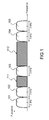
- the figure 1 represents an example of exploitation of the frequency spectrum HF according to the invention.
- the invention consists in dynamically selecting a set of frequency bands according to the quality, at a given moment, of the transmission on these frequency bands.
- the selected bands are not necessarily contiguous but taken in the set of frequencies allocated to the user. Certain frequency bands may also be reserved for other services and are therefore excluded from selection.
- the figure 1 represents the frequency spectrum in HF band.
- the frequency bands 101,102,103,104,105, of identical widths equal to 3 kHz are selected at a given instant for the transmission.
- the 111,112 frequency bands are not used because the estimated quality of the transmission on the latter does not allow to reach an optimum rate.
- the frequency band allocated to the HF communication is increased from 3 kHz to 15 kHz, the transmission being performed in parallel on all selected frequencies.
- the method according to the invention whose purpose is to increase the bandwidth available for HF transmission, comprises in particular the following steps.
- a subset S of the frequency band HF is chosen.
- the width of this subband S is a multiple of the channel of an HF transmission.
- the channel is equal to 3 kHz and the width of the subband S is therefore a multiple of 3 kHz.
- the total width of the sub-band S is limited so as not to complicate the equipment, in particular the formatting filters, the amplifier in transmission, and the tuning box of the antenna as well as the equalizer in reception.
- a good compromise between complexity and rate increase is, for example, to choose a 200 kHz sub-band.
- the subband S is defined from planning elements, that is to say according to the frequency bands allocated to the user.
- the sub-band S must contain a maximum of frequencies allocated to the user.
- the choice is also made according to predictions of the quality of transmission from models of the ionospheric layers as a function of time and frequency. These models can be determined, for example, using a software for predicting the propagation of HF waves and ionospheric layer analysis such as the known software VOACAP or by an ionosphere analysis by a method of three-dimensional tomography.
- the method according to the invention consists in a second step in selecting a number n of channels from the set of available channels in the sub-band S.
- the number n is fixed according to the factor bandwidth increase, and indirectly useful rate, desired.
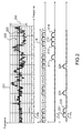
- the figure 2 illustrates an exemplary embodiment of the selection of n channels according to the invention.
- an analysis of the spectrum of the subband S is carried out.
- the power of the received signal throughout the sub-band S is measured, in the absence of transmission, channels per channel, in order to determine a note of quality of the transmission in each channel.
- This measurement is carried out by the receiver with a known digital analog converter 200 dynamic and saturation value 201.
- the quality score of the transmission may also take into account a value of the average power of the signal during a period of time spent.
- This average power is exploitable only if its measurement is carried out over a period of time for which the transmission and reception conditions are comparable with those observed for the measurement of the instantaneous power of the signal.
- comparable conditions are meant conditions that are similar geographically and ionosphereally. For example, measurements made during the day should not be compared with others made at night. Indeed, the ionosphere layer D dissipates at night which can cause fluctuations in the average power of the signal.
- the measurement of the instantaneous power of the signal is weighted by preferential allocations to different services. For example, if one has allocated frequencies of one's own and others in shared access, one will be able to favor the use of the frequencies in one's own.
- a threshold 202,203 for comparison to this quality score is fixed beyond which the channel is considered disturbed and therefore unavailable.
- several thresholds 202, 203 may be considered in order to define increasing quality scores as a function of the power of the spurious signals measured in the frequency channel.
- the threshold 203 corresponds to the maximum power of parasitic signals that can be supported so that the quality of the useful communication is good.
- the threshold 202 corresponds to an average quality with a communication signal affected in part by the disturbances of the ionosphere.
- a quality score is assigned to each channel, identified by its central frequency.
- two thresholds are used inducing three notes of increasing quality B, A and G.
- the channels 211,212,213,214 are selected so as to increase the bandwidth by a factor of four.
- These channels are chosen at least according to their quality score and among the frequencies actually allocated by the ITU to the user.
- other channels 221,222,223,224 are selected if the quality score of the previous channels is degraded.
- the broadband receiver according to the invention instantaneously scans the whole of the sub-band S.
- the receiver according to the invention may be forced to seek a new sub-band S.
- the figure 3 describes a flowchart grouping the implementation steps of the method according to the invention at a given instant t.
- the useful subband S is chosen in the frequency band HF from at least the frequency allocation plan 301 of the user and predictions 302 of the quality of the transmission in the different frequency channels of the HF band.
- an evaluation of the channels with a given spectral width equal for example to 3 kHz, is performed to determine whether they can support a communication.
- a quality score is assigned to each channel of the useful sub-band S.
- a test is performed on the number of channels that can support a communication.
- the channels for which the quality score is below a minimum threshold are eliminated from the method because they do not have the minimum availability required for the transmission of a call. If the number of channels retained is less than the minimum number of channels n_min required for transmission, the method returns to step 310 to look for a new subband S which has a better availability. If the number of available channels is greater than the minimum number of channels n_min but smaller than the desired number n of channels, the communication can still be established in a degraded mode. The operating time in a degraded mode can be limited in time. Alternatively, several successive evaluations can be performed on the same sub-band S before returning to step 310.
- a number n of channels is selected according to at least the quality score assigned to them and the frequency allocation plan 301.
- the n channels selected at a time t are compared with the n selected and stored channels at an earlier time t-1.
- the n selected channels are transmitted to the transmitter for a next phase resignation. If the n selected channels have not been changed between times t-1 and t, then the method is looped at step 311 for evaluating the channels of the useful sub-band S.
- the figure 4 represents a block diagram of an HF band communication system according to the invention.
- the spectrum analysis as well as the selection of the n channels in the subband S is carried out by the receiver 402 which periodically transmits this information to the transmitter via a return channel 410.
- transmitter 401 has received the information of the n frequency channels on which it can transmit, it carries out a simultaneous transmission on all n available channels.
- the transmitted signal respects a known RF waveform and is multiplexed on the n channels to allow an increase in the useful rate by a factor n.
- the emitted power is concentrated on these n channels and is not spread throughout the sub-band S.
- the Receiver 402 determines a new available channel and transmits its center frequency to transmitter 401.
- the transmitter and receiver clocks are synchronized to switch synchronously to the new frequency plan.
- the receiver 402 thus comprises means 403 adapted to implement the method of selecting n frequency channels in a sub-band S.
- the transmitter 401 comprises means 404 adapted to receive information specifying the n frequency channels on which ones to emit.
- the spectrum analysis and the selection of the n channels in the sub-band S is performed by the receiver which periodically transmits this information to the transmitter via a return channel.
- the transmitter As soon as the transmitter is aware of the frequencies on which it can transmit, it transmits simultaneously on all n available channels.
- the transmitted signal respects a known RF waveform and is multiplexed on the n channels to allow an increase in the useful rate by a factor n.
- the emitted power is concentrated on these n channels and is not spread throughout the sub-band S.
- the receiver determines a new available channel and transmits its center frequency to the transmitter.
- the clocks of the transmitter and the receiver are synchronized to switch synchronously to the new frequency plan.
- the method and system according to the invention have the following advantages.
- the increase of the bandwidth and the useful rate is done by taking into account the temporal evolution of the physical availability of each channel subjected to disturbances mainly related to the reflections of signals on the layers of the ionosphere, to the communications in neighboring channels, or changes due to a displacement of the emitter or receiver communicating as a surface wave.
- the invention allows an increase in the spectral resources while respecting the frequency allocation plan in the HF band for a given user.
- the invention also allows an increase in the useful rate without degrading the scope of the transmission and the probability of establishment of the link.
Abstract
Description
L'invention concerne le domaine des radiocommunications dans la bande de fréquences HF (« Hautes Fréquences») qui va de 3 MHz à 30 MHz. L'invention se rapporte plus précisément à l'augmentation de débit pour de telles communications.The invention relates to the field of radio communications in the frequency band HF ("High Frequencies") which ranges from 3 MHz to 30 MHz. The invention relates more specifically to the rate increase for such communications.
Les liaisons HF offrent une capacité hors ligne de vue qui permet de réaliser des communications à longue voire très longue distance sans nécessiter le recours à un satellite pour effectuer un relai de la transmission.HF links provide an off-line capability that allows for long-distance or long-distance communications without the need for a satellite to relay the transmission.
Les ondes radios dont la fréquence est comprise dans la bande HF, encore appelées ondes décamétriques en référence à leur longueur d'onde qui est comprise entre 10 et 100 mètres, se propagent le plus souvent selon deux modes alternatifs.The radio waves whose frequency is included in the band HF, still called HF in reference to their wavelength which is between 10 and 100 meters, propagate most often according to two alternative modes.
Dans un premier mode de propagation, dit ionosphérique, les ondes radios HF subissent une réflexion sur les différentes couches de l'ionosphère. Ces couches n'étant pas stables dans le temps ni dans l'espace, elles entrainent de fortes variations du canal de propagation ce qui provoque des instabilités et donc une baisse du débit disponible. La capacité de liaisons HF se propageant dans un mode ionosphérique est ainsi limitée en termes de débit de transmission disponible.In a first ionospheric propagation mode, the radio waves HF undergo a reflection on the different layers of the ionosphere. These layers are not stable in time or in space, they cause large variations in the propagation channel which causes instabilities and therefore a decrease in available flow. The capacity of HF links propagating in an ionospheric mode is thus limited in terms of available transmission rate.
Dans un second mode de propagation, dit de surface, les ondes radios HF se propagent en ondes de sol. La distance maximale de propagation dépend alors fortement de la composition de la surface terrestre sur le trajet entre l'émetteur et le récepteur. En effet, une surface très conductive, comme l'eau salée par exemple, offre une portée bien supérieure à un sol de type rocheux par exemple. Si les types de surface varient bien moins dans le temps que les couches de l'ionosphère, la propagation des ondes radios HF en mode de surface reste très variable d'un endroit à un autre du globe. Cet aspect présente un impact notamment en cas de mobilité de l'émetteur ou du récepteur.In a second mode of propagation, called surface, the radio waves HF propagate in ground waves. The maximum propagation distance then strongly depends on the composition of the earth's surface on the path between the transmitter and the receiver. Indeed, a very conductive surface, such as salt water for example, offers a much greater range than a rock type soil for example. Although the surface types vary much less in time than the ionosphere layers, the propagation of HF radio waves in surface mode remains very variable from one place to another. other of the globe. This aspect has an impact especially in the case of mobility of the transmitter or receiver.
Les fréquences disponibles dans la bande HF sont allouées aux divers utilisateurs par l'Union Internationale des Télécommunications (UIT). Une canalisation classiquement utilisée par des systèmes de communications HF en onde de sol ou en onde ionosphérique est de l'ordre de 3 KHz éventuellement doublée pour passer à 6kHz. Le mode de modulation couramment utilisé est celui de la bande latérale unique BLU ou « Single Side Bande » SSB en anglais. Cette canalisation est imposée par les standards définissant les formes d'ondes HF.The frequencies available in the HF band are allocated to the various users by the International Telecommunications Union (ITU). A channel conventionally used by ground-wave or ionospheric HF communication systems is of the order of 3 KHz possibly doubled to 6 kHz. The modulation mode commonly used is that of the single sideband SSB or SSB "Single Side Band" in English. This channel is imposed by the standards defining the HF waveforms.
La limitation de largeur de bande imposée par la canalisation de 3 kHz pose le problème de la limitation du débit utile qui peut être envisagé pour une transmission HF. Du fait de la faible largeur de bande, mais également des limitations induites par le canal de propagation ionosphérique ou en onde de surface, les débits atteints ne dépassent pas la dizaine de kilobits par seconde. A titre d'exemple, la valeur typique maximale des standards actuels est de 9600 bits par seconde pour 3 kHz de bande passante. Pour des applications nécessitant des ressources plus élevées, telles que les applications internet ou de visiophonie par exemple, le débit utile proposé par les formes d'ondes HF existantes n'est pas suffisant.The bandwidth limitation imposed by the 3 kHz pipeline raises the problem of limiting the useful rate that can be envisaged for HF transmission. Due to the small bandwidth, but also the limitations induced by the ionospheric propagation channel or surface wave, the flow rates reached do not exceed ten kilobits per second. For example, the typical maximum value of current standards is 9600 bits per second for 3 kHz bandwidth. For applications requiring higher resources, such as internet applications or video telephony for example, the useful bandwidth proposed by the existing RF waveforms is not sufficient.
De plus, les bandes de fréquences allouées à un même utilisateur ne sont en général pas contigües et sont réparties dans l'ensemble de la bande HF selon un plan de fréquence imposé.In addition, the frequency bands allocated to the same user are generally not contiguous and are distributed throughout the HF band according to a prescribed frequency plan.
Le problème se pose donc de l'augmentation du débit utile tout en respectant les contraintes spécifiques des communications HF et particulièrement des communications HF en mode ionosphérique.The problem therefore arises of increasing the useful rate while respecting the specific constraints of HF communications and particularly ionospheric HF communications.
Une solution connue permettant de lutter contre les instabilités du canal de propagation HF consiste à effectuer une recherche automatique de fréquence disponible parmi celles allouées à l'utilisateur. Cette procédure est effectuée de façon initiale ou après rupture de la communication d'un lien mais ne permet pas de prendre en compte finement et de façon dynamique l'évolution temporelle de la disponibilité du médium.A known solution for controlling the instabilities of the HF propagation channel is to perform an automatic frequency search available among those allocated to the user. This procedure is performed initially or after breaking the communication of a link but does not allow to take into account finely and dynamically the temporal evolution of the availability of the medium.
L'augmentation du débit utile est envisagée classiquement selon deux méthodes. Une première solution iso-bande consiste à conserver la canalisation imposée et à augmenter l'efficacité spectrale de la modulation et/ou le rendement du codage correcteur protégeant la communication contre les instabilités du canal. Cette solution présente une limite théorique en débit atteignable imposée par la canalisation et de plus l'augmentation du rendement du codage correcteur pénalise la liaison en réduisant la portée et la probabilité d'établissement de la communication.The increase of the useful flow is considered conventionally according to two methods. A first iso-band solution consists of conserving the imposed channel and increasing the spectral efficiency of the modulation and / or the efficiency of the correction coding protecting the communication against the instabilities of the channel. This solution has a theoretical limit in achievable flow imposed by the pipe and in addition the increase in the efficiency of the correction coding penalizes the link by reducing the range and the probability of establishment of the communication.
Une seconde solution consiste à augmenter la largeur de la canalisation en prenant en compte les canaux adjacents. Cette solution présente plusieurs inconvénients. Tout d'abord la complexité des systèmes, émetteurs et récepteurs, est accrue avec l'augmentation de la bande de fréquence utile. Pour l'émetteur, la réalisation du filtre de mise en forme large bande et surtout celle de l'amplificateur de puissance et du synthétiseur de fréquences est d'autant plus complexe que la bande de fréquence est grande. Pour le récepteur, c'est la réalisation de l'égaliseur qui est rendue plus complexe avec l'augmentation de la bande utile. D'autre part, les canaux contigus ne sont pas, le plus souvent, ceux qui présentent la meilleure disponibilité physique et peuvent être impactés par les perturbations liées à la couche ionosphérique déjà mentionnées. En effet, le medium HF étant très fluctuant, il est peu probable d'avoir un grand nombre de canaux contigus disponibles physiquement et qui permettraient d'obtenir les débits utiles envisagés. Enfin, d'un point de vue légal, les bandes de fréquences allouées à un utilisateur par l'ITU ne peuvent aisément être modifiées pour exploiter plusieurs bandes contigües. Au contraire le plan de fréquences alloué correspond le plus souvent à un ensemble de fréquences réparties dans l'ensemble de la bande HF de façon à pouvoir sécuriser les transmissions par l'application de méthodes de saut de fréquence ou de limiter la probabilité d'utiliser une fréquence qui soit perturbée.A second solution is to increase the width of the pipeline taking into account the adjacent channels. This solution has several disadvantages. First of all, the complexity of the systems, transmitters and receivers, is increased with the increase of the useful frequency band. For the transmitter, the realization of the broadband formatting filter and especially that of the power amplifier and the frequency synthesizer is even more complex than the frequency band is large. For the receiver, it is the realization of the equalizer which is made more complex with the increase of the useful band. On the other hand, the contiguous channels are not, in most cases, those which have the best physical availability and can be impacted by the disturbances related to the ionospheric layer already mentioned. Indeed, the medium HF being very fluctuating, it is unlikely to have a large number of contiguous channels available physically and which would obtain the desired flow rates envisaged. Finally, from a legal point of view, the frequency bands allocated to a user by the ITU can not easily be modified to exploit several contiguous bands. On the contrary, the allocated frequency plan most often corresponds to a set of frequencies distributed throughout the HF band so as to be able to secure the transmissions by the application of frequency hopping methods or to limit the probability of using them. a frequency that is disturbed.
Afin de résoudre les limitations précitées des solutions connues, l'invention propose une approche permettant d'augmenter la bande de fréquence utile sans exploiter de canaux contigus et sans augmenter significativement la complexité des équipements.In order to solve the aforementioned limitations of the known solutions, the invention proposes an approach making it possible to increase the useful frequency band without exploiting contiguous channels and without significantly increasing the complexity of the equipment.
L'invention a ainsi pour objet un procédé de communications adaptatives dans une bande de fréquences HF caractérisé en ce qu'il comporte au moins les étapes suivantes :
- o la détermination d'une sous-bande utile S disponible pour une transmission dans la bande HF, en fonction d'au moins un des deux critères suivants :
- ■ le nombre de fréquences allouées à l'utilisateur comprises dans la sous-bande utile S selon ledit plan d'allocation de fréquences,
- ■ la disponibilité physique de la sous-bande utile S évaluée en fonction d'une prédiction des perturbations induites sur le signal par les réflexions sur les couches ionosphériques.
- o la sélection dans la sous-bande utile S, d'un ensemble de n canaux fréquentiels de largeur identique en fonction d'un plan d'allocation de fréquences et de la qualité de la liaison de chacun desdits canaux,
- o la transmission simultanée sur les n canaux fréquentiels d'un signal respectant une forme d'onde HF.
- o determining a useful sub-band S available for transmission in the HF band, according to at least one of the following two criteria:
- The number of frequencies allocated to the user included in the useful sub-band S according to said frequency allocation plan,
- The physical availability of the useful sub-band S evaluated according to a prediction of the perturbations induced on the signal by the reflections on the ionospheric layers.
- o the selection in the useful subband S, of a set of n frequency channels of identical width according to a frequency allocation plan and the quality of the link of each of said channels,
- the simultaneous transmission on the n frequency channels of a signal respecting an HF waveform.
Dans une variante de réalisation de l'invention, la qualité de la liaison de chacun desdits canaux est estimée au moins à partir des sous-étapes suivantes :
- o la mesure de la puissance du signal reçu, en l'absence de communication, dans chaque canal fréquentiel que comporte la sous-bande utile S,
- o l'attribution d'une note de qualité à chacun desdits canaux fréquentiels en fonction de la comparaison de ladite puissance à un ou plusieurs seuils prédéterminés, ladite qualité étant décroissante avec la croissance de la puissance,
- o la sélection des n canaux présentant les notes de qualité les plus élevées.
- o the measurement of the power of the received signal, in the absence of communication, in each frequency channel that comprises the useful subband S,
- o assigning a quality score to each of said frequency channels according to the comparison of said power to one or more predetermined thresholds, said quality being decreasing with the growth of the power,
- o selection of the n channels with the highest quality ratings.
Dans une variante de réalisation de l'invention, la sélection dudit ensemble de n canaux fréquentiels est mise à jour périodiquement ou dès que la note de qualité d'un canal sélectionné est dégradée.In an alternative embodiment of the invention, the selection of said set of n frequency channels is periodically updated or as soon as the quality score of a selected channel is degraded.
Dans une variante de réalisation le procédé selon l'invention comporte en outre l'étape de test suivante :
- o déterminer le nombre de canaux fréquentiels pour lesquels la qualité de la liaison est supérieure à un seuil minimum requis pour qu'une transmission soit possible sur ces canaux,
- o si ledit nombre est inférieur au nombre n de canaux requis pour la transmission, déterminer une autre sous-bande utile S disponible.
- o determine the number of frequency channels for which the quality of the link is higher than a minimum threshold required for transmission to be possible on these channels,
- o if said number is smaller than the number n of channels required for transmission, determining another available useful sub-band S.
Dans une variante de réalisation de l'invention, la qualité de la liaison de chacun desdits canaux est estimée en outre à l'aide d'une mesure de la puissance moyenne du signal reçu sur une période de temps antérieure.In an alternative embodiment of the invention, the quality of the link of each of said channels is further estimated using a measure of the average power of the received signal over a previous period of time.
Dans une variante de réalisation de l'invention, la largeur d'un canal fréquentiel est égale à 3 kHz.In an alternative embodiment of the invention, the width of a frequency channel is equal to 3 kHz.
L'invention a également pour objet un système de communications en bande HF comportant au moins un émetteur HF et un récepteur HF adaptés à émettre et recevoir un signal de forme d'onde HF caractérisé en ce que :
- o ledit récepteur HF comporte des moyens pour déterminer une sous-bande utile S disponible pour une transmission dans la bande HF, et pour sélectionner, dans la sous-bande utile S, un ensemble de n canaux fréquentiels de largeur identique en fonction d'un plan d'allocation de fréquences et de la qualité de la liaison de chacun desdits canaux et transmettre audit émetteur HF ledit ensemble de n canaux fréquentiels sélectionnés,
- o ledit émetteur HF comporte des moyens pour recevoir un ensemble de n canaux fréquentiels sélectionnés et transmettre simultanément sur les n canaux fréquentiels un signal respectant ladite forme d'onde HF,
- o ledit système de communications comportant en outre des moyens pour mettre en oeuvre le procédé de communications adaptatives selon l'invention.
- said HF receiver comprises means for determining a useful sub-band S available for transmission in the HF band, and for selecting, in the useful sub-band S, a set of n frequency channels of identical width as a function of a frequency allocation plan and the quality of the link of each of said channels and transmit to said RF transmitter said set of n selected frequency channels,
- said RF transmitter comprises means for receiving a set of n selected frequency channels and transmitting simultaneously on the n frequency channels a signal respecting said RF waveform,
- said communication system further comprising means for implementing the adaptive communications method according to the invention.
D'autres caractéristiques et avantages de l'invention apparaîtront à l'aide de la description qui suit faite en regard des dessins annexés qui représentent :
- la
figure 1 , une illustration du principe d'utilisation de canaux non contigus selon l'invention, - la
figure 2 , une illustration de la mise en oeuvre du procédé selon l'invention, - la
figure 3 , un organigramme décrivant les étapes de mise en oeuvre du procédé selon l'invention, - la
figure 4 , un synoptique d'un système de communications en bande HF selon l'invention.
- the
figure 1 , an illustration of the principle of using non-contiguous channels according to the invention, - the
figure 2 an illustration of the implementation of the method according to the invention, - the
figure 3 a flowchart describing the steps for implementing the method according to the invention, - the
figure 4 , a block diagram of an HF band communication system according to the invention.
La
Le procédé selon l'invention, dont un but est d'augmenter la bande passante disponible pour la transmission HF, comporte notamment les étapes suivantes. Dans un premier temps une sous-partie S de la bande de fréquences HF est choisie. La largeur de cette sous-bande S est un multiple de la canalisation d'une transmission HF. Préférentiellement, la canalisation est égale à 3 kHz et la largeur de la sous-bande S est donc un multiple de 3 kHz. La largeur totale de la sous-bande S est limitée de façon à ne pas complexifier les équipements, en particulier les filtres de mise en forme, l'amplificateur en émission, et la boîte d'accord de l'antenne ainsi que l'égaliseur en réception. Pour une canalisation de 3 kHz, un bon compromis entre complexité et augmentation du débit consiste, par exemple, à choisir une sous-bande de largeur 200 kHz. La sous-bande S est définie à partir d'éléments de planification, c'est-à-dire en fonction des bandes de fréquences allouées à l'utilisateur. Par exemple, la sous-bande S doit contenir un maximum de fréquences allouées à l'utilisateur. Le choix est également effectué en fonctions de prédictions de la qualité de la transmission à partir de modèles des couches ionosphériques en fonction du temps et de la fréquence. Ces modèles peuvent être déterminés, par exemple, à l'aide d'un logiciel de prédiction de la propagation des ondes HF et d'analyse des couches ionosphériques tel que le logiciel connu VOACAP ou par une analyse de l'ionosphère par une méthode de tomographie en trois dimensions.The method according to the invention, whose purpose is to increase the bandwidth available for HF transmission, comprises in particular the following steps. First, a subset S of the frequency band HF is chosen. The width of this subband S is a multiple of the channel of an HF transmission. Preferably, the channel is equal to 3 kHz and the width of the subband S is therefore a multiple of 3 kHz. The total width of the sub-band S is limited so as not to complicate the equipment, in particular the formatting filters, the amplifier in transmission, and the tuning box of the antenna as well as the equalizer in reception. For a 3 kHz channel, a good compromise between complexity and rate increase is, for example, to choose a 200 kHz sub-band. The subband S is defined from planning elements, that is to say according to the frequency bands allocated to the user. For example, the sub-band S must contain a maximum of frequencies allocated to the user. The choice is also made according to predictions of the quality of transmission from models of the ionospheric layers as a function of time and frequency. These models can be determined, for example, using a software for predicting the propagation of HF waves and ionospheric layer analysis such as the known software VOACAP or by an ionosphere analysis by a method of three-dimensional tomography.
Lorsque la sous-bande S est définie, le procédé selon l'invention consiste dans un deuxième temps à sélectionner un nombre n de canaux parmi l'ensemble des canaux disponibles dans la sous-bande S. Le nombre n est fixé en fonction du facteur d'augmentation de bande passante, et indirectement de débit utile, désiré.When the sub-band S is defined, the method according to the invention consists in a second step in selecting a number n of channels from the set of available channels in the sub-band S. The number n is fixed according to the factor bandwidth increase, and indirectly useful rate, desired.
La
Tout d'abord une analyse du spectre de la sous-bande S est réalisée. La puissance du signal reçu dans toute la sous-bande S est mesurée, en l'absence de transmission, canaux par canaux, afin de déterminer une note de qualité de la transmission dans chaque canal. Cette mesure est effectuée par le récepteur avec un convertisseur analogique numérique de dynamique 200 et de valeur de saturation 201 connues.Firstly, an analysis of the spectrum of the subband S is carried out. The power of the received signal throughout the sub-band S is measured, in the absence of transmission, channels per channel, in order to determine a note of quality of the transmission in each channel. This measurement is carried out by the receiver with a known
Dans une variante de réalisation de l'invention, la note de qualité de la transmission peut également prendre en compte une valeur de la puissance moyenne du signal au cours d'une période de temps passée. Cette puissance moyenne est exploitable uniquement si sa mesure est réalisée sur une période de temps pour laquelle les conditions d'émission et de réception sont comparables avec celles observées pour la mesure de la puissance instantanée du signal. Par conditions comparables, on entend des conditions similaires du point de vue géographique comme du point de vue ionosphérique. Par exemple, Il convient de ne pas comparer des mesures réalisées le jour avec d'autres réalisées la nuit. En effet la couche D de l'ionosphère se dissipe la nuit ce qui peut entrainer des fluctuations sur la puissance moyenne du signal.In an alternative embodiment of the invention, the quality score of the transmission may also take into account a value of the average power of the signal during a period of time spent. This average power is exploitable only if its measurement is carried out over a period of time for which the transmission and reception conditions are comparable with those observed for the measurement of the instantaneous power of the signal. By comparable conditions are meant conditions that are similar geographically and ionosphereally. For example, measurements made during the day should not be compared with others made at night. Indeed, the ionosphere layer D dissipates at night which can cause fluctuations in the average power of the signal.
Dans une autre variante de réalisation de l'invention, la mesure de la puissance instantanée du signal est pondérée par des allocations préférentielles à différents services. Par exemple si l'on dispose de fréquences attribuées en propre et d'autres en accès partagé, on pourra favoriser l'utilisation des fréquences en propre.In another variant embodiment of the invention, the measurement of the instantaneous power of the signal is weighted by preferential allocations to different services. For example, if one has allocated frequencies of one's own and others in shared access, one will be able to favor the use of the frequencies in one's own.
Une fois la note de qualité de la transmission dans chaque canal établie, au moins un seuil 202,203 de comparaison à cette note de qualité est fixé au delà duquel le canal est considéré comme perturbé et donc non disponible. En pratique, plusieurs seuils 202,203 peuvent être envisagés afin de définir des notes de qualité croissantes en fonction de la puissance des signaux parasites mesurée dans le canal fréquentiel. Dans l'exemple de la
Lorsque l'analyse du spectre est effectuée pour l'ensemble des canaux de la sous-bande S, une note de qualité est attribuée à chaque canal, identifié par sa fréquence centrale. Dans l'exemple de la
Le récepteur large bande selon l'invention numérise instantanément l'ensemble de la sous-bande S. Dans le cas où un canal particulièrement perturbé amènerait une dégradation trop forte de la sensibilité en réception le récepteur selon l'invention peut être contraint à rechercher une nouvelle sous-bande S.The broadband receiver according to the invention instantaneously scans the whole of the sub-band S. In the case where a particularly disturbed channel would lead to an excessive degradation of the sensitivity in reception, the receiver according to the invention may be forced to seek a new sub-band S.
La
Dans une quatrième étape 313, un nombre n de canaux est sélectionné en fonction au moins de la note de qualité qui leur est attribuée et du plan d'allocations de fréquences 301. Dans une cinquième étape 314, les n canaux sélectionnés à un instant t sont comparés avec les n canaux sélectionnés et mémorisés à un instant t-1 antérieur. Dans une sixième étape 315, si au moins un canal, parmi les n canaux sélectionnés, est modifié entre l'instant antérieur t-1 et l'instant ultérieur t, alors les n canaux sélectionnés sont transmis à l'émetteur pour une prochaine phase d'émission. Si les n canaux sélectionnés n'ont pas été modifiés entre les instant t-1 et t, alors le procédé boucle à l'étape 311 d'évaluation des canaux de la sous-bande utile S.In a
La
L'analyse du spectre ainsi que la sélection des n canaux dans la sous-bande S est effectuée par le récepteur 402 qui transmet, périodiquement, ces informations à l'émetteur par l'intermédiaire d'une voie de retour 410. Dès que l'émetteur 401 a reçu l'information des n canaux fréquentiels sur lesquels il peut émettre, il effectue une transmission simultanée sur tous les n canaux disponibles. Le signal transmis respecte une forme d'onde HF connue et est multiplexé sur les n canaux afin de permettre une augmentation du débit utile d'un facteur n. La puissance émise est concentrée sur ces n canaux et n'est pas étalée dans toute la sous-bande S. Lorsqu'un changement de canaux fréquentiels intervient, du fait d'un changement de la note de qualité d'un canal utilisé, le récepteur 402 détermine un nouveau canal disponible et transmet sa fréquence centrale à l'émetteur 401. Les horloges de l'émetteur et du récepteur sont synchronisées de façon à basculer de façon synchrone sur le nouveau plan de fréquences. Le récepteur 402 comporte ainsi des moyens 403 adaptés à mettre en oeuvre le procédé de sélection de n canaux fréquentiels dans une sous-bande S. L'émetteur 401 comporte des moyens 404 adaptés à la réception de l'information spécifiant les n canaux fréquentiels sur lesquels émettre.The spectrum analysis as well as the selection of the n channels in the subband S is carried out by the
L'analyse du spectre ainsi que la sélection des n canaux dans la sous-bande S est effectuée par le récepteur qui transmet, périodiquement, ces informations à l'émetteur par l'intermédiaire d'une voie de retour. Dès que l'émetteur a connaissance des fréquences sur lesquelles il peut émettre, il effectue une transmission simultanée sur tous les n canaux disponibles. Le signal transmis respecte une forme d'onde HF connue et est multiplexé sur les n canaux afin de permettre une augmentation du débit utile d'un facteur n. La puissance émise est concentrée sur ces n canaux et n'est pas étalée dans toute la sous-bande S. Lorsqu'un changement de canaux fréquentiels intervient, du fait d'un changement de la note de qualité d'un canal utilisé, le récepteur détermine un nouveau canal disponible et transmet sa fréquence centrale à l'émetteur. Les horloges de l'émetteur et du récepteur sont synchronisées de façon à basculer de façon synchrone sur le nouveau plan de fréquences.The spectrum analysis and the selection of the n channels in the sub-band S is performed by the receiver which periodically transmits this information to the transmitter via a return channel. As soon as the transmitter is aware of the frequencies on which it can transmit, it transmits simultaneously on all n available channels. The transmitted signal respects a known RF waveform and is multiplexed on the n channels to allow an increase in the useful rate by a factor n. The emitted power is concentrated on these n channels and is not spread throughout the sub-band S. When a change of frequency channels occurs, because of a change in the quality score of a channel used, the receiver determines a new available channel and transmits its center frequency to the transmitter. The clocks of the transmitter and the receiver are synchronized to switch synchronously to the new frequency plan.
Le procédé et le système selon l'invention présentent les avantages suivants. L'augmentation de la bande passante et du débit utile se fait en prenant en compte l'évolution temporelle de la disponibilité physique de chaque canal soumis à des perturbations principalement liées aux réflexions de signaux sur les couches de l'ionosphère, aux communications dans des canaux voisins, ou aux changements liés à un déplacement de l'émetteur ou du récepteur communiquant en onde de surface. L'invention permet une augmentation des ressources spectrales tout en respectant le plan d'allocation de fréquences dans la bande HF pour un utilisateur donné. L'invention permet également une augmentation du débit utile sans dégrader la portée de la transmission et la probabilité d'établissement de la liaison.The method and system according to the invention have the following advantages. The increase of the bandwidth and the useful rate is done by taking into account the temporal evolution of the physical availability of each channel subjected to disturbances mainly related to the reflections of signals on the layers of the ionosphere, to the communications in neighboring channels, or changes due to a displacement of the emitter or receiver communicating as a surface wave. The invention allows an increase in the spectral resources while respecting the frequency allocation plan in the HF band for a given user. The invention also allows an increase in the useful rate without degrading the scope of the transmission and the probability of establishment of the link.
Claims (7)
Applications Claiming Priority (1)
| Application Number | Priority Date | Filing Date | Title |
|---|---|---|---|
| FR1004650A FR2968149B1 (en) | 2010-11-30 | 2010-11-30 | METHOD AND SYSTEM FOR ADAPTIVE HF BAND COMMUNICATIONS |
Publications (2)
| Publication Number | Publication Date |
|---|---|
| EP2458770A1 true EP2458770A1 (en) | 2012-05-30 |
| EP2458770B1 EP2458770B1 (en) | 2016-11-02 |
Family
ID=44262790
Family Applications (1)
| Application Number | Title | Priority Date | Filing Date |
|---|---|---|---|
| EP11191301.8A Active EP2458770B1 (en) | 2010-11-30 | 2011-11-30 | Adaptive communication method and system in HF band |
Country Status (7)
| Country | Link |
|---|---|
| US (1) | US9008594B2 (en) |
| EP (1) | EP2458770B1 (en) |
| CA (1) | CA2760435C (en) |
| FR (1) | FR2968149B1 (en) |
| IL (1) | IL216693A (en) |
| MY (1) | MY166990A (en) |
| SG (1) | SG181275A1 (en) |
Cited By (3)
| Publication number | Priority date | Publication date | Assignee | Title |
|---|---|---|---|---|
| EP2830342A1 (en) | 2013-07-25 | 2015-01-28 | Thales | Method for managing HF frequencies in broadband communications |
| EP2830256A1 (en) | 2013-07-25 | 2015-01-28 | Thales | Method for enhancing HF band connection using a broadband capacity |
| WO2016162429A1 (en) | 2015-04-10 | 2016-10-13 | Thales | Method of reducing the peak factor of a multichannel emission by intelligent and adaptive clipping/filtering |
Families Citing this family (5)
| Publication number | Priority date | Publication date | Assignee | Title |
|---|---|---|---|---|
| FR2981233B1 (en) | 2011-10-10 | 2014-07-25 | Thales Sa | METHOD AND SYSTEM FOR DYNAMIC POWER AND / OR MODULATION ALLOCATION IN A SYSTEM COMPRISING N-CHANNELS |
| FR2981232B1 (en) | 2011-10-10 | 2014-02-14 | Thales Sa | METHOD AND COMMUNICATION SYSTEM USING DYNAMIC MODULATION AND ENCODING SCHEMES ON BROADBAND HF COMMUNICATION CHANNELS |
| FR2998120B1 (en) | 2012-11-09 | 2014-11-21 | Thales Sa | METHOD AND SYSTEM FOR CHANNEL DESYNCHRONIZATION IN MULTI-CARRIER COMMUNICATION SYSTEMS |
| EP3230762A4 (en) * | 2014-12-12 | 2018-08-15 | Services Development Company LLC | Data transmission via a high frequency radio band |
| RU2643237C2 (en) * | 2016-06-29 | 2018-02-01 | Акционерное общество "Омский научно-исследовательский институт приборостроения" (АО "ОНИИП") | Method of multiparameter adaptation |
Citations (1)
| Publication number | Priority date | Publication date | Assignee | Title |
|---|---|---|---|---|
| EP1492280A1 (en) * | 2003-06-24 | 2004-12-29 | Samsung Electronics Co., Ltd. | Quality driven adaptive channel assignment in an OFDMA radio communication system |
Family Cites Families (12)
| Publication number | Priority date | Publication date | Assignee | Title |
|---|---|---|---|---|
| IL67379A (en) * | 1982-12-01 | 1985-11-29 | Tadiran Israel Elect Ind Ltd | Real-time frequency management system for hf communication networks |
| GB8909051D0 (en) * | 1989-04-21 | 2001-04-11 | Secr Defence | A high data rate multiplexed multichannel high frequency broadcast system |
| WO1992019982A1 (en) | 1991-05-02 | 1992-11-12 | THE COMMONWEALTH OF AUSTRALIA c/o THE SECRETARY, DEPARTMENT OF DEFENCE | Operational channel selection |
| FI120711B (en) | 1995-02-06 | 2010-01-29 | Adc Telecommunications Inc | Multipoint to point communication system |
| WO1999009650A1 (en) * | 1997-08-21 | 1999-02-25 | Data Fusion Corporation | Method and apparatus for acquiring wide-band pseudorandom noise encoded waveforms |
| BR9815914A (en) | 1998-06-19 | 2001-02-20 | Ericsson Telefon Ab L M | Processes for use in packet data communications and in a communications system, and, controller and device in a communications system. |
| US7027418B2 (en) * | 2001-01-25 | 2006-04-11 | Bandspeed, Inc. | Approach for selecting communications channels based on performance |
| WO2004023748A1 (en) | 2002-09-05 | 2004-03-18 | South Land Communications Pty Ltd | A system to deliver internet media streams, data & telecommunications |
| US8170081B2 (en) * | 2004-04-02 | 2012-05-01 | Rearden, LLC. | System and method for adjusting DIDO interference cancellation based on signal strength measurements |
| US8571086B2 (en) * | 2004-04-02 | 2013-10-29 | Rearden, Llc | System and method for DIDO precoding interpolation in multicarrier systems |
| JPWO2006077696A1 (en) | 2005-01-18 | 2008-06-19 | シャープ株式会社 | Wireless communication device, portable terminal, and wireless communication method |
| US8054894B2 (en) | 2005-10-31 | 2011-11-08 | Motorola Mobility, Inc. | Method and apparatus for providing channel quality feedback in an orthogonal frequency division multiplexing communication system |
-
2010
- 2010-11-30 FR FR1004650A patent/FR2968149B1/en not_active Expired - Fee Related
-
2011
- 2011-11-30 US US13/308,174 patent/US9008594B2/en active Active
- 2011-11-30 SG SG2011089174A patent/SG181275A1/en unknown
- 2011-11-30 CA CA2760435A patent/CA2760435C/en active Active
- 2011-11-30 MY MYPI2011005806A patent/MY166990A/en unknown
- 2011-11-30 IL IL216693A patent/IL216693A/en active IP Right Grant
- 2011-11-30 EP EP11191301.8A patent/EP2458770B1/en active Active
Patent Citations (1)
| Publication number | Priority date | Publication date | Assignee | Title |
|---|---|---|---|---|
| EP1492280A1 (en) * | 2003-06-24 | 2004-12-29 | Samsung Electronics Co., Ltd. | Quality driven adaptive channel assignment in an OFDMA radio communication system |
Cited By (8)
| Publication number | Priority date | Publication date | Assignee | Title |
|---|---|---|---|---|
| EP2830342A1 (en) | 2013-07-25 | 2015-01-28 | Thales | Method for managing HF frequencies in broadband communications |
| EP2830256A1 (en) | 2013-07-25 | 2015-01-28 | Thales | Method for enhancing HF band connection using a broadband capacity |
| FR3009160A1 (en) * | 2013-07-25 | 2015-01-30 | Thales Sa | METHOD FOR IMPROVING HF BAND CONNECTION USING BROADBAND CAPACITY |
| FR3009152A1 (en) * | 2013-07-25 | 2015-01-30 | Thales Sa | METHOD OF MANAGING RF FREQUENCIES IN BROADBAND USE |
| US9480094B2 (en) | 2013-07-25 | 2016-10-25 | Thales | Method for improving the HF band link establishment using a broadband capability |
| US9660790B2 (en) | 2013-07-25 | 2017-05-23 | Thales | Method for managing HF frequencies in broadband use |
| WO2016162429A1 (en) | 2015-04-10 | 2016-10-13 | Thales | Method of reducing the peak factor of a multichannel emission by intelligent and adaptive clipping/filtering |
| US10425266B2 (en) | 2015-04-10 | 2019-09-24 | Thales | Method for reducing the peak factor of a multichannel emission by adaptive and intelligent clipping/filtering |
Also Published As
| Publication number | Publication date |
|---|---|
| IL216693A (en) | 2016-08-31 |
| CA2760435C (en) | 2018-03-20 |
| US9008594B2 (en) | 2015-04-14 |
| US20120309330A1 (en) | 2012-12-06 |
| IL216693A0 (en) | 2012-03-29 |
| CA2760435A1 (en) | 2012-05-30 |
| FR2968149A1 (en) | 2012-06-01 |
| BRPI1107037A2 (en) | 2015-07-28 |
| EP2458770B1 (en) | 2016-11-02 |
| SG181275A1 (en) | 2012-06-28 |
| FR2968149B1 (en) | 2013-03-15 |
| MY166990A (en) | 2018-07-27 |
Similar Documents
| Publication | Publication Date | Title |
|---|---|---|
| EP2458770B1 (en) | Adaptive communication method and system in HF band | |
| EP1770885B1 (en) | Method and system for automatically planning delays between transmitting times of transmitters in a synchronous single frequency network | |
| FR2941126A1 (en) | METHODS FOR CONFIGURING TRANSMIT AND RECEIVE ANTENNAS, COMPUTER PROGRAM PRODUCT, STORAGE MEDIUM, AND CORRESPONDING NODES | |
| EP0397546B1 (en) | Method and apparatus for information transmission between radio transceivers of the same frequency hopping network | |
| EP2394474B1 (en) | Transmission method in a wireless network and corresponding reception method | |
| EP3075088A1 (en) | Method of coordinating radio transmitters based on a coding of level of power transmitted and corresponding transmitter | |
| FR2765052A1 (en) | POLARIZED CODE DIFFERENCE MULTIPLE ACCESS SIGNAL TRANSMISSION AND RECEPTION SYSTEM | |
| FR2935493A1 (en) | METHOD AND DEVICE FOR MONITORING ANTENNA | |
| EP2605423B1 (en) | Satellite transmission system with commutation between low, medium and high data rate signals according to interference conditions. | |
| FR2816141A1 (en) | METHOD FOR OBTAINING TRANSMIT GAIN FUNCTION | |
| EP0920749B1 (en) | Method for tdma transmission on a plurality of carrier frequencies, corresponding signal and receiver | |
| FR3087980A1 (en) | METHOD FOR TRANSMITTING PILOT SYMBOLS | |
| EP2561623B1 (en) | Method and device for determining a set of frequencies that can be used for transmitting information between radio transceivers of a network operating with frequency hopping | |
| EP3335438A1 (en) | Methods for analysing frequency resources and selecting transmission frequency in a wireless communication system | |
| EP1603296B1 (en) | Method for automated configuring of a headend network device | |
| EP0767550B1 (en) | Interband frequency hopping system for cellular radio communication system with mobile stations, and stations therefor | |
| WO2020127363A1 (en) | Ambient backscattering communication system, associated apparatus and method | |
| EP1221792A1 (en) | Method and receiver for adaptive estimation of space and time parameters of a propagation channel | |
| FR3068521B1 (en) | COMMUNICATION DEVICE FOR INTERFERENCE PROCESSING BETWEEN SIGNALS ISSUED IN NEIGHBORING TRANSMIT SPOTS, ASSOCIATED METHOD | |
| EP2767021A1 (en) | Method and system allowing the dynamic allocation of power and/or of modulation in a system comprising n channels | |
| WO2019141433A1 (en) | Methods of determining the mode of estimation of data received and of toggling of reception, corresponding computer program product, estimation device and terminal | |
| EP3755103A1 (en) | Method, device and system for transmitting data from a data transmitter to a server | |
| FR2941125A1 (en) | Antennas i.e. millimeter radio wave sending and receiving antennas, configuring method for source and receiver nodes of specific Home cinema, involves configuring antenna of receiver node by using antenna receiving configuration | |
| EP3840249A1 (en) | Method and system for communication by signals with different waveforms through a broadband channel | |
| EP3977785A1 (en) | Method for selecting from a plurality of possible transmission power values determined for uncoordinated access to a communication medium, and corresponding apparatuses |
Legal Events
| Date | Code | Title | Description |
|---|---|---|---|
| PUAI | Public reference made under article 153(3) epc to a published international application that has entered the european phase |
Free format text: ORIGINAL CODE: 0009012 |
|
| AK | Designated contracting states |
Kind code of ref document: A1 Designated state(s): AL AT BE BG CH CY CZ DE DK EE ES FI FR GB GR HR HU IE IS IT LI LT LU LV MC MK MT NL NO PL PT RO RS SE SI SK SM TR |
|
| AX | Request for extension of the european patent |
Extension state: BA ME |
|
| 17P | Request for examination filed |
Effective date: 20121126 |
|
| GRAP | Despatch of communication of intention to grant a patent |
Free format text: ORIGINAL CODE: EPIDOSNIGR1 |
|
| RIC1 | Information provided on ipc code assigned before grant |
Ipc: H04L 5/00 20060101AFI20160627BHEP Ipc: H04L 5/06 20060101ALI20160627BHEP |
|
| INTG | Intention to grant announced |
Effective date: 20160713 |
|
| GRAS | Grant fee paid |
Free format text: ORIGINAL CODE: EPIDOSNIGR3 |
|
| GRAA | (expected) grant |
Free format text: ORIGINAL CODE: 0009210 |
|
| RAP1 | Party data changed (applicant data changed or rights of an application transferred) |
Owner name: THALES |
|
| REG | Reference to a national code |
Ref country code: FR Ref legal event code: PLFP Year of fee payment: 6 |
|
| AK | Designated contracting states |
Kind code of ref document: B1 Designated state(s): AL AT BE BG CH CY CZ DE DK EE ES FI FR GB GR HR HU IE IS IT LI LT LU LV MC MK MT NL NO PL PT RO RS SE SI SK SM TR |
|
| REG | Reference to a national code |
Ref country code: GB Ref legal event code: FG4D Free format text: NOT ENGLISH |
|
| REG | Reference to a national code |
Ref country code: AT Ref legal event code: REF Ref document number: 842780 Country of ref document: AT Kind code of ref document: T Effective date: 20161115 Ref country code: CH Ref legal event code: EP |
|
| REG | Reference to a national code |
Ref country code: IE Ref legal event code: FG4D Free format text: LANGUAGE OF EP DOCUMENT: FRENCH |
|
| REG | Reference to a national code |
Ref country code: DE Ref legal event code: R096 Ref document number: 602011031846 Country of ref document: DE |
|
| REG | Reference to a national code |
Ref country code: NL Ref legal event code: FP |
|
| PG25 | Lapsed in a contracting state [announced via postgrant information from national office to epo] |
Ref country code: LV Free format text: LAPSE BECAUSE OF FAILURE TO SUBMIT A TRANSLATION OF THE DESCRIPTION OR TO PAY THE FEE WITHIN THE PRESCRIBED TIME-LIMIT Effective date: 20161102 |
|
| REG | Reference to a national code |
Ref country code: SE Ref legal event code: TRGR |
|
| REG | Reference to a national code |
Ref country code: LT Ref legal event code: MG4D |
|
| REG | Reference to a national code |
Ref country code: AT Ref legal event code: MK05 Ref document number: 842780 Country of ref document: AT Kind code of ref document: T Effective date: 20161102 |
|
| REG | Reference to a national code |
Ref country code: NO Ref legal event code: T2 Effective date: 20161102 |
|
| PG25 | Lapsed in a contracting state [announced via postgrant information from national office to epo] |
Ref country code: GR Free format text: LAPSE BECAUSE OF FAILURE TO SUBMIT A TRANSLATION OF THE DESCRIPTION OR TO PAY THE FEE WITHIN THE PRESCRIBED TIME-LIMIT Effective date: 20170203 Ref country code: LT Free format text: LAPSE BECAUSE OF FAILURE TO SUBMIT A TRANSLATION OF THE DESCRIPTION OR TO PAY THE FEE WITHIN THE PRESCRIBED TIME-LIMIT Effective date: 20161102 |
|
| PG25 | Lapsed in a contracting state [announced via postgrant information from national office to epo] |
Ref country code: PL Free format text: LAPSE BECAUSE OF FAILURE TO SUBMIT A TRANSLATION OF THE DESCRIPTION OR TO PAY THE FEE WITHIN THE PRESCRIBED TIME-LIMIT Effective date: 20161102 Ref country code: ES Free format text: LAPSE BECAUSE OF FAILURE TO SUBMIT A TRANSLATION OF THE DESCRIPTION OR TO PAY THE FEE WITHIN THE PRESCRIBED TIME-LIMIT Effective date: 20161102 Ref country code: RS Free format text: LAPSE BECAUSE OF FAILURE TO SUBMIT A TRANSLATION OF THE DESCRIPTION OR TO PAY THE FEE WITHIN THE PRESCRIBED TIME-LIMIT Effective date: 20161102 Ref country code: AT Free format text: LAPSE BECAUSE OF FAILURE TO SUBMIT A TRANSLATION OF THE DESCRIPTION OR TO PAY THE FEE WITHIN THE PRESCRIBED TIME-LIMIT Effective date: 20161102 Ref country code: IS Free format text: LAPSE BECAUSE OF FAILURE TO SUBMIT A TRANSLATION OF THE DESCRIPTION OR TO PAY THE FEE WITHIN THE PRESCRIBED TIME-LIMIT Effective date: 20170302 Ref country code: FI Free format text: LAPSE BECAUSE OF FAILURE TO SUBMIT A TRANSLATION OF THE DESCRIPTION OR TO PAY THE FEE WITHIN THE PRESCRIBED TIME-LIMIT Effective date: 20161102 Ref country code: HR Free format text: LAPSE BECAUSE OF FAILURE TO SUBMIT A TRANSLATION OF THE DESCRIPTION OR TO PAY THE FEE WITHIN THE PRESCRIBED TIME-LIMIT Effective date: 20161102 Ref country code: PT Free format text: LAPSE BECAUSE OF FAILURE TO SUBMIT A TRANSLATION OF THE DESCRIPTION OR TO PAY THE FEE WITHIN THE PRESCRIBED TIME-LIMIT Effective date: 20170302 |
|
| REG | Reference to a national code |
Ref country code: CH Ref legal event code: PL |
|
| PG25 | Lapsed in a contracting state [announced via postgrant information from national office to epo] |
Ref country code: RO Free format text: LAPSE BECAUSE OF FAILURE TO SUBMIT A TRANSLATION OF THE DESCRIPTION OR TO PAY THE FEE WITHIN THE PRESCRIBED TIME-LIMIT Effective date: 20161102 Ref country code: EE Free format text: LAPSE BECAUSE OF FAILURE TO SUBMIT A TRANSLATION OF THE DESCRIPTION OR TO PAY THE FEE WITHIN THE PRESCRIBED TIME-LIMIT Effective date: 20161102 Ref country code: CH Free format text: LAPSE BECAUSE OF NON-PAYMENT OF DUE FEES Effective date: 20161130 Ref country code: CZ Free format text: LAPSE BECAUSE OF FAILURE TO SUBMIT A TRANSLATION OF THE DESCRIPTION OR TO PAY THE FEE WITHIN THE PRESCRIBED TIME-LIMIT Effective date: 20161102 Ref country code: LI Free format text: LAPSE BECAUSE OF NON-PAYMENT OF DUE FEES Effective date: 20161130 Ref country code: SK Free format text: LAPSE BECAUSE OF FAILURE TO SUBMIT A TRANSLATION OF THE DESCRIPTION OR TO PAY THE FEE WITHIN THE PRESCRIBED TIME-LIMIT Effective date: 20161102 Ref country code: DK Free format text: LAPSE BECAUSE OF FAILURE TO SUBMIT A TRANSLATION OF THE DESCRIPTION OR TO PAY THE FEE WITHIN THE PRESCRIBED TIME-LIMIT Effective date: 20161102 |
|
| REG | Reference to a national code |
Ref country code: DE Ref legal event code: R097 Ref document number: 602011031846 Country of ref document: DE |
|
| REG | Reference to a national code |
Ref country code: IE Ref legal event code: MM4A |
|
| PG25 | Lapsed in a contracting state [announced via postgrant information from national office to epo] |
Ref country code: SM Free format text: LAPSE BECAUSE OF FAILURE TO SUBMIT A TRANSLATION OF THE DESCRIPTION OR TO PAY THE FEE WITHIN THE PRESCRIBED TIME-LIMIT Effective date: 20161102 Ref country code: BG Free format text: LAPSE BECAUSE OF FAILURE TO SUBMIT A TRANSLATION OF THE DESCRIPTION OR TO PAY THE FEE WITHIN THE PRESCRIBED TIME-LIMIT Effective date: 20170202 |
|
| PLBE | No opposition filed within time limit |
Free format text: ORIGINAL CODE: 0009261 |
|
| STAA | Information on the status of an ep patent application or granted ep patent |
Free format text: STATUS: NO OPPOSITION FILED WITHIN TIME LIMIT |
|
| PG25 | Lapsed in a contracting state [announced via postgrant information from national office to epo] |
Ref country code: MC Free format text: LAPSE BECAUSE OF FAILURE TO SUBMIT A TRANSLATION OF THE DESCRIPTION OR TO PAY THE FEE WITHIN THE PRESCRIBED TIME-LIMIT Effective date: 20161102 |
|
| 26N | No opposition filed |
Effective date: 20170803 |
|
| REG | Reference to a national code |
Ref country code: FR Ref legal event code: PLFP Year of fee payment: 7 |
|
| PG25 | Lapsed in a contracting state [announced via postgrant information from national office to epo] |
Ref country code: SI Free format text: LAPSE BECAUSE OF FAILURE TO SUBMIT A TRANSLATION OF THE DESCRIPTION OR TO PAY THE FEE WITHIN THE PRESCRIBED TIME-LIMIT Effective date: 20161102 Ref country code: IE Free format text: LAPSE BECAUSE OF NON-PAYMENT OF DUE FEES Effective date: 20161130 |
|
| PG25 | Lapsed in a contracting state [announced via postgrant information from national office to epo] |
Ref country code: HU Free format text: LAPSE BECAUSE OF FAILURE TO SUBMIT A TRANSLATION OF THE DESCRIPTION OR TO PAY THE FEE WITHIN THE PRESCRIBED TIME-LIMIT; INVALID AB INITIO Effective date: 20111130 Ref country code: CY Free format text: LAPSE BECAUSE OF FAILURE TO SUBMIT A TRANSLATION OF THE DESCRIPTION OR TO PAY THE FEE WITHIN THE PRESCRIBED TIME-LIMIT Effective date: 20161102 |
|
| PG25 | Lapsed in a contracting state [announced via postgrant information from national office to epo] |
Ref country code: MK Free format text: LAPSE BECAUSE OF FAILURE TO SUBMIT A TRANSLATION OF THE DESCRIPTION OR TO PAY THE FEE WITHIN THE PRESCRIBED TIME-LIMIT Effective date: 20161102 Ref country code: TR Free format text: LAPSE BECAUSE OF FAILURE TO SUBMIT A TRANSLATION OF THE DESCRIPTION OR TO PAY THE FEE WITHIN THE PRESCRIBED TIME-LIMIT Effective date: 20161102 |
|
| PG25 | Lapsed in a contracting state [announced via postgrant information from national office to epo] |
Ref country code: MT Free format text: LAPSE BECAUSE OF FAILURE TO SUBMIT A TRANSLATION OF THE DESCRIPTION OR TO PAY THE FEE WITHIN THE PRESCRIBED TIME-LIMIT Effective date: 20161102 |
|
| REG | Reference to a national code |
Ref country code: FR Ref legal event code: PLFP Year of fee payment: 8 |
|
| PG25 | Lapsed in a contracting state [announced via postgrant information from national office to epo] |
Ref country code: AL Free format text: LAPSE BECAUSE OF FAILURE TO SUBMIT A TRANSLATION OF THE DESCRIPTION OR TO PAY THE FEE WITHIN THE PRESCRIBED TIME-LIMIT Effective date: 20161102 |
|
| PGFP | Annual fee paid to national office [announced via postgrant information from national office to epo] |
Ref country code: BE Payment date: 20221019 Year of fee payment: 12 |
|
| P01 | Opt-out of the competence of the unified patent court (upc) registered |
Effective date: 20230517 |
|
| PGFP | Annual fee paid to national office [announced via postgrant information from national office to epo] |
Ref country code: NL Payment date: 20231026 Year of fee payment: 13 |
|
| PGFP | Annual fee paid to national office [announced via postgrant information from national office to epo] |
Ref country code: LU Payment date: 20231113 Year of fee payment: 13 |
|
| PGFP | Annual fee paid to national office [announced via postgrant information from national office to epo] |
Ref country code: GB Payment date: 20231019 Year of fee payment: 13 |
|
| PGFP | Annual fee paid to national office [announced via postgrant information from national office to epo] |
Ref country code: SE Payment date: 20231026 Year of fee payment: 13 Ref country code: NO Payment date: 20231108 Year of fee payment: 13 Ref country code: IT Payment date: 20231026 Year of fee payment: 13 Ref country code: FR Payment date: 20231024 Year of fee payment: 13 Ref country code: DE Payment date: 20231017 Year of fee payment: 13 |
|
| PGFP | Annual fee paid to national office [announced via postgrant information from national office to epo] |
Ref country code: BE Payment date: 20231016 Year of fee payment: 13 |