EP2458706A1 - Charging cradle - Google Patents
Charging cradle Download PDFInfo
- Publication number
- EP2458706A1 EP2458706A1 EP10193026A EP10193026A EP2458706A1 EP 2458706 A1 EP2458706 A1 EP 2458706A1 EP 10193026 A EP10193026 A EP 10193026A EP 10193026 A EP10193026 A EP 10193026A EP 2458706 A1 EP2458706 A1 EP 2458706A1
- Authority
- EP
- European Patent Office
- Prior art keywords
- charging
- rechargeable medium
- actuator
- contact
- cradle
- Prior art date
- Legal status (The legal status is an assumption and is not a legal conclusion. Google has not performed a legal analysis and makes no representation as to the accuracy of the status listed.)
- Granted
Links
Images



Classifications
-
- H—ELECTRICITY
- H02—GENERATION; CONVERSION OR DISTRIBUTION OF ELECTRIC POWER
- H02J—ELECTRIC POWER NETWORKS; CIRCUIT ARRANGEMENTS OR SYSTEMS FOR SUPPLYING OR DISTRIBUTING ELECTRIC POWER; SYSTEMS FOR STORING ELECTRIC ENERGY
- H02J7/00—Circuit arrangements for charging or discharging batteries or for supplying loads from batteries
- H02J7/70—Circuit arrangements for charging or discharging batteries or for supplying loads from batteries characterised by the mechanical construction
- H02J7/731—Circuit arrangements for charging or discharging batteries or for supplying loads from batteries characterised by the mechanical construction specially adapted for holding portable devices containing batteries
Definitions
- the present invention relates to a charging cradle and, in particular, to a charging cradle that prevents short-circuiting.
- a charging cradle is an often included accessory for mobile electronic devices such as notebooks, cellphones, and portable music players. It is used to charge the rechargeable battery that powers the device. When the battery of the portable device is depleted, the user of such device places the device containing the rechargeable battery (or the battery itself) into the cradle. When the charging contact of the device mates with the charging contact of the cradle, recharging begins.
- One of the shortcomings of current charging cradle is that the charging contact of the charging cradle may come into contact with the housing of the device (or the battery) as the device (or the battery) is being inserted into the cradle. If the housing of the device (or the battery) is a conductive material, then the charging circuit in the charging cradle may be short-circuited.
- a charging cradle that prevents short-circuiting would thus be highly desirable.
- an aspect of the present technology is a charging cradle for a rechargeable medium having a charging contact.
- the charging cradle includes a cradling-body, which includes a receiving area shaped to receive the rechargeable medium; a charging circuit having a charging and a non-charging state; a charging contact electrically coupled to the charging circuit and positioned to be alignable with the charging contact of the rechargeable medium; and a switch coupled to the cradling-body for interacting with the rechargeable medium to place the charging circuit in the charging state or the non-charging state.
- the rechargeable medium When the rechargeable medium is fully inserted into the receiving area such that the charging contact of the rechargeable medium is aligned with the charging contact of the cradling-body, the rechargeable medium, via the switch, places the charging circuit in the charging state, and when the rechargeable medium is not fully inserted, the switch places the charging circuit in the non-charging state to prevent short-circuiting of the charging circuit
- the charging cradle includes a charging circuit having a charging state and a non-charging state; an actuator pivotally mounted to the cradling-body, the actuator having a first end and a second end with the first end being positioned in the receiving area for interacting with the rechargeable medium; and a charging contact electrically coupled to the charging circuit and coupled to the second end of the actuator.
- the rechargeable medium urges the second end of the actuator, via the first end of the actuator, to place the charging circuit in the charging state, and when the rechargeable medium is not fully inserted, the actuator places the charging circuit in the non-charging state to prevent short-circuiting of the charging circuit.
- the charging cradle includes a charging circuit having a charging and a non-charging state, the charging circuit comprising an electrical switch; a charging contact electrically coupled to the charging circuit and coupled to the charging cradle and positioned to protrude into the receiving area; and an actuator coupled to the cradling-body, the actuator having a first end and a second end, the first end of the actuator positioned in the receiving area and the second end of the actuator positioned such that the electrical switch is closeable and openable by the second end of the actuator.
- the rechargeable medium urges the second end of the actuator, via the first end of the actuator, to close the electrical switch to place the charging circuit in the charging state, and when the rechargeable medium is not fully inserted, the actuator places the charging circuit in the non-charging state, by opening the electrical switch, to prevent short-circuiting of the charging circuit.
- a rechargeable medium 100 with a rechargeable battery 102 is illustrated.
- the rechargeable battery 102 may be encased in a housing 104 of the rechargeable medium 100. While the rechargeable medium 100 is depicted as having generally the proportions of a smart phone, it may be other portable devices including laptops, tablets, personal entertainment devices or other portable devices with a battery. Moreover, the rechargeable medium 100 may simply be the battery of the portable device. By recharging only the battery of the portable device, advantageously, the user of the portable device would be able to continue using the device with a spare battery.
- the rechargeable medium 100 has a charging contact 106 through which the rechargeable medium 100 may be recharged. While the rechargeable medium 100 is depicted as having two charging contacts 106, it is understood that the rechargeable medium 100 may have one or more charging contacts 106.
- the rechargeable medium 100 may be recharged using a charging cradle 108 having a cradling-body 110. While the charging cradle 108 is depicted as having generally the proportions of a cradle for a smartphone or a portable entertainment device, it is understood that the cradle may be other charging devices such as a docking station for a notebook or a tablet.
- the cradling-body 110 has a receiving area 112 shaped to receive the rechargeable medium 100.
- the cradling-body 110 further has a charging contact 114 for charging the rechargeable medium 100.
- the charging contact 114 is depicted as having two charging contacts 114, it is understood that the cradling-body 110 may have one or more charging contacts 114.
- the charging contact 114 is electrically coupled to the charging circuit 116, which may be coupled to a power source 118.
- a switch is included in the cradling-body 110 (specific implementation shown in FIGs. 3 and 4 and discussed below). The switch interacts with the rechargeable medium 100 to place the charging circuit 116 in either a charging state or a non-charging state.
- the switch when the rechargeable medium 100 is fully inserted into the receiving area 112 of the cradling-body 110 such that the charging contact 106 of the rechargeable medium 100 is aligned with the charging contact 114 of the cradling-body 110, the switch is positioned to place the charging circuit 116 in the charging state. Otherwise, the switch is positioned to place the charging circuit 116 in the non-charging state.
- the charging cradle 310 has a cradling-body 312 with a switch in the form of an actuator 314 that is pivotally mounted to the cradling-body 312. While in FIGs 3A and 3B , the charging cradle 310 is depicted with two actuators 314, it is understood that the charging cradle 310 may have one or more actuators 314.
- the actuator 314 has a first end 316 and a second end 318.
- the first end 316 is positioned in the receiving area 330 to interact with the rechargeable medium 300 and the second end 318 of the actuator 314 is coupled to the movable charging contact 320.
- the charging contact 320 is movable to mate with the charging contact 304 of the rechargeable medium 300.
- the charging contact 320 of the charging cradle 310 is electrically coupled to the charging contact 304 of the rechargeable medium 300.
- the charging contact 320 is moved by the actuator 314 to electrically decouple itself from the charging contact 304 of the rechargeable medium 304, as shown in FIG. 3A .
- the state of the charging circuit 340 is determined by the position of the actuator 314, which is influenced by the rechargeable medium 300.
- the actuator 314 is biased such that the second end 318 of the actuator 314 places the charging contact 320 of the charging cradle 310 in the non-charging state.
- the non-charging state is created by moving the charging contact 320 inside the cradle-body 312. In this position, even if the housing 302 of the rechargeable medium 300 is a conductive material, the housing 302 cannot short-circuit the charging circuit 340.
- the rechargeable medium 300 When the rechargeable medium 300 is fully inserted into the receiving area 330, as shown in FIG. 3B , the rechargeable medium 300 interacts with the first end 316 of the actuator 314. In this particular implementation, as the charging contact 304 of the rechargeable medium 300 aligns with the charging contact 320 of the charging cradle 310, the rechargeable medium 300 urges the first end 316 of the actuator 314. Because the actuator 314 is pivotally mounted to the cradling body 312, the movement of the first end 314 causes the second end 318 of the actuator 314 to move toward and protrude out into the receiving area 330.
- the second end 318 of the actuator 314, along with the charging contact 320, is positioned such that the charging contact 320 of the charging cradle 310 is electrically coupled to the charging contact 304 of the rechargeable medium 300.
- the charging circuit 340 begins to charge the rechargeable medium 300.
- the rechargeable medium 300 urges the second end 318 of the actuator 314, via the first end 316, to place the charging circuit 340 in the charging state.
- the charging cradle 310 is able to prevent short-circuiting of the charging circuit 340. Only when the rechargeable medium 300 is fully inserted into the receiving area 330, the charging contact 320 of the charging cradle 310 would protrude out of the cradle-body 312 to electrically couple with the charging contact 304 of the rechargeable medium 300. When the rechargeable medium 300 is not fully inserted into the receiving area 330 or when the rechargeable medium 300 is not present, the charging contact 320 is retracted into the cradle-body 312 by the actuator 314. As a result, short-circuiting of the charging circuit 340 is prevented.
- FIGs. 4A and 4B A further implementation of the present technology is shown in FIGs. 4A and 4B .
- the charging cradle 410 has a cradling-body 412 with a fixed charging contact 420.
- the fixed charging contact 420 protrude into the receiving area 430 such that when the rechargeable medium 400 is fully inserted into the receiving area 430, as shown in FIG. 4B , the fixed charging contact 420 is able to electrically couple with the charging contact 404 of the rechargeable medium 400.
- the charging cradle 410 further includes a switch in the form of an actuator 414.
- the actuator 414 has a first end 416 and a second end 418.
- the first end 416 is positioned in the receiving area 430 to interact with the rechargeable medium 400.
- the second end 418 of the actuator 414 is positioned such that the electrical switch 450 is openable and closeable by the second end 418.
- the electrical switch 450 in conjunction with the actuator 414, places the charging circuit in a charging state or a non-charging state. While in FIGs. 4A and 4B , the charging cradle 410 is depicted as having two actuators 414 and two corresponding electrical switches 450, one or more actuators 414 and electrical switches 450 may be included in the charging cradle 410.
- the actuator 414 When the rechargeable medium 400 is not fully inserted into the receiving area 430, as shown in FIG. 4A , the actuator 414 is biased to place the electrical switch 450 in the electrically open position. In this position, the charging circuit 440 is in a non-charging state. Thus, even if the housing 402 is a conductive material, the charging circuit 440 is prevented from being short-circuited. By contrast, without the actuator 414 and the electrical switch 450, the conductive material of the housing 402 would complete the charging circuit 440 without a load (i.e. battery) and thus, the charging circuit 440 would be short-circuited.
- a load i.e. battery
- the rechargeable medium 400 As the rechargeable medium 400 is slid into the receiving area 430, the rechargeable medium 400 starts to urge the first end 416 of the actuator 414. The movement of the first end 416 translates into a movement of the second end 418, which is positioned to close or open the electrical switch 450.
- the actuator 414 forces the electrical switch 450 closed. Since, at this position, the charging contact 404 of the rechargeable medium 400 is electrically coupled to the charging contact 420 of the charging cradle 410, as shown in FIG. 4B , the charging circuit 440 starts to conduct electricity and in turn, charges the rechargeable medium 400. In effect, the rechargeable medium 400 urges the second end 418 of the actuator 414, via the first end 416, to place the charging circuit 440 in the charging state.
Landscapes
- Engineering & Computer Science (AREA)
- Power Engineering (AREA)
- Charge And Discharge Circuits For Batteries Or The Like (AREA)
Abstract
Description
- The present invention relates to a charging cradle and, in particular, to a charging cradle that prevents short-circuiting.
- A charging cradle is an often included accessory for mobile electronic devices such as notebooks, cellphones, and portable music players. It is used to charge the rechargeable battery that powers the device. When the battery of the portable device is depleted, the user of such device places the device containing the rechargeable battery (or the battery itself) into the cradle. When the charging contact of the device mates with the charging contact of the cradle, recharging begins. One of the shortcomings of current charging cradle is that the charging contact of the charging cradle may come into contact with the housing of the device (or the battery) as the device (or the battery) is being inserted into the cradle. If the housing of the device (or the battery) is a conductive material, then the charging circuit in the charging cradle may be short-circuited.
- A charging cradle that prevents short-circuiting would thus be highly desirable.
- Accordingly, an aspect of the present technology is a charging cradle for a rechargeable medium having a charging contact. In this embodiment, the charging cradle includes a cradling-body, which includes a receiving area shaped to receive the rechargeable medium; a charging circuit having a charging and a non-charging state; a charging contact electrically coupled to the charging circuit and positioned to be alignable with the charging contact of the rechargeable medium; and a switch coupled to the cradling-body for interacting with the rechargeable medium to place the charging circuit in the charging state or the non-charging state. When the rechargeable medium is fully inserted into the receiving area such that the charging contact of the rechargeable medium is aligned with the charging contact of the cradling-body, the rechargeable medium, via the switch, places the charging circuit in the charging state, and when the rechargeable medium is not fully inserted, the switch places the charging circuit in the non-charging state to prevent short-circuiting of the charging circuit
- In another embodiment, the charging cradle includes a charging circuit having a charging state and a non-charging state; an actuator pivotally mounted to the cradling-body, the actuator having a first end and a second end with the first end being positioned in the receiving area for interacting with the rechargeable medium; and a charging contact electrically coupled to the charging circuit and coupled to the second end of the actuator. When the rechargeable medium is fully inserted into the receiving area such that the charging contact of the rechargeable medium aligns with the charging contact of the charging cradle, the rechargeable medium urges the second end of the actuator, via the first end of the actuator, to place the charging circuit in the charging state, and when the rechargeable medium is not fully inserted, the actuator places the charging circuit in the non-charging state to prevent short-circuiting of the charging circuit.
- In a further embodiment, the charging cradle includes a charging circuit having a charging and a non-charging state, the charging circuit comprising an electrical switch; a charging contact electrically coupled to the charging circuit and coupled to the charging cradle and positioned to protrude into the receiving area; and an actuator coupled to the cradling-body, the actuator having a first end and a second end, the first end of the actuator positioned in the receiving area and the second end of the actuator positioned such that the electrical switch is closeable and openable by the second end of the actuator. When the rechargeable medium is fully inserted into the receiving area such that the charging contact of the rechargeable medium aligns with the charging contact of the charging cradle, the rechargeable medium urges the second end of the actuator, via the first end of the actuator, to close the electrical switch to place the charging circuit in the charging state, and when the rechargeable medium is not fully inserted, the actuator places the charging circuit in the non-charging state, by opening the electrical switch, to prevent short-circuiting of the charging circuit.
- These and other features of the present technology will become more apparent from the following description in which reference is made to the appended drawings wherein:
-
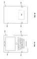
Figure 1A is a front view of a rechargeable medium for use with the present technology; -
Figure 1B is a back view of the rechargeable medium ofFigure 1A ; -
Figure 2 is a front view of the rechargeable medium ofFigures 1A and 1B and a charging cradle implementing the current technology; -
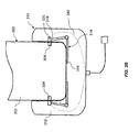
Figure 3A is a front view of the rechargeable medium ofFigures 1A and 1B being inserted into a charging cradle implementing an embodiment of the current technology, the charging circuit of the charging cradle being in a non-charging state; -
Figure 3B is a front view of the rechargeable medium ofFigures 1A and 1B being charged by the charging cradle ofFigure 3A when the charging circuit of the charging cradle is in a charging state; -
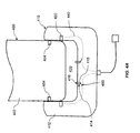
Figure 4A is a front view of the rechargeable medium ofFigures 1A and 1B being inserted into a charging cradle implementing another embodiment of the current technology, the charging circuit of the charging cradle being in a non-charging state; and -
Figure 4B is a front view of the rechargeable medium ofFigures 1A and 1B being charged by the charging cradle ofFigure 4A when the charging circuit of the charging cradle is in a charging state. - While the patent disclosure is described in conjunction with the specific embodiments, it will be understood that it is not intended to limit the patent disclosure to the described embodiments. On the contrary, it is intended to cover alternatives, modifications, and equivalents as may be included within the scope of the patent disclosure as defined by the appended claims. In the above description, numerous specific details are set forth in order to provide a thorough understanding of the present patent disclosure. The present patent disclosure may be practiced without some or all of these specific details.
- In this specification and the appended claims, the singular forms "a," "an," and "the" include plural references unless the context clearly dictates otherwise. Unless defined otherwise, all technical and scientific terms used herein have the same meaning as commonly understood to one of ordinary skill in the art to which this technology belongs.
- It will be further understood that the terms "comprises" or "comprising", or both when used in this specification, specify the presence of stated features, integers, steps, operations, elements, and/or components, but do not preclude the presence or addition of one or more other features, integers, steps, operations, elements, components, and/or groups thereof.
- The details and particulars of the technology will now be described below, by way of example, with reference to the attached drawings.
- Referring to
FIGs. 1A and 1B , arechargeable medium 100 with arechargeable battery 102 is illustrated. Therechargeable battery 102 may be encased in ahousing 104 of therechargeable medium 100. While therechargeable medium 100 is depicted as having generally the proportions of a smart phone, it may be other portable devices including laptops, tablets, personal entertainment devices or other portable devices with a battery. Moreover, therechargeable medium 100 may simply be the battery of the portable device. By recharging only the battery of the portable device, advantageously, the user of the portable device would be able to continue using the device with a spare battery. - The
rechargeable medium 100 has a chargingcontact 106 through which therechargeable medium 100 may be recharged. While therechargeable medium 100 is depicted as having twocharging contacts 106, it is understood that therechargeable medium 100 may have one or morecharging contacts 106. - Turning to
FIG. 2 , therechargeable medium 100 may be recharged using acharging cradle 108 having a cradling-body 110. While thecharging cradle 108 is depicted as having generally the proportions of a cradle for a smartphone or a portable entertainment device, it is understood that the cradle may be other charging devices such as a docking station for a notebook or a tablet. The cradling-body 110 has areceiving area 112 shaped to receive therechargeable medium 100. The cradling-body 110 further has a chargingcontact 114 for charging therechargeable medium 100. While the chargingcontact 114 is depicted as having twocharging contacts 114, it is understood that the cradling-body 110 may have one or morecharging contacts 114. Thecharging contact 114 is electrically coupled to thecharging circuit 116, which may be coupled to apower source 118. To prevent short-circuiting of thecharging circuit 116 while therechargeable medium 100 is being inserted into thereceiving area 112 of the cradling-body 110, a switch is included in the cradling-body 110 (specific implementation shown inFIGs. 3 and4 and discussed below). The switch interacts with therechargeable medium 100 to place thecharging circuit 116 in either a charging state or a non-charging state. - Thus, when the
rechargeable medium 100 is fully inserted into thereceiving area 112 of the cradling-body 110 such that thecharging contact 106 of therechargeable medium 100 is aligned with thecharging contact 114 of the cradling-body 110, the switch is positioned to place thecharging circuit 116 in the charging state. Otherwise, the switch is positioned to place thecharging circuit 116 in the non-charging state. - The specific implementations of the
charging cradle 108 will now be described below. - In
FIGs. 3A and3B , there is shown an implementation of the present technology. In this implementation, thecharging cradle 310 has a cradling-body 312 with a switch in the form of anactuator 314 that is pivotally mounted to the cradling-body 312. While inFIGs 3A and3B , thecharging cradle 310 is depicted with twoactuators 314, it is understood that thecharging cradle 310 may have one ormore actuators 314. - The
actuator 314 has afirst end 316 and asecond end 318. Thefirst end 316 is positioned in thereceiving area 330 to interact with therechargeable medium 300 and thesecond end 318 of theactuator 314 is coupled to themovable charging contact 320. As shown inFIGs. 3A and3B , thecharging contact 320 is movable to mate with thecharging contact 304 of therechargeable medium 300. InFIG. 3B , the chargingcontact 320 of the chargingcradle 310 is electrically coupled to thecharging contact 304 of therechargeable medium 300. When therechargeable medium 300 is not fully inserted into the receiving area 330 (or therechargeable medium 300 is not present), the chargingcontact 320 is moved by theactuator 314 to electrically decouple itself from the chargingcontact 304 of therechargeable medium 304, as shown inFIG. 3A . - Thus, the state of the charging
circuit 340 is determined by the position of theactuator 314, which is influenced by therechargeable medium 300. InFIG. 3A , where therechargeable medium 300 is not fully inserted into the receiving area 330 (or therechargeable medium 300 is not present), theactuator 314 is biased such that thesecond end 318 of the actuator 314 places the chargingcontact 320 of the chargingcradle 310 in the non-charging state. In this implementation, the non-charging state is created by moving the chargingcontact 320 inside the cradle-body 312. In this position, even if thehousing 302 of therechargeable medium 300 is a conductive material, thehousing 302 cannot short-circuit the chargingcircuit 340. - When the
rechargeable medium 300 is fully inserted into the receivingarea 330, as shown inFIG. 3B , therechargeable medium 300 interacts with thefirst end 316 of theactuator 314. In this particular implementation, as the chargingcontact 304 of therechargeable medium 300 aligns with the chargingcontact 320 of the chargingcradle 310, therechargeable medium 300 urges thefirst end 316 of theactuator 314. Because theactuator 314 is pivotally mounted to thecradling body 312, the movement of thefirst end 314 causes thesecond end 318 of theactuator 314 to move toward and protrude out into the receivingarea 330. When therechargeable medium 300 is fully inserted into the receivingarea 330, thesecond end 318 of theactuator 314, along with the chargingcontact 320, is positioned such that the chargingcontact 320 of the chargingcradle 310 is electrically coupled to thecharging contact 304 of therechargeable medium 300. Once electrically coupled, the chargingcircuit 340 begins to charge therechargeable medium 300. In effect, therechargeable medium 300 urges thesecond end 318 of theactuator 314, via thefirst end 316, to place the chargingcircuit 340 in the charging state. - Thus, through the interaction between the
rechargeable medium 300 and theactuator 314, the chargingcradle 310 is able to prevent short-circuiting of the chargingcircuit 340. Only when therechargeable medium 300 is fully inserted into the receivingarea 330, the chargingcontact 320 of the chargingcradle 310 would protrude out of the cradle-body 312 to electrically couple with the chargingcontact 304 of therechargeable medium 300. When therechargeable medium 300 is not fully inserted into the receivingarea 330 or when therechargeable medium 300 is not present, the chargingcontact 320 is retracted into the cradle-body 312 by theactuator 314. As a result, short-circuiting of the chargingcircuit 340 is prevented. - A further implementation of the present technology is shown in
FIGs. 4A and4B . The chargingcradle 410 has a cradling-body 412 with a fixedcharging contact 420. The fixedcharging contact 420 protrude into the receivingarea 430 such that when therechargeable medium 400 is fully inserted into the receivingarea 430, as shown inFIG. 4B , the fixedcharging contact 420 is able to electrically couple with the chargingcontact 404 of therechargeable medium 400. - The charging
cradle 410 further includes a switch in the form of anactuator 414. Theactuator 414 has afirst end 416 and asecond end 418. Thefirst end 416 is positioned in the receivingarea 430 to interact with therechargeable medium 400. Thesecond end 418 of theactuator 414 is positioned such that theelectrical switch 450 is openable and closeable by thesecond end 418. Theelectrical switch 450, in conjunction with theactuator 414, places the charging circuit in a charging state or a non-charging state. While inFIGs. 4A and4B , the chargingcradle 410 is depicted as having twoactuators 414 and two correspondingelectrical switches 450, one ormore actuators 414 andelectrical switches 450 may be included in the chargingcradle 410. - When the
rechargeable medium 400 is not fully inserted into the receivingarea 430, as shown inFIG. 4A , theactuator 414 is biased to place theelectrical switch 450 in the electrically open position. In this position, the chargingcircuit 440 is in a non-charging state. Thus, even if thehousing 402 is a conductive material, the chargingcircuit 440 is prevented from being short-circuited. By contrast, without theactuator 414 and theelectrical switch 450, the conductive material of thehousing 402 would complete thecharging circuit 440 without a load (i.e. battery) and thus, the chargingcircuit 440 would be short-circuited. - As the
rechargeable medium 400 is slid into the receivingarea 430, the rechargeable medium 400 starts to urge thefirst end 416 of theactuator 414. The movement of thefirst end 416 translates into a movement of thesecond end 418, which is positioned to close or open theelectrical switch 450. When therechargeable medium 400 is fully inserted into the receivingarea 430, theactuator 414 forces theelectrical switch 450 closed. Since, at this position, the chargingcontact 404 of therechargeable medium 400 is electrically coupled to thecharging contact 420 of the chargingcradle 410, as shown inFIG. 4B , the chargingcircuit 440 starts to conduct electricity and in turn, charges therechargeable medium 400. In effect, therechargeable medium 400 urges thesecond end 418 of theactuator 414, via thefirst end 416, to place the chargingcircuit 440 in the charging state. - While the charging cradle has been described in terms of specific implementations and configurations, further modifications, variations, modifications and refinements may be made without departing from the inventive concepts presented herein. For example, while the switch has been described with respect to a mechanical and an electro-mechanical implementation, it will be appreciated that other switches, such as a magnetic switch, that interact with the rechargeable medium may be possible without departing from the scope of the invention as defined in the claims. In an implementation using a magnetic switch, when the rechargeable medium is fully inserted into the receiving area of the charging cradle, the magnetic switch would be induced by the rechargeable medium to place the charging circuit in the charging state. Otherwise, the charging circuit would be in the non-charging state. The scope of the exclusive right sought by the Applicant(s) is therefore intended to be limited solely by the appended claims.
Claims (15)
- A charging cradle (108, 310, 410) for a rechargeable medium (100, 300, 400) having a charging contact (106, 304, 404), the charging cradle comprising:a cradling-body (110, 312, 412) comprising:a receiving area (112, 330, 430) shaped to receive the rechargeable medium;a charging circuit (116, 340, 440) having a charging and a non-charging state;a charging contact (114, 320, 420) electrically coupled to the charging circuit and positioned to be alignable with the charging contact of the rechargeable medium; anda switch (314, 414) coupled to the cradling-body for interacting with the rechargeable medium to place the charging circuit in the charging state or the non-charging state;wherein when the rechargeable medium is fully inserted into the receiving area such that the charging contact of the rechargeable medium is aligned with the charging contact of the cradling-body, the rechargeable medium, via the switch, places the charging circuit in the charging state, and when the rechargeable medium is not fully inserted, the switch places the charging circuit in the non-charging state to prevent short-circuiting of the charging circuit.
- The charging cradle according to claim 1, wherein the switch is an actuator having a first end and a second end, the first end being positioned in the receiving area to interact with the rechargeable medium such that when the rechargeable medium is fully inserted into the receiving area, the rechargeable medium urges the second end of the actuator, via the first end of the actuator, to place the charging circuit in the charging state.
- The charging cradle according to claim 2, wherein the actuator is pivotally coupled to the cradling-body and the second end of the actuator is coupled to the charging contact of the cradling-body.
- The charging cradle according to claim 3, wherein the charging contact of the cradling-body is movable between a first position and a second position by the actuator, the second end of the actuator moving the charging contact of the cradling-body to the first position to place the charging circuit in the charging state and moving the charging contact of the cradling-body to the second position to place the charging circuit in the non-charging state.
- The charging cradle according to claim 4, wherein at the first position of the charging contact of the cradling-body, the charging contact of the cradling-body is electrically coupled to the charging contact of the rechargeable medium, and at the second position of the charging contact of the cradling-body, the charging contact of the cradling-body is electrically decoupled from the charging contact of the rechargeable medium.
- The charging cradle according to claim 2, the charging circuit further comprising an electrical switch, the electrical switch closeable and openable by the second end of the actuator such that the electrical switch is closed when the charging circuit is in the charging state, and the electrical switch is open when the charging circuit is in the non-charging state.
- The charging cradle according to any one of claim 1-6, wherein the rechargeable medium is a mobile electronic device.
- The charging cradle according to any one of claim 1-6, wherein the rechargeable medium is a battery.
- The charging cradle according to claim 1, wherein the switch is a magnetic switch.
- A charging cradle (310) for a rechargeable medium (300) with a charging contact (304), the charging cradle having a cradling-body (312) with a receiving area (330) shaped to receive the rechargeable medium, the charging cradle comprising:a charging circuit (340) having a charging state and a non-charging state;an actuator (314) pivotally mounted to the cradling-body, the actuator having a first end (316) and a second end (318) with the first end being positioned in the receiving area for interacting with the rechargeable medium; anda charging contact (320) electrically coupled to the charging circuit and coupled to the second end of the actuator;wherein, when the rechargeable medium is fully inserted into the receiving area such that the charging contact of the rechargeable medium aligns with the charging contact of the charging cradle, the rechargeable medium urges the second end of the actuator, via the first end of the actuator, to place the charging circuit in the charging state, and when the rechargeable medium is not fully inserted, the actuator places the charging circuit in the non-charging state to prevent short-circuiting of the charging circuit.
- The charging cradle according to claim 10, wherein the charging contact is movable between a first position, where the charging contact of the charging cradle is electrically coupled to the charging contact of the rechargeable medium, and a second position, where the charging contact of the charging cradle is electrically decoupled to the charging contact of the rechargeable medium, the first position being associated with the charging state and the second position being associated with the non-charging state.
- The charging cradle according to claim 10 or 11, wherein the rechargeable medium is a mobile electronic device.
- The charging cradle according to claim 10 or 11, wherein the rechargeable medium is a battery.
- A charging cradle (410) for a rechargeable medium (400) with a charging contact (404), the charging cradle having a cradling-body (412) with a receiving area (430) shaped to receive the rechargeable medium, the charging cradle comprising:a charging circuit (440) having a charging and a non-charging state, the charging circuit comprising an electrical switch (450);a charging contact (420) electrically coupled to the charging circuit and coupled to the charging cradle and positioned to protrude into the receiving area; andan actuator (414) coupled to the cradling-body, the actuator having a first end (416) and a second end (418), the first end of the actuator positioned in the receiving area and the second end of the actuator positioned such that the electrical switch is closeable and openable by the second end of the actuator;wherein, when the rechargeable medium is fully inserted into the receiving area such that the charging contact of the rechargeable medium aligns with the charging contact of the charging cradle, the rechargeable medium urges the second end of the actuator, via the first end of the actuator, to close the electrical switch to place the charging circuit in the charging state, and when the rechargeable medium is not fully inserted, the actuator places the charging circuit in the non-charging state, by opening the electrical switch, to prevent short-circuiting of the charging circuit.
- The charging cradle according to claim 14, wherein the rechargeable medium is a mobile electronic device or a battery.
Priority Applications (2)
| Application Number | Priority Date | Filing Date | Title |
|---|---|---|---|
| EP10193026A EP2458706B1 (en) | 2010-11-29 | 2010-11-29 | Charging cradle |
| CA2759509A CA2759509C (en) | 2010-11-29 | 2011-11-29 | Charging cradle |
Applications Claiming Priority (1)
| Application Number | Priority Date | Filing Date | Title |
|---|---|---|---|
| EP10193026A EP2458706B1 (en) | 2010-11-29 | 2010-11-29 | Charging cradle |
Publications (2)
| Publication Number | Publication Date |
|---|---|
| EP2458706A1 true EP2458706A1 (en) | 2012-05-30 |
| EP2458706B1 EP2458706B1 (en) | 2013-03-27 |
Family
ID=43901038
Family Applications (1)
| Application Number | Title | Priority Date | Filing Date |
|---|---|---|---|
| EP10193026A Active EP2458706B1 (en) | 2010-11-29 | 2010-11-29 | Charging cradle |
Country Status (2)
| Country | Link |
|---|---|
| EP (1) | EP2458706B1 (en) |
| CA (1) | CA2759509C (en) |
Citations (6)
| Publication number | Priority date | Publication date | Assignee | Title |
|---|---|---|---|---|
| US20050225294A1 (en) * | 2004-04-08 | 2005-10-13 | Bozzone Stephen O | Method and apparatus for indication of a charging condition |
| DE102004044089A1 (en) * | 2004-09-09 | 2006-04-06 | Braun Gmbh | Charging unit, for small electrical appliances, has a holder where the appliance is against contacts during charging and abruptly pushed clear by a spring when battery charging is complete |
| EP1998423A2 (en) * | 2007-05-28 | 2008-12-03 | Sony Ericsson Mobile Communications Japan, Inc. | Contactless power transferring apparatus |
| EP2073338A1 (en) * | 2007-12-19 | 2009-06-24 | Deutsche Telekom AG | Charge device for cordless telephones |
| EP2112740A2 (en) * | 2008-04-22 | 2009-10-28 | Strax UK Ltd. | Charger for portable devices |
| US20100173674A1 (en) * | 2007-12-14 | 2010-07-08 | Fujitsu Limited | Holding base and information processing system |
-
2010
- 2010-11-29 EP EP10193026A patent/EP2458706B1/en active Active
-
2011
- 2011-11-29 CA CA2759509A patent/CA2759509C/en active Active
Patent Citations (6)
| Publication number | Priority date | Publication date | Assignee | Title |
|---|---|---|---|---|
| US20050225294A1 (en) * | 2004-04-08 | 2005-10-13 | Bozzone Stephen O | Method and apparatus for indication of a charging condition |
| DE102004044089A1 (en) * | 2004-09-09 | 2006-04-06 | Braun Gmbh | Charging unit, for small electrical appliances, has a holder where the appliance is against contacts during charging and abruptly pushed clear by a spring when battery charging is complete |
| EP1998423A2 (en) * | 2007-05-28 | 2008-12-03 | Sony Ericsson Mobile Communications Japan, Inc. | Contactless power transferring apparatus |
| US20100173674A1 (en) * | 2007-12-14 | 2010-07-08 | Fujitsu Limited | Holding base and information processing system |
| EP2073338A1 (en) * | 2007-12-19 | 2009-06-24 | Deutsche Telekom AG | Charge device for cordless telephones |
| EP2112740A2 (en) * | 2008-04-22 | 2009-10-28 | Strax UK Ltd. | Charger for portable devices |
Also Published As
| Publication number | Publication date |
|---|---|
| EP2458706B1 (en) | 2013-03-27 |
| CA2759509C (en) | 2016-11-01 |
| CA2759509A1 (en) | 2012-05-29 |
Similar Documents
| Publication | Publication Date | Title |
|---|---|---|
| US8610403B2 (en) | Charging cradle | |
| EP2388886B1 (en) | Wireless charging jacket combined with a battery and wireless charging system thereof | |
| EP2830188B1 (en) | Wireless charger equipped with auxiliary power supply and auxiliary power device | |
| EP2070176B1 (en) | Battery charger | |
| CN107863800B (en) | wireless rechargeable battery | |
| JP5813135B2 (en) | Mobile charger | |
| EP2782207A1 (en) | Protecting device for electronic device | |
| CN108701878B (en) | Auxiliary battery capable of transmitting and receiving wireless power | |
| KR101767622B1 (en) | Exterior case of portable electronic device having circuit for contact-less charge | |
| EP1589631A3 (en) | Portable electronic device and mobile communication terminal | |
| CN212936147U (en) | Earphone charging device and Bluetooth earphone | |
| US8253381B2 (en) | Charging device | |
| CA2759509C (en) | Charging cradle | |
| KR20150007708A (en) | Wireless charger | |
| KR200478882Y1 (en) | Portable power pack | |
| GB2386267A (en) | Holster with battery for portable equipment | |
| US7910235B2 (en) | Self-charging lithium battery | |
| US20040227850A1 (en) | Digital camera for use with mobile phone | |
| JP5749533B2 (en) | Electronics | |
| CN201655921U (en) | Voltage-selectable charger | |
| KR20160046111A (en) | Device Having Improved Charging Convenience and Employed with Adaptor | |
| CN212366885U (en) | Novel treasured that charges with mouthful protection charges | |
| CN202524123U (en) | charger | |
| KR200446304Y1 (en) | Solar charger capable of charging and discharging to USS port | |
| CN203339733U (en) | Wireless mobile power supply device |
Legal Events
| Date | Code | Title | Description |
|---|---|---|---|
| GRAP | Despatch of communication of intention to grant a patent |
Free format text: ORIGINAL CODE: EPIDOSNIGR1 |
|
| PUAI | Public reference made under article 153(3) epc to a published international application that has entered the european phase |
Free format text: ORIGINAL CODE: 0009012 |
|
| 17P | Request for examination filed |
Effective date: 20101129 |
|
| AK | Designated contracting states |
Kind code of ref document: A1 Designated state(s): AL AT BE BG CH CY CZ DE DK EE ES FI FR GB GR HR HU IE IS IT LI LT LU LV MC MK MT NL NO PL PT RO RS SE SI SK SM TR |
|
| AX | Request for extension of the european patent |
Extension state: BA ME |
|
| GRAS | Grant fee paid |
Free format text: ORIGINAL CODE: EPIDOSNIGR3 |
|
| GRAA | (expected) grant |
Free format text: ORIGINAL CODE: 0009210 |
|
| AK | Designated contracting states |
Kind code of ref document: B1 Designated state(s): AL AT BE BG CH CY CZ DE DK EE ES FI FR GB GR HR HU IE IS IT LI LT LU LV MC MK MT NL NO PL PT RO RS SE SI SK SM TR |
|
| REG | Reference to a national code |
Ref country code: GB Ref legal event code: FG4D |
|
| REG | Reference to a national code |
Ref country code: CH Ref legal event code: EP |
|
| REG | Reference to a national code |
Ref country code: AT Ref legal event code: REF Ref document number: 603938 Country of ref document: AT Kind code of ref document: T Effective date: 20130415 |
|
| REG | Reference to a national code |
Ref country code: IE Ref legal event code: FG4D |
|
| REG | Reference to a national code |
Ref country code: DE Ref legal event code: R096 Ref document number: 602010005769 Country of ref document: DE Effective date: 20130529 |
|
| PG25 | Lapsed in a contracting state [announced via postgrant information from national office to epo] |
Ref country code: NO Free format text: LAPSE BECAUSE OF FAILURE TO SUBMIT A TRANSLATION OF THE DESCRIPTION OR TO PAY THE FEE WITHIN THE PRESCRIBED TIME-LIMIT Effective date: 20130627 Ref country code: SE Free format text: LAPSE BECAUSE OF FAILURE TO SUBMIT A TRANSLATION OF THE DESCRIPTION OR TO PAY THE FEE WITHIN THE PRESCRIBED TIME-LIMIT Effective date: 20130327 Ref country code: BG Free format text: LAPSE BECAUSE OF FAILURE TO SUBMIT A TRANSLATION OF THE DESCRIPTION OR TO PAY THE FEE WITHIN THE PRESCRIBED TIME-LIMIT Effective date: 20130627 Ref country code: LT Free format text: LAPSE BECAUSE OF FAILURE TO SUBMIT A TRANSLATION OF THE DESCRIPTION OR TO PAY THE FEE WITHIN THE PRESCRIBED TIME-LIMIT Effective date: 20130327 |
|
| REG | Reference to a national code |
Ref country code: CH Ref legal event code: PFA Owner name: BLACKBERRY LIMITED, CA Free format text: FORMER OWNER: RESEARCH IN MOTION LIMITED, CA Ref country code: AT Ref legal event code: MK05 Ref document number: 603938 Country of ref document: AT Kind code of ref document: T Effective date: 20130327 |
|
| REG | Reference to a national code |
Ref country code: LT Ref legal event code: MG4D |
|
| REG | Reference to a national code |
Ref country code: NL Ref legal event code: T3 |
|
| PG25 | Lapsed in a contracting state [announced via postgrant information from national office to epo] |
Ref country code: LV Free format text: LAPSE BECAUSE OF FAILURE TO SUBMIT A TRANSLATION OF THE DESCRIPTION OR TO PAY THE FEE WITHIN THE PRESCRIBED TIME-LIMIT Effective date: 20130327 Ref country code: GR Free format text: LAPSE BECAUSE OF FAILURE TO SUBMIT A TRANSLATION OF THE DESCRIPTION OR TO PAY THE FEE WITHIN THE PRESCRIBED TIME-LIMIT Effective date: 20130628 Ref country code: FI Free format text: LAPSE BECAUSE OF FAILURE TO SUBMIT A TRANSLATION OF THE DESCRIPTION OR TO PAY THE FEE WITHIN THE PRESCRIBED TIME-LIMIT Effective date: 20130327 Ref country code: SI Free format text: LAPSE BECAUSE OF FAILURE TO SUBMIT A TRANSLATION OF THE DESCRIPTION OR TO PAY THE FEE WITHIN THE PRESCRIBED TIME-LIMIT Effective date: 20130327 |
|
| RAP2 | Party data changed (patent owner data changed or rights of a patent transferred) |
Owner name: BLACKBERRY LIMITED |
|
| PG25 | Lapsed in a contracting state [announced via postgrant information from national office to epo] |
Ref country code: BE Free format text: LAPSE BECAUSE OF FAILURE TO SUBMIT A TRANSLATION OF THE DESCRIPTION OR TO PAY THE FEE WITHIN THE PRESCRIBED TIME-LIMIT Effective date: 20130327 Ref country code: HR Free format text: LAPSE BECAUSE OF FAILURE TO SUBMIT A TRANSLATION OF THE DESCRIPTION OR TO PAY THE FEE WITHIN THE PRESCRIBED TIME-LIMIT Effective date: 20130327 |
|
| PG25 | Lapsed in a contracting state [announced via postgrant information from national office to epo] |
Ref country code: PT Free format text: LAPSE BECAUSE OF FAILURE TO SUBMIT A TRANSLATION OF THE DESCRIPTION OR TO PAY THE FEE WITHIN THE PRESCRIBED TIME-LIMIT Effective date: 20130729 Ref country code: CZ Free format text: LAPSE BECAUSE OF FAILURE TO SUBMIT A TRANSLATION OF THE DESCRIPTION OR TO PAY THE FEE WITHIN THE PRESCRIBED TIME-LIMIT Effective date: 20130327 Ref country code: SK Free format text: LAPSE BECAUSE OF FAILURE TO SUBMIT A TRANSLATION OF THE DESCRIPTION OR TO PAY THE FEE WITHIN THE PRESCRIBED TIME-LIMIT Effective date: 20130327 Ref country code: EE Free format text: LAPSE BECAUSE OF FAILURE TO SUBMIT A TRANSLATION OF THE DESCRIPTION OR TO PAY THE FEE WITHIN THE PRESCRIBED TIME-LIMIT Effective date: 20130327 Ref country code: RO Free format text: LAPSE BECAUSE OF FAILURE TO SUBMIT A TRANSLATION OF THE DESCRIPTION OR TO PAY THE FEE WITHIN THE PRESCRIBED TIME-LIMIT Effective date: 20130327 Ref country code: IS Free format text: LAPSE BECAUSE OF FAILURE TO SUBMIT A TRANSLATION OF THE DESCRIPTION OR TO PAY THE FEE WITHIN THE PRESCRIBED TIME-LIMIT Effective date: 20130727 Ref country code: AT Free format text: LAPSE BECAUSE OF FAILURE TO SUBMIT A TRANSLATION OF THE DESCRIPTION OR TO PAY THE FEE WITHIN THE PRESCRIBED TIME-LIMIT Effective date: 20130327 Ref country code: ES Free format text: LAPSE BECAUSE OF FAILURE TO SUBMIT A TRANSLATION OF THE DESCRIPTION OR TO PAY THE FEE WITHIN THE PRESCRIBED TIME-LIMIT Effective date: 20130708 |
|
| REG | Reference to a national code |
Ref country code: CH Ref legal event code: PCOW Free format text: NEW ADDRESS: 2200 UNIVERSITY AVENUE EAST, WATERLOO, ON N2K 0A7 (CA) |
|
| RAP2 | Party data changed (patent owner data changed or rights of a patent transferred) |
Owner name: BLACKBERRY LIMITED |
|
| PG25 | Lapsed in a contracting state [announced via postgrant information from national office to epo] |
Ref country code: PL Free format text: LAPSE BECAUSE OF FAILURE TO SUBMIT A TRANSLATION OF THE DESCRIPTION OR TO PAY THE FEE WITHIN THE PRESCRIBED TIME-LIMIT Effective date: 20130327 Ref country code: CY Free format text: LAPSE BECAUSE OF FAILURE TO SUBMIT A TRANSLATION OF THE DESCRIPTION OR TO PAY THE FEE WITHIN THE PRESCRIBED TIME-LIMIT Effective date: 20130327 |
|
| PG25 | Lapsed in a contracting state [announced via postgrant information from national office to epo] |
Ref country code: DK Free format text: LAPSE BECAUSE OF FAILURE TO SUBMIT A TRANSLATION OF THE DESCRIPTION OR TO PAY THE FEE WITHIN THE PRESCRIBED TIME-LIMIT Effective date: 20130327 |
|
| PLBE | No opposition filed within time limit |
Free format text: ORIGINAL CODE: 0009261 |
|
| STAA | Information on the status of an ep patent application or granted ep patent |
Free format text: STATUS: NO OPPOSITION FILED WITHIN TIME LIMIT |
|
| PG25 | Lapsed in a contracting state [announced via postgrant information from national office to epo] |
Ref country code: IT Free format text: LAPSE BECAUSE OF FAILURE TO SUBMIT A TRANSLATION OF THE DESCRIPTION OR TO PAY THE FEE WITHIN THE PRESCRIBED TIME-LIMIT Effective date: 20130327 |
|
| 26N | No opposition filed |
Effective date: 20140103 |
|
| REG | Reference to a national code |
Ref country code: DE Ref legal event code: R097 Ref document number: 602010005769 Country of ref document: DE Effective date: 20140103 |
|
| PG25 | Lapsed in a contracting state [announced via postgrant information from national office to epo] |
Ref country code: MC Free format text: LAPSE BECAUSE OF FAILURE TO SUBMIT A TRANSLATION OF THE DESCRIPTION OR TO PAY THE FEE WITHIN THE PRESCRIBED TIME-LIMIT Effective date: 20130327 |
|
| REG | Reference to a national code |
Ref country code: IE Ref legal event code: MM4A |
|
| REG | Reference to a national code |
Ref country code: DE Ref legal event code: R082 Ref document number: 602010005769 Country of ref document: DE Representative=s name: MERH-IP MATIAS ERNY REICHL HOFFMANN, DE |
|
| PG25 | Lapsed in a contracting state [announced via postgrant information from national office to epo] |
Ref country code: IE Free format text: LAPSE BECAUSE OF NON-PAYMENT OF DUE FEES Effective date: 20131129 |
|
| REG | Reference to a national code |
Ref country code: DE Ref legal event code: R081 Ref document number: 602010005769 Country of ref document: DE Owner name: BLACKBERRY LIMITED, WATERLOO, CA Free format text: FORMER OWNER: RESEARCH IN MOTION LIMITED, WATERLOO, ONTARIO, CA Effective date: 20140926 Ref country code: DE Ref legal event code: R082 Ref document number: 602010005769 Country of ref document: DE Representative=s name: MERH-IP MATIAS ERNY REICHL HOFFMANN, DE Effective date: 20140926 Ref country code: DE Ref legal event code: R082 Ref document number: 602010005769 Country of ref document: DE Representative=s name: MERH-IP MATIAS ERNY REICHL HOFFMANN PATENTANWA, DE Effective date: 20140926 |
|
| PG25 | Lapsed in a contracting state [announced via postgrant information from national office to epo] |
Ref country code: SM Free format text: LAPSE BECAUSE OF FAILURE TO SUBMIT A TRANSLATION OF THE DESCRIPTION OR TO PAY THE FEE WITHIN THE PRESCRIBED TIME-LIMIT Effective date: 20130327 |
|
| PG25 | Lapsed in a contracting state [announced via postgrant information from national office to epo] |
Ref country code: TR Free format text: LAPSE BECAUSE OF FAILURE TO SUBMIT A TRANSLATION OF THE DESCRIPTION OR TO PAY THE FEE WITHIN THE PRESCRIBED TIME-LIMIT Effective date: 20130327 |
|
| REG | Reference to a national code |
Ref country code: CH Ref legal event code: PL |
|
| PG25 | Lapsed in a contracting state [announced via postgrant information from national office to epo] |
Ref country code: LI Free format text: LAPSE BECAUSE OF NON-PAYMENT OF DUE FEES Effective date: 20141130 Ref country code: RS Free format text: LAPSE BECAUSE OF FAILURE TO SUBMIT A TRANSLATION OF THE DESCRIPTION OR TO PAY THE FEE WITHIN THE PRESCRIBED TIME-LIMIT Effective date: 20130627 Ref country code: LU Free format text: LAPSE BECAUSE OF NON-PAYMENT OF DUE FEES Effective date: 20131129 Ref country code: HU Free format text: LAPSE BECAUSE OF FAILURE TO SUBMIT A TRANSLATION OF THE DESCRIPTION OR TO PAY THE FEE WITHIN THE PRESCRIBED TIME-LIMIT; INVALID AB INITIO Effective date: 20101129 Ref country code: CH Free format text: LAPSE BECAUSE OF NON-PAYMENT OF DUE FEES Effective date: 20141130 Ref country code: MK Free format text: LAPSE BECAUSE OF FAILURE TO SUBMIT A TRANSLATION OF THE DESCRIPTION OR TO PAY THE FEE WITHIN THE PRESCRIBED TIME-LIMIT Effective date: 20130327 |
|
| PG25 | Lapsed in a contracting state [announced via postgrant information from national office to epo] |
Ref country code: MT Free format text: LAPSE BECAUSE OF FAILURE TO SUBMIT A TRANSLATION OF THE DESCRIPTION OR TO PAY THE FEE WITHIN THE PRESCRIBED TIME-LIMIT Effective date: 20130327 |
|
| REG | Reference to a national code |
Ref country code: FR Ref legal event code: PLFP Year of fee payment: 6 |
|
| REG | Reference to a national code |
Ref country code: FR Ref legal event code: PLFP Year of fee payment: 7 |
|
| REG | Reference to a national code |
Ref country code: FR Ref legal event code: PLFP Year of fee payment: 8 |
|
| PG25 | Lapsed in a contracting state [announced via postgrant information from national office to epo] |
Ref country code: AL Free format text: LAPSE BECAUSE OF FAILURE TO SUBMIT A TRANSLATION OF THE DESCRIPTION OR TO PAY THE FEE WITHIN THE PRESCRIBED TIME-LIMIT Effective date: 20130327 |
|
| REG | Reference to a national code |
Ref country code: DE Ref legal event code: R082 Ref document number: 602010005769 Country of ref document: DE Ref country code: DE Ref legal event code: R081 Ref document number: 602010005769 Country of ref document: DE Owner name: MALIKIE INNOVATIONS LTD., IE Free format text: FORMER OWNER: BLACKBERRY LIMITED, WATERLOO, ONTARIO, CA |
|
| PGFP | Annual fee paid to national office [announced via postgrant information from national office to epo] |
Ref country code: NL Payment date: 20251124 Year of fee payment: 16 |
|
| PGFP | Annual fee paid to national office [announced via postgrant information from national office to epo] |
Ref country code: DE Payment date: 20251126 Year of fee payment: 16 |
|
| PGFP | Annual fee paid to national office [announced via postgrant information from national office to epo] |
Ref country code: GB Payment date: 20251125 Year of fee payment: 16 |
|
| PGFP | Annual fee paid to national office [announced via postgrant information from national office to epo] |
Ref country code: FR Payment date: 20251125 Year of fee payment: 16 |