EP2458699A1 - Cable arrangement and method - Google Patents
Cable arrangement and method Download PDFInfo
- Publication number
- EP2458699A1 EP2458699A1 EP10192686A EP10192686A EP2458699A1 EP 2458699 A1 EP2458699 A1 EP 2458699A1 EP 10192686 A EP10192686 A EP 10192686A EP 10192686 A EP10192686 A EP 10192686A EP 2458699 A1 EP2458699 A1 EP 2458699A1
- Authority
- EP
- European Patent Office
- Prior art keywords
- cable holder
- cables
- image acquisition
- acquisition device
- processing unit
- Prior art date
- Legal status (The legal status is an assumption and is not a legal conclusion. Google has not performed a legal analysis and makes no representation as to the accuracy of the status listed.)
- Withdrawn
Links
- 238000000034 method Methods 0.000 title claims description 7
- 239000002184 metal Substances 0.000 claims description 5
- 239000004033 plastic Substances 0.000 claims description 5
- 229920001296 polysiloxane Polymers 0.000 claims description 5
- 238000004804 winding Methods 0.000 claims description 5
- 239000000463 material Substances 0.000 claims description 3
- 230000011664 signaling Effects 0.000 description 3
- 238000001125 extrusion Methods 0.000 description 2
- 238000004519 manufacturing process Methods 0.000 description 2
- 238000000465 moulding Methods 0.000 description 2
- 238000005452 bending Methods 0.000 description 1
Images

Classifications
-
- H—ELECTRICITY
- H02—GENERATION; CONVERSION OR DISTRIBUTION OF ELECTRIC POWER
- H02G—INSTALLATION OF ELECTRIC CABLES OR LINES, OR OF COMBINED OPTICAL AND ELECTRIC CABLES OR LINES
- H02G11/00—Arrangements of electric cables or lines between relatively-movable parts
-
- H—ELECTRICITY
- H02—GENERATION; CONVERSION OR DISTRIBUTION OF ELECTRIC POWER
- H02G—INSTALLATION OF ELECTRIC CABLES OR LINES, OR OF COMBINED OPTICAL AND ELECTRIC CABLES OR LINES
- H02G3/00—Installations of electric cables or lines or protective tubing therefor in or on buildings, equivalent structures or vehicles
- H02G3/02—Details
- H02G3/04—Protective tubing or conduits, e.g. cable ladders or cable troughs
- H02G3/0462—Tubings, i.e. having a closed section
- H02G3/0481—Tubings, i.e. having a closed section with a circular cross-section
Definitions
- the present invention relates to an arrangement and to a method for assembling the arrangement.
- the arrangement comprises a plurality of cables, a cable holder for holding the plurality of cables, a turnable image acquisition device, and a processing unit, wherein the plurality of cables are arranged to connect the turnable image acquisition device and the processing unit.
- Network cameras usually have a bundle of thin signaling wires that connect the camera head and the Printed Circuit Board (PCB).
- the wires need to be long enough to ensure that the camera head can both pan and tilt the full specified distance. Still, the wires need to be as short as possible so that they do not take up more space than necessary in the small space available. Additionally, the wires need to be very flexible in all directions not to put on extra load on the pan and tilt motors. Furthermore, the signaling wires need to be gathered to ensure that they do not get entangled or get caught in other parts of the camera.
- a solution to this is to wrap the wires with tape.
- the tape wrapping makes the bundle of thin signaling wires stiff and thus reduces the ability of the camera to pan/tilt and puts unnecessarily large load on the pan/tilt motors.
- an objective of the invention is to solve or at least reduce one or several of the drawbacks discussed above.
- the above objective is achieved by the attached independent patent claims.
- the present invention is realized by an arrangement comprising a plurality of cables, a cable holder for holding the plurality of cables, a turnable image acquisition device, and a processing unit.
- the plurality of cables are arranged to connect the turnable image acquisition device and the processing unit.
- the cable holder is helical and the plurality of cables are loosely fitted in the cable holder.
- the cables are held in place by the cable holder and do not get entangled or get caught in other parts of the arrangement. Furthermore, the plurality of cables are able to move freely inside the cable holder and hence do not put on extra load on the pan and tilt motors.
- the cable holder may be pliant. This is advantageous in that that the cable holder easily bends and, hence, does not put on extra load on the pan and tilt motors.
- the cable holder may be a coil spring. This is advantageous in that the cable holder is very flexible in all directions since the cable holder easily bends at every winding.
- the cable holder may be made of a material chosen from the group of a metal, a plastic, a rubber, or a silicone.
- Metal is advantageous in that it is robust.
- Plastic is advantageous in that it is easy to manufacture through, e.g., moulding or extrusion.
- Rubber and silicone are advantageous in that they are highly flexible.
- the present invention is realized by a method for assembling an arrangement comprising a plurality of cables, a cable holder for holding the plurality of cables, a turnable image acquisition device, and a processing unit, wherein the cable holder is helical, and wherein the plurality of cables are loosely fitted in the cable holder.
- the method comprises: arranging the plurality of cables in the cable holder, connecting the turnable image acquisition device and the processing unit using the plurality of cables.
- the second aspect can be embodied in accordance with the first aspect. Furthermore, the advantages of the first aspect apply to the second aspect as well.
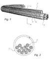
- Fig. 1 discloses an inventive cable holder 1 and a plurality of cables 2.
- the plurality of cables 2 are arranged to connect a turnable image acquisition device (not shown) and a processing unit (not shown).
- the cable holder 1 is helically shaped or wound and the plurality of cables 2 are loosely fitted in the cable holder 1.
- Fig. 2 is a cross-sectional view of the cable holder 1 and the plurality of cables 2 of Fig. 1 . It is clear, from both Figs. 1 and 2 , that the plurality of cables 2 are loosely fitted in the cable holder 1.
- the plurality of cables 2 are able to move freely inside the cable holder 1 and hence do not put on extra load on the pan and tilt motors.
- Fig. 3 schematically illustrates the inventive arrangement comprising the plurality of cables 2 arranged in the cable holder 1 and connecting a turnable image acquisition device 3 and a processing unit 4.
- the processing unit 4 can be any type of known processing unit, e.g., a PCB (Printed Circuit Board).
- the turnable image acquisition device 3 can, e.g., be a network camera that is arranged to pan and/or tilt.
- the turnable image acquisition device 3 can, e.g., be able to rotate more than 360 degrees.
- a length of the cable holder 1 is substantially equal to a length of the plurality of cables 2. It is realized that the cable holder 1 can be shorter than the plurality of cables 2.
- the arrangement comprises a plurality of cable holders 1.
- the cable holder 1 can enclose an entire length of the plurality of cables 2.
- the cable holder 1 can enclose a part of a length of the plurality of cables.
- a plurality of cable holders 1 can enclose a plurality of parts of the plurality of cables 2.
- the arrangement is assembled by arranging the plurality of cables 2 in the cable holder 1 and connecting the turnable image acquisition device 3 and the processing unit 4 using the plurality of cables 2.
- the plurality of cables 2 are held in place by the cable holder 1 and do not get entangled nor get caught in other parts of the arrangement.
- the image acquisition device 3 rotates, the plurality of cables 2 are able to move freely inside the cable holder 1.
- the cable holder 1 is pliant and bends easily.
- the arrangement has the advantage that no extra load is put on the motor causing the rotating motion.
- the cable holder 1 is a coil spring.
- the windings of the coil spring simplify the bending of the coil spring.
- the cable holder may 1 be made of a material chosen from the group of a metal, a plastic, a rubber, or a silicone.
- Metal is advantageous in that it is robust.
- Plastic is advantageous in that it is easy to manufacture through, e.g., moulding or extrusion.
- Rubber is advantageous in that it is highly flexible.
- Silicone is advantageous in that it is highly flexible.
- a length of the cable holder 1 may be in the range of 10-400 mm.
- a diameter of at least one of the plurality of cables 2 may be in the range of 0,1-2 mm.
- a distance between two adjacent windings 11 and 12 of the cable holder 1 may be in the range of 0,1-5 mm.
- a thickness of a winding 11 of the cable holder 1 may be in the range of 0,01-1 mm.
- the inventive cable holder 1 is particularly advantageous in arrangements comprising small turnable image acquisition devices 3 because such arrangements do not have space enough to incorporate large motors for providing rotation and/or tilt of the turnable image acquisition devices 3. Due to the required small size of the motors, the plurality of cables 2 and the cable holder 1 must not put on extra load on the motors and hence is the inventive arrangement particularly advantageous.
Landscapes
- Engineering & Computer Science (AREA)
- Architecture (AREA)
- Civil Engineering (AREA)
- Structural Engineering (AREA)
- Electric Cable Arrangement Between Relatively Moving Parts (AREA)
Abstract
The present invention relates to assembling an arrangement. The arrangement comprises a plurality of cables (2), a cable holder (1) for holding the plurality of cables (2), a turnable image acquisition device (3), and a processing unit (4), wherein the plurality of cables (2) are arranged to connect the turnable image acquisition device (3) and the processing unit (4), wherein the cable holder (2) is helical, and wherein the plurality of cables (2) are loosely fitted in the cable holder (1).
Description
- The present invention relates to an arrangement and to a method for assembling the arrangement. The arrangement comprises a plurality of cables, a cable holder for holding the plurality of cables, a turnable image acquisition device, and a processing unit, wherein the plurality of cables are arranged to connect the turnable image acquisition device and the processing unit.
- Network cameras usually have a bundle of thin signaling wires that connect the camera head and the Printed Circuit Board (PCB). The wires need to be long enough to ensure that the camera head can both pan and tilt the full specified distance. Still, the wires need to be as short as possible so that they do not take up more space than necessary in the small space available. Additionally, the wires need to be very flexible in all directions not to put on extra load on the pan and tilt motors. Furthermore, the signaling wires need to be gathered to ensure that they do not get entangled or get caught in other parts of the camera.
- A solution to this is to wrap the wires with tape. However, the tape wrapping makes the bundle of thin signaling wires stiff and thus reduces the ability of the camera to pan/tilt and puts unnecessarily large load on the pan/tilt motors.
- In view of the above, an objective of the invention is to solve or at least reduce one or several of the drawbacks discussed above. Generally, the above objective is achieved by the attached independent patent claims.
- According to a first aspect, the present invention is realized by an arrangement comprising a plurality of cables, a cable holder for holding the plurality of cables, a turnable image acquisition device, and a processing unit. The plurality of cables are arranged to connect the turnable image acquisition device and the processing unit. The cable holder is helical and the plurality of cables are loosely fitted in the cable holder.
- This is advantageous in that the cables are held in place by the cable holder and do not get entangled or get caught in other parts of the arrangement. Furthermore, the plurality of cables are able to move freely inside the cable holder and hence do not put on extra load on the pan and tilt motors.
- The cable holder may be pliant. This is advantageous in that that the cable holder easily bends and, hence, does not put on extra load on the pan and tilt motors.
- The cable holder may be a coil spring. This is advantageous in that the cable holder is very flexible in all directions since the cable holder easily bends at every winding.
- The cable holder may be made of a material chosen from the group of a metal, a plastic, a rubber, or a silicone. Metal is advantageous in that it is robust. Plastic is advantageous in that it is easy to manufacture through, e.g., moulding or extrusion. Rubber and silicone are advantageous in that they are highly flexible.
- According to a second aspect, the present invention is realized by a method for assembling an arrangement comprising a plurality of cables, a cable holder for holding the plurality of cables, a turnable image acquisition device, and a processing unit, wherein the cable holder is helical, and wherein the plurality of cables are loosely fitted in the cable holder. The method comprises: arranging the plurality of cables in the cable holder, connecting the turnable image acquisition device and the processing unit using the plurality of cables.
- It is to be noted that the second aspect can be embodied in accordance with the first aspect. Furthermore, the advantages of the first aspect apply to the second aspect as well.
- Other objectives, features and advantages of the present invention will appear from the following detailed disclosure, from the attached claims as well as from the drawings.
- Generally, all terms used in the claims are to be interpreted according to their ordinary meaning in the technical field, unless explicitly defined otherwise herein. All references to "a/an/the [element, device, component, means, step, etc]" are to be interpreted openly as referring to at least one instance of said element, device, component, means, step, etc., unless explicitly stated otherwise. The steps of any method disclosed herein do not have to be performed in the exact order disclosed, unless explicitly stated.
- Other features and advantages of the present invention will become apparent from the following detailed description of a presently preferred embodiment, with reference to the accompanying drawings, in which
-
Fig. 1 is a perspective view of a cable holder and a plurality of cables that are part of the inventive arrangement. -
Fig. 2 is a cross-sectional view of the cable holder and the plurality of cables ofFig. 1 . -
Fig. 3 is a schematic illustration of the inventive arrangement. - The present invention will now be described more fully hereinafter with reference to the accompanying drawings, in which certain embodiments of the invention are shown. This invention may, however, be embodied in many different forms and should not be construed as limited to the embodiments set forth herein; rather, these embodiments are provided by way of example so that this disclosure will be thorough and complete, and will fully convey the scope of the invention to those skilled in the art. Like numbers refer to like elements throughout.
-
Fig. 1 discloses aninventive cable holder 1 and a plurality ofcables 2. The plurality ofcables 2 are arranged to connect a turnable image acquisition device (not shown) and a processing unit (not shown). Thecable holder 1 is helically shaped or wound and the plurality ofcables 2 are loosely fitted in thecable holder 1.Fig. 2 is a cross-sectional view of thecable holder 1 and the plurality ofcables 2 ofFig. 1 . It is clear, from bothFigs. 1 and 2 , that the plurality ofcables 2 are loosely fitted in thecable holder 1. Thus the plurality ofcables 2 are able to move freely inside thecable holder 1 and hence do not put on extra load on the pan and tilt motors. -
Fig. 3 schematically illustrates the inventive arrangement comprising the plurality ofcables 2 arranged in thecable holder 1 and connecting a turnableimage acquisition device 3 and a processing unit 4. The processing unit 4 can be any type of known processing unit, e.g., a PCB (Printed Circuit Board). The turnableimage acquisition device 3 can, e.g., be a network camera that is arranged to pan and/or tilt. The turnableimage acquisition device 3 can, e.g., be able to rotate more than 360 degrees. - In
Fig. 3 , a length of thecable holder 1 is substantially equal to a length of the plurality ofcables 2. It is realized that thecable holder 1 can be shorter than the plurality ofcables 2. In some embodiments the arrangement comprises a plurality ofcable holders 1. Thecable holder 1 can enclose an entire length of the plurality ofcables 2. Alternatively, thecable holder 1 can enclose a part of a length of the plurality of cables. As a further alternative, a plurality ofcable holders 1 can enclose a plurality of parts of the plurality ofcables 2. - The arrangement is assembled by arranging the plurality of
cables 2 in thecable holder 1 and connecting the turnableimage acquisition device 3 and the processing unit 4 using the plurality ofcables 2. - The plurality of
cables 2 are held in place by thecable holder 1 and do not get entangled nor get caught in other parts of the arrangement. When theimage acquisition device 3 rotates, the plurality ofcables 2 are able to move freely inside thecable holder 1. Furthermore, thecable holder 1 is pliant and bends easily. Hence, the arrangement has the advantage that no extra load is put on the motor causing the rotating motion. - In one embodiment, illustrated in
Fig. 1 , thecable holder 1 is a coil spring. The windings of the coil spring simplify the bending of the coil spring. - The cable holder may 1 be made of a material chosen from the group of a metal, a plastic, a rubber, or a silicone. Metal is advantageous in that it is robust. Plastic is advantageous in that it is easy to manufacture through, e.g., moulding or extrusion. Rubber is advantageous in that it is highly flexible. Silicone is advantageous in that it is highly flexible.
- A length of the
cable holder 1 may be in the range of 10-400 mm. - A diameter of at least one of the plurality of
cables 2 may be in the range of 0,1-2 mm. - A distance between two
adjacent windings cable holder 1 may be in the range of 0,1-5 mm. - A thickness of a winding 11 of the
cable holder 1 may be in the range of 0,01-1 mm. - The ranges outlined above are suitable in arrangements comprising, e.g., small and/or compact network cameras.
- The
inventive cable holder 1 is particularly advantageous in arrangements comprising small turnableimage acquisition devices 3 because such arrangements do not have space enough to incorporate large motors for providing rotation and/or tilt of the turnableimage acquisition devices 3. Due to the required small size of the motors, the plurality ofcables 2 and thecable holder 1 must not put on extra load on the motors and hence is the inventive arrangement particularly advantageous.
Claims (8)
- Arrangement comprising a plurality of cables (2), a cable holder (1) for holding the plurality of cables (2), a turnable image acquisition device (3), and a processing unit (4), wherein the plurality of cables (2) are arranged to connect the turnable image acquisition device (3) and the processing unit (4), wherein the cable holder (1) is helical, and wherein the plurality of cables (2) are loosely fitted in the cable holder (1).
- Arrangement according to claim 1, wherein the cable holder (1) is pliant.
- Arrangement according to any of claims 1-2, wherein the cable holder (1) is a coil spring.
- Arrangement according to any of claims 1-3, wherein the cable holder (1) is made of a material chosen from the group of a metal, a plastic, a rubber, or a silicone.
- Arrangement according to any one of claims 1-4, wherein a length of the cable holder (1) is in the range of 10-400 mm.
- Arrangement according to any one of claims 1-5, wherein a diameter of at least one of the plurality of cables (2) is in the range of 0,1-2 mm.
- Arrangement according to any one of claims 1-6, wherein a distance between two adjacent windings (11, 12) of the cable holder (1), when the cable holder (1) is in an unbent state, is in the range of 0,1-5 mm.
- Method for assembling an arrangement comprising a plurality of cables (2), a cable holder (1) for holding the plurality of cables (2), a turnable image acquisition device (3), and a processing unit (4), wherein the cable holder (1) is helical, and wherein the plurality of cables (2) are loosely fitted in the cable holder (1), the method comprising:arranging the plurality of cables (2) in the cable holder (1),connecting the turnable image acquisition device (3) and the processing unit (4) using the plurality of cables (2).
Priority Applications (2)
| Application Number | Priority Date | Filing Date | Title |
|---|---|---|---|
| EP10192686A EP2458699A1 (en) | 2010-11-26 | 2010-11-26 | Cable arrangement and method |
| PCT/SE2011/051430 WO2012071010A1 (en) | 2010-11-26 | 2011-11-25 | Cable arrangement and method for assembling such an arrangement. |
Applications Claiming Priority (1)
| Application Number | Priority Date | Filing Date | Title |
|---|---|---|---|
| EP10192686A EP2458699A1 (en) | 2010-11-26 | 2010-11-26 | Cable arrangement and method |
Publications (1)
| Publication Number | Publication Date |
|---|---|
| EP2458699A1 true EP2458699A1 (en) | 2012-05-30 |
Family
ID=43836678
Family Applications (1)
| Application Number | Title | Priority Date | Filing Date |
|---|---|---|---|
| EP10192686A Withdrawn EP2458699A1 (en) | 2010-11-26 | 2010-11-26 | Cable arrangement and method |
Country Status (2)
| Country | Link |
|---|---|
| EP (1) | EP2458699A1 (en) |
| WO (1) | WO2012071010A1 (en) |
Cited By (1)
| Publication number | Priority date | Publication date | Assignee | Title |
|---|---|---|---|---|
| EP3293844A1 (en) * | 2016-09-07 | 2018-03-14 | Ultra Electronics Limited | Mechanical link |
Citations (3)
| Publication number | Priority date | Publication date | Assignee | Title |
|---|---|---|---|---|
| EP1258965A1 (en) * | 2000-02-09 | 2002-11-20 | Kabushiki Kaisha Yaskawa Denki | Cable protective spring and method of fixing the cable protective spring |
| JP2009288642A (en) * | 2008-05-30 | 2009-12-10 | Canon Inc | Imaging apparatus with camera platform |
| WO2010086016A1 (en) * | 2009-01-28 | 2010-08-05 | Abb Technology Ab | A device for locking a helical element |
Family Cites Families (5)
| Publication number | Priority date | Publication date | Assignee | Title |
|---|---|---|---|---|
| EP0863517A4 (en) * | 1996-08-26 | 2000-06-28 | Tokin Corp | Composite magnetic tube, method for manufacturing the same, and electromagnetic interference suppressing tube |
| US20070032275A1 (en) * | 2005-07-25 | 2007-02-08 | Adamant Kogyo Co., Ltd. | Internal optical fiber hinge system for a consumer electronic device |
| JP2010154634A (en) * | 2008-12-25 | 2010-07-08 | Sumitomo Wiring Syst Ltd | Tape for electric wire |
| TW201137898A (en) * | 2010-04-30 | 2011-11-01 | Adv Flexible Circuits Co Ltd | Cable bundling structure capable of relatively sliding to engage with cable |
| CN102237628A (en) * | 2010-05-06 | 2011-11-09 | 鸿富锦精密工业(深圳)有限公司 | Connecting piece and electronic device with connecting piece |
-
2010
- 2010-11-26 EP EP10192686A patent/EP2458699A1/en not_active Withdrawn
-
2011
- 2011-11-25 WO PCT/SE2011/051430 patent/WO2012071010A1/en not_active Ceased
Patent Citations (3)
| Publication number | Priority date | Publication date | Assignee | Title |
|---|---|---|---|---|
| EP1258965A1 (en) * | 2000-02-09 | 2002-11-20 | Kabushiki Kaisha Yaskawa Denki | Cable protective spring and method of fixing the cable protective spring |
| JP2009288642A (en) * | 2008-05-30 | 2009-12-10 | Canon Inc | Imaging apparatus with camera platform |
| WO2010086016A1 (en) * | 2009-01-28 | 2010-08-05 | Abb Technology Ab | A device for locking a helical element |
Cited By (1)
| Publication number | Priority date | Publication date | Assignee | Title |
|---|---|---|---|---|
| EP3293844A1 (en) * | 2016-09-07 | 2018-03-14 | Ultra Electronics Limited | Mechanical link |
Also Published As
| Publication number | Publication date |
|---|---|
| WO2012071010A1 (en) | 2012-05-31 |
Similar Documents
| Publication | Publication Date | Title |
|---|---|---|
| CN217463904U (en) | Image capture system and handheld device | |
| JP4577363B2 (en) | Coaxial cable connection structure and portable terminal device | |
| CN203747537U (en) | Connecting part for motor, and motor device | |
| US10302889B2 (en) | Gimbal transmission cable management | |
| JP2023054065A (en) | Wiring material | |
| CN107533887B (en) | Conductive parts | |
| WO2012071010A1 (en) | Cable arrangement and method for assembling such an arrangement. | |
| EP2066114B1 (en) | Network camera | |
| KR20200102811A (en) | Cable assembly for maintaining curved shape | |
| KR200440626Y1 (en) | Wire organizer | |
| US20100122834A1 (en) | Wire organization structure | |
| JP5349479B2 (en) | Flexible electrical connection member | |
| WO2013035363A1 (en) | Wire harness and protection member for wire harness | |
| JP4624674B2 (en) | Flexible interconnect cable having ribbon-like ends and method of manufacturing the same | |
| CN108206500B (en) | Simple wiring device for rotary table azimuth rotating shaft | |
| CN101651372B (en) | An electric machine and spool and star member thereof | |
| JP2012223013A (en) | Optical fiber cable support and wiring harness | |
| KR101611539B1 (en) | rotation device for gimbal using the guide bar | |
| EP2019478A3 (en) | Electric motors | |
| EP3465859B1 (en) | Cord reel assembly with continuous cord | |
| KR20180005084A (en) | Surveillance camera system | |
| TWI582518B (en) | Winding structure for a video module and the video device thereof | |
| JP2011210618A (en) | Small-diameter coaxial cable harness | |
| JP2015186284A (en) | Fixing tool, wire harness unit, and method of manufacturing wire harness unit | |
| JP2010192318A (en) | Cable harness for u-shaped slide |
Legal Events
| Date | Code | Title | Description |
|---|---|---|---|
| PUAI | Public reference made under article 153(3) epc to a published international application that has entered the european phase |
Free format text: ORIGINAL CODE: 0009012 |
|
| 17P | Request for examination filed |
Effective date: 20110705 |
|
| AK | Designated contracting states |
Kind code of ref document: A1 Designated state(s): AL AT BE BG CH CY CZ DE DK EE ES FI FR GB GR HR HU IE IS IT LI LT LU LV MC MK MT NL NO PL PT RO RS SE SI SK SM TR |
|
| AX | Request for extension of the european patent |
Extension state: BA ME |
|
| STAA | Information on the status of an ep patent application or granted ep patent |
Free format text: STATUS: THE APPLICATION IS DEEMED TO BE WITHDRAWN |
|
| 18D | Application deemed to be withdrawn |
Effective date: 20120417 |