EP2458610A1 - MEMS switch - Google Patents
MEMS switch Download PDFInfo
- Publication number
- EP2458610A1 EP2458610A1 EP10193180A EP10193180A EP2458610A1 EP 2458610 A1 EP2458610 A1 EP 2458610A1 EP 10193180 A EP10193180 A EP 10193180A EP 10193180 A EP10193180 A EP 10193180A EP 2458610 A1 EP2458610 A1 EP 2458610A1
- Authority
- EP
- European Patent Office
- Prior art keywords
- switch
- electrode
- signal lines
- actuation
- contact
- Prior art date
- Legal status (The legal status is an assumption and is not a legal conclusion. Google has not performed a legal analysis and makes no representation as to the accuracy of the status listed.)
- Granted
Links
Images


Classifications
-
- H—ELECTRICITY
- H01—ELECTRIC ELEMENTS
- H01H—ELECTRIC SWITCHES; RELAYS; SELECTORS; EMERGENCY PROTECTIVE DEVICES
- H01H59/00—Electrostatic relays; Electro-adhesion relays
- H01H59/0009—Electrostatic relays; Electro-adhesion relays making use of micromechanics
-
- H—ELECTRICITY
- H01—ELECTRIC ELEMENTS
- H01H—ELECTRIC SWITCHES; RELAYS; SELECTORS; EMERGENCY PROTECTIVE DEVICES
- H01H59/00—Electrostatic relays; Electro-adhesion relays
- H01H59/0009—Electrostatic relays; Electro-adhesion relays making use of micromechanics
- H01H2059/0054—Rocking contacts or actuating members
Definitions
- This invention relates to MEMS switches, particularly MEMS galvanic switches.
- a MEMS galvanic switch comprises a first electrode arrangement that is present on a substrate and a movable element that overlies at least partially the first electrode arrangement.
- the movable element is movable towards the substrate between a first and a second position by application of an actuation voltage, providing electrostatic attraction.
- the movable element In the first position, the movable element is separated from the substrate by a gap.
- the movable element comprises a second electrode that faces the first electrode arrangement.
- first and second electrodes In the second position (closed switch) first and second electrodes are in mechanical and electrical contact with each other.
- CMOS switches of this type can use electrostatic actuation in which electrostatic forces resulting from actuation drive voltages cause the switch to close.
- An alternative type uses piezoelectric actuation, in which drive signals cause deformation of a piezoelectric beam. This invention relates particularly to electrostatic switches.
- Electrostatic galvanic MEMS switches are promising devices. They usually have 4 terminals: signal input, signal output, and two actuation terminals, one of which usually is kept at ground potential. By varying the voltage on the other actuation terminal, an electrostatic force is generated which pulls the movable structure downward. If this voltage is high enough, one or more contact dimple electrodes will touch and will provide a galvanic connection between the two signal terminals.
- FIGS 1 and 2 show one possible design of MEMS galvanic switch designed in accordance with known design principles.
- the cross hatched pattern is the bottom electrode layer. This defines the signal in electrode 10, the signal out electrode 12 and lower actuation electrode pads 18a. As shown, the actuation electrode pads 18a are grounded.
- a top electrode layer defines the movable contact element 16 as well as the second actuation electrode 18b to which a control signal ("DC act") is applied.
- the second actuation electrode 18b has a large area overlapping the ground actuation pads 18a so that a large electrostatic force can be generated.
- the top actuation electrode 18b and the movable contact element 16 are formed from the same layer, a space is provided around the movable contact element 16. Furthermore, overlap of the actuation electrodes and the signal lines is undesirable, as explained further below.
- Figures 2A and 2B show two versions of the device in cross section taken through a vertical line in Figure 1 .
- the same components are given the same reference numbers.
- Figures 2A and 2B additionally show the substrate arrangement 2 and the gap 20 beneath the movable contact element 16.
- the actuation electrode 18 can be covered on one side with an electrically insulating layer as shown in Figure 2A , or it can be covered on both sides with electrically insulating layers as shown in Figure 2B , which shows an additional insulating layer 22.
- Galvanic MEMS switches can achieve low resistances Ron of less then 0.5 Ohm when they are switched on, and high isolation with small parasitic capacitance when they are off (Coff ⁇ 50 fF). Typical dimensions are 50 to 200 ⁇ m outer diameter of the actuation electrode 18.
- the device is manufactured in well known manner, in which sacrificial etching defines the gap 20.
- Electrostatically actuated galvanic MEMS switches typically consist of a circular, suspended membrane that has a central portion that connects the two RF signal electrodes when it is deflected downwards.
- the device provides a single signal path and the actuation electrode is segmented in two equal parts positioned on opposing sides of the RF signal electrodes. This is shown in Figure 1 .
- FIG. 1 An alternative arrangement of the galvanic MEMS switch has been considered by the applicant, having an oval shape to replace the circular shape of Figure 1 .
- the main purpose of the oval shape is to mechanically strengthen the suspended membrane on the axis parallel to the RF electrode. During actuation, the membrane bends less across this axis than for a circular device. This gives the device a lower actuation voltage, a larger working range (voltage range between contact closure between 16 and 12 and pull-in of the switch's actuation electrode 18) and a larger maximum achievable contact force.
- the invention is directed to these drawbacks of existing MEMS switch designs.
- a MEMS switch comprising:
- This design has more than two signal lines (and corresponding connection regions), but a single movable electrode for forming connections between the signal lines.
- the signal lines can comprise radial connection lines, and the lower actuation electrode arrangement can comprise arcuate portions between the radial connection lines, which together have a circular outer shape, interrupted by the radial signal lines.
- actuation electrode arrangement is segmented into more than two parts.
- the actuation electrode parts can be spread evenly around the area of the suspended membrane, so that the deformation of the membrane during actuation is made more symmetric, but without requiring elongated signal lines or electrodes.
- the presence of more than two RF signal electrodes also enables the device to perform additional functions.
- the actuation electrode segments can be actuated separately, thus giving the user the choice which electrodes are connected during actuation.
- the design can be designed for use as an n-pole m-throw switch.
- the switch comprises four signal lines, which are connected at their connection regions as two pairs, wherein the switch is for making or breaking electrical contact between the two pairs of signal lines.
- the switch comprises four signal lines, wherein the movable electrode is tiltable in dependence on which actuation electrode portions are operated, and the switch is for making or breaking electrical contact between any selected pair of adjacent signal lines.
- This provides a more versatile switch, in that there are four possible switch functions that can be implemented.
- the switch comprises four signal lines, wherein the movable contact electrode comprises a first contact portion associated with one pair of adjacent signal lines and a second contact portion associated with the other pair of signal lines, wherein the movable electrode is tiltable in dependence on which actuation electrode portions are operated, and the switch is for selectively making or breaking electrical contact between one of the pairs of signal and/or the other of the pairs of signal lines.
- This design can be used as a double pole single throw switch, even though there is only one controlled movable electrode.
- the switch comprises three signal lines, wherein the movable electrode is tiltable in dependence on which actuation electrode portions are operated, and the switch is for selectively making or breaking electrical contact between one signal lines and one or other of the other two signal lines.
- This design enables a single pole double throw switch to be formed.
- the lower actuation electrode arrangement comprises one independently drivable actuation electrode associated with each signal line, and wherein the movable electrode comprises a plate, wherein regions of the plate are individually drivable into contact with an associated connection region, such that any one signal line can be connected by the movable contact electrode to any other signal line.
- This arrangement is even more versatile, in that large numbers of electrode lines (for example 6 or more) can be interconnected in a very adaptable way.
- the signal lines can be arranged so that the connection regions form as a closed shape, with the signal lines extending outwardly from the closed shape, and wherein a central part of the movable electrode plate comprises a fixed anchor region, such that the movable parts of the electrode plate comprise edge regions.
- the shape can comprises a rectangle or a regular polygon.
- This design can be used generally for an n pole m throw switch, in that the signal lines can be configured in any arrangement, and the movable electrode can be segmented as desired.
- the invention provides a MEMS switch in which at least first, second and third signal lines are provided over the substrate, which each terminate at a connection region.
- the signal lines comprise radial connection lines evenly angularly spaced
- a lower actuation electrode comprises arcuate portions between the radial connection lines, which together have a circular outer shape, interrupted by the radial signal lines. This provides a symmetrical actuation force and also enables various possible switch functions. In another embodiment.
- a movable contact electrode is suspended over the connection regions for making or breaking electrical contact between at least two of the connection regions, and the movable electrode comprises a plate, wherein regions of the plate are individually drivable into contact with an associated connection region, such that any one signal line can be connected by the movable contact electrode to any other signal line.
- the segmented arcuate hatched areas 18 represent the actuation electrodes.
- a single reference 18 is used to represent both actuation electrodes 18a and 18b. They are present in the lower layer that is fixed to the substrate (formed from the same layer as the signal lines 10, as can be seen in Figure 1 ) and in the top layer that forms the suspended membrane.
- the regions 18 are intended to represent the shape of both the lower and upper actuation electrodes.
- the drawings are only schematic and the upper and lower electrodes do not have to be of the identical shape, although it is the overlap between them that provides the actuation force.
- the radial lines 10 represent the RF signal electrodes (and they may be the RF input or RF output lines); they are only present in the lower layer.
- the dots 21 in the central area represent the dimples that make contact to the RF electrodes, as most clearly seen in the cross section of Figure 2 .
- the dimples are electrically connected to each other by the central circular or oval regions 16 corresponding to the contact element 16 of Figure 1 . Both the dimples and circular/oval regions are present only on the suspended membrane.
- the device By applying an electric potential difference between the actuation electrodes on the lower layer with respect to the actuation electrodes on the upper layer, the device is actuated.
- the suspended membrane deflects downwards and the dimples make contact to the RF signal electrodes. This closes the switch.
- Figure 3 shows the known MEMS switches.
- the right-hand device is a basic circular switch and the left hand device represents the modification having an oval shape mentioned above.
- Figure 4 shows a first example of switch of the invention.
- This version has two dimples 21, and is a single pole single throw switch. Although there are four signal lines, they are coupled in pairs, so that there is only one signal path across the switch (i.e. single pole).
- the design is single-throw, in that contact is either made or broken.
- the signal lines comprise radial connection lines evenly angularly spaced. This means there are four actuation electrode portions, shaped as sectors of a circle and sandwiched between adjacent radial connection lines 10. The overall outer shape is circular.
- one pair of signal lines is electrically connected to the other pair.
- Figure 5 shows the results of a Finite Element simulation, which indicates that the deflection of the membrane (as represented by the concentric rings, which represent equal height areas) is nicely circular symmetric.
- the actuation electrodes 18 are shown but the RF electrodes are not shown.
- the dimples 21 are indicated with circles in the centre.
- the rings are circular as shown in the left image, while at pull-in (after further actuation beyond initial touchdown) they deform as shown in the right image.
- the performance of a design in accordance with the invention has been compared with a corresponding conventional design, with only the electrode layout altered (i.e. comparing a design of Figure 4 with the right image of Figure 3 , with the same layer thicknesses and materials and the same outer diameter of the circular actuation electrode).
- Vt is the voltage required for first contact
- Vpi is the final pull in voltage
- Range is the difference between Vpi and Vt (with Vt the voltage at which the contact is first made and Vpi the voltage at which the actuation electrodes collapse due to pull-in)
- Fc,max is the maximum contact force.
- the use of three or more signal lines with a shared movable electrode gives the switch greater versatility.
- the can have switch has three or more settings, for example (i) a first configuration of signal line connections, (ii) a different second configuration of signal line connections and (iii) no signal line connections.
- the first two configurations can for example comprise the connection between a selected pair out of the three (or more) signal lines. This means that the first two configurations leave at least one signal line unconnected.
- the single movable electrode needs to be able to close in different ways. In the examples below, the movable electrode is able to tilt as part of the closing function, so that different closure configurations can be defined.
- Figure 6 shows two further embodiments.
- the left image shows a switch that is designed to make contact between any pair of adjacent RF signal electrodes.
- the voltage on each actuation electrode 18 can be adjusted individually.
- the movable electrode will then tilt in the desired direction, towards the centre of the operated actuation electrode segment.
- each signal line terminates at its own electrode.
- the electrodes are arranged in a ring.
- the movable electrode comprises a contact which has a contact area that covers the ring of electrodes. Depending how it is tilted, it can connect any adjacent pair of electrodes.
- the right image shows a switch that can switch two balanced RF signals simultaneously or independently, depending on how the actuation electrodes are connected.
- each signal line again terminates at its own electrode.
- the electrodes are arranged in a ring.
- the movable electrode comprises a contact which has two separate contact areas 16a, 16b. Each contact area can connect one associated pair of electrodes together or not. Depending how the two contact areas are tilted, they can connect one pair of electrodes or connect the other pair electrodes, or connect both pairs of electrodes. This effectively functions as two independent single pole single throw switches, thus forming a double pole single throw switch.
- Figure 7 shows simulation results for the design of Figure 6 . It shows one electrode (A) driven with one voltage V A and the other three (B) driven with another voltage V B .
- plot 70 is the voltage V A applied to the single electrode A and plot 72 is the voltage V B applied to the set of three electrodes B.
- the contact dimples are numbered C1 through C4 with corresponding forces FC1 through FC4.
- the graph on the right shows that in the simulation the voltage on all electrodes is ramped up to 50 volts, enough for touch down of all four dimples. Thereafter, the voltage on actuation electrode A is further increased, while the voltage on electrodes B is reduced.
- Figure 8 shows a graph of the resulting contact force on all four dimples.
- the performance can be optimised based on size and shape of the individual components of the device and the sequence of signals applied to the actuation electrodes.
- Figure 9 shows a single pole double throw switch.
- Each signal line terminates at its own electrode.
- the electrodes are arranged in a ring.
- the movable electrode comprises a contact which has a contact area that covers the ring of electrodes. Depending how it is tilted, it can connect any adjacent pair of electrodes. Thus, one input electrode can be connected to either of the other two signal lines as output, giving single pole double throw functionality.
- the examples above provide a signal line and actuation electrode design for a single switch.
- the invention also provides designs which provide multiple switch elements in a combined compact design, in particular sharing the movable electrode.
- the same concept of a shared movable electrode for three or more signal lines is applied, but the signal lines are not distributed among a set of lower actuation electrodes; instead each signal line has its own lower actuation electrode, for example a circular actuation electrode which is interrupted only by the single associated signal line.
- Each such signal line and actuation electrode can be though of as a switch element, and the movable electrode is shared between the switch elements.
- each switch element has an independently drivable actuation electrode 18 and a single associated signal line 10.
- the shared movable contact electrode (again suspended over the connection regions of the signal lines) comprises a plate. Regions of the plate are individually drivable into contact with an associated connection region, such that any one signal line can be connected by the movable contact electrode to any other signal line.
- Figure 10 shows a first example, and which can be used to implement a multiple pole - multiple throw switch.
- the device has six RF electrode lines 10, each with its own suspended membrane and corresponding actuation electrode 18.
- the six dimples 21 are all connected to each other through the top metal and through the low-ohmic lower metal by virtue of the central area.
- the movable electrode 102 can be deformed so that different portions can be brought into contact with the associated signal line.
- This variation is not limited to 6 electrodes, and not to its rectangular shape either.
- a hexagonal alternative is shown in Figure 11 .
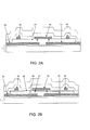
- FIG 12 an alternative implementation is shown where an additional signal line 103 is directly electrically connected to electrode region 100, creating a single pole, six throw design.
- This implementation has the advantage that the electrical signal only has to go through a single contact area 21 instead of through two contact areas 21 when going from electrode 103 to any of the output electrodes lines 10 (as opposed to travelling between two signal lines 10). The resistance and losses are therefore lower.
- This implementation can also be used in Figs. 3 , 4 , 6 , 9 , 10 , 11 by connecting the additional signal line 103 to the movable contact region16.
- n-pole m-throw switch can be created by segmenting the movable electrode into different electrically separated regions, with one region for each pole of the switch, and a number of signal lines associated with each region giving rise to the desired number of throws.
- a general n-pole m-throw switch can also be created by combining several of the proposed switch devices.
- the manufacturing steps to fabricate the switch designs above are routine to those skilled in the art, and differ from the known techniques only in the patterning selected.
- One difference in terms of processing between the device described and the devices of Figure 3 is that it can be beneficial to include one more isolating dielectric layer.
- This layer enables the crossing of the two metal layers without making contact between them, and can also prevent direct contact between the actuation electrodes 18 and the signal electrodes 10. This is helpful to electrically connect individual electrodes on chip.
- This extra layer is not essential, however it can simplify switch design and interconnect layout and it can increase reliability because direct contact between electrodes 18 and 12 in Figure 2 is prevented.
- the switch arrangement could be placed upside down on top of the substrate, such that the movable parts become fixed and some of the fixed parts become movable.
- galvanic switches analogue switches, RF switches, high power switches, high-bandwidth digital switches.
Landscapes
- Micromachines (AREA)
Abstract
Description
- This invention relates to MEMS switches, particularly MEMS galvanic switches.
- A MEMS galvanic switch comprises a first electrode arrangement that is present on a substrate and a movable element that overlies at least partially the first electrode arrangement. The movable element is movable towards the substrate between a first and a second position by application of an actuation voltage, providing electrostatic attraction.
- In the first position, the movable element is separated from the substrate by a gap. The movable element comprises a second electrode that faces the first electrode arrangement. In the second position (closed switch) first and second electrodes are in mechanical and electrical contact with each other.
- Known MEMS switches of this type can use electrostatic actuation in which electrostatic forces resulting from actuation drive voltages cause the switch to close. An alternative type uses piezoelectric actuation, in which drive signals cause deformation of a piezoelectric beam. This invention relates particularly to electrostatic switches.
- Electrostatic galvanic MEMS switches are promising devices. They usually have 4 terminals: signal input, signal output, and two actuation terminals, one of which usually is kept at ground potential. By varying the voltage on the other actuation terminal, an electrostatic force is generated which pulls the movable structure downward. If this voltage is high enough, one or more contact dimple electrodes will touch and will provide a galvanic connection between the two signal terminals.
-
Figures 1 and2 show one possible design of MEMS galvanic switch designed in accordance with known design principles. - In
Figure 1 , the cross hatched pattern is the bottom electrode layer. This defines the signal inelectrode 10, the signal outelectrode 12 and loweractuation electrode pads 18a. As shown, theactuation electrode pads 18a are grounded. - A top electrode layer defines the
movable contact element 16 as well as thesecond actuation electrode 18b to which a control signal ("DC act") is applied. - The
second actuation electrode 18b has a large area overlapping theground actuation pads 18a so that a large electrostatic force can be generated. However, because thetop actuation electrode 18b and themovable contact element 16 are formed from the same layer, a space is provided around themovable contact element 16. Furthermore, overlap of the actuation electrodes and the signal lines is undesirable, as explained further below. -
Figures 2A and 2B show two versions of the device in cross section taken through a vertical line inFigure 1 . The same components are given the same reference numbers.Figures 2A and 2B additionally show thesubstrate arrangement 2 and thegap 20 beneath themovable contact element 16. Theactuation electrode 18 can be covered on one side with an electrically insulating layer as shown inFigure 2A , or it can be covered on both sides with electrically insulating layers as shown inFigure 2B , which shows an additionalinsulating layer 22. - The connection between the signal input and signal output electrodes is made by the movable contact electrode which has two
contact dimples 21 as shown inFigure 2 . Galvanic MEMS switches can achieve low resistances Ron of less then 0.5 Ohm when they are switched on, and high isolation with small parasitic capacitance when they are off (Coff< 50 fF). Typical dimensions are 50 to 200µm outer diameter of theactuation electrode 18. - The device is manufactured in well known manner, in which sacrificial etching defines the
gap 20. - Electrostatically actuated galvanic MEMS switches typically consist of a circular, suspended membrane that has a central portion that connects the two RF signal electrodes when it is deflected downwards. The device provides a single signal path and the actuation electrode is segmented in two equal parts positioned on opposing sides of the RF signal electrodes. This is shown in
Figure 1 . - An alternative arrangement of the galvanic MEMS switch has been considered by the applicant, having an oval shape to replace the circular shape of
Figure 1 . The main purpose of the oval shape is to mechanically strengthen the suspended membrane on the axis parallel to the RF electrode. During actuation, the membrane bends less across this axis than for a circular device. This gives the device a lower actuation voltage, a larger working range (voltage range between contact closure between 16 and 12 and pull-in of the switch's actuation electrode 18) and a larger maximum achievable contact force. - A disadvantage of this approach is that the RF electrodes need to be relatively long, which causes additional unwanted series resistance.
- Another drawback of known designs is that many MEMS switches are required in order to implement more complicated switching functionality.
- The invention is directed to these drawbacks of existing MEMS switch designs.
- According to a first aspect of the invention, there is provided a MEMS switch, comprising:
- a substrate;
- at least first, second and third signal lines over the substrate, which each terminate at a connection region;
- a lower actuation electrode arrangement over the substrate;
- a movable contact electrode suspended over the connection regions for making or breaking electrical contact between at least two of the three connection regions; and
- an upper actuation electrode arrangement provided over the lower actuation electrode arrangement.
- This design has more than two signal lines (and corresponding connection regions), but a single movable electrode for forming connections between the signal lines.
- The signal lines can comprise radial connection lines, and the lower actuation electrode arrangement can comprise arcuate portions between the radial connection lines, which together have a circular outer shape, interrupted by the radial signal lines.
- In this way, at least the lower actuation electrode arrangement is segmented into more than two parts. The actuation electrode parts can be spread evenly around the area of the suspended membrane, so that the deformation of the membrane during actuation is made more symmetric, but without requiring elongated signal lines or electrodes.
- The presence of more than two RF signal electrodes also enables the device to perform additional functions. In particular, the actuation electrode segments can be actuated separately, thus giving the user the choice which electrodes are connected during actuation. The design can be designed for use as an n-pole m-throw switch.
- In one example, the switch comprises four signal lines, which are connected at their connection regions as two pairs, wherein the switch is for making or breaking electrical contact between the two pairs of signal lines.
- This defines a single pole single throw switch, but which has four signal lines to provide a symmetric actuation force.
- In another example, the switch comprises four signal lines, wherein the movable electrode is tiltable in dependence on which actuation electrode portions are operated, and the switch is for making or breaking electrical contact between any selected pair of adjacent signal lines.
- This provides a more versatile switch, in that there are four possible switch functions that can be implemented.
- In another example, the switch comprises four signal lines, wherein the movable contact electrode comprises a first contact portion associated with one pair of adjacent signal lines and a second contact portion associated with the other pair of signal lines, wherein the movable electrode is tiltable in dependence on which actuation electrode portions are operated, and the switch is for selectively making or breaking electrical contact between one of the pairs of signal and/or the other of the pairs of signal lines.
- This design can be used as a double pole single throw switch, even though there is only one controlled movable electrode.
- In another example, the switch comprises three signal lines, wherein the movable electrode is tiltable in dependence on which actuation electrode portions are operated, and the switch is for selectively making or breaking electrical contact between one signal lines and one or other of the other two signal lines.
- This design enables a single pole double throw switch to be formed.
- In another set of examples, the lower actuation electrode arrangement comprises one independently drivable actuation electrode associated with each signal line, and wherein the movable electrode comprises a plate, wherein regions of the plate are individually drivable into contact with an associated connection region, such that any one signal line can be connected by the movable contact electrode to any other signal line.
- This arrangement is even more versatile, in that large numbers of electrode lines (for example 6 or more) can be interconnected in a very adaptable way.
- For example, the signal lines can be arranged so that the connection regions form as a closed shape, with the signal lines extending outwardly from the closed shape, and wherein a central part of the movable electrode plate comprises a fixed anchor region, such that the movable parts of the electrode plate comprise edge regions. The shape can comprises a rectangle or a regular polygon.
- This design can be used generally for an n pole m throw switch, in that the signal lines can be configured in any arrangement, and the movable electrode can be segmented as desired.
- These and other aspects of the device of the invention will be further explained with reference to the Figures, in which:
-
Figure 1 shows a plan view of a known galvanic piezoelectric MEMS switch; -
Figure 2 shows the switch ofFigure 1 in cross section; -
Figure 3 shows the configuration of the switch in schematic form, as well as a proposed modification to the layout, -
Figure 4 shows an example of switch of the invention in schematic form; -
Figure 5 is used to show the advantages of the design ofFigure 4 ; -
Figure 6 shows two further examples of switch of the invention in schematic form; -
Figures 7 and8 are used to show the operation characteristics of one of the designs ofFigure 6 ; -
Figure 9 shows a further example of switch of the invention in schematic form; -
Figure 10 shows a further example of switch of the invention in schematic form; -
Figure 11 shows a further example of switch of the invention in schematic form; and -
Figure 12 shows a further example of switch of the invention in schematic form. - The invention provides a MEMS switch in which at least first, second and third signal lines are provided over the substrate, which each terminate at a connection region. In one embodiment, the signal lines comprise radial connection lines evenly angularly spaced, and a lower actuation electrode comprises arcuate portions between the radial connection lines, which together have a circular outer shape, interrupted by the radial signal lines. This provides a symmetrical actuation force and also enables various possible switch functions. In another embodiment. a movable contact electrode is suspended over the connection regions for making or breaking electrical contact between at least two of the connection regions, and the movable electrode comprises a plate, wherein regions of the plate are individually drivable into contact with an associated connection region, such that any one signal line can be connected by the movable contact electrode to any other signal line. This provides a versatile design.
- The figures below show various MEMS switch layouts of the invention. All figures have been simplified so that only the relevant details are shown, in particular the signal line shapes, actuation electrode shapes and contact designs. The further implementation details are standard, for example as described further with reference to
Figures 1 and2 . - In
Figure 3 and the following figures, the segmented arcuate hatchedareas 18 represent the actuation electrodes. For simplicity, asingle reference 18 is used to represent bothactuation electrodes Figure 1 ) and in the top layer that forms the suspended membrane. Thus, theregions 18 are intended to represent the shape of both the lower and upper actuation electrodes. The drawings are only schematic and the upper and lower electrodes do not have to be of the identical shape, although it is the overlap between them that provides the actuation force. The radial lines 10 represent the RF signal electrodes (and they may be the RF input or RF output lines); they are only present in the lower layer. Thedots 21 in the central area represent the dimples that make contact to the RF electrodes, as most clearly seen in the cross section ofFigure 2 . The dimples are electrically connected to each other by the central circular oroval regions 16 corresponding to thecontact element 16 ofFigure 1 . Both the dimples and circular/oval regions are present only on the suspended membrane. - By applying an electric potential difference between the actuation electrodes on the lower layer with respect to the actuation electrodes on the upper layer, the device is actuated. The suspended membrane deflects downwards and the dimples make contact to the RF signal electrodes. This closes the switch.
-
Figure 3 shows the known MEMS switches. The right-hand device is a basic circular switch and the left hand device represents the modification having an oval shape mentioned above. -
Figure 4 shows a first example of switch of the invention. - This version has two
dimples 21, and is a single pole single throw switch. Although there are four signal lines, they are coupled in pairs, so that there is only one signal path across the switch (i.e. single pole). The design is single-throw, in that contact is either made or broken. - The signal lines comprise radial connection lines evenly angularly spaced. This means there are four actuation electrode portions, shaped as sectors of a circle and sandwiched between adjacent radial connection lines 10. The overall outer shape is circular.
- When the device is actuated, one pair of signal lines is electrically connected to the other pair.
-
Figure 5 shows the results of a Finite Element simulation, which indicates that the deflection of the membrane (as represented by the concentric rings, which represent equal height areas) is nicely circular symmetric. InFigure 5 , theactuation electrodes 18 are shown but the RF electrodes are not shown. Thedimples 21 are indicated with circles in the centre. At touchdown (i.e. when contact is initially made), the rings are circular as shown in the left image, while at pull-in (after further actuation beyond initial touchdown) they deform as shown in the right image. - This indicates bending of the membrane because of the presence of the dimples.
- By way of example, the performance of a design in accordance with the invention has been compared with a corresponding conventional design, with only the electrode layout altered (i.e. comparing a design of
Figure 4 with the right image ofFigure 3 , with the same layer thicknesses and materials and the same outer diameter of the circular actuation electrode). - In the results below, Vt is the voltage required for first contact, Vpi is the final pull in voltage, Range is the difference between Vpi and Vt (with Vt the voltage at which the contact is first made and Vpi the voltage at which the actuation electrodes collapse due to pull-in) and Fc,max is the maximum contact force.
- The
Figure 3 design gave the following values: - Vt=59.2 V
- Vpi=64.6 V
- Range = 5.4 V
- Fc,max =68 µN
- The
Figure 4 design gave the following values - Vt= 50.6 V
- Vpi= 58.5 V
- Range = 7.9 V
- Fc,max = 93 µN
- This simulation shows the advantages of the new design because the contact force has increased, the pull-in voltage has decreased and the range (Vpi-Vt) has increased. A small drawback is that the restoring force decreases by 15%. This is not detrimental for correct operation of the device because the restoring force has a much larger margin.
- The arrangement of
Figure 4 functions in a similar way to a conventional switch, in that there are two possible settings - contact regions connected or not connected. - In preferred examples of the invention, the use of three or more signal lines with a shared movable electrode gives the switch greater versatility. In particular, the can have switch has three or more settings, for example (i) a first configuration of signal line connections, (ii) a different second configuration of signal line connections and (iii) no signal line connections.
- The first two configurations can for example comprise the connection between a selected pair out of the three (or more) signal lines. This means that the first two configurations leave at least one signal line unconnected. To enable these multiple configurations, the single movable electrode needs to be able to close in different ways. In the examples below, the movable electrode is able to tilt as part of the closing function, so that different closure configurations can be defined.
-
Figure 6 shows two further embodiments. The left image shows a switch that is designed to make contact between any pair of adjacent RF signal electrodes. For this purpose, the voltage on eachactuation electrode 18 can be adjusted individually. The movable electrode will then tilt in the desired direction, towards the centre of the operated actuation electrode segment. - In this design, each signal line terminates at its own electrode. The electrodes are arranged in a ring. The movable electrode comprises a contact which has a contact area that covers the ring of electrodes. Depending how it is tilted, it can connect any adjacent pair of electrodes.
- The right image shows a switch that can switch two balanced RF signals simultaneously or independently, depending on how the actuation electrodes are connected.
- In this design, each signal line again terminates at its own electrode. The electrodes are arranged in a ring. The movable electrode comprises a contact which has two
separate contact areas -
Figure 7 shows simulation results for the design ofFigure 6 . It shows one electrode (A) driven with one voltage VA and the other three (B) driven with another voltage VB. - With a well-chosen sequence of voltages on the four quadrants of the switch it is possible to land any set of adjacent dimples.
- In the graph of
Figure 7 ,plot 70 is the voltage VA applied to the single electrode A andplot 72 is the voltage VB applied to the set of three electrodes B. The contact dimples are numbered C1 through C4 with corresponding forces FC1 through FC4. - The graph on the right shows that in the simulation the voltage on all electrodes is ramped up to 50 volts, enough for touch down of all four dimples. Thereafter, the voltage on actuation electrode A is further increased, while the voltage on electrodes B is reduced.
-
Figure 8 shows a graph of the resulting contact force on all four dimples. - It is possible to have a high contact force on dimples C1 and C2, and an (almost) zero contact force on dimples C3 and C4.
- The performance can be optimised based on size and shape of the individual components of the device and the sequence of signals applied to the actuation electrodes.
- Many more variations are possible.
- For example,
Figure 9 shows a single pole double throw switch. - In this design, there are three
signal lines 10. Each signal line terminates at its own electrode. The electrodes are arranged in a ring. The movable electrode comprises a contact which has a contact area that covers the ring of electrodes. Depending how it is tilted, it can connect any adjacent pair of electrodes. Thus, one input electrode can be connected to either of the other two signal lines as output, giving single pole double throw functionality. - The examples above provide a signal line and actuation electrode design for a single switch. The invention also provides designs which provide multiple switch elements in a combined compact design, in particular sharing the movable electrode. Thus, the same concept of a shared movable electrode for three or more signal lines is applied, but the signal lines are not distributed among a set of lower actuation electrodes; instead each signal line has its own lower actuation electrode, for example a circular actuation electrode which is interrupted only by the single associated signal line. Each such signal line and actuation electrode can be though of as a switch element, and the movable electrode is shared between the switch elements.
- Thus, each switch element has an independently
drivable actuation electrode 18 and a single associatedsignal line 10. - The shared movable contact electrode (again suspended over the connection regions of the signal lines) comprises a plate. Regions of the plate are individually drivable into contact with an associated connection region, such that any one signal line can be connected by the movable contact electrode to any other signal line.
-
Figure 10 shows a first example, and which can be used to implement a multiple pole - multiple throw switch. - In this figure, in
area 100 both top metal and bottom metal are present, so that there is no suspended membrane. This defines an electrode region. The two metal layers are permanently connected to each other in this area. This defines a central anchor region, and the peripheral regions are the movable parts - The device has six
RF electrode lines 10, each with its own suspended membrane andcorresponding actuation electrode 18. The sixdimples 21 are all connected to each other through the top metal and through the low-ohmic lower metal by virtue of the central area. - When a voltage is applied to any set of two actuation electrodes, a connection is made between the corresponding RF signal electrodes. Essentially, the
movable electrode 102 can be deformed so that different portions can be brought into contact with the associated signal line. - This variation is not limited to 6 electrodes, and not to its rectangular shape either. A hexagonal alternative is shown in
Figure 11 . - In
Figure 12 an alternative implementation is shown where anadditional signal line 103 is directly electrically connected toelectrode region 100, creating a single pole, six throw design. This implementation has the advantage that the electrical signal only has to go through asingle contact area 21 instead of through twocontact areas 21 when going fromelectrode 103 to any of the output electrodes lines 10 (as opposed to travelling between two signal lines 10). The resistance and losses are therefore lower. This implementation can also be used inFigs. 3 ,4 ,6 ,9 ,10 ,11 by connecting theadditional signal line 103 to the movable contact region16. - These designs enable multiple pole designs (in that different signal lines can be part of different circuits) and/or multiple throw designs (in that one signal line can be connected to a choice of other signal lines).
- If all contact dimples are connected, the different circuits for a multiple throw switch cannot be operated independently. However a general n-pole m-throw switch can be created by segmenting the movable electrode into different electrically separated regions, with one region for each pole of the switch, and a number of signal lines associated with each region giving rise to the desired number of throws. A general n-pole m-throw switch can also be created by combining several of the proposed switch devices.
- The manufacturing steps to fabricate the switch designs above are routine to those skilled in the art, and differ from the known techniques only in the patterning selected. One difference in terms of processing between the device described and the devices of
Figure 3 is that it can be beneficial to include one more isolating dielectric layer. This layer enables the crossing of the two metal layers without making contact between them, and can also prevent direct contact between theactuation electrodes 18 and thesignal electrodes 10. This is helpful to electrically connect individual electrodes on chip. This extra layer is not essential, however it can simplify switch design and interconnect layout and it can increase reliability because direct contact betweenelectrodes Figure 2 is prevented. This is thelayer 22 inFigure 2 . The switch arrangement could be placed upside down on top of the substrate, such that the movable parts become fixed and some of the fixed parts become movable. - The application is of particular interest for galvanic switches (analogue switches, RF switches, high power switches, high-bandwidth digital switches).
- Various other modifications will be apparent to those skilled in the art.
Claims (13)
- A MEMS switch, comprising:a substrate (2);at least first, second and third signal lines (10) over the substrate, which each terminate at a connection region (21);a lower actuation electrode arrangement (18) over the substrate;a movable contact electrode (16) suspended over the connection regions (21) for making or breaking electrical contact between at least two of the three connection regions (21); andan upper actuation electrode arrangement (18) provided over the lower actuation electrode.
- A switch as claimed in claim 1, wherein the signal lines (10) comprise radial connection lines, and wherein the lower actuation electrode arrangement (18) comprises arcuate portions between the radial connection lines, which together have a circular outer shape, interrupted by the radial signal lines.
- A switch as claimed in claim 2, wherein the radial connection lines are evenly angularly spaced.
- A switch as claimed in claim 2 or 3, comprising four signal lines (10), which are connected at their connection regions as two pairs, wherein the switch is for making or breaking electrical contact between the two pairs of signal lines.
- A switch as claimed in claim 2 or 3, comprising four signal lines (10), wherein the movable contact electrode (16) is tiltable in dependence on which actuation electrode portions are operated, and the switch is for making or breaking electrical contact between any selected pair of adjacent signal lines.
- A switch as claimed in claim 2 or 3, comprising four signal lines (10), wherein the movable contact electrode comprises a first contact portion (16a) associated with one pair of adjacent signal lines and a second contact portion (16b) associated with the other pair of signal lines, wherein the movable contact electrode (16a,16b) is tiltable in dependence on which actuation electrode portions are operated, and the switch is for selectively making or breaking electrical contact between one of the pairs of signal and/or the other of the pairs of signal lines.
- A switch as claimed in claim 2 or 3, comprising three signal lines (10), wherein the movable electrode (16) is tiltable in dependence on which actuation electrode portions are operated, and the switch is for selectively making or breaking electrical contact between one signal line and one or other of the other two signal lines.
- A MEMS switch as claimed in claim 1, wherein:the lower actuation electrode arrangement (18) comprises one independently drivable actuation electrode (18) associated with each signal line (10), and wherein the movable contact electrode (102) comprises a plate, wherein regions of the plate (102) are individually drivable into contact with an associated connection region (21), such that any one signal line (10) can be connected by the movable contact electrode (102) to any other signal line (10).
- A switch as claimed in claim 8, wherein the signal lines (10) are arranged so that the connection regions (21) form as a closed shape, with the signal lines (10) extending outwardly from the closed shape, and wherein a central part (100) of the movable electrode plate (102) comprises a fixed anchor region, such that the movable parts of the electrode plate (102) comprise edge regions.
- A switch as claimed in claim 9, wherein the shape comprises a rectangle or a regular polygon.
- A switch as claimed in claim 8, 9 or 10, comprising at least 6 signal lines (10).
- A switch as claimed in any preceding claim, wherein the upper actuation electrode (18) and the movable contact electrode (16) are formed from the same layer.
- A switch as claimed in any preceding claim, wherein the lower actuation electrode (18) and the signal lines (10) are formed from the same layer.
Priority Applications (3)
| Application Number | Priority Date | Filing Date | Title |
|---|---|---|---|
| EP10193180.6A EP2458610B1 (en) | 2010-11-30 | 2010-11-30 | MEMS switch |
| CN201110386333.9A CN102543592B (en) | 2010-11-30 | 2011-11-29 | Mems switch |
| US13/306,675 US8716619B2 (en) | 2010-11-30 | 2011-11-29 | MEMS switch |
Applications Claiming Priority (1)
| Application Number | Priority Date | Filing Date | Title |
|---|---|---|---|
| EP10193180.6A EP2458610B1 (en) | 2010-11-30 | 2010-11-30 | MEMS switch |
Publications (3)
| Publication Number | Publication Date |
|---|---|
| EP2458610A1 true EP2458610A1 (en) | 2012-05-30 |
| EP2458610A8 EP2458610A8 (en) | 2013-02-06 |
| EP2458610B1 EP2458610B1 (en) | 2013-06-05 |
Family
ID=43844630
Family Applications (1)
| Application Number | Title | Priority Date | Filing Date |
|---|---|---|---|
| EP10193180.6A Not-in-force EP2458610B1 (en) | 2010-11-30 | 2010-11-30 | MEMS switch |
Country Status (3)
| Country | Link |
|---|---|
| US (1) | US8716619B2 (en) |
| EP (1) | EP2458610B1 (en) |
| CN (1) | CN102543592B (en) |
Families Citing this family (2)
| Publication number | Priority date | Publication date | Assignee | Title |
|---|---|---|---|---|
| US9745188B1 (en) * | 2016-02-26 | 2017-08-29 | Infineon Technologies Ag | Microelectromechanical device and method for forming a microelectromechanical device |
| CN108508392A (en) * | 2018-06-21 | 2018-09-07 | 中北大学 | A kind of four beam type Electronic Calibration part of T-type switch |
Citations (4)
| Publication number | Priority date | Publication date | Assignee | Title |
|---|---|---|---|---|
| EP1306869A1 (en) * | 2001-10-24 | 2003-05-02 | Nec Corporation | Electrostatic actuator |
| US20060050360A1 (en) * | 2004-08-19 | 2006-03-09 | Nelson Richard D | Plate-based microelectromechanical switch having a three-fold relative arrangement of contact structures and support arms |
| EP1672661A2 (en) * | 2004-12-17 | 2006-06-21 | Samsung Electronics Co., Ltd. | MEMS switch and method of fabricating the same |
| US20060181377A1 (en) * | 2005-02-17 | 2006-08-17 | Samsung Electronics Co., Ltd. | Switch pad and micro-switch having the same |
Family Cites Families (2)
| Publication number | Priority date | Publication date | Assignee | Title |
|---|---|---|---|---|
| JP4137872B2 (en) * | 2004-03-31 | 2008-08-20 | シャープ株式会社 | Electrostatic actuator, micro switch, micro optical switch, micro optical switch system, communication device, and manufacturing method of electrostatic actuator |
| US8513745B2 (en) | 2008-06-06 | 2013-08-20 | Nxp B.V. | MEMS switch and fabrication method |
-
2010
- 2010-11-30 EP EP10193180.6A patent/EP2458610B1/en not_active Not-in-force
-
2011
- 2011-11-29 CN CN201110386333.9A patent/CN102543592B/en not_active Expired - Fee Related
- 2011-11-29 US US13/306,675 patent/US8716619B2/en active Active
Patent Citations (4)
| Publication number | Priority date | Publication date | Assignee | Title |
|---|---|---|---|---|
| EP1306869A1 (en) * | 2001-10-24 | 2003-05-02 | Nec Corporation | Electrostatic actuator |
| US20060050360A1 (en) * | 2004-08-19 | 2006-03-09 | Nelson Richard D | Plate-based microelectromechanical switch having a three-fold relative arrangement of contact structures and support arms |
| EP1672661A2 (en) * | 2004-12-17 | 2006-06-21 | Samsung Electronics Co., Ltd. | MEMS switch and method of fabricating the same |
| US20060181377A1 (en) * | 2005-02-17 | 2006-08-17 | Samsung Electronics Co., Ltd. | Switch pad and micro-switch having the same |
Also Published As
| Publication number | Publication date |
|---|---|
| EP2458610B1 (en) | 2013-06-05 |
| US8716619B2 (en) | 2014-05-06 |
| US20120305374A1 (en) | 2012-12-06 |
| CN102543592B (en) | 2014-11-26 |
| EP2458610A8 (en) | 2013-02-06 |
| CN102543592A (en) | 2012-07-04 |
Similar Documents
| Publication | Publication Date | Title |
|---|---|---|
| US7212091B2 (en) | Micro-electro-mechanical RF switch | |
| US6307169B1 (en) | Micro-electromechanical switch | |
| JP4262199B2 (en) | Micro electromechanical switch | |
| CN108281286B (en) | Micro-electro-mechanical system (MEMS) variable capacitor devices and related methods | |
| US20020186108A1 (en) | Micro electromechanical switches | |
| EP2969912A1 (en) | Actuator plate partitioning and control devices and methods | |
| USRE45704E1 (en) | MEMS millimeter wave switches | |
| EP2458610B1 (en) | MEMS switch | |
| CN108604517B (en) | Active open MEMS switching device | |
| CN102054628B (en) | Mems switch | |
| WO2007022500A2 (en) | Microelectromechanical switches having mechanically active components which are electrically isolated from components of the switch used for the transmission of signals | |
| TWI576883B (en) | Rf micro-electro-mechanical system (mems) capacitive switch | |
| CN106062914B (en) | MEMS and the method for manufacturing MEMS | |
| US7745747B2 (en) | Microswitch with a first actuated portion and a second contact portion | |
| EP1573769B1 (en) | Microelectromechanical rf switch | |
| TWI533346B (en) | Microelectromechanical switches for steering of rf signals and method for switching an electrical signal | |
| US7218191B2 (en) | Micro-electro mechanical switch designs | |
| US20230140449A1 (en) | Two-stage actuation in mems ohmic relays | |
| JP5483574B2 (en) | MEMS switch | |
| JP7486278B2 (en) | High performance switches for microwave MEMS | |
| CN115083845A (en) | Micro-electro-mechanical system and micro-electro-mechanical system switch | |
| KR20090086879A (en) | Micro matrix relay switch | |
| Ishikawa et al. | Early-stage analysis for MEMS structural optimization II: its application to microrelay reliability | |
| KR20040103039A (en) | RF MEMS switch using residual stress and piezo-driving force |
Legal Events
| Date | Code | Title | Description |
|---|---|---|---|
| PUAI | Public reference made under article 153(3) epc to a published international application that has entered the european phase |
Free format text: ORIGINAL CODE: 0009012 |
|
| AK | Designated contracting states |
Kind code of ref document: A1 Designated state(s): AL AT BE BG CH CY CZ DE DK EE ES FI FR GB GR HR HU IE IS IT LI LT LU LV MC MK MT NL NO PL PT RO RS SE SI SK SM TR |
|
| AX | Request for extension of the european patent |
Extension state: BA ME |
|
| GRAP | Despatch of communication of intention to grant a patent |
Free format text: ORIGINAL CODE: EPIDOSNIGR1 |
|
| 17P | Request for examination filed |
Effective date: 20121130 |
|
| RIC1 | Information provided on ipc code assigned before grant |
Ipc: H01H 59/00 20060101AFI20121217BHEP |
|
| GRAS | Grant fee paid |
Free format text: ORIGINAL CODE: EPIDOSNIGR3 |
|
| GRAA | (expected) grant |
Free format text: ORIGINAL CODE: 0009210 |
|
| AK | Designated contracting states |
Kind code of ref document: B1 Designated state(s): AL AT BE BG CH CY CZ DE DK EE ES FI FR GB GR HR HU IE IS IT LI LT LU LV MC MK MT NL NO PL PT RO RS SE SI SK SM TR |
|
| REG | Reference to a national code |
Ref country code: GB Ref legal event code: FG4D |
|
| REG | Reference to a national code |
Ref country code: CH Ref legal event code: EP |
|
| REG | Reference to a national code |
Ref country code: AT Ref legal event code: REF Ref document number: 616093 Country of ref document: AT Kind code of ref document: T Effective date: 20130615 |
|
| REG | Reference to a national code |
Ref country code: IE Ref legal event code: FG4D |
|
| REG | Reference to a national code |
Ref country code: DE Ref legal event code: R096 Ref document number: 602010007537 Country of ref document: DE Effective date: 20130801 |
|
| REG | Reference to a national code |
Ref country code: AT Ref legal event code: MK05 Ref document number: 616093 Country of ref document: AT Kind code of ref document: T Effective date: 20130605 |
|
| PG25 | Lapsed in a contracting state [announced via postgrant information from national office to epo] |
Ref country code: NO Free format text: LAPSE BECAUSE OF FAILURE TO SUBMIT A TRANSLATION OF THE DESCRIPTION OR TO PAY THE FEE WITHIN THE PRESCRIBED TIME-LIMIT Effective date: 20130905 Ref country code: AT Free format text: LAPSE BECAUSE OF FAILURE TO SUBMIT A TRANSLATION OF THE DESCRIPTION OR TO PAY THE FEE WITHIN THE PRESCRIBED TIME-LIMIT Effective date: 20130605 Ref country code: FI Free format text: LAPSE BECAUSE OF FAILURE TO SUBMIT A TRANSLATION OF THE DESCRIPTION OR TO PAY THE FEE WITHIN THE PRESCRIBED TIME-LIMIT Effective date: 20130605 Ref country code: GR Free format text: LAPSE BECAUSE OF FAILURE TO SUBMIT A TRANSLATION OF THE DESCRIPTION OR TO PAY THE FEE WITHIN THE PRESCRIBED TIME-LIMIT Effective date: 20130906 Ref country code: SI Free format text: LAPSE BECAUSE OF FAILURE TO SUBMIT A TRANSLATION OF THE DESCRIPTION OR TO PAY THE FEE WITHIN THE PRESCRIBED TIME-LIMIT Effective date: 20130605 Ref country code: LT Free format text: LAPSE BECAUSE OF FAILURE TO SUBMIT A TRANSLATION OF THE DESCRIPTION OR TO PAY THE FEE WITHIN THE PRESCRIBED TIME-LIMIT Effective date: 20130605 Ref country code: ES Free format text: LAPSE BECAUSE OF FAILURE TO SUBMIT A TRANSLATION OF THE DESCRIPTION OR TO PAY THE FEE WITHIN THE PRESCRIBED TIME-LIMIT Effective date: 20130916 Ref country code: SE Free format text: LAPSE BECAUSE OF FAILURE TO SUBMIT A TRANSLATION OF THE DESCRIPTION OR TO PAY THE FEE WITHIN THE PRESCRIBED TIME-LIMIT Effective date: 20130605 |
|
| REG | Reference to a national code |
Ref country code: NL Ref legal event code: VDEP Effective date: 20130605 |
|
| REG | Reference to a national code |
Ref country code: LT Ref legal event code: MG4D |
|
| PG25 | Lapsed in a contracting state [announced via postgrant information from national office to epo] |
Ref country code: BG Free format text: LAPSE BECAUSE OF FAILURE TO SUBMIT A TRANSLATION OF THE DESCRIPTION OR TO PAY THE FEE WITHIN THE PRESCRIBED TIME-LIMIT Effective date: 20130905 Ref country code: RS Free format text: LAPSE BECAUSE OF FAILURE TO SUBMIT A TRANSLATION OF THE DESCRIPTION OR TO PAY THE FEE WITHIN THE PRESCRIBED TIME-LIMIT Effective date: 20130605 Ref country code: HR Free format text: LAPSE BECAUSE OF FAILURE TO SUBMIT A TRANSLATION OF THE DESCRIPTION OR TO PAY THE FEE WITHIN THE PRESCRIBED TIME-LIMIT Effective date: 20130605 |
|
| PG25 | Lapsed in a contracting state [announced via postgrant information from national office to epo] |
Ref country code: LV Free format text: LAPSE BECAUSE OF FAILURE TO SUBMIT A TRANSLATION OF THE DESCRIPTION OR TO PAY THE FEE WITHIN THE PRESCRIBED TIME-LIMIT Effective date: 20130605 |
|
| PG25 | Lapsed in a contracting state [announced via postgrant information from national office to epo] |
Ref country code: BE Free format text: LAPSE BECAUSE OF FAILURE TO SUBMIT A TRANSLATION OF THE DESCRIPTION OR TO PAY THE FEE WITHIN THE PRESCRIBED TIME-LIMIT Effective date: 20130605 Ref country code: CZ Free format text: LAPSE BECAUSE OF FAILURE TO SUBMIT A TRANSLATION OF THE DESCRIPTION OR TO PAY THE FEE WITHIN THE PRESCRIBED TIME-LIMIT Effective date: 20130605 Ref country code: EE Free format text: LAPSE BECAUSE OF FAILURE TO SUBMIT A TRANSLATION OF THE DESCRIPTION OR TO PAY THE FEE WITHIN THE PRESCRIBED TIME-LIMIT Effective date: 20130605 Ref country code: PT Free format text: LAPSE BECAUSE OF FAILURE TO SUBMIT A TRANSLATION OF THE DESCRIPTION OR TO PAY THE FEE WITHIN THE PRESCRIBED TIME-LIMIT Effective date: 20131007 Ref country code: IS Free format text: LAPSE BECAUSE OF FAILURE TO SUBMIT A TRANSLATION OF THE DESCRIPTION OR TO PAY THE FEE WITHIN THE PRESCRIBED TIME-LIMIT Effective date: 20131005 Ref country code: SK Free format text: LAPSE BECAUSE OF FAILURE TO SUBMIT A TRANSLATION OF THE DESCRIPTION OR TO PAY THE FEE WITHIN THE PRESCRIBED TIME-LIMIT Effective date: 20130605 |
|
| PG25 | Lapsed in a contracting state [announced via postgrant information from national office to epo] |
Ref country code: RO Free format text: LAPSE BECAUSE OF FAILURE TO SUBMIT A TRANSLATION OF THE DESCRIPTION OR TO PAY THE FEE WITHIN THE PRESCRIBED TIME-LIMIT Effective date: 20130605 Ref country code: NL Free format text: LAPSE BECAUSE OF FAILURE TO SUBMIT A TRANSLATION OF THE DESCRIPTION OR TO PAY THE FEE WITHIN THE PRESCRIBED TIME-LIMIT Effective date: 20130605 Ref country code: PL Free format text: LAPSE BECAUSE OF FAILURE TO SUBMIT A TRANSLATION OF THE DESCRIPTION OR TO PAY THE FEE WITHIN THE PRESCRIBED TIME-LIMIT Effective date: 20130605 |
|
| PLBE | No opposition filed within time limit |
Free format text: ORIGINAL CODE: 0009261 |
|
| STAA | Information on the status of an ep patent application or granted ep patent |
Free format text: STATUS: NO OPPOSITION FILED WITHIN TIME LIMIT |
|
| PG25 | Lapsed in a contracting state [announced via postgrant information from national office to epo] |
Ref country code: DK Free format text: LAPSE BECAUSE OF FAILURE TO SUBMIT A TRANSLATION OF THE DESCRIPTION OR TO PAY THE FEE WITHIN THE PRESCRIBED TIME-LIMIT Effective date: 20130605 |
|
| 26N | No opposition filed |
Effective date: 20140306 |
|
| PG25 | Lapsed in a contracting state [announced via postgrant information from national office to epo] |
Ref country code: IT Free format text: LAPSE BECAUSE OF FAILURE TO SUBMIT A TRANSLATION OF THE DESCRIPTION OR TO PAY THE FEE WITHIN THE PRESCRIBED TIME-LIMIT Effective date: 20130605 |
|
| REG | Reference to a national code |
Ref country code: DE Ref legal event code: R097 Ref document number: 602010007537 Country of ref document: DE Effective date: 20140306 |
|
| PG25 | Lapsed in a contracting state [announced via postgrant information from national office to epo] |
Ref country code: MC Free format text: LAPSE BECAUSE OF FAILURE TO SUBMIT A TRANSLATION OF THE DESCRIPTION OR TO PAY THE FEE WITHIN THE PRESCRIBED TIME-LIMIT Effective date: 20130605 |
|
| REG | Reference to a national code |
Ref country code: FR Ref legal event code: ST Effective date: 20140731 |
|
| REG | Reference to a national code |
Ref country code: IE Ref legal event code: MM4A |
|
| PG25 | Lapsed in a contracting state [announced via postgrant information from national office to epo] |
Ref country code: IE Free format text: LAPSE BECAUSE OF NON-PAYMENT OF DUE FEES Effective date: 20131130 |
|
| PG25 | Lapsed in a contracting state [announced via postgrant information from national office to epo] |
Ref country code: FR Free format text: LAPSE BECAUSE OF NON-PAYMENT OF DUE FEES Effective date: 20131202 |
|
| PGFP | Annual fee paid to national office [announced via postgrant information from national office to epo] |
Ref country code: GB Payment date: 20141024 Year of fee payment: 5 Ref country code: DE Payment date: 20141023 Year of fee payment: 5 |
|
| PG25 | Lapsed in a contracting state [announced via postgrant information from national office to epo] |
Ref country code: SM Free format text: LAPSE BECAUSE OF FAILURE TO SUBMIT A TRANSLATION OF THE DESCRIPTION OR TO PAY THE FEE WITHIN THE PRESCRIBED TIME-LIMIT Effective date: 20130605 |
|
| PG25 | Lapsed in a contracting state [announced via postgrant information from national office to epo] |
Ref country code: TR Free format text: LAPSE BECAUSE OF FAILURE TO SUBMIT A TRANSLATION OF THE DESCRIPTION OR TO PAY THE FEE WITHIN THE PRESCRIBED TIME-LIMIT Effective date: 20130605 Ref country code: CY Free format text: LAPSE BECAUSE OF FAILURE TO SUBMIT A TRANSLATION OF THE DESCRIPTION OR TO PAY THE FEE WITHIN THE PRESCRIBED TIME-LIMIT Effective date: 20130605 |
|
| REG | Reference to a national code |
Ref country code: CH Ref legal event code: PL |
|
| PG25 | Lapsed in a contracting state [announced via postgrant information from national office to epo] |
Ref country code: CH Free format text: LAPSE BECAUSE OF NON-PAYMENT OF DUE FEES Effective date: 20141130 Ref country code: HU Free format text: LAPSE BECAUSE OF FAILURE TO SUBMIT A TRANSLATION OF THE DESCRIPTION OR TO PAY THE FEE WITHIN THE PRESCRIBED TIME-LIMIT; INVALID AB INITIO Effective date: 20101130 Ref country code: MK Free format text: LAPSE BECAUSE OF FAILURE TO SUBMIT A TRANSLATION OF THE DESCRIPTION OR TO PAY THE FEE WITHIN THE PRESCRIBED TIME-LIMIT Effective date: 20130605 Ref country code: LI Free format text: LAPSE BECAUSE OF NON-PAYMENT OF DUE FEES Effective date: 20141130 Ref country code: LU Free format text: LAPSE BECAUSE OF NON-PAYMENT OF DUE FEES Effective date: 20131130 |
|
| PG25 | Lapsed in a contracting state [announced via postgrant information from national office to epo] |
Ref country code: MT Free format text: LAPSE BECAUSE OF FAILURE TO SUBMIT A TRANSLATION OF THE DESCRIPTION OR TO PAY THE FEE WITHIN THE PRESCRIBED TIME-LIMIT Effective date: 20130605 |
|
| REG | Reference to a national code |
Ref country code: DE Ref legal event code: R119 Ref document number: 602010007537 Country of ref document: DE |
|
| GBPC | Gb: european patent ceased through non-payment of renewal fee |
Effective date: 20151130 |
|
| PG25 | Lapsed in a contracting state [announced via postgrant information from national office to epo] |
Ref country code: GB Free format text: LAPSE BECAUSE OF NON-PAYMENT OF DUE FEES Effective date: 20151130 Ref country code: DE Free format text: LAPSE BECAUSE OF NON-PAYMENT OF DUE FEES Effective date: 20160601 |
|
| PG25 | Lapsed in a contracting state [announced via postgrant information from national office to epo] |
Ref country code: AL Free format text: LAPSE BECAUSE OF FAILURE TO SUBMIT A TRANSLATION OF THE DESCRIPTION OR TO PAY THE FEE WITHIN THE PRESCRIBED TIME-LIMIT Effective date: 20130605 |