EP2458529A1 - Large area monitoring device - Google Patents
Large area monitoring device Download PDFInfo
- Publication number
- EP2458529A1 EP2458529A1 EP11191126A EP11191126A EP2458529A1 EP 2458529 A1 EP2458529 A1 EP 2458529A1 EP 11191126 A EP11191126 A EP 11191126A EP 11191126 A EP11191126 A EP 11191126A EP 2458529 A1 EP2458529 A1 EP 2458529A1
- Authority
- EP
- European Patent Office
- Prior art keywords
- cell
- monitoring device
- core cell
- cells
- antenna
- Prior art date
- Legal status (The legal status is an assumption and is not a legal conclusion. Google has not performed a legal analysis and makes no representation as to the accuracy of the status listed.)
- Withdrawn
Links
Images

Classifications
-
- G—PHYSICS
- G06—COMPUTING OR CALCULATING; COUNTING
- G06K—GRAPHICAL DATA READING; PRESENTATION OF DATA; RECORD CARRIERS; HANDLING RECORD CARRIERS
- G06K19/00—Record carriers for use with machines and with at least a part designed to carry digital markings
- G06K19/06—Record carriers for use with machines and with at least a part designed to carry digital markings characterised by the kind of the digital marking, e.g. shape, nature, code
- G06K19/067—Record carriers with conductive marks, printed circuits or semiconductor circuit elements, e.g. credit or identity cards also with resonating or responding marks without active components
- G06K19/07—Record carriers with conductive marks, printed circuits or semiconductor circuit elements, e.g. credit or identity cards also with resonating or responding marks without active components with integrated circuit chips
- G06K19/077—Constructional details, e.g. mounting of circuits in the carrier
- G06K19/07749—Constructional details, e.g. mounting of circuits in the carrier the record carrier being capable of non-contact communication, e.g. constructional details of the antenna of a non-contact smart card
-
- G—PHYSICS
- G06—COMPUTING OR CALCULATING; COUNTING
- G06K—GRAPHICAL DATA READING; PRESENTATION OF DATA; RECORD CARRIERS; HANDLING RECORD CARRIERS
- G06K19/00—Record carriers for use with machines and with at least a part designed to carry digital markings
- G06K19/06—Record carriers for use with machines and with at least a part designed to carry digital markings characterised by the kind of the digital marking, e.g. shape, nature, code
- G06K19/067—Record carriers with conductive marks, printed circuits or semiconductor circuit elements, e.g. credit or identity cards also with resonating or responding marks without active components
- G06K19/07—Record carriers with conductive marks, printed circuits or semiconductor circuit elements, e.g. credit or identity cards also with resonating or responding marks without active components with integrated circuit chips
- G06K19/0723—Record carriers with conductive marks, printed circuits or semiconductor circuit elements, e.g. credit or identity cards also with resonating or responding marks without active components with integrated circuit chips the record carrier comprising an arrangement for non-contact communication, e.g. wireless communication circuits on transponder cards, non-contact smart cards or RFIDs
-
- Y—GENERAL TAGGING OF NEW TECHNOLOGICAL DEVELOPMENTS; GENERAL TAGGING OF CROSS-SECTIONAL TECHNOLOGIES SPANNING OVER SEVERAL SECTIONS OF THE IPC; TECHNICAL SUBJECTS COVERED BY FORMER USPC CROSS-REFERENCE ART COLLECTIONS [XRACs] AND DIGESTS
- Y10—TECHNICAL SUBJECTS COVERED BY FORMER USPC
- Y10T—TECHNICAL SUBJECTS COVERED BY FORMER US CLASSIFICATION
- Y10T29/00—Metal working
- Y10T29/49—Method of mechanical manufacture
- Y10T29/49002—Electrical device making
- Y10T29/49016—Antenna or wave energy "plumbing" making
- Y10T29/49018—Antenna or wave energy "plumbing" making with other electrical component
Definitions
- the present disclosure relates generally to the monitoring of physical, chemical and/or geometrical parameters over large structures wherein it is necessary to monitor certain parameters in a "distributed" manner over extended areas of the structure.
- Prior patent application No. VA2010A000018 filed on February 26, 2010 of the same applicants/assignee, describes a multi-cell flexible sheet of organic polymer constitution, of finite or theoretically unlimited length, composed of monolithically fabricated array of one or more types of cells of same or different functionalities (e.g. sensor cells, active pixel cells of a large size display), juxtaposed among them to constitute a multicell sheet eventually supported on a flexible film.
- Such a bi-dimensional "tablecloth" array of self-consistent integrated circuit cells could be cut to pieces of size tailored for the need of the specific application without impairing the operability of all the cells spared by the cutting and eventually serve as a magazine of individually severable cells of autonomous operability.
- the multi-cell flexible sheet remains particularly useful for applications requiring a generally large area "pixel-like" array of independently functioning cells, each having an energy storage element for powering the functional circuits of the cell and an optoelectronic device for communicating with the external world.
- Conductive boundary strips among the cells provides electrical paths of common supply rails and/or of input/output nodes of the cells.
- a novel architecture has been found that overcomes the above discussed drawbacks of prior systems by devising self consistent monitoring devices (modules) that are replicable over a continuous flexible substrate preferably of organic polymeric constitution, eventually supported on a flexible ribbon that may be a textile fabric or a fiber-reinforced plastic film, substantially in a bi-dimensionally extending tablecloth-like array of identical or different devices (modules), each covering a relatively extended surface area of a monitored structure or body.
- Each self consistent monitoring device comprises a core cell including a monolithically integrated functional circuitry and RF coupling tag means including a tag antenna, integrated or formed onto the IC chip by post processing, adapted to make wirelessly RF identifiable and excitable the single module among the neighbour modules of the tablecloth array, and to exchange data with a reader device via a far-field or near-field electromagnetic coupling with an antenna of the reader device or via a far-field or near-field multiple electromagnetic or magnetic couplings, for example through concatenated electromagnetic expansions, in a substantially wireless manner with neighbor modules, or alternatively even with a wire connection to access terminals or pads arranged along one or more perimeter sides of the bi-dimensionally extended tablecloth array of self consistent surface monitoring modules.
- the core cell may be energized by rectifying a suitably concentrated RF electromagnetic energy transferred by the reader device upon coupling with the core cell to acquire data sensed by its corolla sensor cells or alternatively, have an embedded energy source in the form of a micro-battery or of a photovoltaic generation device eventually associated to a an embedded storage element, as disclosed in the already cited prior patent application No. VA2010A000018 , of the same applicants/assignee.
- the monolithically integrated functional circuitry of each core cell includes al least a resonance capacitor, a modulator, a rectifier circuit, a charge-pump circuit, a detection circuit and analog and logic signal processing circuits.
- Each self consistent monitoring device or module has at least a one tier corolla of identical or different sensor cells around said core cell, covering a substantially enlarged area of the surface of a monitored structure or body onto which the multi-cellular monitoring device is applied that is a multiple of the individual surface area of a single sensor cell of the corolla.
- Each sensor cell is adapted to convert a change of a geometrical, physical or chemical parameter or state at its location over the surface of the monitored structure or body, and any such change and location of occurrence is detected/recognized by the detection and signal processing circuit of the core cell, upon being RF excited by said reader device.
- the novel approach contemplates "monolithically" replicable units (monitoring devices) endowed with a geometrically ordered plurality of identical or different sensors cells that thus cover a proportionately extended area of the surface of the structure or body to be monitored, providing for the detection of parameter changes and their location of occurrence over the covered area of the singly readable unit.
- This besides making a so composed monolithic unit (severed from tablecloth array magazine ribbon) usable per se to gather information on events and locations of occurrence over an extended area, makes the monitoring of vast surfaces significantly less burdensome by reducing the number of data acquisition nodes.
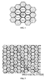
- FIG. 1 is an exemplary highlighted layout of an elementary self consistent monitoring device (module) juxtaposedly replicable in a bi-dimensional tablecloth array in a substantially flexible all-organic multilayer polymer base monolithically in which the functional circuits of the device are monolithically integrated, eventually embedding also silicon-base integrated circuit chips functionally connected to the organic integrated circuit.
- module an elementary self consistent monitoring device juxtaposedly replicable in a bi-dimensional tablecloth array in a substantially flexible all-organic multilayer polymer base monolithically in which the functional circuits of the device are monolithically integrated, eventually embedding also silicon-base integrated circuit chips functionally connected to the organic integrated circuit.
- the shape of the core cell RFID and of the corolla cells SENSOR may be of any geometric shape: polygonal, disc-like, oblong, etc. Cell shapes and arrangements that permit to enhance a close packing together of the sensing areas of the SENSOR cells and of these with the central core cell RFID are preferable.
- the size of the cells and thence of the unitary monitoring device may be as small as allowed by the definition limits of the printing techniques used in the integration process if a fine granularity of surface sensing points is important for the intended surface monitoring application, or as large as desirable for applications wherein an extended coverage of relatively vast surfaces is a dominant requisite.
- Organic base cells may have sizes in the order of several centimeters, therefore a single replicable unitary monitoring device may cover an area of the surface of the monitored structure or body that may reach several decimeters square, within which the device is able to provide information on parameter changes and the locations within the covered area where the events take place.
- each cell may shares in common with other cells or at least with cells of the same type, at least a conducting layer of constituting an electrical supply distribution rail or an input/output of the integrated circuit of the cells, allowing cells to function in parallel.
- the corolla sensing cells SENSOR may be structural sensors, corrosion sensors, accelerometers, inclinometers, moisture sensors, strain/crack gauges and others. They may be passive as certain structural sensors and inclinometers, strain/crack gauges, variable resistors, variable capacitors, or they may include active circuits, in which case the core RFID cell normally provide the required power supply to the active circuital components of the sensor cell circuit.
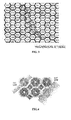
- FIG. 2 shows a possible mechanical stress affecting a localized portion of the monitored structure, the effects of which are sensed by a plurality of sensor cells belonging to the multi-cellular corollas of adjacently replicated monitoring devices of a bi-dimensional tablecloth array of surface monitoring devices of this disclosure.
- FIG. 3 is a map of highlighted sensor cells that are subjected to a change of their original electrically readable value; for example an integrated resistor subject to change value (e.g. increasing its resistance if stretched) because of the straining effect of the localized stress.
- the change of resistance of the affected sensor cells is detected by the respective core cells RFID to which the affected sensor cells pertain and these changes, read by a RFID surface reader device by scanning the monitored surface of the structure covered by the surface monitoring tablecloth device of the applicant, provide a map of the detected local stresses born by the monitored structure.
- FIG. 4 shows possible severing lines of a piece or strip of the monolithically fabricated ribbon of table cloth array of self consistent monitoring modules that, as depicted in FIG. 4 , may also have different shapes and sizes. Of course there will be individual modules that will be destroyed by cutting them through and the devices that would be lost are highlighted in the layout view.
- FIG. 5 is a layout view that illustrates a possible hierarchic architecture for surface data acquisition, according to which the number of RFID core cells to be accessed by an external reader device used for acquiring the data, highlighted in the layout view of FIG. 5 and denominated "active", may be greatly reduced.
- the active RFID core cells are eventually RF excited individually in a far-field mode by an external reader hovering or run over the surface sensing sheath for acquiring data not solely pertaining to the corolla sensor cells of the excited RFID core cell, but also to the corolla sensor cells pertaining to neighboring modules, the core cells of which, denominated RFID "passive", have a multi-bit storage resource embedded in their sensing circuitry and have a short-range, near-field RFID excitable tag antenna means adapted to communicate via electromagnetic or magnetic coupling with a dedicated short-range antenna of the active RFID core cell of the multi-module cluster for reading the data stored in the other modules of the cluster, making them acquirable by the far-field RF coupled external data acquisition reader device.
- transmission and acquisition of data sensed over an enlarged portion of a monitored surface through a centralization in a data acquisition point for a cluster of several multi-sensor surface monitoring devices may be implemented by implementing in the active RFID core cells and in neighboring passive RFID core cells composing an externally readable cluster, multi branch near-field RF antenna cascades as those described in prior published patent application US2009/0033467-A1 , of the same assignee and parallel filed new patent application No. VA2010A000089, filed on November 30, 2010 , the whole content of which is herein incorporated by reference.
- FIG. 6 shows a possible embodiment of an RFID passive monitoring device or module, wherein the corolla sensor cells are, for example, indicated as being integrated strain gauge sensors.
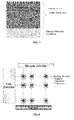
- the embedded storage means of the passive RFID core cell may have a memory map organized as depicted in FIG. 7 , with dedicated sensor memory locations, where the information-bearing content of each memory bit (a strain gauge sensor cell) may be determined, according to predefined thresholds that for the contemplated example of FIG. 6 , would be resistance values a resistor assumes when subject to stretching, alternatively the sensor could be a thermal resistor or any other parameter sensing device.
- the sensor memory of an RFID core cell may be programmed, after manufacturing, by exposing the sensing element to a certain magnitude of the monitored parameter.
- the programming process may be irreversible or even reversible and the memory locations may be one-time programmable or rewritable.
- the sensor memory access architecture may have a traditional scheme as illustrated in FIG. 8 .
- Large surface monitoring systems offer unique features of taylorability to needs in view of its tablecloth ribbon form it may be fabricated, flexibility and pliability to perfectly conform to the surface to be monitored, outstanding sturdiness because of its fabric supported substantially organic polymeric substrate of integration and inclusion of silicon based ICs of specific functional circuitry of relatively complex signal processing and data storage, interconnected with ancillary and/or peripheral organic polymer based circuitry.
Landscapes
- Engineering & Computer Science (AREA)
- Computer Hardware Design (AREA)
- Microelectronics & Electronic Packaging (AREA)
- Physics & Mathematics (AREA)
- General Physics & Mathematics (AREA)
- Theoretical Computer Science (AREA)
- Computer Networks & Wireless Communication (AREA)
- Arrangements For Transmission Of Measured Signals (AREA)
Abstract
A self consistent monitoring device comprises a core cell wirelessly RF identifiable and excitable comprising a tag antenna adapted to exchange data with a data acquisition reader device via electromagnetic or magnetic coupling of the tag antenna with an antenna of the reader device, a monolithically integrated circuit including al least a resonance capacitor, a modulator, a rectifier circuit, a charge-pump circuit, a detection circuit, logic and/or analog signal processing circuit, and at least a one tier corolla of identical or different sensor cells around said core cell, covering an area of a monitored structure or body onto which the multi-cellular monitoring device is applied that is a multiple of the individual surface area of a single sensor cell, all sensor cells adapted to convert a change of a geometrical, physical, or chemical parameter or state at the cell location, parameter change and location being detected by the detection circuit of the core cell, upon excitation by said reader device.
Generally, the self consistent monitoring device constitutes a unitary module that is replicated innumerable times over a flexible supporting cloth or plastic film, forming a bi-dimensional tablecloth array of identical or different monitoring devices each covering a certain surface area of a monitored structure or body.


Description
- The present disclosure relates generally to the monitoring of physical, chemical and/or geometrical parameters over large structures wherein it is necessary to monitor certain parameters in a "distributed" manner over extended areas of the structure.
- Prior patent application No.
VA2010A000018, filed on February 26, 2010 - Conductive boundary strips among the cells provides electrical paths of common supply rails and/or of input/output nodes of the cells.
- Self consistency of each individual cell follows the conventional approach of a pixel type organization and is burdensome specially for sensing events that may occur at any location over a relatively large surface of a structure or body to be monitored.
- Communication with the external board through optoelectronic devices as envisaged in said prior patent application limits its usefulness to applications wherein it is possible to optically read the cells. Moreover, incorporation of a battery or other energy storing device in each individual cell may be another burdensome aspect.
- A novel architecture has been found that overcomes the above discussed drawbacks of prior systems by devising self consistent monitoring devices (modules) that are replicable over a continuous flexible substrate preferably of organic polymeric constitution, eventually supported on a flexible ribbon that may be a textile fabric or a fiber-reinforced plastic film, substantially in a bi-dimensionally extending tablecloth-like array of identical or different devices (modules), each covering a relatively extended surface area of a monitored structure or body.
- Each self consistent monitoring device comprises a core cell including a monolithically integrated functional circuitry and RF coupling tag means including a tag antenna, integrated or formed onto the IC chip by post processing, adapted to make wirelessly RF identifiable and excitable the single module among the neighbour modules of the tablecloth array, and to exchange data with a reader device via a far-field or near-field electromagnetic coupling with an antenna of the reader device or via a far-field or near-field multiple electromagnetic or magnetic couplings, for example through concatenated electromagnetic expansions, in a substantially wireless manner with neighbor modules, or alternatively even with a wire connection to access terminals or pads arranged along one or more perimeter sides of the bi-dimensionally extended tablecloth array of self consistent surface monitoring modules.
- The core cell may be energized by rectifying a suitably concentrated RF electromagnetic energy transferred by the reader device upon coupling with the core cell to acquire data sensed by its corolla sensor cells or alternatively, have an embedded energy source in the form of a micro-battery or of a photovoltaic generation device eventually associated to a an embedded storage element, as disclosed in the already cited prior patent application No.
VA2010A000018 - The monolithically integrated functional circuitry of each core cell includes al least a resonance capacitor, a modulator, a rectifier circuit, a charge-pump circuit, a detection circuit and analog and logic signal processing circuits.
- Each self consistent monitoring device or module has at least a one tier corolla of identical or different sensor cells around said core cell, covering a substantially enlarged area of the surface of a monitored structure or body onto which the multi-cellular monitoring device is applied that is a multiple of the individual surface area of a single sensor cell of the corolla. Each sensor cell is adapted to convert a change of a geometrical, physical or chemical parameter or state at its location over the surface of the monitored structure or body, and any such change and location of occurrence is detected/recognized by the detection and signal processing circuit of the core cell, upon being RF excited by said reader device.
- The novel approach contemplates "monolithically" replicable units (monitoring devices) endowed with a geometrically ordered plurality of identical or different sensors cells that thus cover a proportionately extended area of the surface of the structure or body to be monitored, providing for the detection of parameter changes and their location of occurrence over the covered area of the singly readable unit. This, besides making a so composed monolithic unit (severed from tablecloth array magazine ribbon) usable per se to gather information on events and locations of occurrence over an extended area, makes the monitoring of vast surfaces significantly less burdensome by reducing the number of data acquisition nodes.
- The invention is defined in the annexed claims, the content of which is intended to be part of this description.
- The peculiarities of the article of manufacture of the present disclosure will now be highlighted in the following description of exemplary embodiments, making reference to the attached drawings, which is not to be intended as limiting the scope of the claimed invention to the examples, herein below illustrated for an easier comprehension of the invention.
-
-
FIG. 1 is an exemplary highlighted layout of a self consistent monitoring device of this disclosure. -
FIG. 2 shows a possible event of a localized stress over a surface sensed by a plurality of sensor cells belonging to the multi-cellular corollas of adjacently replicated monitoring devices of a bi-dimensional tablecloth array of surface monitoring devices. -
FIG. 3 is a map of highlighted sensor cells that are subjected to a change of their original electrically readable value consequent to the straining effect of the localized stress. -
FIG. 4 shows possible severing lines of a piece of the multi-device sheet and the devices that would be lost. -
FIG. 5 illustrates a scheme of hierarchic architecture of a distributed multi- RFID module surface sensing array of this disclosure. -
FIG. 6 is a layout illustration of an elementary surface monitoring device (module) wherein all the sensor cells of the corolla around the core cell are strain gauges for mapping mechanical stress over the sensed surface area. -
FIG. 7 is a graphical representation of the memory map adapted to store read bits according to a hierarchic access architecture ofFIG. 5 . -
FIG. 8 is an alternative memory architecture of an RFID surface sensor array of this disclosure. -
FIG. 1 is an exemplary highlighted layout of an elementary self consistent monitoring device (module) juxtaposedly replicable in a bi-dimensional tablecloth array in a substantially flexible all-organic multilayer polymer base monolithically in which the functional circuits of the device are monolithically integrated, eventually embedding also silicon-base integrated circuit chips functionally connected to the organic integrated circuit. - Materials and fabrication technologies may be those described in prior Italian patent applications no.
VA2008A000062 VA2010A000018 - The shape of the core cell RFID and of the corolla cells SENSOR may be of any geometric shape: polygonal, disc-like, oblong, etc. Cell shapes and arrangements that permit to enhance a close packing together of the sensing areas of the SENSOR cells and of these with the central core cell RFID are preferable.
- The size of the cells and thence of the unitary monitoring device (RFID+SENSORS) may be as small as allowed by the definition limits of the printing techniques used in the integration process if a fine granularity of surface sensing points is important for the intended surface monitoring application, or as large as desirable for applications wherein an extended coverage of relatively vast surfaces is a dominant requisite. Organic base cells may have sizes in the order of several centimeters, therefore a single replicable unitary monitoring device may cover an area of the surface of the monitored structure or body that may reach several decimeters square, within which the device is able to provide information on parameter changes and the locations within the covered area where the events take place.
- Optionally, each cell may shares in common with other cells or at least with cells of the same type, at least a conducting layer of constituting an electrical supply distribution rail or an input/output of the integrated circuit of the cells, allowing cells to function in parallel.
- The corolla sensing cells SENSOR may be structural sensors, corrosion sensors, accelerometers, inclinometers, moisture sensors, strain/crack gauges and others. They may be passive as certain structural sensors and inclinometers, strain/crack gauges, variable resistors, variable capacitors, or they may include active circuits, in which case the core RFID cell normally provide the required power supply to the active circuital components of the sensor cell circuit.
-
FIG. 2 shows a possible mechanical stress affecting a localized portion of the monitored structure, the effects of which are sensed by a plurality of sensor cells belonging to the multi-cellular corollas of adjacently replicated monitoring devices of a bi-dimensional tablecloth array of surface monitoring devices of this disclosure.FIG. 3 is a map of highlighted sensor cells that are subjected to a change of their original electrically readable value; for example an integrated resistor subject to change value (e.g. increasing its resistance if stretched) because of the straining effect of the localized stress. The change of resistance of the affected sensor cells (the highlighted SENSOR cells) is detected by the respective core cells RFID to which the affected sensor cells pertain and these changes, read by a RFID surface reader device by scanning the monitored surface of the structure covered by the surface monitoring tablecloth device of the applicant, provide a map of the detected local stresses born by the monitored structure. -
FIG. 4 shows possible severing lines of a piece or strip of the monolithically fabricated ribbon of table cloth array of self consistent monitoring modules that, as depicted inFIG. 4 , may also have different shapes and sizes. Of course there will be individual modules that will be destroyed by cutting them through and the devices that would be lost are highlighted in the layout view. - Overall burdensomeness of the surface monitoring structure may be reduced by implementing more efficient access schemes to the sensed information.
FIG. 5 is a layout view that illustrates a possible hierarchic architecture for surface data acquisition, according to which the number of RFID core cells to be accessed by an external reader device used for acquiring the data, highlighted in the layout view ofFIG. 5 and denominated "active", may be greatly reduced. According to such an embodiment, the active RFID core cells are eventually RF excited individually in a far-field mode by an external reader hovering or run over the surface sensing sheath for acquiring data not solely pertaining to the corolla sensor cells of the excited RFID core cell, but also to the corolla sensor cells pertaining to neighboring modules, the core cells of which, denominated RFID "passive", have a multi-bit storage resource embedded in their sensing circuitry and have a short-range, near-field RFID excitable tag antenna means adapted to communicate via electromagnetic or magnetic coupling with a dedicated short-range antenna of the active RFID core cell of the multi-module cluster for reading the data stored in the other modules of the cluster, making them acquirable by the far-field RF coupled external data acquisition reader device. - For example, transmission and acquisition of data sensed over an enlarged portion of a monitored surface through a centralization in a data acquisition point for a cluster of several multi-sensor surface monitoring devices (modules) may be implemented by implementing in the active RFID core cells and in neighboring passive RFID core cells composing an externally readable cluster, multi branch near-field RF antenna cascades as those described in prior published patent application
US2009/0033467-A1 , of the same assignee and parallel filed new patent application No.VA2010A000089, filed on November 30, 2010 -
FIG. 6 shows a possible embodiment of an RFID passive monitoring device or module, wherein the corolla sensor cells are, for example, indicated as being integrated strain gauge sensors. Accordingly, the embedded storage means of the passive RFID core cell may have a memory map organized as depicted inFIG. 7 , with dedicated sensor memory locations, where the information-bearing content of each memory bit (a strain gauge sensor cell) may be determined, according to predefined thresholds that for the contemplated example ofFIG. 6 , would be resistance values a resistor assumes when subject to stretching, alternatively the sensor could be a thermal resistor or any other parameter sensing device. - The sensor memory of an RFID core cell may be programmed, after manufacturing, by exposing the sensing element to a certain magnitude of the monitored parameter. The programming process may be irreversible or even reversible and the memory locations may be one-time programmable or rewritable.
- The sensor memory access architecture may have a traditional scheme as illustrated in
FIG. 8 . - Large surface monitoring systems according to the present disclosure offer unique features of taylorability to needs in view of its tablecloth ribbon form it may be fabricated, flexibility and pliability to perfectly conform to the surface to be monitored, outstanding sturdiness because of its fabric supported substantially organic polymeric substrate of integration and inclusion of silicon based ICs of specific functional circuitry of relatively complex signal processing and data storage, interconnected with ancillary and/or peripheral organic polymer based circuitry.
- Contemplated fields of application may include:
- buildings, bridges, big infrastructures monitoring (Structural Health Monitoring);
- airplane structural monitoring;
- gas and oil tanks and tankers crack monitoring;
- large area pollution monitoring;
- passenger collision detection systems and smart passenger compartment surfaces in automotive environment;
- works of art, monuments aging monitoring.
Claims (6)
- A self consistent monitoring device comprising:a) a far field or near field identifiable and excitable core cell comprising RF coupling means including tag antenna means adapted to exchange data with a data acquisition reader device via electromagnetic or magnetic coupling of the tag antenna with an antenna of the reader device;b) a monolithically integrated circuit including al least a resonance capacitor, a modulator, a rectifier circuit, a charge-pump circuit, a detection circuit, logic and/or analog signal processing circuit;c) at least a one tier corolla of identical or different sensor cells around said core cell, covering an area of a monitored structure or body onto which the multi-cellular monitoring device is applied that is a multiple of the individual surface area of a single sensor cell, all sensor cells adapted to convert a change of a geometrical, physical, or chemical parameter or state at the cell location, parameter change and location being detected by said detection circuit of the core cell, upon excitation by said reader device.
- The self consistent monitoring device of claim 1, constituting a unitary module replicated innumerable times over a flexible supporting cloth or plastic film forming a bi-dimensional tablecloth array of identical monitoring devices each covering a certain surface area of a monitored structure or body.
- The self consistent monitoring device of claim 1, wherein said sensor cells include active devices powered by said charge-pump circuit of the core cell via electrically conductive rails common to all the cells.
- The self consistent monitoring device of claim 1, wherein said sensor cells include active devices powered via near-field RF wireless coupling of each sensor cell provided with or magnetic coupling means with electromagnetic or magnetic coupling means of the core cell.
- The self consistent monitoring device of claim 1 and 2, wherein each or some of the core cells of the self consistent monitoring devices have an embedded energy source in form of a battery or photovoltaic generator.
- A bi-dimensional tablecloth array of identical self consistent monitoring devices of claim 1, wherein clusters of neighboring monitoring devices comprise a central device with far-field RF identifiable and excitable core cell that besides comprising said tag antenna adapted to exchange data with a reader device via electromagnetic or magnetic coupling of the tag antenna with an antenna of the reader device, has at least another antenna;
the core cells of all other neighboring monitoring devices have a multi-bit data storage resource embedded in their sensing circuitry and a short-range, near-field RF identifiable and excitable tag antenna, adapted to communicate via electromagnetic or magnetic coupling with said other antenna of the core cell of said central device adapted to reading the sensed data stored in the multi-bit data storage resource of each of said neighboring monitoring devices of the cluster, making them acquirable by a far-field RF coupled data acquisition reader device.
Applications Claiming Priority (1)
| Application Number | Priority Date | Filing Date | Title |
|---|---|---|---|
| ITVA20100090 | 2010-11-30 |
Publications (1)
| Publication Number | Publication Date |
|---|---|
| EP2458529A1 true EP2458529A1 (en) | 2012-05-30 |
Family
ID=43743166
Family Applications (1)
| Application Number | Title | Priority Date | Filing Date |
|---|---|---|---|
| EP11191126A Withdrawn EP2458529A1 (en) | 2010-11-30 | 2011-11-29 | Large area monitoring device |
Country Status (2)
| Country | Link |
|---|---|
| US (1) | US8459554B2 (en) |
| EP (1) | EP2458529A1 (en) |
Families Citing this family (3)
| Publication number | Priority date | Publication date | Assignee | Title |
|---|---|---|---|---|
| IT1403044B1 (en) * | 2010-11-30 | 2013-09-27 | St Microelectronics Srl | RFID READABLE DEVICE WITH SMART SURFACE ACCESS. |
| ITTO20120633A1 (en) | 2012-07-18 | 2014-01-19 | St Microelectronics Srl | SENSOR FOR PRESSURE MEASUREMENTS |
| CN115753998B (en) * | 2022-12-07 | 2024-08-27 | 大连理工大学 | Method and system for monitoring aircraft composite material structural damage in service environment |
Citations (3)
| Publication number | Priority date | Publication date | Assignee | Title |
|---|---|---|---|---|
| US20090033467A1 (en) | 2007-07-30 | 2009-02-05 | Stmicroelectronics S.R.L. | Rf identification device with near-field-coupled antenna |
| US20100231407A1 (en) * | 2009-03-13 | 2010-09-16 | New Jersey Microsystems, Inc. | RFID power control and monitoring system |
| US20100236598A1 (en) * | 2009-03-18 | 2010-09-23 | Solar Semiconductor Pvt. Ltd. | Embedded rfid solution for solar panels |
Family Cites Families (6)
| Publication number | Priority date | Publication date | Assignee | Title |
|---|---|---|---|---|
| US4816665A (en) * | 1987-08-06 | 1989-03-28 | Maxtor Corporation | Sensor array for focus detection |
| WO2002089038A2 (en) * | 2001-04-27 | 2002-11-07 | Atrua Technologies, Inc. | Capacitive sensor system with improved capacitance measuring sensitivity |
| US6935169B2 (en) * | 2002-10-28 | 2005-08-30 | Delphi Technologies, Inc. | Tire pressure sensor array |
| IT1392321B1 (en) | 2008-12-15 | 2012-02-24 | St Microelectronics Srl | SENSOR / ACTUATOR SYSTEM ENTIRELY IN ORGANIC MATERIAL |
| BR112012003078A2 (en) * | 2009-08-17 | 2019-09-24 | Univ California | interrogable external sensor system for obtaining one or more biological characteristics of a patient's body internal tissue surface or region, method for obtaining one or more biological characteristics of a patient's internal tissue surface or region, transdermal sensor system for obtaining one or more biological characteristics of a patient's internal tissue region, method for obtaining one or more biological characteristics of a patient's internal tissue region, and interrogable sensor system for obtaining one or more biological characteristics of an internal tissue region of a patient |
| EP2362421A1 (en) | 2010-02-26 | 2011-08-31 | STMicroelectronics S.r.l. | Tailorable flexible sheet of monolithically fabricated array of separable cells each comprising a wholly organic, integrated circuit adapted to perform a specific function |
-
2011
- 2011-09-22 US US13/240,606 patent/US8459554B2/en not_active Expired - Fee Related
- 2011-11-29 EP EP11191126A patent/EP2458529A1/en not_active Withdrawn
Patent Citations (3)
| Publication number | Priority date | Publication date | Assignee | Title |
|---|---|---|---|---|
| US20090033467A1 (en) | 2007-07-30 | 2009-02-05 | Stmicroelectronics S.R.L. | Rf identification device with near-field-coupled antenna |
| US20100231407A1 (en) * | 2009-03-13 | 2010-09-16 | New Jersey Microsystems, Inc. | RFID power control and monitoring system |
| US20100236598A1 (en) * | 2009-03-18 | 2010-09-23 | Solar Semiconductor Pvt. Ltd. | Embedded rfid solution for solar panels |
Also Published As
| Publication number | Publication date |
|---|---|
| US8459554B2 (en) | 2013-06-11 |
| US20120132711A1 (en) | 2012-05-31 |
Similar Documents
| Publication | Publication Date | Title |
|---|---|---|
| ES2330336T3 (en) | MANUFACTURING PROCEDURE OF A CARD ANTENNA WITH CHIP ON A THERMOPLASTIC SUPPORT AND CARD WITH CHIP ASI OBTAINED. | |
| US7969364B2 (en) | Radio frequency device and method of manufacture | |
| CN101384186B (en) | A structure of fabric and electronic components | |
| US20110220182A1 (en) | Solar Panel Tracking and Performance Monitoring Through Wireless Communication | |
| KR102486316B1 (en) | deformable sensor | |
| EP3754316B1 (en) | Design and fabrication of high density sensor array | |
| US8459554B2 (en) | Large area monitoring device | |
| CN103765447B (en) | Contact-contactless hybrid IC card with ruggedized electronic module | |
| EP1678473A1 (en) | Sensor and sensor array for monitoring a structure | |
| US20110095891A1 (en) | Product and electronic tag assembly | |
| US20100236598A1 (en) | Embedded rfid solution for solar panels | |
| US8558707B1 (en) | Thermal cutoff fuse for arbitrary temperatures | |
| US8154410B2 (en) | Radio frequency tag and method for manufacturing radio frequency tag | |
| BR112020013124A2 (en) | rfid tags using multilayer constructions for improved durability | |
| Unander et al. | Designing of RFID-based sensor solution for packaging surveillance applications | |
| KR102787177B1 (en) | Battery module and temperature measurement method thereof | |
| Weber et al. | Electronics in textiles the next stage in man machine interaction | |
| US20020090800A1 (en) | Electronic apparatus and manufacturing method for an electronic apparatus | |
| US7956759B1 (en) | Humidity sensitive cutoff fuse | |
| US8981792B2 (en) | RFID readable device with smart surface access | |
| EP4475034A1 (en) | Sensor tag and storing container with such a sensor tag | |
| US8184009B1 (en) | Humidity-sensitive cutoff fuse | |
| JP5078639B2 (en) | IC product management system | |
| CN204695355U (en) | A kind of RFID smart card | |
| JP2007026145A (en) | Non-contact type data carrier device |
Legal Events
| Date | Code | Title | Description |
|---|---|---|---|
| PUAI | Public reference made under article 153(3) epc to a published international application that has entered the european phase |
Free format text: ORIGINAL CODE: 0009012 |
|
| AK | Designated contracting states |
Kind code of ref document: A1 Designated state(s): AL AT BE BG CH CY CZ DE DK EE ES FI FR GB GR HR HU IE IS IT LI LT LU LV MC MK MT NL NO PL PT RO RS SE SI SK SM TR |
|
| AX | Request for extension of the european patent |
Extension state: BA ME |
|
| 17P | Request for examination filed |
Effective date: 20121030 |
|
| STAA | Information on the status of an ep patent application or granted ep patent |
Free format text: STATUS: THE APPLICATION HAS BEEN WITHDRAWN |
|
| 18W | Application withdrawn |
Effective date: 20140708 |