EP2458258B1 - Weighted mounting arrangement for steadily supporting a motion-sensitive, image capture device - Google Patents
Weighted mounting arrangement for steadily supporting a motion-sensitive, image capture device Download PDFInfo
- Publication number
- EP2458258B1 EP2458258B1 EP11190797.8A EP11190797A EP2458258B1 EP 2458258 B1 EP2458258 B1 EP 2458258B1 EP 11190797 A EP11190797 A EP 11190797A EP 2458258 B1 EP2458258 B1 EP 2458258B1
- Authority
- EP
- European Patent Office
- Prior art keywords
- mount
- image capture
- holder
- assembly
- mounting arrangement
- Prior art date
- Legal status (The legal status is an assumption and is not a legal conclusion. Google has not performed a legal analysis and makes no representation as to the accuracy of the status listed.)
- Not-in-force
Links
Images


Classifications
-
- F—MECHANICAL ENGINEERING; LIGHTING; HEATING; WEAPONS; BLASTING
- F16—ENGINEERING ELEMENTS AND UNITS; GENERAL MEASURES FOR PRODUCING AND MAINTAINING EFFECTIVE FUNCTIONING OF MACHINES OR INSTALLATIONS; THERMAL INSULATION IN GENERAL
- F16M—FRAMES, CASINGS OR BEDS OF ENGINES, MACHINES OR APPARATUS, NOT SPECIFIC TO ENGINES, MACHINES OR APPARATUS PROVIDED FOR ELSEWHERE; STANDS; SUPPORTS
- F16M11/00—Stands or trestles as supports for apparatus or articles placed thereon Stands for scientific apparatus such as gravitational force meters
- F16M11/02—Heads
- F16M11/04—Means for attachment of apparatus; Means allowing adjustment of the apparatus relatively to the stand
- F16M11/041—Allowing quick release of the apparatus
-
- F—MECHANICAL ENGINEERING; LIGHTING; HEATING; WEAPONS; BLASTING
- F16—ENGINEERING ELEMENTS AND UNITS; GENERAL MEASURES FOR PRODUCING AND MAINTAINING EFFECTIVE FUNCTIONING OF MACHINES OR INSTALLATIONS; THERMAL INSULATION IN GENERAL
- F16M—FRAMES, CASINGS OR BEDS OF ENGINES, MACHINES OR APPARATUS, NOT SPECIFIC TO ENGINES, MACHINES OR APPARATUS PROVIDED FOR ELSEWHERE; STANDS; SUPPORTS
- F16M13/00—Other supports for positioning apparatus or articles; Means for steadying hand-held apparatus or articles
- F16M13/02—Other supports for positioning apparatus or articles; Means for steadying hand-held apparatus or articles for supporting on, or attaching to, an object, e.g. tree, gate, window-frame, cycle
-
- F—MECHANICAL ENGINEERING; LIGHTING; HEATING; WEAPONS; BLASTING
- F16—ENGINEERING ELEMENTS AND UNITS; GENERAL MEASURES FOR PRODUCING AND MAINTAINING EFFECTIVE FUNCTIONING OF MACHINES OR INSTALLATIONS; THERMAL INSULATION IN GENERAL
- F16M—FRAMES, CASINGS OR BEDS OF ENGINES, MACHINES OR APPARATUS, NOT SPECIFIC TO ENGINES, MACHINES OR APPARATUS PROVIDED FOR ELSEWHERE; STANDS; SUPPORTS
- F16M13/00—Other supports for positioning apparatus or articles; Means for steadying hand-held apparatus or articles
- F16M13/04—Other supports for positioning apparatus or articles; Means for steadying hand-held apparatus or articles for supporting on, or holding steady relative to, a person, e.g. by chains, e.g. rifle butt or pistol grip supports, supports attached to the chest or head
-
- H—ELECTRICITY
- H04—ELECTRIC COMMUNICATION TECHNIQUE
- H04M—TELEPHONIC COMMUNICATION
- H04M1/00—Substation equipment, e.g. for use by subscribers
- H04M1/02—Constructional features of telephone sets
- H04M1/04—Supports for telephone transmitters or receivers
-
- F—MECHANICAL ENGINEERING; LIGHTING; HEATING; WEAPONS; BLASTING
- F16—ENGINEERING ELEMENTS AND UNITS; GENERAL MEASURES FOR PRODUCING AND MAINTAINING EFFECTIVE FUNCTIONING OF MACHINES OR INSTALLATIONS; THERMAL INSULATION IN GENERAL
- F16M—FRAMES, CASINGS OR BEDS OF ENGINES, MACHINES OR APPARATUS, NOT SPECIFIC TO ENGINES, MACHINES OR APPARATUS PROVIDED FOR ELSEWHERE; STANDS; SUPPORTS
- F16M2200/00—Details of stands or supports
- F16M2200/04—Balancing means
- F16M2200/041—Balancing means for balancing rotational movement of the head
Definitions
- This invention generally relates to a weighted mounting arrangement for steadily supporting motion-sensitive, image capture devices, such as stand-alone image capture devices, e.g., ultra-lightweight cameras, web cameras and camcorders, as well as other multiple use devices, such as cellular telephones, personal digital assistants, media players, game controllers, and like devices in which image capture capability has been incorporated and, more particularly, relates to isolating all such devices from unwanted motion during image capture.
- image capture devices such as stand-alone image capture devices, e.g., ultra-lightweight cameras, web cameras and camcorders
- other multiple use devices such as cellular telephones, personal digital assistants, media players, game controllers, and like devices in which image capture capability has been incorporated and, more particularly, relates to isolating all such devices from unwanted motion during image capture.
- Still picture and motion picture (video) cameras have, at some time during their use, been handheld by a human operator whose inherent instability tended to produce blurred still and moving images.
- ultra-lightweight cameras such as web cameras weighing less than one pound
- the current ultra-lightweight cameras are so compact and light that they have even been incorporated into other multiple use devices, such as cellular telephones, personal digital assistants, media players, game controllers and like handheld devices.
- these handheld devices were being operated by amateur photographers, still further resulting in unstable and often unacceptable still and video images, especially during ambulatory operation.
- Some handheld devices have been equipped with global positioning systems, and have been mounted in/on vehicles or other forms of transportation by adjustable mechanisms that allow the handheld devices to be desirably positioned along one or more axes relative to a mounting platform for convenient operation by, or orientation that faces, the user.
- adjustable mechanisms typically incorporated a positionable tripod mount, a semi-rigid bendable gooseneck mount, a ball end swivel mount, or other types of multi-jointed or adjustable mechanism that was connected between the handheld device and the mounting platform.
- adjustable mechanisms As desirable as such adjustable mechanisms have been in non-image capture applications, they are not well suited for image capture applications.
- the known adjustable mechanisms lacked the capability to rigidly fix and fixedly orient an image plane of the handheld device perpendicularly to the mounting platform. If the image plane was not perpendicular to the mounting platform, then an equipoising support would need to be operated at an undesirable off-axis orientation in order to obtain straight on or level images.
- level indicators would not be accurate with respect to the orientation of the image to be acquired.
- Existing multi-jointed or adjustable mechanisms have been prone to movement or vibration due to the flexible, movable nature of the multi-part construction. Such potential vibration or movement of the orientation of the device was detrimental to stable image capture, especially when the device was in motion or subjected to external forces, such as wind.
- the known adjustable mechanisms i.e. WO 2010/078575 have failed to effectively and satisfactorily eliminate the problems of instability encountered in connection with operation of the ever-lighter, digital, still and motion, cameras that have been developed, and it therefore is desirable to furnish a stabilized mounting arrangement particularly well suited to the special requirements of ultra-lightweight, handheld, digital devices, particularly consumer-operated video cameras and like devices, e.g., those incorporated into cellular telephones, personal digital assistants, media players, game controllers, and like handheld devices in which image capture capability has been incorporated.
- One aspect of this invention is directed to a mounting arrangement for steadily and stably supporting a motion-sensitive, image capture device on a support, preferably an equipoising handheld structure.
- the device is operative for capturing an image over a field of view along an optical axis perpendicular to an image plane.
- the device may be a stand-alone image capture device, e.g., an ultra-lightweight camera, a web camera, a camcorder, etc., or may be a multiple use device, such as a cellular telephone, a personal digital assistant, a media player, a game controller, and like devices in which image capture capability has been incorporated.
- the mounting arrangement as defined in claim 1 includes a mount having a holder for holding the device during image capture, and a fixed base integral with, or connected to, the holder.
- the base is immovable relative to the holder and has a bottom surface that lays in a base plane perpendicular to the image plane when the base is supported by the support in a supported orientation.
- the base is operative for steadily positioning the holder and the device on the support in the supported orientation during the image capture.
- the capability of rigidly fixing the orientation or image plane of the handheld device with respect to the support avoids the capture of blurry images.
- the holder has a plurality of arms for detachably gripping a periphery of the device.
- the arms are constituted of a resilient material, such as synthetic plastic or metal.
- the arms are spaced away from, and do not block, the field of view, or interfere with any functions of the device, i.e., buttons, connector ports, battery replacement.
- the holder may be customized to hold one or more similar physical models of the device.
- the base is advantageously provided with an insert having an internally threaded passage for threaded engagement with an externally threaded stud extending away from the support in the supported orientation during the image capture.
- the stud is preferably an industry standard 1 ⁇ 4 inch-20 threaded mounting stud to enable the mount to be readily mounted on industry standard camera and video equipment mounting platforms, such as tripods and/or handheld equipoising supports.
- the base is also advantageously provided with an anti-rotation index hole for receiving an index pin extending away from the support in the supported orientation during the image capture.
- This feature insures that the handheld device is mounted and maintained without rotation in the correct orientation with respect to the camera mounting equipment. Unwanted rotation or movement of the handheld device during abrupt movements or re-positioning of the equipment is prevented.
- the holder and the base may, but need not, be mirror symmetrical relative to a central plane.
- the insert and the index hole preferably lay in the central plane.
- the holder may also be designed such that it is off axis with respect to the base to accommodate special mounting requirements, or to align the optical centerline of the image capture device to the geometrical centerline of the mount.
- the holder is provided with one or more integral weights for balance.
- a ballast weight is commonly mounted on the mount with the held device.
- the ballast weight, the mount and the held device together constitute an assembly having a total assembly weight at a center of gravity that is preferably offset from a geometric center of the mount.
- the assembly and the equipoising structure together have a combined center of gravity that is positioned in close adjacent proximity below the handle connection for balancing the arrangement during image capture.
- the handle is pivotably connected at a pivot axis to the platform, and the combined center of gravity is positioned about one-sixteenth of an inch or less vertically below the pivot axis.
- the balanced mounting arrangement supports the device in a low mass, compact mounting profile. Without this capability, the mounting of the handheld device might prove difficult if it were used in conjunction with existing camera mounting equipment, such as environmental camera enclosures, SLR-type camera flash brackets, and the like. Tall mounts that are high in profile may also not be able to be balanced properly on equipoising support structures.
- the handheld devices are rigidly supported with balance such that the images that they capture are stable and free from unwanted movement or vibration while the image is being acquired.
- Readily available industrial equipment can be used to help stabilize and/or manipulate the handheld devices.
- FIG. 1 is a front perspective view of one example not forming part of the claimed invention of a stabilized mount in which a multiple use, handheld device is held;
- FIG. 2 is a rear perspective view of the stabilized mount of FIG. 1 in which the device is held;
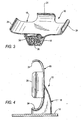
- FIG. 3 is a front perspective view of the stabilized mount of FIG. 1 without the device;
- FIG. 4 is an upright side elevational view of the stabilized mount of FIG. 1 without the device;
- FIG. 5 is a reduced-scale, broken-away, perspective view of the stabilized mount of FIG. 1 on a tripod;
- FIG. 6 is a perspective view of a detail of FIG. 5 ;
- FIG. 7 is a reduced-scale, perspective view of the stabilized mount of FIG. 1 on an equipoising support structure
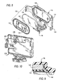
- FIG. 8 is an exploded, perspective view of an embodiment of a stabilized weighted mount in which a multiple use, handheld device is held in an assembly in accordance with this invention
- FIG. 9 is an enlarged sectional view of a detail of FIG. 8 ;
- FIG. 10 is an exploded, perspective view of another embodiment of a stabilized weighted mount in accordance with this invention.
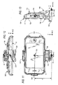
- FIG. 11 is a front elevational view of the assembly of FIG. 8 depicting the location of the center of gravity of the assembly;
- FIG. 12 is a top plan view of FIG. 11 ;
- FIG. 13 is a right side elevational view of FIG. 11 ;
- FIG. 14 is a left side elevational view of a stabilized weighted mounting arrangement in which the assembly of FIG. 8 is mounted on an equipoising support structure, and depicting a combined center of gravity of the overall arrangement;
- FIG. 15 is a right side elevational view of FIG. 14 .
- reference numeral 10 generally identifies a stabilized mount of a mounting arrangement for steadily and stably supporting a motion-sensitive, image capture device 12 on a support 14 (see FIGS. 4-7 ).
- the device 12 is operative for capturing an image over a field of view along an optical axis perpendicular to an image plane.
- the device 12 may be a stand-alone image capture device, e.g., an ultra-lightweight camera, a web camera, a camcorder, etc., or may be a multiple use device, such as a cellular telephone, a personal digital assistant, a media player, a game controller, and like devices in which image capture capability has been incorporated.
- the support 14 is preferably a handheld equipoising structure ( FIGS. 7 , 14 and 15 ), but may be a tripod ( FIG. 5 ), or a table or countertop ( FIG. 4 ).
- the device 12 is an iPhone, which is a multimedia smartphone marketed by Apple, Inc.
- This device 12 has an internal solid-state imager having a two-dimensional array of cells or photosensors arranged in the image plane.
- the photosensors correspond to image elements or pixels in a field of view of the imager.
- the imager may be a charge coupled device (CCD) or a complementary metal oxide semiconductor (CMOS) device, together with associated bandpass spectral filters and electronic circuits for producing electrical signals corresponding to a two- dimensional array of pixel information over the field of view.
- This device 12 also has a viewfinder display 20 that is parallel to the image plane, as well as an aperture 22 (see FIG. 2 ) through which light passes to the imager.
- the mount 10 includes a holder 16 for holding the device 12 during image capture, and a fixed base 18 integral with, or connected to, the holder 16.
- the base 18 is immovable relative to the holder 16 and has a bottom surface that lays in a base plane perpendicular to the image plane when the base 18 is supported by the support 14 in a supported orientation.
- the base 18 is operative for steadily positioning the holder 16 and the device 12 on the support 14 in the supported orientation during the image capture.
- the capability of rigidly fixing the orientation or image plane of the handheld device 12 with respect to the support 14 avoids the capture of blurry images.
- the holder 16 has a plurality of four arms 24 for detachably gripping a periphery of the device 12.
- the arms 24 grip upper, lower and opposite side edges of the device 12 and clamp the device 12 in place.
- the arms 24 are curved at their ends and are constituted of a resilient material, such as synthetic plastic or metal, that yield to enable the device 12 to be snap-fitted to the holder 16.
- the arms 24 are spaced away from the aperture 22, and do not block or obstruct the field of view, or interfere with any functions of the device 12, e.g., buttons, connector ports, battery replacement.
- the holder 16 may be customized to hold one or more similar physical models of the device 12, or may be adapted to hold a plurality of different devices 12.
- the customized mount 10 can be sold separately from, or in conjunction with, a specific model of the device 12.
- the holder 16 may be provided with one or more integral weights for balance, as described below in connection with FIGS. 8-15 .
- the base 18 is advantageously provided with an insert 26 having an internally threaded passage for threaded engagement with an externally threaded stud 28 (see FIG. 6 ) extending away from the support 14 in the supported orientation during the image capture.
- the stud 28 is preferably an industry standard 1 ⁇ 4 inch-20 threaded mounting stud to enable the mount 10 to be readily mounted on industry standard camera and video equipment mounting platforms, such as tripods 30 (see FIG. 5 ) and/or equipoising support structures 32 (see FIGS. 7 , 14 and 15 ).
- the base 18 is also advantageously provided with an anti-rotation index hole 34 for receiving an index pin 36 (see FIG. 6 ) extending away from the support 14 in the supported orientation during the image capture.
- This feature insures that the handheld device 12 is mounted and maintained without rotation in the correct orientation with respect to the camera mounting equipment 30, 32. Unwanted rotation or movement of the handheld device 12 during abrupt movements or re-positioning of the equipment 30, 32 is prevented.
- the holder 16 and the base 18 are illustrated as, but need not be, mirror symmetrical relative to a central plane, and the insert 26 and the index hole 34 preferably lay in the central plane.
- the insert 26 and the index hole 34 are mutually arranged in a predetermined relationship that matches that of the stud 28 and the index pin 36.
- the holder 16 may also be designed such that it is off axis with respect to the base 18 to accommodate special mounting requirements, or to align the optical centerline of the device 12 to the geometrical centerline of the mount 10.
- the mount 10 supports the device 12 as an assembly in a low mass, compact mounting profile. Without this capability, the mounting of the handheld device 12 might prove difficult if it were used in conjunction with existing camera mounting equipment, such as environmental camera enclosures, SLR-type camera flash brackets, and the like. Tall mounts that are high in profile may also not be able to be balanced properly on equipoising support structures.
- FIG. 8 depicts an embodiment of a stabilized mount 100, similar to mount 10, and includes a holder 116 for holding the device 12 as an assembly during image capture, and a fixed base 118 integral with, or connected to, the holder 116.
- the holder 116 has a plurality of five arms 124 for detachably gripping a periphery of the device 12.
- the arms 124 grip upper, lower and opposite side edges of the device 12 and clamp the device 12 in place.
- the arms 124 are curved at their ends and are constituted of a resilient material, such as synthetic plastic or metal, that yield to enable the device 12 to be snap-fitted to the holder 116 by snap action.
- the arms 124 do not block or obstruct the field of view, or interfere with any functions of the device 12, e.g., buttons, connector ports, battery replacement.
- the base 118 is advantageously provided with an insert, analogous to the insert 26 having an internally threaded passage, and an anti-rotation index hole, analogous to the anti-rotation index hole 34.
- the holder 116 is formed with a cavity 138 in which at least one ballast weight 140 is accommodated.
- a cover 142 overlies the ballast weight 140 and, as shown in FIG. 9 , the cover 142 is ultrasonically welded at region 146 to the holder 116, or is mounted in the cavity 138 by snap action or by a fastener.
- the cavity 138 and the ballast weight 140 are of complementary contour. Additional ballast weights can be used.
- the cover 142 bears a graphic 144 that instructs a user how to correctly align and position the device 12 relative to the holder 116.
- the holder 116 is customized to hold a single physical model of the device 12.
- FIG. 10 still another embodiment of a stabilized mount, similar to mount 10, includes a holder 216 customized to hold a single physical model of a different image capture device as an assembly.
- the holder 216 is formed with a cavity 238 in which at least one ballast weight 240 is accommodated.
- the weight 240 has a pair of mounting holes that align with mounting posts in the cavity 238.
- a cover may overlie the weight 240.
- Different image capture devices 12 e.g., smartphones have different configurations and different weights and weight distributions. When such devices 12 are held in their respective different holders, their total assembly weights and weight distributions are also different, and they have different centers of gravity (mass). If it is desired to interchangeably mount such differently held devices on the same support, such as the handheld equipoising support structure 132 depicted in FIGS. 14 and 15 , then the centers of gravity of such differently held devices must be precisely located such that the combined center of gravity of the overall arrangement is precisely positioned at a specific location for proper balance. As explained below, this specific location is in close adjacent proximity below a handle connection at which a handle is connected to a platform of the equipoising support structure 132.
- the handle is pivotably connected at a pivot axis to the platform, and the combined center of gravity is positioned about one-sixteenth of an inch or less vertically below the pivot axis.
- the different weights and placement of the ballast weights 140 and 240 in FIGS. 8 and 10 represent one way to locate the centers of gravity of such differently held devices.
- the graphic 144 on the cover 142 represents another way to control the weight distribution by insuring that the device 12 is always positioned in the same orientation on its holder.
- FIGS. 11-13 depict the assembly of the device 12 held in the holder 116. Coordinate X, Y, Z axes are shown in each figure. For ease of reference, the bottommost, rearmost, central point on the assembly is identified as a reference point R. The center of gravity CG of the assembly is shown in each figure relative to the reference point R. The displacement X along the X-axis, the displacement Y along the Y-axis, and the displacement Z along the Z-axis are separately shown relative to the reference point R. It will be noted that the center of gravity CG of the assembly is not located at the geometrical center of the mount. Thus, the position of the center of gravity CG of the assembly is a fixed, known location and, as described above, the total weight of the assembly at that center of gravity CG is also fixed and known.
- FIGS. 14-15 depict the aforementioned handheld equipoising support structure 132 having a platform 150, a curved arm 152 having a large radius of curvature, a bottom counterweight 154, and a handle connector 156.
- a handle for gripping by a user is not illustrated to simplify the drawings, but it will be understood that the handle is pivotably connected to the platform 150 via the connector 156 at a pivot axis. Coordinate X, Y, Z axes are shown in each figure.
- the center of gravity of the equipoising support structure 132 by itself is well below the platform 150, e.g., about midway between the platform 150 and the bottom counterweight 154.
- the combined center of gravity P of the assembly and the equipoising support structure 132 is raised toward the platform 150.
- the known position of the center of gravity CG of the assembly and the known weight distribution of the assembly are selected so as to position the combined center of gravity P in close adjacent proximity below the handle connection or pivot axis, as shown.
- the combined center of gravity P is positioned about one-sixteenth of an inch or less vertically below the pivot axis or vertical balance point of the arrangement.
- the combined center of gravity P lies along, i.e., is coincident with, the Y-axis, and is not displaced along the X-axis or the Z-axis for proper balance.
- the bottom counterweight 154 may tend to swing the arrangement as a pendulum during rapid hand movement by an operator. Should a different assembly, e.g., a different device held in the mount of FIG. 10 , be mounted on the equipoising support structure 132, then proper balance is again assured due to the advance known positioning and known weight distribution of its center of gravity CG.
Description
- This invention generally relates to a weighted mounting arrangement for steadily supporting motion-sensitive, image capture devices, such as stand-alone image capture devices, e.g., ultra-lightweight cameras, web cameras and camcorders, as well as other multiple use devices, such as cellular telephones, personal digital assistants, media players, game controllers, and like devices in which image capture capability has been incorporated and, more particularly, relates to isolating all such devices from unwanted motion during image capture.
- Still picture and motion picture (video) cameras have, at some time during their use, been handheld by a human operator whose inherent instability tended to produce blurred still and moving images. In recent years, ultra-lightweight cameras, such as web cameras weighing less than one pound, have been developed, and the current ultra-lightweight cameras are so compact and light that they have even been incorporated into other multiple use devices, such as cellular telephones, personal digital assistants, media players, game controllers and like handheld devices. In addition to the traditional unsteadiness of a handheld camera, these handheld devices were being operated by amateur photographers, still further resulting in unstable and often unacceptable still and video images, especially during ambulatory operation.
- With the increasing popularity of handheld cellular telephones with built-in still and video image capture capability, it has become more and more desirable to rigidly support such handheld devices so that the images that they capture are stable and free from unwanted movement or vibration while the image is being acquired. Yet, the known handheld devices have not been directly integrated with the capability for such devices to be mounted onto industry standard camera and video equipment mounting platforms, such as tripods and/or equipoising supports. Hence, this readily available industrial equipment cannot be used to help stabilize and/or manipulate the handheld devices.
- Current methods of holding/mounting such handheld devices have been geared towards non-image capture applications. For example, some handheld devices have been equipped with global positioning systems, and have been mounted in/on vehicles or other forms of transportation by adjustable mechanisms that allow the handheld devices to be desirably positioned along one or more axes relative to a mounting platform for convenient operation by, or orientation that faces, the user. These adjustable mechanisms typically incorporated a positionable tripod mount, a semi-rigid bendable gooseneck mount, a ball end swivel mount, or other types of multi-jointed or adjustable mechanism that was connected between the handheld device and the mounting platform.
- As desirable as such adjustable mechanisms have been in non-image capture applications, they are not well suited for image capture applications. For example, the known adjustable mechanisms lacked the capability to rigidly fix and fixedly orient an image plane of the handheld device perpendicularly to the mounting platform. If the image plane was not perpendicular to the mounting platform, then an equipoising support would need to be operated at an undesirable off-axis orientation in order to obtain straight on or level images. As for tripods, level indicators would not be accurate with respect to the orientation of the image to be acquired. Existing multi-jointed or adjustable mechanisms have been prone to movement or vibration due to the flexible, movable nature of the multi-part construction. Such potential vibration or movement of the orientation of the device was detrimental to stable image capture, especially when the device was in motion or subjected to external forces, such as wind.
- Thus, the known adjustable mechanisms i.e.
WO 2010/078575 have failed to effectively and satisfactorily eliminate the problems of instability encountered in connection with operation of the ever-lighter, digital, still and motion, cameras that have been developed, and it therefore is desirable to furnish a stabilized mounting arrangement particularly well suited to the special requirements of ultra-lightweight, handheld, digital devices, particularly consumer-operated video cameras and like devices, e.g., those incorporated into cellular telephones, personal digital assistants, media players, game controllers, and like handheld devices in which image capture capability has been incorporated. - One aspect of this invention is directed to a mounting arrangement for steadily and stably supporting a motion-sensitive, image capture device on a support, preferably an equipoising handheld structure. The device is operative for capturing an image over a field of view along an optical axis perpendicular to an image plane. The device may be a stand-alone image capture device, e.g., an ultra-lightweight camera, a web camera, a camcorder, etc., or may be a multiple use device, such as a cellular telephone, a personal digital assistant, a media player, a game controller, and like devices in which image capture capability has been incorporated.
- The mounting arrangement as defined in claim 1 includes a mount having a holder for holding the device during image capture, and a fixed base integral with, or connected to, the holder. The base is immovable relative to the holder and has a bottom surface that lays in a base plane perpendicular to the image plane when the base is supported by the support in a supported orientation. The base is operative for steadily positioning the holder and the device on the support in the supported orientation during the image capture. The capability of rigidly fixing the orientation or image plane of the handheld device with respect to the support avoids the capture of blurry images.
- The holder has a plurality of arms for detachably gripping a periphery of the device. Preferably, the arms are constituted of a resilient material, such as synthetic plastic or metal. The arms are spaced away from, and do not block, the field of view, or interfere with any functions of the device, i.e., buttons, connector ports, battery replacement. The holder may be customized to hold one or more similar physical models of the device.
- The base is advantageously provided with an insert having an internally threaded passage for threaded engagement with an externally threaded stud extending away from the support in the supported orientation during the image capture. The stud is preferably an industry standard ¼ inch-20 threaded mounting stud to enable the mount to be readily mounted on industry standard camera and video equipment mounting platforms, such as tripods and/or handheld equipoising supports.
- The base is also advantageously provided with an anti-rotation index hole for receiving an index pin extending away from the support in the supported orientation during the image capture. This feature insures that the handheld device is mounted and maintained without rotation in the correct orientation with respect to the camera mounting equipment. Unwanted rotation or movement of the handheld device during abrupt movements or re-positioning of the equipment is prevented. The holder and the base may, but need not, be mirror symmetrical relative to a central plane. The insert and the index hole preferably lay in the central plane. The holder may also be designed such that it is off axis with respect to the base to accommodate special mounting requirements, or to align the optical centerline of the image capture device to the geometrical centerline of the mount.
- The holder is provided with one or more integral weights for balance. Thus, a ballast weight is commonly mounted on the mount with the held device. The ballast weight, the mount and the held device together constitute an assembly having a total assembly weight at a center of gravity that is preferably offset from a geometric center of the mount. When the assembly is mounted during image capture on a platform of a handheld equipoising structure having a handle connected at a handle connection to the platform, the assembly and the equipoising structure together have a combined center of gravity that is positioned in close adjacent proximity below the handle connection for balancing the arrangement during image capture. Preferably, the handle is pivotably connected at a pivot axis to the platform, and the combined center of gravity is positioned about one-sixteenth of an inch or less vertically below the pivot axis.
- The balanced mounting arrangement supports the device in a low mass, compact mounting profile. Without this capability, the mounting of the handheld device might prove difficult if it were used in conjunction with existing camera mounting equipment, such as environmental camera enclosures, SLR-type camera flash brackets, and the like. Tall mounts that are high in profile may also not be able to be balanced properly on equipoising support structures.
- Thus, the handheld devices are rigidly supported with balance such that the images that they capture are stable and free from unwanted movement or vibration while the image is being acquired. Readily available industrial equipment can be used to help stabilize and/or manipulate the handheld devices.
-
FIG. 1 is a front perspective view of one example not forming part of the claimed invention of a stabilized mount in which a multiple use, handheld device is held; -
FIG. 2 is a rear perspective view of the stabilized mount ofFIG. 1 in which the device is held; -
FIG. 3 is a front perspective view of the stabilized mount ofFIG. 1 without the device; -
FIG. 4 is an upright side elevational view of the stabilized mount ofFIG. 1 without the device; -
FIG. 5 is a reduced-scale, broken-away, perspective view of the stabilized mount ofFIG. 1 on a tripod; -
FIG. 6 is a perspective view of a detail ofFIG. 5 ; -
FIG. 7 is a reduced-scale, perspective view of the stabilized mount ofFIG. 1 on an equipoising support structure; -
FIG. 8 is an exploded, perspective view of an embodiment of a stabilized weighted mount in which a multiple use, handheld device is held in an assembly in accordance with this invention; -
FIG. 9 is an enlarged sectional view of a detail ofFIG. 8 ; -
FIG. 10 is an exploded, perspective view of another embodiment of a stabilized weighted mount in accordance with this invention; -
FIG. 11 is a front elevational view of the assembly ofFIG. 8 depicting the location of the center of gravity of the assembly; -
FIG. 12 is a top plan view ofFIG. 11 ; -
FIG. 13 is a right side elevational view ofFIG. 11 ; -
FIG. 14 is a left side elevational view of a stabilized weighted mounting arrangement in which the assembly ofFIG. 8 is mounted on an equipoising support structure, and depicting a combined center of gravity of the overall arrangement; and -
FIG. 15 is a right side elevational view ofFIG. 14 . - Referring now to the drawings,
reference numeral 10 generally identifies a stabilized mount of a mounting arrangement for steadily and stably supporting a motion-sensitive,image capture device 12 on a support 14 (seeFIGS. 4-7 ). Thedevice 12 is operative for capturing an image over a field of view along an optical axis perpendicular to an image plane. Thedevice 12 may be a stand-alone image capture device, e.g., an ultra-lightweight camera, a web camera, a camcorder, etc., or may be a multiple use device, such as a cellular telephone, a personal digital assistant, a media player, a game controller, and like devices in which image capture capability has been incorporated. Thesupport 14 is preferably a handheld equipoising structure (FIGS. 7 ,14 and 15 ), but may be a tripod (FIG. 5 ), or a table or countertop (FIG. 4 ). - As illustrated in
FIGS. 1-2 , thedevice 12 is an iPhone, which is a multimedia smartphone marketed by Apple, Inc. Thisdevice 12 has an internal solid-state imager having a two-dimensional array of cells or photosensors arranged in the image plane. The photosensors correspond to image elements or pixels in a field of view of the imager. The imager may be a charge coupled device (CCD) or a complementary metal oxide semiconductor (CMOS) device, together with associated bandpass spectral filters and electronic circuits for producing electrical signals corresponding to a two- dimensional array of pixel information over the field of view. Thisdevice 12 also has aviewfinder display 20 that is parallel to the image plane, as well as an aperture 22 (seeFIG. 2 ) through which light passes to the imager. - The
mount 10 includes aholder 16 for holding thedevice 12 during image capture, and a fixedbase 18 integral with, or connected to, theholder 16. Thebase 18 is immovable relative to theholder 16 and has a bottom surface that lays in a base plane perpendicular to the image plane when thebase 18 is supported by thesupport 14 in a supported orientation. Thebase 18 is operative for steadily positioning theholder 16 and thedevice 12 on thesupport 14 in the supported orientation during the image capture. The capability of rigidly fixing the orientation or image plane of thehandheld device 12 with respect to thesupport 14 avoids the capture of blurry images. - Advantageously, the
holder 16 has a plurality of fourarms 24 for detachably gripping a periphery of thedevice 12. Thearms 24 grip upper, lower and opposite side edges of thedevice 12 and clamp thedevice 12 in place. Preferably, thearms 24 are curved at their ends and are constituted of a resilient material, such as synthetic plastic or metal, that yield to enable thedevice 12 to be snap-fitted to theholder 16. Thearms 24 are spaced away from theaperture 22, and do not block or obstruct the field of view, or interfere with any functions of thedevice 12, e.g., buttons, connector ports, battery replacement. Theholder 16 may be customized to hold one or more similar physical models of thedevice 12, or may be adapted to hold a plurality ofdifferent devices 12. The customizedmount 10 can be sold separately from, or in conjunction with, a specific model of thedevice 12. Theholder 16 may be provided with one or more integral weights for balance, as described below in connection withFIGS. 8-15 . - The
base 18 is advantageously provided with aninsert 26 having an internally threaded passage for threaded engagement with an externally threaded stud 28 (seeFIG. 6 ) extending away from thesupport 14 in the supported orientation during the image capture. Thestud 28 is preferably an industry standard ¼ inch-20 threaded mounting stud to enable themount 10 to be readily mounted on industry standard camera and video equipment mounting platforms, such as tripods 30 (seeFIG. 5 ) and/or equipoising support structures 32 (seeFIGS. 7 ,14 and 15 ). - The
base 18 is also advantageously provided with ananti-rotation index hole 34 for receiving an index pin 36 (seeFIG. 6 ) extending away from thesupport 14 in the supported orientation during the image capture. This feature insures that thehandheld device 12 is mounted and maintained without rotation in the correct orientation with respect to thecamera mounting equipment handheld device 12 during abrupt movements or re-positioning of theequipment holder 16 and the base 18 are illustrated as, but need not be, mirror symmetrical relative to a central plane, and theinsert 26 and theindex hole 34 preferably lay in the central plane. Theinsert 26 and theindex hole 34 are mutually arranged in a predetermined relationship that matches that of thestud 28 and theindex pin 36. Theholder 16 may also be designed such that it is off axis with respect to the base 18 to accommodate special mounting requirements, or to align the optical centerline of thedevice 12 to the geometrical centerline of themount 10. - The
mount 10 supports thedevice 12 as an assembly in a low mass, compact mounting profile. Without this capability, the mounting of thehandheld device 12 might prove difficult if it were used in conjunction with existing camera mounting equipment, such as environmental camera enclosures, SLR-type camera flash brackets, and the like. Tall mounts that are high in profile may also not be able to be balanced properly on equipoising support structures. -
FIG. 8 depicts an embodiment of a stabilizedmount 100, similar to mount 10, and includes aholder 116 for holding thedevice 12 as an assembly during image capture, and a fixedbase 118 integral with, or connected to, theholder 116. Advantageously, theholder 116 has a plurality of fivearms 124 for detachably gripping a periphery of thedevice 12. Thearms 124 grip upper, lower and opposite side edges of thedevice 12 and clamp thedevice 12 in place. Preferably, thearms 124 are curved at their ends and are constituted of a resilient material, such as synthetic plastic or metal, that yield to enable thedevice 12 to be snap-fitted to theholder 116 by snap action. Thearms 124 do not block or obstruct the field of view, or interfere with any functions of thedevice 12, e.g., buttons, connector ports, battery replacement. Thebase 118 is advantageously provided with an insert, analogous to theinsert 26 having an internally threaded passage, and an anti-rotation index hole, analogous to theanti-rotation index hole 34. - As best seen in
FIG. 8 , theholder 116 is formed with acavity 138 in which at least oneballast weight 140 is accommodated. Acover 142 overlies theballast weight 140 and, as shown inFIG. 9 , thecover 142 is ultrasonically welded atregion 146 to theholder 116, or is mounted in thecavity 138 by snap action or by a fastener. Preferably, thecavity 138 and theballast weight 140 are of complementary contour. Additional ballast weights can be used. Advantageously, thecover 142 bears a graphic 144 that instructs a user how to correctly align and position thedevice 12 relative to theholder 116. Theholder 116 is customized to hold a single physical model of thedevice 12. - As best seen in
FIG. 10 , still another embodiment of a stabilized mount, similar to mount 10, includes aholder 216 customized to hold a single physical model of a different image capture device as an assembly. Theholder 216 is formed with acavity 238 in which at least oneballast weight 240 is accommodated. Theweight 240 has a pair of mounting holes that align with mounting posts in thecavity 238. A cover may overlie theweight 240. - Different
image capture devices 12, e.g., smartphones, have different configurations and different weights and weight distributions. Whensuch devices 12 are held in their respective different holders, their total assembly weights and weight distributions are also different, and they have different centers of gravity (mass). If it is desired to interchangeably mount such differently held devices on the same support, such as the handheldequipoising support structure 132 depicted inFIGS. 14 and 15 , then the centers of gravity of such differently held devices must be precisely located such that the combined center of gravity of the overall arrangement is precisely positioned at a specific location for proper balance. As explained below, this specific location is in close adjacent proximity below a handle connection at which a handle is connected to a platform of theequipoising support structure 132. Preferably, the handle is pivotably connected at a pivot axis to the platform, and the combined center of gravity is positioned about one-sixteenth of an inch or less vertically below the pivot axis. The different weights and placement of theballast weights FIGS. 8 and 10 represent one way to locate the centers of gravity of such differently held devices. Also, the graphic 144 on thecover 142 represents another way to control the weight distribution by insuring that thedevice 12 is always positioned in the same orientation on its holder. -
FIGS. 11-13 depict the assembly of thedevice 12 held in theholder 116. Coordinate X, Y, Z axes are shown in each figure. For ease of reference, the bottommost, rearmost, central point on the assembly is identified as a reference point R. The center of gravity CG of the assembly is shown in each figure relative to the reference point R. The displacement X along the X-axis, the displacement Y along the Y-axis, and the displacement Z along the Z-axis are separately shown relative to the reference point R. It will be noted that the center of gravity CG of the assembly is not located at the geometrical center of the mount. Thus, the position of the center of gravity CG of the assembly is a fixed, known location and, as described above, the total weight of the assembly at that center of gravity CG is also fixed and known. -
FIGS. 14-15 depict the aforementioned handheldequipoising support structure 132 having aplatform 150, acurved arm 152 having a large radius of curvature, abottom counterweight 154, and ahandle connector 156. A handle for gripping by a user is not illustrated to simplify the drawings, but it will be understood that the handle is pivotably connected to theplatform 150 via theconnector 156 at a pivot axis. Coordinate X, Y, Z axes are shown in each figure. The center of gravity of theequipoising support structure 132 by itself is well below theplatform 150, e.g., about midway between theplatform 150 and thebottom counterweight 154. When the assembly is mounted on theequipoising support 132, then the combined center of gravity P of the assembly and theequipoising support structure 132 is raised toward theplatform 150. The known position of the center of gravity CG of the assembly and the known weight distribution of the assembly are selected so as to position the combined center of gravity P in close adjacent proximity below the handle connection or pivot axis, as shown. Preferably, the combined center of gravity P is positioned about one-sixteenth of an inch or less vertically below the pivot axis or vertical balance point of the arrangement. The combined center of gravity P lies along, i.e., is coincident with, the Y-axis, and is not displaced along the X-axis or the Z-axis for proper balance. At distances greater than about one-sixteenth of an inch, thebottom counterweight 154 may tend to swing the arrangement as a pendulum during rapid hand movement by an operator. Should a different assembly, e.g., a different device held in the mount ofFIG. 10 , be mounted on theequipoising support structure 132, then proper balance is again assured due to the advance known positioning and known weight distribution of its center of gravity CG.
Claims (5)
- A weighted mounting arrangement for stably supporting a motion-sensitive, image capture device (12), the arrangement comprising:a handheld equipoising structure (132) having a platform (150) and a handle connected to the platform (150) at a handle connection (156);a mount (100) on the platform (150) for holding the device (12) during image capture; the mount (100) comprising a holder (116, 216) having a cavity (138, 238) and a ballast weight (140, 240) mounted within the cavity (138, 238), characterized in that
the holder (116, 216) has a plurality of arms (124) for detachably gripping a periphery of the device (12);
the mount includes a base (118) that is supported by the equipoising structure (132); and
the holder (116,216) is arranged to hold the device (12) as an assembly, with the cavity (138, 238) and ballast weight (140, 240) being positioned behind the device (12); the assembly and the equipoising structure (132) together having a combined center of gravity positioned in close adjacent proximity vertically below the handle connection (156) for balancing the arrangement during image capture. - The weighted mounting arrangement of claim 1, wherein the mount (100) includes a cover (142) overlying the ballast weight and connected to the holder (116, 216).
- The weighted mounting arrangement of claim 1 or claim 2, wherein the holder (116, 216) is customized to hold a single physical model of the device (12).
- The weighted mounting arrangement of any preceding claim, wherein the assembly has a center of gravity that is offset from a geometric center of the mount (100).
- The weighted mounting arrangement of claim 1 or claim 2 wherein the mount (100) is a first mount for holding a first model of different models of devices during image capture and the ballast weight (140, 240) is a first ballast weight mounted on the first mount with the held first model as a first assembly; the first assembly being interchangeable on the equipoising structure with a second assembly comprising:a second mount different from the first mount (100), for holding a second model of different models of the devices during image capture, anda second ballast weight different from the first ballast weight (140, 240) and mounted on the second mount with the held second model.
Applications Claiming Priority (1)
| Application Number | Priority Date | Filing Date | Title |
|---|---|---|---|
| US12/955,249 US8287194B2 (en) | 2009-07-24 | 2010-11-29 | Weighted mounting arrangement for, and method of, steadily supporting a motion-sensitive, image capture device |
Publications (3)
| Publication Number | Publication Date |
|---|---|
| EP2458258A2 EP2458258A2 (en) | 2012-05-30 |
| EP2458258A3 EP2458258A3 (en) | 2013-01-23 |
| EP2458258B1 true EP2458258B1 (en) | 2014-07-16 |
Family
ID=45217280
Family Applications (1)
| Application Number | Title | Priority Date | Filing Date |
|---|---|---|---|
| EP11190797.8A Not-in-force EP2458258B1 (en) | 2010-11-29 | 2011-11-25 | Weighted mounting arrangement for steadily supporting a motion-sensitive, image capture device |
Country Status (6)
| Country | Link |
|---|---|
| US (1) | US8287194B2 (en) |
| EP (1) | EP2458258B1 (en) |
| JP (1) | JP5787357B2 (en) |
| CN (1) | CN102563321B (en) |
| CA (1) | CA2759497A1 (en) |
| ES (1) | ES2504070T3 (en) |
Families Citing this family (28)
| Publication number | Priority date | Publication date | Assignee | Title |
|---|---|---|---|---|
| US8727643B2 (en) * | 2011-01-06 | 2014-05-20 | Levi McLeod | Imaging device mount for interconnection with sighting devices |
| US8534933B2 (en) * | 2011-02-13 | 2013-09-17 | Brent Wayne Sherwood | System for storing and releasing a camera for quick use |
| US8746993B2 (en) * | 2011-02-13 | 2014-06-10 | Brent Wayne Sherwood | System for storing a camera for quick use |
| GB2489689B (en) * | 2011-04-01 | 2016-03-09 | Sioned Helen Owen | Universal filming mount for activities |
| DE102011050500B4 (en) * | 2011-05-19 | 2015-12-24 | Alejandro Lecuna Aguerrevere | Device for holding a camera |
| US8731387B2 (en) * | 2011-08-03 | 2014-05-20 | Dynamo Innovations Group, Inc. | Systems apparatus, and methods for stabilizing mobile devices |
| WO2013056063A1 (en) | 2011-10-12 | 2013-04-18 | Padcaster Llc | Frame and insert for mounting a mobile device to a tripod |
| KR101929892B1 (en) * | 2011-10-24 | 2018-12-18 | 삼성전자주식회사 | Cradle for portable terminal |
| GB2506869A (en) * | 2012-10-09 | 2014-04-16 | Christopher Ian Hanman | A holder for a media device |
| FR3000575B1 (en) * | 2012-12-28 | 2015-02-13 | Faurecia Interieur Ind | HOLDING DEVICE FOR PORTABLE ELECTRONIC APPARATUS, INTERNAL STRUCTURE AND VEHICLE COMPRISING SUCH A DEVICE |
| US8842981B2 (en) * | 2013-02-08 | 2014-09-23 | HI Resolution Enterprises, LLC | Adapter for holding a camera-bearing device to an optical instrument |
| US9423671B2 (en) * | 2013-02-14 | 2016-08-23 | Olloclip, Llc | Accessories for communication devices |
| US9386194B2 (en) * | 2013-02-25 | 2016-07-05 | iOgrapher, LLC | Receptacle for an image capture computing device |
| US20150215504A1 (en) * | 2013-02-25 | 2015-07-30 | iOgrapher, LLC | Receptacle for a video and/or image capture device |
| US9609186B2 (en) * | 2013-02-25 | 2017-03-28 | iOgrapher, LLC | Receptacle for an image capture computing device and a stabilization device |
| CN104240488B (en) * | 2013-06-14 | 2018-02-23 | 国家电网公司 | Meter-copy device holds frame |
| CN104373792A (en) * | 2013-08-15 | 2015-02-25 | 李茂春 | Anti-disengaging rotatable support |
| USD732545S1 (en) | 2014-06-06 | 2015-06-23 | Padcaster Llc | Tablet holder |
| US9288920B1 (en) | 2015-04-06 | 2016-03-15 | Robert W. Steiner | Electronic device holder |
| CN105096570B (en) * | 2015-08-31 | 2020-06-16 | 深圳市大疆创新科技有限公司 | Remote control device and remote control system using same |
| CN107295124A (en) * | 2016-04-12 | 2017-10-24 | 广州好创智能科技有限公司 | Bluetooth handle |
| CN106352208A (en) * | 2016-11-07 | 2017-01-25 | 张阿友 | Gravity self-locking mobile phone or tablet computer support frame |
| JP6467442B2 (en) * | 2017-01-17 | 2019-02-13 | 東日本電信電話株式会社 | Wireless communication device holding device |
| CN112313576B (en) * | 2018-06-19 | 2022-09-06 | 杭州他若定位科技有限公司 | Camera mobile device support with stabilizing function |
| USD879185S1 (en) * | 2018-07-23 | 2020-03-24 | Getac Technology Corporation | Magnetic mount |
| US11256291B2 (en) * | 2018-08-03 | 2022-02-22 | Adam Lee Casey | Screened device stand |
| CN108953956B (en) * | 2018-08-21 | 2023-08-08 | 桂林智神信息技术股份有限公司 | Stabilizer handle of 7-shaped structure |
| US10936021B1 (en) * | 2019-12-31 | 2021-03-02 | iOgrapher, LLC | Adjustable receptacle for tablet device |
Family Cites Families (12)
| Publication number | Priority date | Publication date | Assignee | Title |
|---|---|---|---|---|
| DE2425719A1 (en) * | 1974-05-28 | 1975-12-11 | Agfa Gevaert Ag | Narrow film camera with attached handle - providing image stabilisation with reduced weight |
| US5187744A (en) * | 1992-01-10 | 1993-02-16 | Richter Gary L | Hand-held portable telephone holder |
| CN1725096A (en) * | 2004-07-20 | 2006-01-25 | 何其荣 | Balance absorber for camera |
| KR20060097355A (en) * | 2005-03-07 | 2006-09-14 | 엘지전자 주식회사 | Clip type cradle apparatus for mobile terminal can attached and removed on camera tripod |
| KR20070121052A (en) * | 2005-04-15 | 2007-12-26 | 가레트 더블유. 브라운 | Folding and adjusting hinge for stabilized equipment support |
| JP3114439U (en) * | 2005-07-06 | 2005-10-27 | 鳥三ビジネスサービス株式会社 | Pan head for portable electronic equipment with electronic camera |
| JP2007318495A (en) * | 2006-05-26 | 2007-12-06 | Canon Inc | Attachment |
| DE202007002537U1 (en) * | 2007-02-21 | 2007-07-19 | Sindian Corporation, Sindian City | Portable device holder |
| US7936984B2 (en) * | 2008-04-10 | 2011-05-03 | Camera Motion Research, Llc | Stabilizer device for optical equipment |
| TWM349441U (en) * | 2008-06-17 | 2009-01-21 | Da-Shuo Zhang | Improved structure of disassembly-type suction cup |
| JP5223617B2 (en) * | 2008-11-20 | 2013-06-26 | 株式会社デンソーウェーブ | Mobile device |
| US7976227B2 (en) * | 2009-01-05 | 2011-07-12 | The Tiffen Company Llc | Stabilized equipment support and method of balancing same |
-
2010
- 2010-11-29 US US12/955,249 patent/US8287194B2/en not_active Expired - Fee Related
-
2011
- 2011-11-24 JP JP2011255789A patent/JP5787357B2/en not_active Expired - Fee Related
- 2011-11-24 CA CA2759497A patent/CA2759497A1/en not_active Abandoned
- 2011-11-25 EP EP11190797.8A patent/EP2458258B1/en not_active Not-in-force
- 2011-11-25 ES ES11190797.8T patent/ES2504070T3/en active Active
- 2011-11-29 CN CN201110391866.6A patent/CN102563321B/en not_active Expired - Fee Related
Also Published As
| Publication number | Publication date |
|---|---|
| US20110069947A1 (en) | 2011-03-24 |
| CA2759497A1 (en) | 2012-05-29 |
| CN102563321B (en) | 2015-04-01 |
| EP2458258A3 (en) | 2013-01-23 |
| US8287194B2 (en) | 2012-10-16 |
| JP2012120166A (en) | 2012-06-21 |
| ES2504070T3 (en) | 2014-10-08 |
| EP2458258A2 (en) | 2012-05-30 |
| JP5787357B2 (en) | 2015-09-30 |
| CN102563321A (en) | 2012-07-11 |
Similar Documents
| Publication | Publication Date | Title |
|---|---|---|
| EP2458258B1 (en) | Weighted mounting arrangement for steadily supporting a motion-sensitive, image capture device | |
| US8007188B2 (en) | Stabilized mount for, and method of, steadily supporting a motion-sensitive, image capture device | |
| EP2521939B1 (en) | Balanced mounting arrangement and method for steadily supporting a motion-sensitive, image capture device | |
| AU2010203242B2 (en) | Stabilized equipment support and method of balancing same | |
| CN106534701B (en) | Hand-held cloud platform | |
| US9952496B2 (en) | Panoramic photography head and photography system using the same | |
| US20220137491A1 (en) | Mobile smart device case with accessory interface | |
| TW201903501A (en) | A device with replaceable lens module | |
| KR20120058416A (en) | Weighted mounting arrangement for steadily supporting a motion sensitive image capture device |
Legal Events
| Date | Code | Title | Description |
|---|---|---|---|
| PUAI | Public reference made under article 153(3) epc to a published international application that has entered the european phase |
Free format text: ORIGINAL CODE: 0009012 |
|
| AK | Designated contracting states |
Kind code of ref document: A2 Designated state(s): AL AT BE BG CH CY CZ DE DK EE ES FI FR GB GR HR HU IE IS IT LI LT LU LV MC MK MT NL NO PL PT RO RS SE SI SK SM TR |
|
| AX | Request for extension of the european patent |
Extension state: BA ME |
|
| PUAL | Search report despatched |
Free format text: ORIGINAL CODE: 0009013 |
|
| AK | Designated contracting states |
Kind code of ref document: A3 Designated state(s): AL AT BE BG CH CY CZ DE DK EE ES FI FR GB GR HR HU IE IS IT LI LT LU LV MC MK MT NL NO PL PT RO RS SE SI SK SM TR |
|
| AX | Request for extension of the european patent |
Extension state: BA ME |
|
| RIC1 | Information provided on ipc code assigned before grant |
Ipc: F16M 13/00 20060101AFI20121214BHEP Ipc: F16M 13/04 20060101ALI20121214BHEP Ipc: F16M 11/04 20060101ALI20121214BHEP |
|
| 17P | Request for examination filed |
Effective date: 20130501 |
|
| GRAP | Despatch of communication of intention to grant a patent |
Free format text: ORIGINAL CODE: EPIDOSNIGR1 |
|
| INTG | Intention to grant announced |
Effective date: 20140218 |
|
| GRAS | Grant fee paid |
Free format text: ORIGINAL CODE: EPIDOSNIGR3 |
|
| GRAA | (expected) grant |
Free format text: ORIGINAL CODE: 0009210 |
|
| AK | Designated contracting states |
Kind code of ref document: B1 Designated state(s): AL AT BE BG CH CY CZ DE DK EE ES FI FR GB GR HR HU IE IS IT LI LT LU LV MC MK MT NL NO PL PT RO RS SE SI SK SM TR |
|
| REG | Reference to a national code |
Ref country code: GB Ref legal event code: FG4D |
|
| REG | Reference to a national code |
Ref country code: CH Ref legal event code: EP |
|
| REG | Reference to a national code |
Ref country code: IE Ref legal event code: FG4D |
|
| REG | Reference to a national code |
Ref country code: AT Ref legal event code: REF Ref document number: 677880 Country of ref document: AT Kind code of ref document: T Effective date: 20140815 |
|
| REG | Reference to a national code |
Ref country code: DE Ref legal event code: R096 Ref document number: 602011008362 Country of ref document: DE Effective date: 20140828 |
|
| REG | Reference to a national code |
Ref country code: ES Ref legal event code: FG2A Ref document number: 2504070 Country of ref document: ES Kind code of ref document: T3 Effective date: 20141008 |
|
| REG | Reference to a national code |
Ref country code: NL Ref legal event code: VDEP Effective date: 20140716 |
|
| REG | Reference to a national code |
Ref country code: AT Ref legal event code: MK05 Ref document number: 677880 Country of ref document: AT Kind code of ref document: T Effective date: 20140716 |
|
| REG | Reference to a national code |
Ref country code: LT Ref legal event code: MG4D |
|
| PG25 | Lapsed in a contracting state [announced via postgrant information from national office to epo] |
Ref country code: PT Free format text: LAPSE BECAUSE OF FAILURE TO SUBMIT A TRANSLATION OF THE DESCRIPTION OR TO PAY THE FEE WITHIN THE PRESCRIBED TIME-LIMIT Effective date: 20141117 Ref country code: BG Free format text: LAPSE BECAUSE OF FAILURE TO SUBMIT A TRANSLATION OF THE DESCRIPTION OR TO PAY THE FEE WITHIN THE PRESCRIBED TIME-LIMIT Effective date: 20141016 Ref country code: GR Free format text: LAPSE BECAUSE OF FAILURE TO SUBMIT A TRANSLATION OF THE DESCRIPTION OR TO PAY THE FEE WITHIN THE PRESCRIBED TIME-LIMIT Effective date: 20141017 Ref country code: SE Free format text: LAPSE BECAUSE OF FAILURE TO SUBMIT A TRANSLATION OF THE DESCRIPTION OR TO PAY THE FEE WITHIN THE PRESCRIBED TIME-LIMIT Effective date: 20140716 Ref country code: NO Free format text: LAPSE BECAUSE OF FAILURE TO SUBMIT A TRANSLATION OF THE DESCRIPTION OR TO PAY THE FEE WITHIN THE PRESCRIBED TIME-LIMIT Effective date: 20141016 Ref country code: FI Free format text: LAPSE BECAUSE OF FAILURE TO SUBMIT A TRANSLATION OF THE DESCRIPTION OR TO PAY THE FEE WITHIN THE PRESCRIBED TIME-LIMIT Effective date: 20140716 Ref country code: LT Free format text: LAPSE BECAUSE OF FAILURE TO SUBMIT A TRANSLATION OF THE DESCRIPTION OR TO PAY THE FEE WITHIN THE PRESCRIBED TIME-LIMIT Effective date: 20140716 |
|
| PG25 | Lapsed in a contracting state [announced via postgrant information from national office to epo] |
Ref country code: AT Free format text: LAPSE BECAUSE OF FAILURE TO SUBMIT A TRANSLATION OF THE DESCRIPTION OR TO PAY THE FEE WITHIN THE PRESCRIBED TIME-LIMIT Effective date: 20140716 Ref country code: NL Free format text: LAPSE BECAUSE OF FAILURE TO SUBMIT A TRANSLATION OF THE DESCRIPTION OR TO PAY THE FEE WITHIN THE PRESCRIBED TIME-LIMIT Effective date: 20140716 Ref country code: LV Free format text: LAPSE BECAUSE OF FAILURE TO SUBMIT A TRANSLATION OF THE DESCRIPTION OR TO PAY THE FEE WITHIN THE PRESCRIBED TIME-LIMIT Effective date: 20140716 Ref country code: IS Free format text: LAPSE BECAUSE OF FAILURE TO SUBMIT A TRANSLATION OF THE DESCRIPTION OR TO PAY THE FEE WITHIN THE PRESCRIBED TIME-LIMIT Effective date: 20141116 Ref country code: RS Free format text: LAPSE BECAUSE OF FAILURE TO SUBMIT A TRANSLATION OF THE DESCRIPTION OR TO PAY THE FEE WITHIN THE PRESCRIBED TIME-LIMIT Effective date: 20140716 Ref country code: CY Free format text: LAPSE BECAUSE OF FAILURE TO SUBMIT A TRANSLATION OF THE DESCRIPTION OR TO PAY THE FEE WITHIN THE PRESCRIBED TIME-LIMIT Effective date: 20140716 Ref country code: PL Free format text: LAPSE BECAUSE OF FAILURE TO SUBMIT A TRANSLATION OF THE DESCRIPTION OR TO PAY THE FEE WITHIN THE PRESCRIBED TIME-LIMIT Effective date: 20140716 |
|
| REG | Reference to a national code |
Ref country code: DE Ref legal event code: R097 Ref document number: 602011008362 Country of ref document: DE |
|
| PG25 | Lapsed in a contracting state [announced via postgrant information from national office to epo] |
Ref country code: EE Free format text: LAPSE BECAUSE OF FAILURE TO SUBMIT A TRANSLATION OF THE DESCRIPTION OR TO PAY THE FEE WITHIN THE PRESCRIBED TIME-LIMIT Effective date: 20140716 Ref country code: SK Free format text: LAPSE BECAUSE OF FAILURE TO SUBMIT A TRANSLATION OF THE DESCRIPTION OR TO PAY THE FEE WITHIN THE PRESCRIBED TIME-LIMIT Effective date: 20140716 Ref country code: DK Free format text: LAPSE BECAUSE OF FAILURE TO SUBMIT A TRANSLATION OF THE DESCRIPTION OR TO PAY THE FEE WITHIN THE PRESCRIBED TIME-LIMIT Effective date: 20140716 Ref country code: RO Free format text: LAPSE BECAUSE OF FAILURE TO SUBMIT A TRANSLATION OF THE DESCRIPTION OR TO PAY THE FEE WITHIN THE PRESCRIBED TIME-LIMIT Effective date: 20140716 Ref country code: CZ Free format text: LAPSE BECAUSE OF FAILURE TO SUBMIT A TRANSLATION OF THE DESCRIPTION OR TO PAY THE FEE WITHIN THE PRESCRIBED TIME-LIMIT Effective date: 20140716 |
|
| PLBE | No opposition filed within time limit |
Free format text: ORIGINAL CODE: 0009261 |
|
| STAA | Information on the status of an ep patent application or granted ep patent |
Free format text: STATUS: NO OPPOSITION FILED WITHIN TIME LIMIT |
|
| 26N | No opposition filed |
Effective date: 20150417 |
|
| PG25 | Lapsed in a contracting state [announced via postgrant information from national office to epo] |
Ref country code: LU Free format text: LAPSE BECAUSE OF FAILURE TO SUBMIT A TRANSLATION OF THE DESCRIPTION OR TO PAY THE FEE WITHIN THE PRESCRIBED TIME-LIMIT Effective date: 20141125 Ref country code: MC Free format text: LAPSE BECAUSE OF FAILURE TO SUBMIT A TRANSLATION OF THE DESCRIPTION OR TO PAY THE FEE WITHIN THE PRESCRIBED TIME-LIMIT Effective date: 20140716 Ref country code: BE Free format text: LAPSE BECAUSE OF NON-PAYMENT OF DUE FEES Effective date: 20141130 |
|
| REG | Reference to a national code |
Ref country code: CH Ref legal event code: PL |
|
| PG25 | Lapsed in a contracting state [announced via postgrant information from national office to epo] |
Ref country code: CH Free format text: LAPSE BECAUSE OF NON-PAYMENT OF DUE FEES Effective date: 20141130 Ref country code: LI Free format text: LAPSE BECAUSE OF NON-PAYMENT OF DUE FEES Effective date: 20141130 |
|
| REG | Reference to a national code |
Ref country code: IE Ref legal event code: MM4A |
|
| PG25 | Lapsed in a contracting state [announced via postgrant information from national office to epo] |
Ref country code: IE Free format text: LAPSE BECAUSE OF NON-PAYMENT OF DUE FEES Effective date: 20141125 |
|
| PG25 | Lapsed in a contracting state [announced via postgrant information from national office to epo] |
Ref country code: SI Free format text: LAPSE BECAUSE OF FAILURE TO SUBMIT A TRANSLATION OF THE DESCRIPTION OR TO PAY THE FEE WITHIN THE PRESCRIBED TIME-LIMIT Effective date: 20140716 |
|
| REG | Reference to a national code |
Ref country code: FR Ref legal event code: PLFP Year of fee payment: 5 |
|
| PGFP | Annual fee paid to national office [announced via postgrant information from national office to epo] |
Ref country code: GB Payment date: 20151223 Year of fee payment: 5 |
|
| PGFP | Annual fee paid to national office [announced via postgrant information from national office to epo] |
Ref country code: FR Payment date: 20151223 Year of fee payment: 5 Ref country code: ES Payment date: 20151222 Year of fee payment: 5 |
|
| PG25 | Lapsed in a contracting state [announced via postgrant information from national office to epo] |
Ref country code: SM Free format text: LAPSE BECAUSE OF FAILURE TO SUBMIT A TRANSLATION OF THE DESCRIPTION OR TO PAY THE FEE WITHIN THE PRESCRIBED TIME-LIMIT Effective date: 20140716 |
|
| PGFP | Annual fee paid to national office [announced via postgrant information from national office to epo] |
Ref country code: DE Payment date: 20151229 Year of fee payment: 5 Ref country code: IT Payment date: 20160127 Year of fee payment: 5 |
|
| PG25 | Lapsed in a contracting state [announced via postgrant information from national office to epo] |
Ref country code: HR Free format text: LAPSE BECAUSE OF FAILURE TO SUBMIT A TRANSLATION OF THE DESCRIPTION OR TO PAY THE FEE WITHIN THE PRESCRIBED TIME-LIMIT Effective date: 20140716 Ref country code: TR Free format text: LAPSE BECAUSE OF FAILURE TO SUBMIT A TRANSLATION OF THE DESCRIPTION OR TO PAY THE FEE WITHIN THE PRESCRIBED TIME-LIMIT Effective date: 20140716 Ref country code: MT Free format text: LAPSE BECAUSE OF FAILURE TO SUBMIT A TRANSLATION OF THE DESCRIPTION OR TO PAY THE FEE WITHIN THE PRESCRIBED TIME-LIMIT Effective date: 20140716 Ref country code: HU Free format text: LAPSE BECAUSE OF FAILURE TO SUBMIT A TRANSLATION OF THE DESCRIPTION OR TO PAY THE FEE WITHIN THE PRESCRIBED TIME-LIMIT; INVALID AB INITIO Effective date: 20111125 Ref country code: BE Free format text: LAPSE BECAUSE OF FAILURE TO SUBMIT A TRANSLATION OF THE DESCRIPTION OR TO PAY THE FEE WITHIN THE PRESCRIBED TIME-LIMIT Effective date: 20140716 |
|
| REG | Reference to a national code |
Ref country code: DE Ref legal event code: R119 Ref document number: 602011008362 Country of ref document: DE |
|
| GBPC | Gb: european patent ceased through non-payment of renewal fee |
Effective date: 20161125 |
|
| REG | Reference to a national code |
Ref country code: FR Ref legal event code: ST Effective date: 20170731 |
|
| PG25 | Lapsed in a contracting state [announced via postgrant information from national office to epo] |
Ref country code: IT Free format text: LAPSE BECAUSE OF NON-PAYMENT OF DUE FEES Effective date: 20161125 Ref country code: FR Free format text: LAPSE BECAUSE OF NON-PAYMENT OF DUE FEES Effective date: 20161130 |
|
| PG25 | Lapsed in a contracting state [announced via postgrant information from national office to epo] |
Ref country code: GB Free format text: LAPSE BECAUSE OF NON-PAYMENT OF DUE FEES Effective date: 20161125 Ref country code: DE Free format text: LAPSE BECAUSE OF NON-PAYMENT OF DUE FEES Effective date: 20170601 |
|
| PG25 | Lapsed in a contracting state [announced via postgrant information from national office to epo] |
Ref country code: ES Free format text: LAPSE BECAUSE OF NON-PAYMENT OF DUE FEES Effective date: 20161126 |
|
| REG | Reference to a national code |
Ref country code: ES Ref legal event code: FD2A Effective date: 20180626 |
|
| PG25 | Lapsed in a contracting state [announced via postgrant information from national office to epo] |
Ref country code: MK Free format text: LAPSE BECAUSE OF FAILURE TO SUBMIT A TRANSLATION OF THE DESCRIPTION OR TO PAY THE FEE WITHIN THE PRESCRIBED TIME-LIMIT Effective date: 20140716 |
|
| PG25 | Lapsed in a contracting state [announced via postgrant information from national office to epo] |
Ref country code: AL Free format text: LAPSE BECAUSE OF FAILURE TO SUBMIT A TRANSLATION OF THE DESCRIPTION OR TO PAY THE FEE WITHIN THE PRESCRIBED TIME-LIMIT Effective date: 20140716 |