EP2458213A1 - Hermetic compressor - Google Patents
Hermetic compressor Download PDFInfo
- Publication number
- EP2458213A1 EP2458213A1 EP10752711A EP10752711A EP2458213A1 EP 2458213 A1 EP2458213 A1 EP 2458213A1 EP 10752711 A EP10752711 A EP 10752711A EP 10752711 A EP10752711 A EP 10752711A EP 2458213 A1 EP2458213 A1 EP 2458213A1
- Authority
- EP
- European Patent Office
- Prior art keywords
- pump
- free end
- compressor
- shaft
- oil
- Prior art date
- Legal status (The legal status is an assumption and is not a legal conclusion. Google has not performed a legal analysis and makes no representation as to the accuracy of the status listed.)
- Withdrawn
Links
- 238000005086 pumping Methods 0.000 description 12
- 238000005057 refrigeration Methods 0.000 description 5
- 238000005119 centrifugation Methods 0.000 description 2
- 230000000694 effects Effects 0.000 description 2
- 230000003028 elevating effect Effects 0.000 description 2
- 230000037361 pathway Effects 0.000 description 2
- 230000001737 promoting effect Effects 0.000 description 2
- 239000000853 adhesive Substances 0.000 description 1
- 230000001070 adhesive effect Effects 0.000 description 1
- 239000011230 binding agent Substances 0.000 description 1
- 230000002860 competitive effect Effects 0.000 description 1
- 238000010276 construction Methods 0.000 description 1
- 238000005265 energy consumption Methods 0.000 description 1
- 239000012530 fluid Substances 0.000 description 1
- 230000004907 flux Effects 0.000 description 1
- 238000003780 insertion Methods 0.000 description 1
- 230000037431 insertion Effects 0.000 description 1
- 230000001050 lubricating effect Effects 0.000 description 1
- 239000000463 material Substances 0.000 description 1
- 238000005457 optimization Methods 0.000 description 1
- 239000002994 raw material Substances 0.000 description 1
- 238000009877 rendering Methods 0.000 description 1
- 238000004513 sizing Methods 0.000 description 1
Images


Classifications
-
- F—MECHANICAL ENGINEERING; LIGHTING; HEATING; WEAPONS; BLASTING
- F04—POSITIVE - DISPLACEMENT MACHINES FOR LIQUIDS; PUMPS FOR LIQUIDS OR ELASTIC FLUIDS
- F04B—POSITIVE-DISPLACEMENT MACHINES FOR LIQUIDS; PUMPS
- F04B39/00—Component parts, details, or accessories, of pumps or pumping systems specially adapted for elastic fluids, not otherwise provided for in, or of interest apart from, groups F04B25/00 - F04B37/00
- F04B39/02—Lubrication
-
- F—MECHANICAL ENGINEERING; LIGHTING; HEATING; WEAPONS; BLASTING
- F04—POSITIVE - DISPLACEMENT MACHINES FOR LIQUIDS; PUMPS FOR LIQUIDS OR ELASTIC FLUIDS
- F04B—POSITIVE-DISPLACEMENT MACHINES FOR LIQUIDS; PUMPS
- F04B39/00—Component parts, details, or accessories, of pumps or pumping systems specially adapted for elastic fluids, not otherwise provided for in, or of interest apart from, groups F04B25/00 - F04B37/00
- F04B39/02—Lubrication
- F04B39/0223—Lubrication characterised by the compressor type
- F04B39/023—Hermetic compressors
- F04B39/0238—Hermetic compressors with oil distribution channels
- F04B39/0246—Hermetic compressors with oil distribution channels in the rotating shaft
- F04B39/0253—Hermetic compressors with oil distribution channels in the rotating shaft using centrifugal force for transporting the oil
-
- F—MECHANICAL ENGINEERING; LIGHTING; HEATING; WEAPONS; BLASTING
- F04—POSITIVE - DISPLACEMENT MACHINES FOR LIQUIDS; PUMPS FOR LIQUIDS OR ELASTIC FLUIDS
- F04B—POSITIVE-DISPLACEMENT MACHINES FOR LIQUIDS; PUMPS
- F04B53/00—Component parts, details or accessories not provided for in, or of interest apart from, groups F04B1/00 - F04B23/00 or F04B39/00 - F04B47/00
- F04B53/18—Lubricating
Definitions
- the present invention refers to a hermetic compressor and, more specifically, to a hermetic compressor comprising a centrifugal pump to provide oil for the moving parts of said compressor.
- a compressor has the function of elevating the pressure of a certain volume of fluid to a pressure that is required to carry out a determined work.
- the Refrigeration Industry commonly utilizes hermetic compressors comprising, in general, a sealed shell which defines, in its interior, an oil reservoir and an oil pump device that is responsible for leading the oil of the reservoir to the moving parts of the compressor.
- a difficulty that results from the reduction of operational rotation is the pumping of the oil. Pumps normally used in those compressors are based on the centrifugal effect to lead the oil towards the parts to be lubricated. Those pumps are widely used due to its low cost and high reliability. Other alternatives with different principles can make the pumping in low rotation speeds possible, but the cost and the reliability are not competitive.
- the prior art oil pumps comprise an oil intake tube having an oil input.
- the intake stage depends on the centrifugal effect, wherein the pump rotation speed forces the oil that goes into the orifice against the walls of the tube, promoting the increase in pressure, and, consequently, its elevation.
- the pumping energy that is necessary for lubricating, is obtained from the rotation and from the diameter of the pump.
- a lower rotation is defined for the compressor to achieve a better performance of the same, which is applied to the refrigeration system, such rotation tends to be as low as possible, wherein the oil pump is the main limiting factor to decrease the rotation.
- the diameter of the oil input orifice the upsetting height (i.e. height between the suction point of the pump and the highest elevation point of the oil) and the radius or diameter of the pump.
- the diameter of the input orifice of the pump creates a pressure equalization region, rendering such region inactive.
- the increase in pressure, which is resulted from the centrifugation, only occurs in regions having a higher diameter than the one of the input orifice.
- an input orifice having a very big diameter will prejudice the performance of the pump in low rotation speeds.
- the radius or diameter of the pump in the oil output region i.e., in the region of the input orifice of the first bearing of the compressor
- the radius or diameter of the pump in the oil output region is fundamental to the efficiency of the pump. This is due to the fact that the path followed by the oil through the shaft interior up to such output orifice shall consider the parabolic form acquired by the oil from its centrifugation, wherein no protuberance can intercept such parabola (if an interception occurs, the flux of oil will be simply interrupted).
- the design of the pump has an important role in the performance of the compressor, further considering the need of a pump that is suitable for a compressor operating at a reduced rotation.
- one of the objectives of the invention is the provision of an efficient oil pump for being utilized with a hermetic compressor having a variable speed driver.
- Another objective of the present invention is the provision of an oil pump designed to efficiently actuate in a compressor operating at a reduced rotation.
- a hermetic compressor comprising a shell which involves the component parts of a compressor, an oil reservoir in the inferior part of the shell, a cylinder block that incorporates a bearing to support a vertical shaft on which a rotor is assembled, and a centrifugal pump that leads the oil to the moving parts of the compressor, wherein said vertical shaft extends axially from the rotor to form a free end in its inferior portion, the free end being sized to be received in a corresponding end of the centrifugal pump, and at least one portion of the inner sidewall of the end of the pump and at least one portion of the outer sidewall portion of the shaft assuming a juxtaposed condition after the reception.
- the free end of the vertical shaft extends axially, and only enough, to enable the attachment of the end of the pump, wherein, in a preferred embodiment, the free end of such vertical shaft extends up to a maximum of 6 mm.
- the free end presents a machined portion having a reduced external diameter in order to facilitate the assembly of the end of the pump.
- the assembly between the free end of the shaft and the corresponding end of the pump is preferably effectuated by interference fit, but alternative means, such as binding, would be equally used.
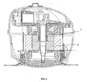
- FIGS 1 and 2 illustrate compressors comprising pumping solutions that are already in the prior art.
- the oil pump (1) is inserted in the rotor of the engine (2).
- the pump (1) has an end (3) plunged in the oil (4) disposed in a reservoir of the shell (5) and another end (6) inserted in the rotor (2).
- This configuration creates a free pathway for the oil, but restricts the region that is available for attaching the shaft (7) and the pump.
- the shaft (7) is continuous up to the superior end (6) of the pump.
- the pump (1) is inserted in the shaft (7), wherein said shaft (7) extends up to the end of the rotor (2).
- This configuration improves the region that is available for attaching the shaft (7), but the diameter of the oil passage is affected to enable the insertion of the pump in the shaft.
- the present invention discloses a pumping solution capable of guaranteeing a suitable diameter for passing the oil, an optimization of the upsetting height, and a simplified assembly means for the oil pump.
- the shaft (7) extends slightly from the rotor (2), leaving a free end (8) to enable the assembly of the centrifugal pump (1).
- the free end (8) has only a necessary extension for enabling the assembly of the pump (1). This is due to the need of non-extending too far the shaft (8), what would result in an unnecessary use of the material, elevating, therefore, the final cost of the compressor. Thus, in a preferred embodiment of the present invention, the extension of the free end is limited to 6 mm.
- one end of the pump (1) is plunged in the oil (4), wherein such end further comprises an input orifice (9) in its more extreme portion.
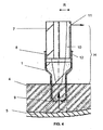
- the other end (12) of the pump (1) is sized to be connected with the free end (8) of the shaft (7), wherein the outer side wall of the shaft and the inner side wall of the pump are arranged in a juxtaposed condition after fitting.
- one part of the free end of the shaft (7) is machined to reduce its external diameter, wherein such machined part is reserved for receiving the end of the pump to be assembled.
- the assembly of the pump (1) on the free end (8) of the shaft (7) is carried out by interference fit, not being necessary the use of binders or adhesives.
- the assembly of the pump (1) on the free end (8) of the shaft (7) is carried out by means of binding.
- the centrifugal power causes the elevation of oil in the inner side wall of both pump and shaft in a parabolic configuration, as shown by number (10) in figure 4 .
- the pumping energy shall be sufficient so as the upsetting height reaches the output orifice where the first bearing is disposed, as shown by number (11) in such figure.
- the correct sizing of the parabolic column up to a height H depends on guaranteeing a sufficient radius R.
- the assembly of the pump (1) in an external position in relation to both shaft and rotor guarantees a suitable upsetting height, wherein the input orifice is naturally disposed closer to the shaft.
- the configuration for assembling the pump of the present invention achieves, by means of a simple and economic construction, a pumping solution that is efficient at providing a compressor operating at low rotation.
Landscapes
- Engineering & Computer Science (AREA)
- Mechanical Engineering (AREA)
- General Engineering & Computer Science (AREA)
- Compressor (AREA)
- Structures Of Non-Positive Displacement Pumps (AREA)
Abstract
The present invention refers to a hermetic compressor and, more specifically, a hermetic compressor comprising a centrifugal pump (1) to provide oil for the moving parts of said compressor. In the compressor of the present invention, the vertical shaft (7) extends axially from the rotor to form a free end (8) in its inferior portion, and said free end (8) is sized to be received in a corresponding end (12) of the centrifugal pump (1).
Description
- The present invention refers to a hermetic compressor and, more specifically, to a hermetic compressor comprising a centrifugal pump to provide oil for the moving parts of said compressor.
- A compressor has the function of elevating the pressure of a certain volume of fluid to a pressure that is required to carry out a determined work. The Refrigeration Industry commonly utilizes hermetic compressors comprising, in general, a sealed shell which defines, in its interior, an oil reservoir and an oil pump device that is responsible for leading the oil of the reservoir to the moving parts of the compressor.
- The Refrigeration Industry worries about the performance of the refrigeration compressors. In fact, several studies were carried out in order to improve such performance, wherein the latest generation of compressors utilizes variable speed drives. Upon varying the operational speed of the compressor, the capability of refrigerating can be set to the demand of the system, promoting a great benefit in energy consumption.
- A difficulty that results from the reduction of operational rotation is the pumping of the oil. Pumps normally used in those compressors are based on the centrifugal effect to lead the oil towards the parts to be lubricated. Those pumps are widely used due to its low cost and high reliability. Other alternatives with different principles can make the pumping in low rotation speeds possible, but the cost and the reliability are not competitive.
- The prior art oil pumps comprise an oil intake tube having an oil input. The intake stage depends on the centrifugal effect, wherein the pump rotation speed forces the oil that goes into the orifice against the walls of the tube, promoting the increase in pressure, and, consequently, its elevation.
- Thus, the pumping energy, that is necessary for lubricating, is obtained from the rotation and from the diameter of the pump. As a lower rotation is defined for the compressor to achieve a better performance of the same, which is applied to the refrigeration system, such rotation tends to be as low as possible, wherein the oil pump is the main limiting factor to decrease the rotation.
- Three main factors affect the efficiency of the pump: the diameter of the oil input orifice, the upsetting height (i.e. height between the suction point of the pump and the highest elevation point of the oil) and the radius or diameter of the pump.
- With reference to the first factor, the diameter of the input orifice of the pump creates a pressure equalization region, rendering such region inactive. The increase in pressure, which is resulted from the centrifugation, only occurs in regions having a higher diameter than the one of the input orifice. Thus, an input orifice having a very big diameter will prejudice the performance of the pump in low rotation speeds.
- Regarding the second factor, it shall be noted that the higher the upsetting height, the greater the energy necessary for pumping, since the oil shall be elevated up to the input orifice of the first bearing of the compressor. Subsequently, the propeller of the shaft will do the remaining pumping work.
- With respect to the third factor, it shall be noted that the radius or diameter of the pump in the oil output region (i.e., in the region of the input orifice of the first bearing of the compressor) is fundamental to the efficiency of the pump. This is due to the fact that the path followed by the oil through the shaft interior up to such output orifice shall consider the parabolic form acquired by the oil from its centrifugation, wherein no protuberance can intercept such parabola (if an interception occurs, the flux of oil will be simply interrupted).
- In view of the foregoing, the design of the pump has an important role in the performance of the compressor, further considering the need of a pump that is suitable for a compressor operating at a reduced rotation.
- Thus, one of the objectives of the invention is the provision of an efficient oil pump for being utilized with a hermetic compressor having a variable speed driver.
- Another objective of the present invention is the provision of an oil pump designed to efficiently actuate in a compressor operating at a reduced rotation.
- The present invention achieves the above-mentioned objectives by means of a hermetic compressor comprising a shell which involves the component parts of a compressor, an oil reservoir in the inferior part of the shell, a cylinder block that incorporates a bearing to support a vertical shaft on which a rotor is assembled, and a centrifugal pump that leads the oil to the moving parts of the compressor, wherein said vertical shaft extends axially from the rotor to form a free end in its inferior portion, the free end being sized to be received in a corresponding end of the centrifugal pump, and at least one portion of the inner sidewall of the end of the pump and at least one portion of the outer sidewall portion of the shaft assuming a juxtaposed condition after the reception.
- In order to avoid the unnecessary use of raw material, the free end of the vertical shaft extends axially, and only enough, to enable the attachment of the end of the pump, wherein, in a preferred embodiment, the free end of such vertical shaft extends up to a maximum of 6 mm.
- Furthermore, in said preferred embodiment of the present invention, the free end presents a machined portion having a reduced external diameter in order to facilitate the assembly of the end of the pump.
- The assembly between the free end of the shaft and the corresponding end of the pump is preferably effectuated by interference fit, but alternative means, such as binding, would be equally used.
- The figures show:
-
Figure 1 -Figure 1 illustrates a cut view of a conventional hermitic compressor comprising a pumping solution that is already known in the prior art; -
Figure 2 -Figure 2 illustrates a cut view of a conventional hermetic compressor comprising another pumping solution that is already known in the prior art; -
Figure 3 -Figure 3 illustrates a cut view of a hermetic compressor comprising the pumping solution provided by the present application; -
Figure 4 -Figure 4 illustrates a detailed cut view of the oil pump of the present invention, which is assembled on the compressor shaft. - The present invention will be described below, in a detailed manner, with basis on the examples of execution that are represented by the drawings. Although the detailed description utilizes, as an example, an alternative compressor for refrigeration, it shall be understood that the principles of the present invention can be applied to any type, size or configuration of hermetic compressor.
-
Figures 1 and2 illustrate compressors comprising pumping solutions that are already in the prior art. - In the solution illustrated in
figure 1 , the oil pump (1) is inserted in the rotor of the engine (2). The pump (1) has an end (3) plunged in the oil (4) disposed in a reservoir of the shell (5) and another end (6) inserted in the rotor (2). This configuration creates a free pathway for the oil, but restricts the region that is available for attaching the shaft (7) and the pump. In fact, as shown in such figure, the shaft (7) is continuous up to the superior end (6) of the pump. - In the solution illustrated in
figure 2 , the pump (1) is inserted in the shaft (7), wherein said shaft (7) extends up to the end of the rotor (2). This configuration improves the region that is available for attaching the shaft (7), but the diameter of the oil passage is affected to enable the insertion of the pump in the shaft. - The solution adopted by the present invention is illustrated in
figures 3 and4 . As can be noted upon reading the detailed description of such figures, the present invention discloses a pumping solution capable of guaranteeing a suitable diameter for passing the oil, an optimization of the upsetting height, and a simplified assembly means for the oil pump. - Thus, in the compressor of the present invention which is illustrated in
figure 3 , the shaft (7) extends slightly from the rotor (2), leaving a free end (8) to enable the assembly of the centrifugal pump (1). - It shall be emphasized that the free end (8) has only a necessary extension for enabling the assembly of the pump (1). This is due to the need of non-extending too far the shaft (8), what would result in an unnecessary use of the material, elevating, therefore, the final cost of the compressor. Thus, in a preferred embodiment of the present invention, the extension of the free end is limited to 6 mm.
- As better illustrated in
figure 4 , one end of the pump (1) is plunged in the oil (4), wherein such end further comprises an input orifice (9) in its more extreme portion. The other end (12) of the pump (1) is sized to be connected with the free end (8) of the shaft (7), wherein the outer side wall of the shaft and the inner side wall of the pump are arranged in a juxtaposed condition after fitting. - In the preferred embodiment of the present invention, one part of the free end of the shaft (7) is machined to reduce its external diameter, wherein such machined part is reserved for receiving the end of the pump to be assembled.
- Additionally, in the preferred embodiment of the present invention, the assembly of the pump (1) on the free end (8) of the shaft (7) is carried out by interference fit, not being necessary the use of binders or adhesives.
- However, it shall be noted that other forms of fitting and assembling could be utilized. Thus, in an alternative embodiment of the present invention, the assembly of the pump (1) on the free end (8) of the shaft (7) is carried out by means of binding.
- During the rotation of the pump (1), the centrifugal power causes the elevation of oil in the inner side wall of both pump and shaft in a parabolic configuration, as shown by number (10) in
figure 4 . The pumping energy shall be sufficient so as the upsetting height reaches the output orifice where the first bearing is disposed, as shown by number (11) in such figure. The correct sizing of the parabolic column up to a height H depends on guaranteeing a sufficient radius R. - In the present invention, the assembly of the pump (1) in an external position in relation to both shaft and rotor guarantees a suitable upsetting height, wherein the input orifice is naturally disposed closer to the shaft.
- In fact, as the assembly of the pump (1) does not take any internal extension of the shaft (7) in relation to the rotor, all interference region of the shaft is available, and the inferior end of the bearing (13) can be brought very close to the oil (see
figure 3 ), in such a way that the orifice (11) can be arranged in a upsetting height H that is easily reached even at low rotation. - Furthermore, as previously mentioned, once the pump (1) is externally assembled in relation to the shaft, it can be guaranteed a suitable radius R for enabling the parabolic pathway of the oil up to this reduced upsetting height.
- The configuration for assembling the pump of the present invention achieves, by means of a simple and economic construction, a pumping solution that is efficient at providing a compressor operating at low rotation.
- It shall be understood that the description provided with basis on the above-mentioned figures only refers to feasible embodiments for the hermetic cylinder of the present invention. The scope of the object of the present invention is defined in the appended claims.
Claims (6)
- A hermetic compressor comprising a shell (5) which involves the component parts of the compressor, an oil reservoir (4) in the inferior part of the shell, a block cylinder incorporating a bearing to support a vertical shaft (7) on which a rotor (2) is assembled, and a centrifugal pump (1) that leads the oil to the moving parts of the compressor, CHARACTERIZED in that said vertical shaft extends axially from the rotor (2) to form a free end (8) in its inferior portion, said free end being sized to be received in a corresponding end (12) of the centrifugal pump (1), and at least one portion of the inner sidewall of the end of the pump and at least one portion of the outer sidewall portion of the shaft assuming a juxtaposed condition after the reception.
- A hermetic compressor, in accordance with claim 1, CHARACTERIZED in that the free end (8) of the vertical shaft (7) extends axially, and only enough, to enable the attachment of the end of the pump.
- A hermetic compressor, in accordance with claim 2, CHARACTERIZED in that the free end (8) of the vertical shaft (7) extends up to a maximum of 6 mm.
- A hermetic compressor, in accordance with one of the preceding claims 1 to 3, CHARACTERIZED in that the free end (8) presents a machined portion having a reduced external diameter.
- A hermetic compressor, in accordance with one of the preceding claims 1 to 4, CHARACTERIZED in that the assembly between the free end (8) of the shaft and the corresponding end (12) of the pump (1) is carried out by interference fit.
- A hermetic compressor, in accordance with one of the preceding claims 1 to 4, CHARACTERIZED in that the assembly between the free end (8) of the shaft and the corresponding end (12) of the pump (1) is carried out by binding.
Applications Claiming Priority (2)
| Application Number | Priority Date | Filing Date | Title |
|---|---|---|---|
| BRPI0902430-1A BRPI0902430A2 (en) | 2009-07-24 | 2009-07-24 | airtight compressor |
| PCT/BR2010/000257 WO2011009186A1 (en) | 2009-07-24 | 2010-07-26 | Hermetic compressor |
Publications (1)
| Publication Number | Publication Date |
|---|---|
| EP2458213A1 true EP2458213A1 (en) | 2012-05-30 |
Family
ID=43063437
Family Applications (1)
| Application Number | Title | Priority Date | Filing Date |
|---|---|---|---|
| EP10752711A Withdrawn EP2458213A1 (en) | 2009-07-24 | 2010-07-26 | Hermetic compressor |
Country Status (10)
| Country | Link |
|---|---|
| US (1) | US20120189437A1 (en) |
| EP (1) | EP2458213A1 (en) |
| JP (1) | JP2013500415A (en) |
| KR (1) | KR20120034759A (en) |
| CN (1) | CN102483052A (en) |
| BR (1) | BRPI0902430A2 (en) |
| IN (1) | IN2012DN00706A (en) |
| MX (1) | MX2012001053A (en) |
| SG (1) | SG177748A1 (en) |
| WO (1) | WO2011009186A1 (en) |
Families Citing this family (2)
| Publication number | Priority date | Publication date | Assignee | Title |
|---|---|---|---|---|
| AT15828U1 (en) * | 2016-12-27 | 2018-07-15 | Secop Gmbh | LUBRICANT CONSUMPTION FOR A REFRIGERANT COMPRESSOR AND REFRIGERANT COMPRESSOR |
| AT15924U1 (en) * | 2017-04-28 | 2018-09-15 | Secop Gmbh | REFRIGERANT COMPRESSOR |
Family Cites Families (17)
| Publication number | Priority date | Publication date | Assignee | Title |
|---|---|---|---|---|
| US3285504A (en) * | 1964-12-10 | 1966-11-15 | Gen Motors Corp | Refrigerant apparatus |
| US4488855A (en) * | 1982-12-27 | 1984-12-18 | The Trane Company | Main bearing lubrication system for scroll machine |
| IT1159578B (en) * | 1983-05-03 | 1987-03-04 | Aspera Spa | CRANKSHAFT FOR HERMETIC REFRIGERATOR COMPRESSORS AND SIMILAR |
| US4518323A (en) * | 1983-07-25 | 1985-05-21 | Copeland Corporation | Hermetic refrigeration compressor |
| JPS60166784A (en) * | 1984-02-10 | 1985-08-30 | Mitsubishi Electric Corp | Scroll type compressor |
| JPS61155666A (en) * | 1984-12-27 | 1986-07-15 | Matsushita Refrig Co | Refrigerant compressor |
| KR870002381A (en) * | 1985-08-23 | 1987-03-31 | 미다 가쓰시게 | Shroul Compressor |
| JPH0647991B2 (en) * | 1986-05-15 | 1994-06-22 | 三菱電機株式会社 | Scroll compressor |
| JPH0735790B2 (en) * | 1986-06-23 | 1995-04-19 | 株式会社日立製作所 | Scroll compressor |
| US5219281A (en) * | 1986-08-22 | 1993-06-15 | Copeland Corporation | Fluid compressor with liquid separating baffle overlying the inlet port |
| GB2202905B (en) * | 1987-03-12 | 1991-07-24 | Matsushita Electric Industrial Co Ltd | Scroll compressor |
| JPS63223374A (en) * | 1987-03-12 | 1988-09-16 | Matsushita Electric Ind Co Ltd | electric compressor |
| JPH04140491A (en) * | 1990-09-28 | 1992-05-14 | Sanyo Electric Co Ltd | Closed type electric motor-driven compressor |
| CN1063831C (en) * | 1994-04-04 | 2001-03-28 | 巴西船用压缩机有限公司 | Oil pumps for variable speed hermetic compressors |
| DE10106234C2 (en) * | 2001-02-10 | 2002-12-12 | Danfoss Compressors Gmbh | piston compressor |
| JP2005140066A (en) * | 2003-11-10 | 2005-06-02 | Hitachi Ltd | Fluid compressor |
| EP1957796B1 (en) * | 2005-11-28 | 2010-06-30 | Arcelik Anonim Sirketi | A compressor |
-
2009
- 2009-07-24 BR BRPI0902430-1A patent/BRPI0902430A2/en not_active IP Right Cessation
-
2010
- 2010-07-26 JP JP2012520867A patent/JP2013500415A/en active Pending
- 2010-07-26 MX MX2012001053A patent/MX2012001053A/en not_active Application Discontinuation
- 2010-07-26 US US13/386,829 patent/US20120189437A1/en not_active Abandoned
- 2010-07-26 IN IN706DEN2012 patent/IN2012DN00706A/en unknown
- 2010-07-26 CN CN2010800375873A patent/CN102483052A/en active Pending
- 2010-07-26 EP EP10752711A patent/EP2458213A1/en not_active Withdrawn
- 2010-07-26 WO PCT/BR2010/000257 patent/WO2011009186A1/en not_active Ceased
- 2010-07-26 SG SG2012005237A patent/SG177748A1/en unknown
- 2010-07-26 KR KR1020127002084A patent/KR20120034759A/en not_active Withdrawn
Non-Patent Citations (1)
| Title |
|---|
| See references of WO2011009186A1 * |
Also Published As
| Publication number | Publication date |
|---|---|
| KR20120034759A (en) | 2012-04-12 |
| US20120189437A1 (en) | 2012-07-26 |
| IN2012DN00706A (en) | 2015-06-19 |
| MX2012001053A (en) | 2012-03-14 |
| SG177748A1 (en) | 2012-03-29 |
| WO2011009186A1 (en) | 2011-01-27 |
| CN102483052A (en) | 2012-05-30 |
| BRPI0902430A2 (en) | 2011-04-05 |
| JP2013500415A (en) | 2013-01-07 |
Similar Documents
| Publication | Publication Date | Title |
|---|---|---|
| CN1325796C (en) | Hermetic Electric Compressor | |
| US7748968B2 (en) | Two-cylinder rotary compressor with suction pipes | |
| CN202370792U (en) | Crankshaft applied to refrigeration compressor | |
| EP3214312A1 (en) | Two-cylinder hermetic compressor | |
| US8978826B2 (en) | Compressor | |
| CN203948296U (en) | Rotary compressor | |
| EP3214263A1 (en) | Two-cylinder hermetic compressor | |
| EP3409949A1 (en) | Rotary compressor having two cylinders | |
| EP2458213A1 (en) | Hermetic compressor | |
| CN110905771A (en) | Oil pumping system for crankshaft, compressor with oil pumping system and air conditioner | |
| EP2918773B1 (en) | Rotary compressor | |
| EP3922854A1 (en) | Rotary compressor, method for manufacturing rotary compressor, and refrigeration cycle device | |
| CN208816288U (en) | Crankshaft and frequency-changeable compressor | |
| KR101983458B1 (en) | Reciprocating compressor | |
| US20200158100A1 (en) | Refrigerant compressor | |
| WO2004104494A2 (en) | Discharge muffler having an internal pressure relief valve | |
| CN109185154B (en) | Pump body assembly and compressor | |
| KR101646044B1 (en) | Hermetic compressor and refrigerator using the same | |
| CN209494715U (en) | Compressor upper cylinder cover and compressor | |
| CN107387419A (en) | Oil-control component, pump and rotary compressor | |
| EP3211233B1 (en) | Two-cylinder hermetic compressor | |
| KR20110132940A (en) | Reciprocating compressors and freezers using them | |
| CN118257725A (en) | Crankshaft oil guide assembly and compressor | |
| CN105114324A (en) | Rolling rotary compressor | |
| KR19990036695A (en) | Fluid machinery |
Legal Events
| Date | Code | Title | Description |
|---|---|---|---|
| PUAI | Public reference made under article 153(3) epc to a published international application that has entered the european phase |
Free format text: ORIGINAL CODE: 0009012 |
|
| 17P | Request for examination filed |
Effective date: 20120124 |
|
| AK | Designated contracting states |
Kind code of ref document: A1 Designated state(s): AL AT BE BG CH CY CZ DE DK EE ES FI FR GB GR HR HU IE IS IT LI LT LU LV MC MK MT NL NO PL PT RO SE SI SK SM TR |
|
| DAX | Request for extension of the european patent (deleted) | ||
| 17Q | First examination report despatched |
Effective date: 20141211 |
|
| STAA | Information on the status of an ep patent application or granted ep patent |
Free format text: STATUS: THE APPLICATION IS DEEMED TO BE WITHDRAWN |
|
| 18D | Application deemed to be withdrawn |
Effective date: 20150422 |