EP2458212A2 - Swash plate compressor and surface treatment method for treating surface of swash plate in swash plate compressor - Google Patents
Swash plate compressor and surface treatment method for treating surface of swash plate in swash plate compressor Download PDFInfo
- Publication number
- EP2458212A2 EP2458212A2 EP11009216A EP11009216A EP2458212A2 EP 2458212 A2 EP2458212 A2 EP 2458212A2 EP 11009216 A EP11009216 A EP 11009216A EP 11009216 A EP11009216 A EP 11009216A EP 2458212 A2 EP2458212 A2 EP 2458212A2
- Authority
- EP
- European Patent Office
- Prior art keywords
- swash plate
- shoes
- executed
- sliding contact
- soft
- Prior art date
- Legal status (The legal status is an assumption and is not a legal conclusion. Google has not performed a legal analysis and makes no representation as to the accuracy of the status listed.)
- Withdrawn
Links
Images


Classifications
-
- F—MECHANICAL ENGINEERING; LIGHTING; HEATING; WEAPONS; BLASTING
- F04—POSITIVE - DISPLACEMENT MACHINES FOR LIQUIDS; PUMPS FOR LIQUIDS OR ELASTIC FLUIDS
- F04B—POSITIVE-DISPLACEMENT MACHINES FOR LIQUIDS; PUMPS
- F04B27/00—Multi-cylinder pumps specially adapted for elastic fluids and characterised by number or arrangement of cylinders
- F04B27/08—Multi-cylinder pumps specially adapted for elastic fluids and characterised by number or arrangement of cylinders having cylinders coaxial with, or parallel or inclined to, main shaft axis
- F04B27/0873—Component parts, e.g. sealings; Manufacturing or assembly thereof
- F04B27/0878—Pistons
- F04B27/0886—Piston shoes
-
- F—MECHANICAL ENGINEERING; LIGHTING; HEATING; WEAPONS; BLASTING
- F04—POSITIVE - DISPLACEMENT MACHINES FOR LIQUIDS; PUMPS FOR LIQUIDS OR ELASTIC FLUIDS
- F04B—POSITIVE-DISPLACEMENT MACHINES FOR LIQUIDS; PUMPS
- F04B27/00—Multi-cylinder pumps specially adapted for elastic fluids and characterised by number or arrangement of cylinders
- F04B27/08—Multi-cylinder pumps specially adapted for elastic fluids and characterised by number or arrangement of cylinders having cylinders coaxial with, or parallel or inclined to, main shaft axis
- F04B27/0804—Multi-cylinder pumps specially adapted for elastic fluids and characterised by number or arrangement of cylinders having cylinders coaxial with, or parallel or inclined to, main shaft axis having rotary cylinder block
- F04B27/0821—Multi-cylinder pumps specially adapted for elastic fluids and characterised by number or arrangement of cylinders having cylinders coaxial with, or parallel or inclined to, main shaft axis having rotary cylinder block component parts, details, e.g. valves, sealings, lubrication
- F04B27/086—Multi-cylinder pumps specially adapted for elastic fluids and characterised by number or arrangement of cylinders having cylinders coaxial with, or parallel or inclined to, main shaft axis having rotary cylinder block component parts, details, e.g. valves, sealings, lubrication swash plate
-
- F—MECHANICAL ENGINEERING; LIGHTING; HEATING; WEAPONS; BLASTING
- F04—POSITIVE - DISPLACEMENT MACHINES FOR LIQUIDS; PUMPS FOR LIQUIDS OR ELASTIC FLUIDS
- F04B—POSITIVE-DISPLACEMENT MACHINES FOR LIQUIDS; PUMPS
- F04B27/00—Multi-cylinder pumps specially adapted for elastic fluids and characterised by number or arrangement of cylinders
- F04B27/08—Multi-cylinder pumps specially adapted for elastic fluids and characterised by number or arrangement of cylinders having cylinders coaxial with, or parallel or inclined to, main shaft axis
- F04B27/10—Multi-cylinder pumps specially adapted for elastic fluids and characterised by number or arrangement of cylinders having cylinders coaxial with, or parallel or inclined to, main shaft axis having stationary cylinders
- F04B27/1036—Component parts, details, e.g. sealings, lubrication
- F04B27/1054—Actuating elements
-
- F—MECHANICAL ENGINEERING; LIGHTING; HEATING; WEAPONS; BLASTING
- F05—INDEXING SCHEMES RELATING TO ENGINES OR PUMPS IN VARIOUS SUBCLASSES OF CLASSES F01-F04
- F05C—INDEXING SCHEME RELATING TO MATERIALS, MATERIAL PROPERTIES OR MATERIAL CHARACTERISTICS FOR MACHINES, ENGINES OR PUMPS OTHER THAN NON-POSITIVE-DISPLACEMENT MACHINES OR ENGINES
- F05C2203/00—Non-metallic inorganic materials
- F05C2203/08—Ceramics; Oxides
- F05C2203/0804—Non-oxide ceramics
- F05C2203/083—Nitrides
-
- F—MECHANICAL ENGINEERING; LIGHTING; HEATING; WEAPONS; BLASTING
- F05—INDEXING SCHEMES RELATING TO ENGINES OR PUMPS IN VARIOUS SUBCLASSES OF CLASSES F01-F04
- F05C—INDEXING SCHEME RELATING TO MATERIALS, MATERIAL PROPERTIES OR MATERIAL CHARACTERISTICS FOR MACHINES, ENGINES OR PUMPS OTHER THAN NON-POSITIVE-DISPLACEMENT MACHINES OR ENGINES
- F05C2253/00—Other material characteristics; Treatment of material
- F05C2253/12—Coating
-
- F—MECHANICAL ENGINEERING; LIGHTING; HEATING; WEAPONS; BLASTING
- F05—INDEXING SCHEMES RELATING TO ENGINES OR PUMPS IN VARIOUS SUBCLASSES OF CLASSES F01-F04
- F05C—INDEXING SCHEME RELATING TO MATERIALS, MATERIAL PROPERTIES OR MATERIAL CHARACTERISTICS FOR MACHINES, ENGINES OR PUMPS OTHER THAN NON-POSITIVE-DISPLACEMENT MACHINES OR ENGINES
- F05C2253/00—Other material characteristics; Treatment of material
- F05C2253/24—Heat treatment
Definitions
- the present invention relates to a swash plate compressor that includes shoes which slide in contact against each piston caused to move reciprocally as a swash plate rotates, and against the swash plate, assuring better wear and abrasion resistance and better slideability for the swash plate and the shoes.
- the present invention also relates to a surface treatment method that may be adopted when treating a surface of the swash plate of such a swash plate compressor.
- a swash plate compressor utilized in a wide range of applications as a coolant compressor in an automotive air-conditioner and the like, typically comprises : (a) a shaft passing through a crank chamber and rotatably supported at a housing, (b) a swash plate that includes an opening through which the shaft is inserted, is disposed in the crank chamber and rotates synchronously with rotation of the shaft, (c) pistons, each held at a circumferential edge of the swash plate and caused to slide reciprocally through a cylinder bore formed at the housing as the swash plate rotates and (d) shoes, each disposed between one of two side surfaces of the swash plate and an engaging portion of the piston to slide in contact against both the swash plate and the piston.
- Such a swash plate compressor with the swash plate thereof caused to rotate at high speed under a considerable load, needs to assure good slideability for the swash plate and the shoes.
- requirements pertaining to various characteristics including a high level of lubricity so as to allow the swash plate and the shoes to slide in contact against each other smoothly, outstanding wear and abrasion resistance so as to ensure that the swash plate and the shoes do not wear out easily and superior anti-seizure characteristics so that the swash plate and the shoes do not seize up.
- the sliding contact surfaces of the swash plate and the shoes may be hardened or a coating constituted of a solid lubricant may be formed at the sliding contact surface of either the swash plate or the shoe.
- the quenching temperature is bound to be high and thus, there is a concern that the swash plate may become warped.
- variable-capacity swash plate compressor known in the related art, comprising a rotating member fixed to a rotating shaft, which rotates as one with the rotating shaft, a swash plate tiltably supported at the rotating shaft and linked to the rotating member via a link mechanism. This latest rotates as one with the rotating member as the rotating member rotates and pistons each linked with the swash plate via shoes engaged in a relative rotation over sliding contact surfaces of the swash plate.
- the swash plate reciprocates linearly in a cylinder bore as the swash plate rotates, with a projecting portion that constitutes part of the link mechanism, disposed at the swash plate.
- the Japanese Laid Open Patent Publication No. H 10-196531 describes such a variable-capacity swash plate compressor wherein the swash plate and the projecting portion have undergone a surface treatment process executed by adopting either a gas nitro-sulfurizing treatment method or an electroless nickel-phosphor-boron plating treatment method.
- a swash plate compressor comprising a rotating shaft, a swash plate supported with a tilt by the rotating shaft, a housing that rotatably supports the rotating shaft while disallowing displacement of the rotating shaft along the axial direction and includes cylinder bores formed at a position decentered from and substantially parallel to the rotating shaft, pistons that each includes a head portion slidably fitted in the cylinder bore and an engaging portion astride a circumferential edge portion of the swash plate and is caused to move reciprocally as the swash plate rotates and shoes, each disposed between one of the two side surfaces of the swash plate and the engaging portion of the piston to slide in contact with both the swash plate and the piston.
- the swash plate is constituted of an iron-based material with a lubricant coating formed at least at sliding contact surfaces thereof that slide in contact against the shoes and that the shoes are nitrified shoes with at least part thereof constituted of an iron-based material and at least sliding contact surface thereof located toward the swash plate, which slides in contact against the swash plate, having undergone a soft nitriding process.
- a nitride-containing compound layer is formed at the sliding contact surfaces of the swash plate, raising the hardness of the swash plate sliding contact surface relative to that of the sliding contact surface of each shoe. This gives rise to a concern that as the shoes slide in contact against the swash plate, it may become damaged.
- the sliding contact surfaces of the swash plate the hardness of which has risen through the nitriding process, is finished with a lathe, the service life of the tool bit may be shortened.
- the lubricant coating formed at the sliding contact surfaces of the swash plate in the variable-capacity swash plate compressor disclosed in the Japanese Laid Open Patent Publication No. 2003-42061 is bound to be ground off, resulting in the formation of a dent.
- both the swash plate and the shoes will be damaged and eventually, they may no longer be able to slide in contact against each other smoothly.
- the swash plate compressor is assembled with each shoe mounted with its surface assuming a mirror surface state with hardly any roughness
- the swash plate is mounted with its surface in a coarser state compared to the shoe surfaces. If the hardness of the swash plate is higher than each shoe with the swash plate and the shoes assuming different surface conditions, as described above, the swash plate is bound to damage the surface of the shoes and as they continue to slide in contact against each other, the scarred surface of each shoe will then scar the swash plate and the lubricant coating will flake off, which will ultimately result in poorer slideability and hastening of wear at the swash plate and the shoes.
- a primary object of the present invention having been achieved by addressing the issues discussed above, is to provide a swash plate compressor assuring better wear and abrasion resistance and better slideability for the swash plate and the shoes and also to provide a surface treatment method that may be adopted when treating the surface of the swash plate of such a swash plate compressor.
- the swash plate compressor comprises a shaft passing through a crank chamber and rotatably supported at a housing, a swash plate that includes an opening through which the shaft is inserted, is disposed in the crank chamber and rotates synchronously with rotation of the shaft, pistons, each held at a circumferential edge of the swash plate, which slides reciprocally in a cylinder bore formed at the housing as the swash plate rotates, and shoes, each disposed between one of the two side surfaces of the swash plate and an engaging portion of the piston to slide in contact against both the swash plate and the piston, characterized in that the swash plate is constituted of an iron-based material and that sliding contact surfaces of the swash plate that slide in contact against said shoes undergoes a finish machining process, a gas soft-nitriding process executed as a hardening treatment process following the finish machining process, a removal process executed after the soft-nitriding process in order to remove a nitride-containing compound layer while
- the swash plate compressor is further characterized in that the shoes will have undergone a heat hardening treatment process and that the hardness of the swash plate will have been lowered relative to the hardness of each shoe through the removal process.
- the wear and abrasion resistance of both the shoes and the swash plate can be improved while ensuring that the shoes are reliably protected.
- the solid lubricant is caused penetrate into minute recesses and projections formed at the sliding contact surfaces of the swash plate through the shot blast process, so as to further increase the adhesive strength of the lubricant coating through an anchoring effect.
- the solid lubricant be a fluororesin.
- the hardened layer formed at the sliding contact surfaces of the swash plate assumes a high level of affinity with a fluororesin and thus, a better lubricating effect and a higher level of hardness will be achieved at the same time.
- a condition in which the hardened layer, having been formed through the soft-nitriding process, is mixed in the lubricating layer in a microscopic view will be assumed, thereby achieving both the lubricating effect and the anti-wear effect, which ultimately makes it possible to prevent the swash plate and the shoes from seizing.
- the swash plate By executing the finish machining process step prior to the soft-nitriding process step, the swash plate can be machined in a state in which its hardness is low and thus the machinability of the swash plate is improved. Furthermore, by executing the finish machining process prior to the soft-nitriding process, the need to execute a nitride-preventing process is eliminated, making it possible to lower the manufacturing cost.
- a removal process is executed to remove the nitride-containing compound while retaining the hardened layer, having been formed through the soft-nitriding process and then, following the removal process, a coating process is executed to form a solid lubricant coating.
- the anchoring effect achieved through the shotblast process prevents the self-lubricating material from peeling off.
- FIG. 1 is a diagram showing the structure adopted in a swash plate compressor.
- FIG. 2 is an enlarged view of a sliding contact surface of the swash plate that slides in contact against shoes.
- FIG. 3 is a graph of the hardness of the swash plate in the swash type compressor.
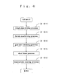
- FIG. 4 presents a flowchart of manufacturing processes through which the swash plate in the swash plate compressor is manufactured.
- a variable capacity swash plate compressor 1 includes a cylinder block 2, a rear head 4 mounted on the rear side (on the right side in the figure) of the cylinder block 2 via a valve plate 3, and a front head 5 mounted so as to close off the front side (the left side in the figure) of the cylinder block 2.
- a shaft 9, one end of which projects out from the front head 5, is housed.
- a relay member 11 mounted along the axial direction with a bolt 10 is fixed to the portion of the shaft 9 projecting out of the front head 5, and a drive pulley 12, which is rotatably fitted over an end of the front head 5 and linked to the vehicle engine via a belt, is fastened to the relay member 11 via locking means such as screws.
- the one end of the shaft 9 is sealed via a seal member 13 disposed between the one end of the shaft 9 and the front head 5 so as to assure a high level of airtightness between the one end and the front head 5.
- the one end of the shaft 9 is also rotatably supported by a radial bearing 14, whereas the other end of the shaft 9 is rotatably supported by a radial bearing 15 housed inside the cylinder block 2.
- a through hole 16, where the radial bearing 15 is housed, and a plurality of cylinder bores 17, set over equal intervals on the circumference of a circle centered on the through hole 16, are formed.
- Each piston 18 is inserted in each cylinder bore 17 so as to be allowed to reciprocally slide in the cylinder bore 17.
- the piston 18, formed as a hollow member, includes a head portion 18a to be inserted into the cylinder bore 17 connected along the axial direction to an engaging portion 18b to project out into the crank chamber.
- a thrust flange 19, which is to rotate as one with the shaft 9 is fixed to the shaft 9 within the crank chamber 8.
- This thrust flange 19 is rotatably supported at the front head 5 via a thrust bearing 20 so as to be allowed to rotate freely relative to the front head 5 and the swash plate 22 is linked to the thrust flange 19 via a link member 21.
- the circumferential edge portion of the swash plate 22 is held at the engaging portion 18b of each piston 18 via a pair of shoes 24 disposed at the front and rear sides of the swash plate 22.
- a suction hole 25 and a discharge hole 26 are formed in correspondence to each cylinder bore 17, whereas a suction chamber 27 where a working fluid to be supplied into the compression spaces is stored and a discharge chamber 28 where the working fluid discharged from the compression spaces is stored are defined at the rear head 4.
- the suction chamber 27, formed in a central area of the rear head 4, is in communication with a suction port 29 communicating with the outlet side of an evaporator and is also allowed to communicate with the compression spaces via the suction holes 25 formed at the valve plate 3.
- the discharge chamber 28, formed continuously around the suction chamber 27, is in communication with a discharge port communicating with the intake side of the condenser (not shown) and is also allowed to communicate with the compression spaces via the discharge holes 26 formed at the valve plate 3.
- the suction holes 25 are each opened or closed with a suction valve 30 disposed at an end surface of the valve plate 3 located on the front side, whereas the discharge holes 26 are each opened or closed with a discharge valve 31 disposed at an end surface of the valve plate 3 located on the rear side.
- the shoes 24 are each formed in a spherical crown shape and include a piston-side sliding contact surface 32, which achieves a convex spherical contour and slides in contact against a piston 18, and a swash plate side sliding contact surface 33, which is a flat surface and slides in contact against the swash plate 22.
- the pair of shoes 24, are each slidably held at the piston-side sliding contact surface 32 thereof so as to slide in contact against the concave spherical surfaces of a piston 18.
- the swash plate side sliding contact surfaces 33 of the shoes 24 slide in contact with the swash plate 22 at sliding contact surfaces 34 , 35 located on the both sides of the outer portion of the swash plate 22. That is, the outer portion of the swash plate is sandwiched between the pair of shoes 24.
- the shoe 24 is manufactured by forging a raw part from a blank made of bearing steel such as SUJ2, hardening (quenching) the raw part in a hardening treatment process and then polishing the sliding contact surfaces. Through the hardening process, their hardness is raised to approximately 850 Hv.
- a hardened layer 36 is formed at both the sliding contact surfaces 34, 35 that slide in contact against the shoes 24.
- a lubricant coating 37 constituted of a self-lubricating material is formed over the surface of the hardened layer 36. It is to be noted that FIG. 2 shows the hardened layer 36 and the lubricant coating 37 with their thicknesses exaggerated so as to provide a clear illustration.
- the hardened layer 36 is constituted with a diffusion layer formed by removing the nitride-containing compound layer having been formed at the outermost surface through a gas soft-nitriding process. More specifically, it is constituted with a layer formed with nitrogen atoms having entered and dissolved between atoms forming a ferrite metal crystal lattice in the forged iron material used to constitute the swash plate or a layer formed by depositing a dispersed nitride of an added element onto a parent phase with nitrogen dissolved therein.
- the sliding contact surfaces 34 and 35 undergo the gas soft-nitriding process executed by diffusing a nitrogen gas through an ammonia gas atmosphere at approximately 500 to 600°C so as to form a nitride-containing compound layer (with a thickness of approximately 0.01 mm) over their outermost surfaces and to form a hardened layer 36 underneath the nitride-containing compound layer.
- the hardness of the nitride-containing compound layer at approximately 1000 Hv is higher than the hardness of the swash plate side sliding contact surface 33 of each shoe 24 and thus, as the shoe 24 slides in contact against the swash plate 22 at high speed, the swash plate side sliding contact surface 33 of the shoe 24 may become scarred.
- the sliding contact surfaces 34 and 35 are formed so as to expose the hardened layer 36 with a hardness of approximately 600 Hv located directly underneath the compound layer by removing only the nitride-containing compound layer. Consequently, a sufficient level of hardness (550 Hv or higher), required to assure satisfactory wear and abrasion tolerance, is achieved while keeping the hardness lower than that of the swash plate side sliding contact surface 33 of each shoe 24.
- a fluororesin may be, for instance, polytetrafluoroethylene (tetra fluororesin: PTFE), polychloro trifluoroethylene (trifluororesin: PCTFE, CTFE), polyvinylidene fluoride (PVDF), polyvinyl fluoride (PVF), perfluoroalchoxy fluororesin (PFA), tetrafluoroethylene ⁇ hexafluoride propylene copolymer (FEP), ethylene - tetrafluoroethylene copolymer (ETFE), ethylene-chlorotrifluoroethylene copolymer (ECTFE) or the like.
- the swash plate 22 is formed by machining an iron-based cast material such as FCD 600. In more specific terms, it is manufactured through the steps shown in FIG. 4 .
- a rough machining process by using a lathe is executed (S101) so as to form the rough part of the swash plate 22 having been molded through casting into a shape closer to the ultimate shape.
- the sliding contact surfaces 34 and 35 to slide in contact against the shoes 24 undergo a finish machining process (S102) by using a lathe so as to further improve the dimensional accuracy.
- a gas soft-nitriding process is executed (S103) so as to harden the sliding contact surfaces, and then a shotblast process is executed (S104) in order to remove the nitride-containing compound having been formed through the gas soft-nitriding process.
- a fluororesin coating process is executed (S105) so as to form a lubricant coating 37 at the sliding contact surfaces 34 and 35.
- the high level of affinity between the hardened layer 36 and the lubricant coating 37 allows the fluororesin, having entered the recesses as described above, to be mixed into the hardened layer 36 at a microscopic level, making it possible to achieve improvement in both lubrication and hardness.
- step S102 by executing the finish machining process in step S102 prior to the soft-nitriding process executed in step S103, any damage that may be induced at the tool bit of the lathe is minimized, so as to lengthen the cycles over which the tool bit needs to be replaced.
Landscapes
- Engineering & Computer Science (AREA)
- Mechanical Engineering (AREA)
- General Engineering & Computer Science (AREA)
- Manufacturing & Machinery (AREA)
- Compressors, Vaccum Pumps And Other Relevant Systems (AREA)
- Solid-Phase Diffusion Into Metallic Material Surfaces (AREA)
Abstract
Description
- The present invention relates to a swash plate compressor that includes shoes which slide in contact against each piston caused to move reciprocally as a swash plate rotates, and against the swash plate, assuring better wear and abrasion resistance and better slideability for the swash plate and the shoes. The present invention also relates to a surface treatment method that may be adopted when treating a surface of the swash plate of such a swash plate compressor.
- A swash plate compressor, utilized in a wide range of applications as a coolant compressor in an automotive air-conditioner and the like, typically comprises : (a) a shaft passing through a crank chamber and rotatably supported at a housing, (b) a swash plate that includes an opening through which the shaft is inserted, is disposed in the crank chamber and rotates synchronously with rotation of the shaft, (c) pistons, each held at a circumferential edge of the swash plate and caused to slide reciprocally through a cylinder bore formed at the housing as the swash plate rotates and (d) shoes, each disposed between one of two side surfaces of the swash plate and an engaging portion of the piston to slide in contact against both the swash plate and the piston.
- Such a swash plate compressor, with the swash plate thereof caused to rotate at high speed under a considerable load, needs to assure good slideability for the swash plate and the shoes. In other words, it is necessary that requirements pertaining to various characteristics be fulfilled, including a high level of lubricity so as to allow the swash plate and the shoes to slide in contact against each other smoothly, outstanding wear and abrasion resistance so as to ensure that the swash plate and the shoes do not wear out easily and superior anti-seizure characteristics so that the swash plate and the shoes do not seize up. As a means for fulfilling these requirements, the sliding contact surfaces of the swash plate and the shoes may be hardened or a coating constituted of a solid lubricant may be formed at the sliding contact surface of either the swash plate or the shoe.
- While the swash plate may be hardened through a quenching process, the quenching temperature is bound to be high and thus, there is a concern that the swash plate may become warped.
- As a viable alternative to the quenching process, a soft-nitriding process through which the sliding contact surfaces can be hardened at a temperature lower than the quenching temperature is executed. More specifically, there is a variable-capacity swash plate compressor known in the related art, comprising a rotating member fixed to a rotating shaft, which rotates as one with the rotating shaft, a swash plate tiltably supported at the rotating shaft and linked to the rotating member via a link mechanism. This latest rotates as one with the rotating member as the rotating member rotates and pistons each linked with the swash plate via shoes engaged in a relative rotation over sliding contact surfaces of the swash plate. The swash plate reciprocates linearly in a cylinder bore as the swash plate rotates, with a projecting portion that constitutes part of the link mechanism, disposed at the swash plate.
- The Japanese Laid Open Patent Publication No.
H 10-196531 - The Japanese Laid Open Patent Publication No.
2003-42061 - As the nitriding process is executed while manufacturing the variable capacity swash plate compressor disclosed in the Japanese Laid Open Patent Publication No.
H10-196531 - As the swash plate and the shoes slide in contact against each other, the lubricant coating formed at the sliding contact surfaces of the swash plate in the variable-capacity swash plate compressor disclosed in the Japanese Laid Open Patent Publication No.
2003-42061 - In more specific terms, while the swash plate compressor is assembled with each shoe mounted with its surface assuming a mirror surface state with hardly any roughness, the swash plate is mounted with its surface in a coarser state compared to the shoe surfaces. If the hardness of the swash plate is higher than each shoe with the swash plate and the shoes assuming different surface conditions, as described above, the swash plate is bound to damage the surface of the shoes and as they continue to slide in contact against each other, the scarred surface of each shoe will then scar the swash plate and the lubricant coating will flake off, which will ultimately result in poorer slideability and hastening of wear at the swash plate and the shoes.
- A primary object of the present invention having been achieved by addressing the issues discussed above, is to provide a swash plate compressor assuring better wear and abrasion resistance and better slideability for the swash plate and the shoes and also to provide a surface treatment method that may be adopted when treating the surface of the swash plate of such a swash plate compressor.
- The swash plate compressor according to the present invention comprises a shaft passing through a crank chamber and rotatably supported at a housing, a swash plate that includes an opening through which the shaft is inserted, is disposed in the crank chamber and rotates synchronously with rotation of the shaft, pistons, each held at a circumferential edge of the swash plate, which slides reciprocally in a cylinder bore formed at the housing as the swash plate rotates, and shoes, each disposed between one of the two side surfaces of the swash plate and an engaging portion of the piston to slide in contact against both the swash plate and the piston, characterized in that the swash plate is constituted of an iron-based material and that sliding contact surfaces of the swash plate that slide in contact against said shoes undergoes a finish machining process, a gas soft-nitriding process executed as a hardening treatment process following the finish machining process, a removal process executed after the soft-nitriding process in order to remove a nitride-containing compound layer while retaining a hardened layer having been formed through the soft-nitriding process, and a coating process executed after the removal process to form a coating constituted of a solid lubricant on the sliding contact surfaces.
- Through the removal process executed to remove the nitride-containing compound layer with the hardness thereof higher than that of the each shoe while retaining the hardened layer having been formed through the nitriding process, it is ensured that the shoes do not become damaged. At the same time, with the retained hardened layer, a sufficient level of hardness is assured to achieve a satisfactory degree of wear and abrasion resistance. In addition, the presence of the solid lubricant coating formed at the sliding contact surfaces assure better slideability for the swash plate and the shoes.
- The swash plate compressor is further characterized in that the shoes will have undergone a heat hardening treatment process and that the hardness of the swash plate will have been lowered relative to the hardness of each shoe through the removal process.
- With the hardness of the each shoe raised through the heat hardening treatment process and the hardness of the swash plate lowered relative to that of each shoe through the removal process, the wear and abrasion resistance of both the shoes and the swash plate can be improved while ensuring that the shoes are reliably protected.
- It is desirable that a shot blast process be executed as the removal process.
- The solid lubricant is caused penetrate into minute recesses and projections formed at the sliding contact surfaces of the swash plate through the shot blast process, so as to further increase the adhesive strength of the lubricant coating through an anchoring effect.
- Furthermore, it is desirable that the solid lubricant be a fluororesin.
- The hardened layer formed at the sliding contact surfaces of the swash plate assumes a high level of affinity with a fluororesin and thus, a better lubricating effect and a higher level of hardness will be achieved at the same time. In other words, even if the layer constituted of solid lubricant partially peels off, a condition in which the hardened layer, having been formed through the soft-nitriding process, is mixed in the lubricating layer in a microscopic view will be assumed, thereby achieving both the lubricating effect and the anti-wear effect, which ultimately makes it possible to prevent the swash plate and the shoes from seizing.
- In addition, it is desirable that the surface treatment method to be adopted when treating a surface of a swash plate in a swash plate compressor comprising a shaft passing through a crank chamber and rotatably supported at a housing, the swash plate that includes an opening through which the shaft is inserted, is disposed in the crank chamber and rotates synchronously with rotation of the shaft, pistons, each held at a circumferential edge of the swash plate, which slides reciprocally in a cylinder bore formed at the housing as the swash plate rotates, and shoes, each disposed between one of the two side surfaces of the swash plate and an engaging portion of the piston to slide in contact against both the swash plate and the piston, with the swash plate constituted of an iron-based material comprise a step in which a finish machining process is executed to finish sliding contact surfaces of the swash plate to slide in contact against said shoes, a step in which a soft-nitriding process is executed on the sliding contact surfaces having undergone the finish machining process, a step in which a removal process is executed on the sliding contact surfaces having undergone the soft-nitriding process so as to remove a nitride-containing compound while retaining a hardened layer, having been formed through the soft-nitriding process, and a step in which a coating process is executed on the sliding contact surfaces having undergone the removal process so as to form a coating constituted of a solid lubricant.
- By executing the finish machining process step prior to the soft-nitriding process step, the swash plate can be machined in a state in which its hardness is low and thus the machinability of the swash plate is improved. Furthermore, by executing the finish machining process prior to the soft-nitriding process, the need to execute a nitride-preventing process is eliminated, making it possible to lower the manufacturing cost.
- It is desirable that a shotblast process be executed as the removal process.
- According to the present invention described above, after the sliding contact surfaces of the swash plate that slides in contact with the shoes undergoes the soft-nitriding process, a removal process is executed to remove the nitride-containing compound while retaining the hardened layer, having been formed through the soft-nitriding process and then, following the removal process, a coating process is executed to form a solid lubricant coating. As a result, better wear and abrasion resistance and better slideability are assured for the swash plate and the shoes, making it possible to effectively prevent seizure.
- In addition, by raising the hardness of each shoe through a heat hardening treatment process and also adjusting the hardness of the swash plate to a level lower than that of each shoe, the wear and abrasion resistance of both the shoes and the swash plate can be improved since the shoes are not subjected to any risk of damage.
- Furthermore, the anchoring effect achieved through the shotblast process prevents the self-lubricating material from peeling off.
- Moreover, by using a self-lubricating material constituted of a fluororesin, which demonstrates a high level of affinity with the hardened layer constituted of the nitride-containing compound, better lubrication and greater hardness can be achieved.
- In addition, through the soft-nitriding process executed after the finish machining process, an improvement in the machinability is achieved, which, in turn, lengthens the cycles over which wear-out tools must be replaced, thus making it possible to keep down the production costs. Furthermore, since the need to execute an additional process such as nitride-preventing process is eliminated, the manufacturing cost can be further reduced.
-
FIG. 1 is a diagram showing the structure adopted in a swash plate compressor. -
FIG. 2 is an enlarged view of a sliding contact surface of the swash plate that slides in contact against shoes. -
FIG. 3 is a graph of the hardness of the swash plate in the swash type compressor. -
FIG. 4 presents a flowchart of manufacturing processes through which the swash plate in the swash plate compressor is manufactured. - The following is a description of the swash plate compressor according to the present invention, given in reference to the drawings.
- As shown in
FIG. 1 , a variable capacity swash plate compressor 1 according to the present invention includes acylinder block 2, a rear head 4 mounted on the rear side (on the right side in the figure) of thecylinder block 2 via a valve plate 3, and afront head 5 mounted so as to close off the front side (the left side in the figure) of thecylinder block 2. Thefront head 5, thecylinder block 2, the valve plate 3 and the rear head 4, fastened together along the axial direction with fasteningbolts 6, together constitute a housing 7 that houses the entire compressor. - In a crank chamber 8 defined by the
front head 5 and thecylinder block 2, ashaft 9, one end of which projects out from thefront head 5, is housed. Arelay member 11 mounted along the axial direction with abolt 10 is fixed to the portion of theshaft 9 projecting out of thefront head 5, and adrive pulley 12, which is rotatably fitted over an end of thefront head 5 and linked to the vehicle engine via a belt, is fastened to therelay member 11 via locking means such as screws. The one end of theshaft 9 is sealed via aseal member 13 disposed between the one end of theshaft 9 and thefront head 5 so as to assure a high level of airtightness between the one end and thefront head 5. The one end of theshaft 9 is also rotatably supported by aradial bearing 14, whereas the other end of theshaft 9 is rotatably supported by a radial bearing 15 housed inside thecylinder block 2. - At the
cylinder block 2, a throughhole 16, where theradial bearing 15 is housed, and a plurality ofcylinder bores 17, set over equal intervals on the circumference of a circle centered on the throughhole 16, are formed. Eachpiston 18 is inserted in eachcylinder bore 17 so as to be allowed to reciprocally slide in thecylinder bore 17. Thepiston 18, formed as a hollow member, includes ahead portion 18a to be inserted into thecylinder bore 17 connected along the axial direction to anengaging portion 18b to project out into the crank chamber. - A
thrust flange 19, which is to rotate as one with theshaft 9 is fixed to theshaft 9 within the crank chamber 8. Thisthrust flange 19 is rotatably supported at thefront head 5 via a thrust bearing 20 so as to be allowed to rotate freely relative to thefront head 5 and theswash plate 22 is linked to thethrust flange 19 via alink member 21. Theswash plate 22, mounted tiltably to allow a tilting motion centered on ahinge ball 23 disposed on theshaft 9, rotates as one with thethrust flange 19 by syncing with the rotation of thethrust flange 19. The circumferential edge portion of theswash plate 22 is held at the engagingportion 18b of eachpiston 18 via a pair ofshoes 24 disposed at the front and rear sides of theswash plate 22. - Thus, as the
shaft 9 rotates, theswash plate 22 also rotates, the rotating motion of theswash plate 32 is converted to linear reciprocal motion of thepistons 18 via theshoes 24 and, as a result, the volumetric capacity of a compression space formed between thepiston 18 and the valve plate 3 inside each cylinder bore changes. - At the valve plate 3, a
suction hole 25 and adischarge hole 26 are formed in correspondence to each cylinder bore 17, whereas asuction chamber 27 where a working fluid to be supplied into the compression spaces is stored and adischarge chamber 28 where the working fluid discharged from the compression spaces is stored are defined at the rear head 4. Thesuction chamber 27, formed in a central area of the rear head 4, is in communication with asuction port 29 communicating with the outlet side of an evaporator and is also allowed to communicate with the compression spaces via the suction holes 25 formed at the valve plate 3. In addition, thedischarge chamber 28, formed continuously around thesuction chamber 27, is in communication with a discharge port communicating with the intake side of the condenser (not shown) and is also allowed to communicate with the compression spaces via the discharge holes 26 formed at the valve plate 3. The suction holes 25 are each opened or closed with asuction valve 30 disposed at an end surface of the valve plate 3 located on the front side, whereas the discharge holes 26 are each opened or closed with a discharge valve 31 disposed at an end surface of the valve plate 3 located on the rear side. - As shown in
FIG. 1 andFIG.2 , theshoes 24 are each formed in a spherical crown shape and include a piston-side slidingcontact surface 32, which achieves a convex spherical contour and slides in contact against apiston 18, and a swash plate side slidingcontact surface 33, which is a flat surface and slides in contact against theswash plate 22. The pair ofshoes 24, are each slidably held at the piston-side slidingcontact surface 32 thereof so as to slide in contact against the concave spherical surfaces of apiston 18. The swash plate side sliding contact surfaces 33 of theshoes 24 slide in contact with theswash plate 22 at sliding contact surfaces 34 , 35 located on the both sides of the outer portion of theswash plate 22. That is, the outer portion of the swash plate is sandwiched between the pair ofshoes 24. - The
shoe 24 is manufactured by forging a raw part from a blank made of bearing steel such as SUJ2, hardening (quenching) the raw part in a hardening treatment process and then polishing the sliding contact surfaces. Through the hardening process, their hardness is raised to approximately 850 Hv. - At the
swash plate 22, ahardened layer 36 is formed at both the sliding contact surfaces 34, 35 that slide in contact against theshoes 24. Alubricant coating 37 constituted of a self-lubricating material is formed over the surface of thehardened layer 36. It is to be noted thatFIG. 2 shows thehardened layer 36 and thelubricant coating 37 with their thicknesses exaggerated so as to provide a clear illustration. - The
hardened layer 36 is constituted with a diffusion layer formed by removing the nitride-containing compound layer having been formed at the outermost surface through a gas soft-nitriding process. More specifically, it is constituted with a layer formed with nitrogen atoms having entered and dissolved between atoms forming a ferrite metal crystal lattice in the forged iron material used to constitute the swash plate or a layer formed by depositing a dispersed nitride of an added element onto a parent phase with nitrogen dissolved therein. - The sliding contact surfaces 34 and 35 undergo the gas soft-nitriding process executed by diffusing a nitrogen gas through an ammonia gas atmosphere at approximately 500 to 600°C so as to form a nitride-containing compound layer (with a thickness of approximately 0.01 mm) over their outermost surfaces and to form a
hardened layer 36 underneath the nitride-containing compound layer. AsFIG. 3 indicates, the hardness of the nitride-containing compound layer at approximately 1000 Hv is higher than the hardness of the swash plate side slidingcontact surface 33 of eachshoe 24 and thus, as theshoe 24 slides in contact against theswash plate 22 at high speed, the swash plate side slidingcontact surface 33 of theshoe 24 may become scarred. For this reason, the sliding contact surfaces 34 and 35 are formed so as to expose thehardened layer 36 with a hardness of approximately 600 Hv located directly underneath the compound layer by removing only the nitride-containing compound layer. Consequently, a sufficient level of hardness (550 Hv or higher), required to assure satisfactory wear and abrasion tolerance, is achieved while keeping the hardness lower than that of the swash plate side slidingcontact surface 33 of eachshoe 24. - In addition, it is desirable to form the
lubricant coating 37 by using a solid lubricant constituted of a fluororesin so as to assure a high level of affinity with thehardened layer 36. Such a fluororesin may be, for instance, polytetrafluoroethylene (tetra fluororesin: PTFE), polychloro trifluoroethylene (trifluororesin: PCTFE, CTFE), polyvinylidene fluoride (PVDF), polyvinyl fluoride (PVF), perfluoroalchoxy fluororesin (PFA), tetrafluoroethylene · hexafluoride propylene copolymer (FEP), ethylene - tetrafluoroethylene copolymer (ETFE), ethylene-chlorotrifluoroethylene copolymer (ECTFE) or the like. - The
swash plate 22 is formed by machining an iron-based cast material such as FCD 600. In more specific terms, it is manufactured through the steps shown inFIG. 4 . - Namely, A rough machining process by using a lathe is executed (S101) so as to form the rough part of the
swash plate 22 having been molded through casting into a shape closer to the ultimate shape. Then, the sliding contact surfaces 34 and 35 to slide in contact against theshoes 24 undergo a finish machining process (S102) by using a lathe so as to further improve the dimensional accuracy. In addition, a gas soft-nitriding process is executed (S103) so as to harden the sliding contact surfaces, and then a shotblast process is executed (S104) in order to remove the nitride-containing compound having been formed through the gas soft-nitriding process. Subsequently, a fluororesin coating process is executed (S105) so as to form alubricant coating 37 at the sliding contact surfaces 34 and 35. - It is to be noted that through the fluororesin coating process executed in step S105 following the shot blast process in step S104, the fluororesin is caused to penetrate the minute recesses formed at the sliding contact surfaces 34, 35 through the shot blast process. As a result, an effect commonly referred to as an anchoring effect, whereby the
lubricant coating 37 formed with the fluororesin adheres more securely to the sliding contact surfaces 34, 35 having undergone the shot blast process, is achieved. Consequently, peeling of thelubricant coating 37 is prevented more reliably. - In addition, even if the
lubricant coating 37 partially peels off as theswash plate 22 slides in contact against the shoes, the high level of affinity between thehardened layer 36 and thelubricant coating 37 allows the fluororesin, having entered the recesses as described above, to be mixed into thehardened layer 36 at a microscopic level, making it possible to achieve improvement in both lubrication and hardness. - Furthermore, by executing the finish machining process in step S102 prior to the soft-nitriding process executed in step S103, any damage that may be induced at the tool bit of the lathe is minimized, so as to lengthen the cycles over which the tool bit needs to be replaced.
-
- 1
- swash plate compressor
- 2
- cylinder block
- 7
- housing
- 8
- crank chamber
- 9
- shaft
- 17
- cylinder bore
- 18
- piston
- 22
- swash plate
- 24
- shoe
- 34, 35
- sliding contact surface (swash plate)
- 36
- hardened layer
- 37
- lubricant coating
Claims (6)
- A swash plate compressor, comprising : a shaft passing through a crank chamber and rotatably supported at a housing; a swash plate that includes an opening through which said shaft is inserted, is disposed in said crank chamber and rotates synchronously with rotation of said shaft; pistons, each held at a circumferential edge of said swash plate, which slides reciprocally in a cylinder bore formed at said housing as said swash plate rotates; and shoes, each disposed between one of two side surfaces of said swash plate and an engaging portion of said piston to slide in contact against both said swash plate and said piston, characterized in that :- the said swash plate is constituted of an iron-based material; and- the sliding contact surfaces of said swash plate that slide in contact against said shoes undergoes a finish machining process, a gas soft-nitriding process executed as a hardening treatment process following said finish machining process, a removal process executed after said soft-nitriding process in order to remove a nitride-containing compound layer while retaining a hardened layer having been formed through said soft-nitriding process, and a coating process executed after said removal process to form a coating constituted of a solid lubricant on the each sliding contact surface.
- A swash plate compressor according to claim 1, characterized in that:- the said shoes will have undergone a heat hardening treatment process; and- the hardness of said swash plate is brought down through said removal process to a level lower than the hardness of each shoe.
- A swash plate compressor according to claim 1 or 2, characterized in that a shotblast process is executed as said removal process.
- A swash the compressor according to any one of claims 1 through 3, characterized in that the said solid lubricant is a fluororesin.
- A surface treatment method adopted when treating a surface of a swash plate in a swash plate compressor constituted with a shaft passing through a crank chamber and rotatably supported at a housing, a swash plate that includes an opening through which said shaft is inserted is disposed in said crank chamber and rotates synchronously with said shaft, pistons, each held at a circumferential edge of said swash plate, which slides reciprocally in a cylinder bore formed at said housing as said swash plate rotates, and shoes, each disposed between one of two side surfaces of said swash plate and an engaging portion of said piston to slide in contact against both said swash plate and said piston, with said swash plate formed by using an iron-based material, characterized in that :- a step in which a finish machining process is executed to finish sliding contact surfaces of said swash plate to slide in contact against said shoes;- a step in which a soft-nitriding process is executed on said sliding contact surfaces having undergone said finish machining process;- a step in which a removal process is executed on said sliding contact surfaces having undergone said soft-nitriding process so as to remove a nitride-containing compound while retaining a hardened layer, having been formed through said soft-nitriding process; and- a step in which a coating process is executed on said each sliding contact surface having undergone said removal process so as to form a coating constituted of a solid lubricant.
- A surface treatment method adopted when treating a surface of a swash plate in a swash plate compressor according to claim 5, characterized in that a shotblast process is executed as said removal process.
Applications Claiming Priority (1)
| Application Number | Priority Date | Filing Date | Title |
|---|---|---|---|
| JP2010261201A JP5601990B2 (en) | 2010-11-24 | 2010-11-24 | Swash plate compressor and swash plate surface treatment method for swash plate compressor |
Publications (2)
| Publication Number | Publication Date |
|---|---|
| EP2458212A2 true EP2458212A2 (en) | 2012-05-30 |
| EP2458212A3 EP2458212A3 (en) | 2017-12-06 |
Family
ID=45315382
Family Applications (1)
| Application Number | Title | Priority Date | Filing Date |
|---|---|---|---|
| EP11009216.0A Withdrawn EP2458212A3 (en) | 2010-11-24 | 2011-11-21 | Swash plate compressor and surface treatment method for treating surface of swash plate in swash plate compressor |
Country Status (2)
| Country | Link |
|---|---|
| EP (1) | EP2458212A3 (en) |
| JP (1) | JP5601990B2 (en) |
Families Citing this family (2)
| Publication number | Priority date | Publication date | Assignee | Title |
|---|---|---|---|---|
| CN103352829A (en) * | 2013-06-24 | 2013-10-16 | 江苏盈科汽车空调有限公司 | Integrated swinging tilting tray |
| KR20150053010A (en) * | 2013-11-07 | 2015-05-15 | 한라비스테온공조 주식회사 | Swash plate type compressor and method for manufacturing swash plate thereof |
Family Cites Families (9)
| Publication number | Priority date | Publication date | Assignee | Title |
|---|---|---|---|---|
| JPH083041B2 (en) * | 1986-06-30 | 1996-01-17 | 三井東圧化学株式会社 | Polyimide resin composition |
| JP2741222B2 (en) * | 1988-11-30 | 1998-04-15 | マツダ株式会社 | Method for manufacturing a nitrided steel member |
| JP2001027152A (en) * | 1999-07-15 | 2001-01-30 | Riken Corp | Piston ring for internal combustion engine and method of manufacturing the same |
| JP2002089436A (en) * | 2000-09-11 | 2002-03-27 | Zexel Valeo Climate Control Corp | Variable displacement swash plate compressor |
| JP3948259B2 (en) * | 2001-05-21 | 2007-07-25 | 株式会社豊田自動織機 | Shoe for a swash plate compressor and manufacturing method thereof |
| JP2003042061A (en) * | 2001-05-21 | 2003-02-13 | Toyota Industries Corp | Swash plate compressor |
| JP2007056721A (en) * | 2005-08-23 | 2007-03-08 | Sanden Corp | Swash plate compressor |
| JP4752635B2 (en) * | 2006-06-15 | 2011-08-17 | 住友金属工業株式会社 | Method for manufacturing soft nitrided parts |
| JP2009150344A (en) * | 2007-12-21 | 2009-07-09 | Hitachi Constr Mach Co Ltd | Swash plate for hydraulic rotating machine |
-
2010
- 2010-11-24 JP JP2010261201A patent/JP5601990B2/en not_active Expired - Fee Related
-
2011
- 2011-11-21 EP EP11009216.0A patent/EP2458212A3/en not_active Withdrawn
Also Published As
| Publication number | Publication date |
|---|---|
| EP2458212A3 (en) | 2017-12-06 |
| JP5601990B2 (en) | 2014-10-08 |
| JP2012112291A (en) | 2012-06-14 |
Similar Documents
| Publication | Publication Date | Title |
|---|---|---|
| EP1310674B1 (en) | Coating for swash plate compressor | |
| EP2833009A1 (en) | Composite plain bearing, cradle guide, and sliding nut | |
| JP4944706B2 (en) | Swash plate compressor | |
| JP3948259B2 (en) | Shoe for a swash plate compressor and manufacturing method thereof | |
| EP1262662A1 (en) | Swash plate type compressor | |
| EP1167761A2 (en) | Swash plate type compressor | |
| CN1213227C (en) | Rotary oblique disk-shape compressor and slipper for same | |
| US7108829B2 (en) | Method of manufacturing sliding part and compressor provided with the sliding part | |
| EP1876352B1 (en) | Sliding device | |
| US20030121412A1 (en) | Shoe for swash plate type compressor and swash plate type compressor equipped with the shoe | |
| JP5601990B2 (en) | Swash plate compressor and swash plate surface treatment method for swash plate compressor | |
| JPH10196531A (en) | Variable capacity swash plate compressor and surface treatment therefor | |
| WO1999019625A1 (en) | Swash plate compressor | |
| CN1283744A (en) | Fixed discharge single rotary oblique disk refrigeriting compressor | |
| JP3588725B2 (en) | Sliding structure of swash plate compressor | |
| US20090097990A1 (en) | Swash plate type compressor | |
| JP3320587B2 (en) | Swash plate compressor | |
| KR101230749B1 (en) | Surface coating structure of shoe of automobile refrigerant compressibility | |
| EP1188923B1 (en) | Coating for a swash plate of a swash plate compressor | |
| JP2002089436A (en) | Variable displacement swash plate compressor | |
| WO2011043185A1 (en) | Swash plate compressor | |
| JPWO2003104653A1 (en) | Variable capacity compressor | |
| CA2496932A1 (en) | Tensioner having an improved pivot bushing | |
| EP1363022B1 (en) | A wobble plate arrangement for a compressor | |
| KR20210115309A (en) | Swash plate type compressor |
Legal Events
| Date | Code | Title | Description |
|---|---|---|---|
| PUAI | Public reference made under article 153(3) epc to a published international application that has entered the european phase |
Free format text: ORIGINAL CODE: 0009012 |
|
| AK | Designated contracting states |
Kind code of ref document: A2 Designated state(s): AL AT BE BG CH CY CZ DE DK EE ES FI FR GB GR HR HU IE IS IT LI LT LU LV MC MK MT NL NO PL PT RO RS SE SI SK SM TR |
|
| AX | Request for extension of the european patent |
Extension state: BA ME |
|
| PUAL | Search report despatched |
Free format text: ORIGINAL CODE: 0009013 |
|
| AK | Designated contracting states |
Kind code of ref document: A3 Designated state(s): AL AT BE BG CH CY CZ DE DK EE ES FI FR GB GR HR HU IE IS IT LI LT LU LV MC MK MT NL NO PL PT RO RS SE SI SK SM TR |
|
| AX | Request for extension of the european patent |
Extension state: BA ME |
|
| RIC1 | Information provided on ipc code assigned before grant |
Ipc: F04B 27/10 20060101ALI20171027BHEP Ipc: F04B 27/08 20060101AFI20171027BHEP |
|
| STAA | Information on the status of an ep patent application or granted ep patent |
Free format text: STATUS: THE APPLICATION HAS BEEN PUBLISHED |
|
| STAA | Information on the status of an ep patent application or granted ep patent |
Free format text: STATUS: THE APPLICATION IS DEEMED TO BE WITHDRAWN |
|
| 18D | Application deemed to be withdrawn |
Effective date: 20180607 |