EP2458192A1 - Air intake control valve - Google Patents
Air intake control valve Download PDFInfo
- Publication number
- EP2458192A1 EP2458192A1 EP11189507A EP11189507A EP2458192A1 EP 2458192 A1 EP2458192 A1 EP 2458192A1 EP 11189507 A EP11189507 A EP 11189507A EP 11189507 A EP11189507 A EP 11189507A EP 2458192 A1 EP2458192 A1 EP 2458192A1
- Authority
- EP
- European Patent Office
- Prior art keywords
- portions
- seal member
- air intake
- control valve
- intake control
- Prior art date
- Legal status (The legal status is an assumption and is not a legal conclusion. Google has not performed a legal analysis and makes no representation as to the accuracy of the status listed.)
- Granted
Links
- 238000007789 sealing Methods 0.000 claims abstract description 17
- 239000012530 fluid Substances 0.000 claims abstract description 9
- 238000002485 combustion reaction Methods 0.000 claims abstract description 5
- 230000007423 decrease Effects 0.000 claims description 13
- 230000002093 peripheral effect Effects 0.000 description 65
- 238000003780 insertion Methods 0.000 description 11
- 230000037431 insertion Effects 0.000 description 11
- 238000006243 chemical reaction Methods 0.000 description 10
- 238000005192 partition Methods 0.000 description 10
- 230000000694 effects Effects 0.000 description 7
- 230000002829 reductive effect Effects 0.000 description 5
- 230000006866 deterioration Effects 0.000 description 4
- 238000000034 method Methods 0.000 description 4
- 230000007547 defect Effects 0.000 description 3
- 239000000463 material Substances 0.000 description 3
- 230000010349 pulsation Effects 0.000 description 3
- 230000002411 adverse Effects 0.000 description 2
- 230000000452 restraining effect Effects 0.000 description 2
- LFQSCWFLJHTTHZ-UHFFFAOYSA-N Ethanol Chemical compound CCO LFQSCWFLJHTTHZ-UHFFFAOYSA-N 0.000 description 1
- 230000001154 acute effect Effects 0.000 description 1
- 230000006835 compression Effects 0.000 description 1
- 238000007906 compression Methods 0.000 description 1
- 239000013013 elastic material Substances 0.000 description 1
- 239000000446 fuel Substances 0.000 description 1
- 230000002401 inhibitory effect Effects 0.000 description 1
- 230000002452 interceptive effect Effects 0.000 description 1
- 230000007257 malfunction Effects 0.000 description 1
- 239000007787 solid Substances 0.000 description 1
- 238000011144 upstream manufacturing Methods 0.000 description 1
- 239000011800 void material Substances 0.000 description 1
Images


Classifications
-
- F—MECHANICAL ENGINEERING; LIGHTING; HEATING; WEAPONS; BLASTING
- F02—COMBUSTION ENGINES; HOT-GAS OR COMBUSTION-PRODUCT ENGINE PLANTS
- F02M—SUPPLYING COMBUSTION ENGINES IN GENERAL WITH COMBUSTIBLE MIXTURES OR CONSTITUENTS THEREOF
- F02M35/00—Combustion-air cleaners, air intakes, intake silencers, or induction systems specially adapted for, or arranged on, internal-combustion engines
- F02M35/10—Air intakes; Induction systems
- F02M35/10006—Air intakes; Induction systems characterised by the position of elements of the air intake system in direction of the air intake flow, i.e. between ambient air inlet and supply to the combustion chamber
- F02M35/10026—Plenum chambers
- F02M35/10065—Valves arranged in the plenum chamber
-
- F—MECHANICAL ENGINEERING; LIGHTING; HEATING; WEAPONS; BLASTING
- F02—COMBUSTION ENGINES; HOT-GAS OR COMBUSTION-PRODUCT ENGINE PLANTS
- F02B—INTERNAL-COMBUSTION PISTON ENGINES; COMBUSTION ENGINES IN GENERAL
- F02B27/00—Use of kinetic or wave energy of charge in induction systems, or of combustion residues in exhaust systems, for improving quantity of charge or for increasing removal of combustion residues
- F02B27/02—Use of kinetic or wave energy of charge in induction systems, or of combustion residues in exhaust systems, for improving quantity of charge or for increasing removal of combustion residues the systems having variable, i.e. adjustable, cross-sectional areas, chambers of variable volume, or like variable means
- F02B27/0205—Use of kinetic or wave energy of charge in induction systems, or of combustion residues in exhaust systems, for improving quantity of charge or for increasing removal of combustion residues the systems having variable, i.e. adjustable, cross-sectional areas, chambers of variable volume, or like variable means characterised by the charging effect
- F02B27/021—Resonance charging
-
- F—MECHANICAL ENGINEERING; LIGHTING; HEATING; WEAPONS; BLASTING
- F02—COMBUSTION ENGINES; HOT-GAS OR COMBUSTION-PRODUCT ENGINE PLANTS
- F02B—INTERNAL-COMBUSTION PISTON ENGINES; COMBUSTION ENGINES IN GENERAL
- F02B27/00—Use of kinetic or wave energy of charge in induction systems, or of combustion residues in exhaust systems, for improving quantity of charge or for increasing removal of combustion residues
- F02B27/02—Use of kinetic or wave energy of charge in induction systems, or of combustion residues in exhaust systems, for improving quantity of charge or for increasing removal of combustion residues the systems having variable, i.e. adjustable, cross-sectional areas, chambers of variable volume, or like variable means
- F02B27/0226—Use of kinetic or wave energy of charge in induction systems, or of combustion residues in exhaust systems, for improving quantity of charge or for increasing removal of combustion residues the systems having variable, i.e. adjustable, cross-sectional areas, chambers of variable volume, or like variable means characterised by the means generating the charging effect
- F02B27/0247—Plenum chambers; Resonance chambers or resonance pipes
- F02B27/0252—Multiple plenum chambers or plenum chambers having inner separation walls, e.g. comprising valves for the same group of cylinders
-
- F—MECHANICAL ENGINEERING; LIGHTING; HEATING; WEAPONS; BLASTING
- F02—COMBUSTION ENGINES; HOT-GAS OR COMBUSTION-PRODUCT ENGINE PLANTS
- F02B—INTERNAL-COMBUSTION PISTON ENGINES; COMBUSTION ENGINES IN GENERAL
- F02B27/00—Use of kinetic or wave energy of charge in induction systems, or of combustion residues in exhaust systems, for improving quantity of charge or for increasing removal of combustion residues
- F02B27/02—Use of kinetic or wave energy of charge in induction systems, or of combustion residues in exhaust systems, for improving quantity of charge or for increasing removal of combustion residues the systems having variable, i.e. adjustable, cross-sectional areas, chambers of variable volume, or like variable means
- F02B27/0226—Use of kinetic or wave energy of charge in induction systems, or of combustion residues in exhaust systems, for improving quantity of charge or for increasing removal of combustion residues the systems having variable, i.e. adjustable, cross-sectional areas, chambers of variable volume, or like variable means characterised by the means generating the charging effect
- F02B27/0268—Valves
- F02B27/0273—Flap valves
-
- F—MECHANICAL ENGINEERING; LIGHTING; HEATING; WEAPONS; BLASTING
- F02—COMBUSTION ENGINES; HOT-GAS OR COMBUSTION-PRODUCT ENGINE PLANTS
- F02D—CONTROLLING COMBUSTION ENGINES
- F02D9/00—Controlling engines by throttling air or fuel-and-air induction conduits or exhaust conduits
- F02D9/08—Throttle valves specially adapted therefor; Arrangements of such valves in conduits
- F02D9/10—Throttle valves specially adapted therefor; Arrangements of such valves in conduits having pivotally-mounted flaps
- F02D9/1005—Details of the flap
- F02D9/101—Special flap shapes, ribs, bores or the like
-
- F—MECHANICAL ENGINEERING; LIGHTING; HEATING; WEAPONS; BLASTING
- F02—COMBUSTION ENGINES; HOT-GAS OR COMBUSTION-PRODUCT ENGINE PLANTS
- F02D—CONTROLLING COMBUSTION ENGINES
- F02D9/00—Controlling engines by throttling air or fuel-and-air induction conduits or exhaust conduits
- F02D9/08—Throttle valves specially adapted therefor; Arrangements of such valves in conduits
- F02D9/10—Throttle valves specially adapted therefor; Arrangements of such valves in conduits having pivotally-mounted flaps
- F02D9/1035—Details of the valve housing
- F02D9/104—Shaping of the flow path in the vicinity of the flap, e.g. having inserts in the housing
- F02D9/1045—Shaping of the flow path in the vicinity of the flap, e.g. having inserts in the housing for sealing of the flow in closed flap position, e.g. the housing forming a valve seat
-
- F—MECHANICAL ENGINEERING; LIGHTING; HEATING; WEAPONS; BLASTING
- F02—COMBUSTION ENGINES; HOT-GAS OR COMBUSTION-PRODUCT ENGINE PLANTS
- F02D—CONTROLLING COMBUSTION ENGINES
- F02D9/00—Controlling engines by throttling air or fuel-and-air induction conduits or exhaust conduits
- F02D9/08—Throttle valves specially adapted therefor; Arrangements of such valves in conduits
- F02D9/10—Throttle valves specially adapted therefor; Arrangements of such valves in conduits having pivotally-mounted flaps
- F02D9/1075—Materials, e.g. composites
- F02D9/108—Plastics
-
- F—MECHANICAL ENGINEERING; LIGHTING; HEATING; WEAPONS; BLASTING
- F02—COMBUSTION ENGINES; HOT-GAS OR COMBUSTION-PRODUCT ENGINE PLANTS
- F02M—SUPPLYING COMBUSTION ENGINES IN GENERAL WITH COMBUSTIBLE MIXTURES OR CONSTITUENTS THEREOF
- F02M35/00—Combustion-air cleaners, air intakes, intake silencers, or induction systems specially adapted for, or arranged on, internal-combustion engines
- F02M35/10—Air intakes; Induction systems
- F02M35/10006—Air intakes; Induction systems characterised by the position of elements of the air intake system in direction of the air intake flow, i.e. between ambient air inlet and supply to the combustion chamber
- F02M35/10026—Plenum chambers
- F02M35/10045—Multiple plenum chambers; Plenum chambers having inner separation walls
-
- F—MECHANICAL ENGINEERING; LIGHTING; HEATING; WEAPONS; BLASTING
- F02—COMBUSTION ENGINES; HOT-GAS OR COMBUSTION-PRODUCT ENGINE PLANTS
- F02M—SUPPLYING COMBUSTION ENGINES IN GENERAL WITH COMBUSTIBLE MIXTURES OR CONSTITUENTS THEREOF
- F02M35/00—Combustion-air cleaners, air intakes, intake silencers, or induction systems specially adapted for, or arranged on, internal-combustion engines
- F02M35/10—Air intakes; Induction systems
- F02M35/10314—Materials for intake systems
- F02M35/10321—Plastics; Composites; Rubbers
-
- F—MECHANICAL ENGINEERING; LIGHTING; HEATING; WEAPONS; BLASTING
- F02—COMBUSTION ENGINES; HOT-GAS OR COMBUSTION-PRODUCT ENGINE PLANTS
- F02M—SUPPLYING COMBUSTION ENGINES IN GENERAL WITH COMBUSTIBLE MIXTURES OR CONSTITUENTS THEREOF
- F02M35/00—Combustion-air cleaners, air intakes, intake silencers, or induction systems specially adapted for, or arranged on, internal-combustion engines
- F02M35/10—Air intakes; Induction systems
- F02M35/1034—Manufacturing and assembling intake systems
- F02M35/10354—Joining multiple sections together
- F02M35/1036—Joining multiple sections together by welding, bonding or the like
-
- Y—GENERAL TAGGING OF NEW TECHNOLOGICAL DEVELOPMENTS; GENERAL TAGGING OF CROSS-SECTIONAL TECHNOLOGIES SPANNING OVER SEVERAL SECTIONS OF THE IPC; TECHNICAL SUBJECTS COVERED BY FORMER USPC CROSS-REFERENCE ART COLLECTIONS [XRACs] AND DIGESTS
- Y02—TECHNOLOGIES OR APPLICATIONS FOR MITIGATION OR ADAPTATION AGAINST CLIMATE CHANGE
- Y02T—CLIMATE CHANGE MITIGATION TECHNOLOGIES RELATED TO TRANSPORTATION
- Y02T10/00—Road transport of goods or passengers
- Y02T10/10—Internal combustion engine [ICE] based vehicles
- Y02T10/12—Improving ICE efficiencies
Definitions
- This disclosure generally relates to an air intake control valve.
- an air intake control valve is known to be provided at an air intake system including a port and a surge tank.
- Such air intake control valve includes a body extending so as to divide an inner portion of the surge tank into two portions, a valve element operated to rotate so as to open and close a fluid passage formed at the body, and a seal member sealing between an inner surface of the surge tank and an outer periphery of the body.
- the air intake control valve is mounted so as to close a connection bore formed at a partition wall separating the inner portion of the surge tank into the two portions, i.e., two chambers.
- the valve element of the air intake control valve is appropriately driven to rotate by an actuator so as to obtain a connected state where the two chambers are connected to each other and a disconnected state where the two chambers are disconnected from each other.
- a resonance frequency of the air intake system is changed to thereby obtain a supercharging effect over a wide range of an engine operation.
- an expected resonance frequency may not be obtained in the air intake system of the engine, which leads to a deterioration of the supercharging effect.
- JP2004-116357A (hereinafter referred to as Reference 1) discloses such air intake control valve as illustrated in Figs. 9A and 9B in which a gasket (seal member) 67 formed into a string shape and made of an elastic material is attached to an outer periphery of a frame (body) 62 holding a valve element.
- a gasket seal member
- a gap between the sealed surface 66f and the body 62 is sealed by the seal member 67 that is pressed against the sealed surface 66f of the partition wall.
- the seal member 67 includes a fitting portion 68 fitted to a seal groove 62D that is formed at the outer periphery of the body 62.
- the fitting portion 68 substantially includes a rectangular cross section.
- the seal member 67 also includes an end seal portion 69 vertically extending from the fitting portion 68 towards the sealed surface 66f.
- the end seal portion 69 substantially includes a semicircular cross section symmetric to a divided surface constituted by the body 62 so as to divide an inner portion of the surge tank into two portions.
- the end seal portion 69 is squashed towards the fitting portion 68 by the sealed surface 66f while the symmetric shape of the end seal portion 69 relative to the divided surface is maintained as illustrated in Fig. 9B .
- a rigidity to some extents may be required to the end seal portion 69. Therefore, an apex angle of a triangular-shaped cross section constituting the end seal portion 69 may be inhibited from having too acute angle and additionally the end seal portion 69 may be made of a material having relatively high rigidity.
- the fitting portion 68 of the seal member 67 is likely to disengage from the seal groove 62D formed at the outer periphery of the body 62 or to be partially pulled out in a direction where the body 62 is attached because of the high contact pressure, the frictional resistance, and the like acting between the sealed surface 66f and the end seal portion 69.
- the sealing ability of the end seal portion 69 may be deteriorated.
- the body 62 may be deformed by a reaction force that is generated at the body 62 by means of the end seal portion 69, which may lead to the air leakage between the body 62 and the fitting portion 68 of the seal member 67.
- the seal member 67 may have an arched shape in a cross section by including a groove portion 70 having a tunnel shape at a lower end of the fitting portion 68 to thereby reduce the reaction force generated at the fitting portion 68 of the seal member 67.
- an easy deformation is insufficient for the entire seal member 67.
- a large compression by a low load may be impossible and therefore an issue of an excessive load when the body 62 is inserted into the sealed surface 66f may not be effectively dissolved.
- JP63-156422U discloses an air intake control valve including two projections that serve as the end seal portion so as to extend in parallel to a divided surface constituted by a body.
- each of the projections vertically projects towards a sealed surface, which may also raise issues such as a difficulty in attaching the body to the sealed surface, the deterioration of the sealing ability because of the disengagement or the pull-out of a fitting portion of a seal member, an air leakage caused by the deformation of the body, or the like.
- an air intake control valve includes a body extending to divide an inner portion of a surge tank of a multi-cylinder internal combustion engine into two portions, the body serving as a divided surface to divide the inner portion of the surge tank into the two portions, a valve element operated to rotate for opening and closing a fluid passage formed at the body, and a seal member sealing between a sealed surface of the surge tank and an outer periphery of the body, the seal member including a seal portion constituted by two contact portions that make contact with the sealed surface in a state where the two contact portions extend in directions opposite from each other relative to the divided surface.
- the two contact portions extend obliquely in an upward direction so as to be away from each other from an initial state before the seal member receives an external force.
- the two contact portions are bent and deformed so as to be easily positioned close to the body, thereby smoothly mounting the air intake control valve to the surge tank.
- a reaction force applied to the body from the seal member is small in the process of attaching the air intake control valve to the surge tank and after the air intake control valve is attached to the surge tank, the deformation of the body caused by the aforementioned reaction fore is restrained.
- the seal member includes a supported portion supported by the body and two intermediate portions extending from the supported portion to the sealed surface, and the two contact portions extend from the two intermediate portions respectively.
- the two intermediate portions in addition to the two contact portions are elastically deformed towards the body by the contact with the sealed surface in the case of attaching the air intake control valve to the surge tank.
- an insertion load is further reduced to thereby further smoothly mounting the air intake control valve to the surge tank.
- a fatigue resistance of the seal member increases because a stress amplitude at a base portion of each of the intermediate portions represents a half amplitude.
- the two intermediate portions serve as deformation portions that are initially elastically deformed by a contact with the sealed surface in a case of attaching the air intake control valve to the sealed surface.
- the two intermediate portions connecting the supported portion to the two contact portions are initially elastically deformed prior to the other portions by the contact between the contact portions and the sealed surface. Because the two contact portions are not easily deformed, only the tip ends of the two contact portions make contact with the sealed surface. As a result, a contact area of the seal member relative to the sealed surface is limited to portions in the vicinity of the tip ends of the two contact portions, which leads to a decrease of the insertion load. Productivity is improved and an investment in facility for a large insertion load of the air intake control valve is avoidable. Further, because of the decrease of the insertion load, a quality defect such as a dislocation or disengagement of the seal member when the air intake control valve is assembled to the surge tank is avoidable.
- the two intermediate portions and tip ends of the two contact portions serve as the deformation portions that are easily deformed by the contact with the sealed surface in the case of attaching the air intake control valve to the sealed surface.
- the two intermediate portions connecting the supported portion to the two contact portions, and the tip ends of the two contact portions are easily elastically deformed by the contact with the sealed surface while portions at base sides of the two contact portions and the like are not easily elastically deformed.
- the tip ends of the two contact portions make contact with the sealed surface.
- the contact area of the seal member relative to the sealed surface is minimized and the insertion load is recued, which may increase the productivity and avoid the investment in facility for the large insertion load of the air intake control valve.
- the two contact portions extend to gradually open outwardly towards the sealed surface before the air intake control valve is mounted to the surge tank.
- the two contact portions make contact with the sealed surface in such a manner that the two contact portions are gradually away from each other while being positioned closer to the sealed surface.
- one of the contact portions positioned close to either surge chamber having the higher pressure is pressed against the sealed surface by the air pressure, thereby maintaining the high sealing ability.
- the body includes a curved portion curved along the divided surface while the seal member includes a bent portion bent and deformed along the curved portion of the body so as to be mounted to the sealed surface, and wherein a distance between the two contact portions in the bent portion of the seal member varies in association with a decrease of a curvature radius of the curved portion in a state before the bent portion of the seal member is bent and deformed so as to be mounted to the sealed surface.
- the two contact portions may be folded down towards the body.
- an appropriate contact of the seal member relative to the sealed surface may not be obtained.
- the tip ends of the two contact portions are arranged to be close to each other or to be away from each other in association with the decrease of the curvature radius of the curved portion of the body in a sate before the seal member is bent and deformed.
- the two contact portions in the bent portion of the seal member are bent and deformed so that the seal member is mounted to the surge tank, the two contact portions are appropriately folded and bent towards the body. Then, the two contact portions in the bent portion of the seal member is positioned to be away from each other by a distance which is substantially the same as a distance by which the two contact portions in a portion other than the bent portion of the seal member is positioned to be away from each other. As a result, the appropriate contact of the two contact portions of the seal member relative to the sealed surface is obtained.
- the body includes a curved portion curved along the divided surface while the seal member includes a bent portion bent and deformed along the curved portion of the body so as to be mounted to the sealed surface, and wherein an extending length of each of the two contact portions increases in association with a decrease of a curvature radius of the curved portion in a state before the bent portion of the seal member is bent and deformed so as to be mounted to the sealed surface.
- the two contact portions may be folded down towards the body.
- the extending length of each of the two contact portions in the bent portion of the seal member may be longer than the extending length of each of the two contact portions in the portion other than the bent portion of the seal member in a state before the seal member is bent and deformed.
- the two contact portions are appropriately folded towards the body so that the extending length of each of the two contact portions in the bent portion of the seal member is substantially equal to the extending length of each of the two contact portions in the portion other than the bent portion of the seal member.
- the appropriate contact of the two contact portions of the seal member relative to the sealed surface is obtained.
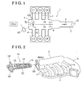
- Fig. 1 is a schematic view illustrating an air intake system of a multi-cylinder internal combustion engine according to an embodiment disclosed here;
- Fig. 2 is a perspective view illustrating a state where an air intake control valve is attached to a surge tank according to the embodiment
- Fig. 3 is a cutaway front view schematically illustrating the air intake control valve mounted on the surge tank;
- Fig. 4 is a schematic plan view illustrating the air intake control valve and a seal member
- Fig. 5A is a side view of an outer peripheral seal member
- Fig. 5B is a plan view of the outer peripheral seal member:
- Figs. 5C, 5D, 5E, 5F, 5G, and 5H are cross-sectional views taken along the lines 5C-5C, 5D-5D, 5E-5E, 5F-5F, 5G-5G, and 5H-5H in Fig. 5A and illustrating first, second, third, fourth, fifth, and sixth pattern portions of the outer peripheral seal member respectively;
- Figs. 6A, 6B, and 6C are cross-sectional views illustrating operations of the outer peripheral seal member
- Fig. 7 is a plan view illustrating an operation of the outer peripheral seal member at a portion close to a tip end portion of the air intake control valve
- Figs. 8A and 8B are cross-sectional views illustrating operations of the outer peripheral seal member according to another embodiment.
- Figs. 9A and 9B are cross-sectional views illustrating operations of a seal member according to a known air intake control valve.
- FIG. 1 illustrates a relationship between an air intake system 1 for a V-type 6-cylinder engine (hereinafter simply referred to as an engine), and six cylinders C1, C2, C3, C4, C5, and C6 (hereinafter referred to as cylinders C1 to C6 when collectively described).
- the air intake system 1 includes an air intake passage 3 supplied with air taken in through an air filter, and a surge tank 5 disposed between the air intake passage 3 and the cylinders C1 to C6.
- a throttle valve 2 is provided at the air intake passage 3.
- the surge tank 5 is divided into first and second surge chambers 7a and 7b by means of a partition wall 6.
- the cylinders C1, C3, and C5 are connected to the first chamber 7a provided at an upper side in Fig. 1 via respective intake pipes 4.
- the cylinders C2, C4, and C6 are connected to the second surge chamber 7b provided at a lower side in Fig. 2 via the respective intake pipes 4.
- a resonance of a manifold air pressure is generated at a predetermined engine rotational range.
- Such resonance is generated in a case where a frequency (a resonance frequency) that is determined on a basis of a volume, a length, and the like of the surge tank 5 and/or the air intake passage 3 provided at an upstream side of the surge tank 5, for example, and an intake air frequency of the cylinders C1 to C6 match each other.
- a pressure at the air intake system 1 increases, which leads to a supercharging effect. Because of the supercharging effect, an intake air volume of each of the cylinders C1 to C6 increases to thereby improve an engine output.
- an air intake control valve 10 is provided at the air intake system 1 so as to achieve an open state where the first and second surge chambers 7a and 7b are connected to each other and a closed state where the first and second surge chambers 7a and 7b are disconnected to each other.
- the resonance frequency of the air intake system 1 changes.
- the air intake control valve 10 is appropriately controlled to open or close depending on an operation condition of the engine to thereby change the resonance frequency of the air intake system 1 and obtain the supercharging effect.
- the increase of the engine output at a wide range of the engine rotational range is achievable.
- the first surge chamber 7a provided at the upper side and the second surge chamber 7b provided at the lower side are connected to each other by means of a cutout 6p formed at a portion of the partition wall 6.
- the air intake control valve 10 that is enlarged so as to improve the supercharging effect is mounted on the cutout 6p.
- An actuator 40 for opening and closing the air intake control valve 10 may be an electrically controlled type so as to be driven by an electric signal sent from an ECU (an electronic control unit) that is mounted at a vehicle.
- the pressure is alternately generated at the first and second surge chambers 7a and 7b that are arranged next to each other via the partition wall 6 because the air intake is sequentially performed by the cylinders C1 to C6.
- a fluid leakage may occur between the cutout 6p and the air intake control valve 10 while the air intake control valve 10 is in the closed state, for example, an expected resonance frequency is not obtained at the air intake system 1, which leads to a deterioration of the supercharging effect.
- the air intake control valve 10 includes a body 12 attached to the cutout 6p of the partition wall 6 and a valve element 14 supported by a shaft 15. Both ends of the shaft 15 are pivotally supported by respective portions of the body 12.
- the body 12 is formed into a frame shape extending along the cutout 6p of the partition wall 6.
- a fluid passage 10A is formed at an inner side of the frame shape of the body 12.
- a seal receiving portion 13 is formed at an inner peripheral surface of the body 12 so as to extend within the fluid passage 10A.
- the seal receiving portion 13 extends over a substantially entire inner periphery of the body 12.
- the closed position of the valve element 14 is illustrated by a solid line while the open position of the valve element 14 is illustrated by a chain double-dashed line.
- the valve element 14 includes a valve body 16 attached to the shaft 15 and formed into a resin-made plate shape, and an elastic seal member 17 arranged at a peripheral edge of the valve body 16 and made of rubber.
- the elastic seal member 17 includes an attachment portion 18 fitted to an outer periphery of the valve body 16 and a lip portion 19 projecting from a portion of a peripheral edge of the attachment portion 18 so as to incline close to a center of the valve element 14.
- the lip portion 19 is connected to a portion of an outer periphery of the attachment portion 18 so as to extend and incline towards the center of the valve element 14.
- the actuator 40 brings the valve element 14 to rotate so as to obtain the open state (open position) where the first and second surge chambers 7a and 7b are connected (i.e., the open state of the fluid passage 10A) and obtain the closed state (closed position) where the first and second surge chambers 7a and 7b are disconnected (i.e., the closed state of the fluid passage 10A).
- the lip portion 19 is pressed against the seal receiving portion 13 to thereby disconnect the first and second surge chambers 7a and 7b from each other.
- the air intake control valve 10 is inserted into an opening portion 5A formed at the surge tank 5 opposite from the air intake passage 3 so as to be fixed to the surge tank 5 by means of a bolt, for example, that is inserted into a through-hole formed at a flange 10F of the air intake control valve 10.
- a bolt for example
- an inner portion of the surge tank 5 is divided into two portions, i.e., the first surge chamber 7a and the second surge chamber 7b, by mean of the body 12 of the air intake control valve 10. That is, the body 12 serves as a divided surface to divide the inner portion of the surge tank 5 into the two portions.
- a sheet surface of Fig. 4 corresponds to the divided surface.
- an outer peripheral seal member (a gasket) 20 (serving as an example of a seal member) formed into a strip shape and made of rubber is attached to an outer periphery of the body 12.
- a gasket serving as an example of a seal member
- a gap between the body 12 and an end surface 6f (serving as an example of a sealed surface) of the cutout 6p of the surge tank 5 is filled with the outer peripheral seal member 20, which leads to a high sealability.
- the outer peripheral seal member 20 includes a center portion 20A attached to a tip end portion of the body 12 (i.e., a portion of the body 12 away from the flange 10F) and two side portions 20B extending from both ends of the center portion 20A.
- a center portion 20A attached to a tip end portion of the body 12 (i.e., a portion of the body 12 away from the flange 10F)
- two side portions 20B extending from both ends of the center portion 20A.
- ranges where the two side portions 20B are arranged are indicated by arrows E respectively.
- Figs. 5A and 5B are a side view and a plan view of the outer peripheral seal member 20 respectively in which the two side portions 20B extend along the divided surface constituted by the body 12 so as to be linear relative to the center portion 20A.
- the center portion 20A in the side view and the plan view is formed so that a width thereof is larger than those of the two side portions 20B.
- the outer peripheral seal member 20 before being attached to the body 12 is substantially formed into a linear shape as illustrated in Figs. 5A and 5B . Then, the outer peripheral seal member 20 is attached to the body 12 in a state to be elastically deformed in a curved shape so as to conform to a shape of the body 12 as illustrated in Fig. 4 .
- the center portion 20A engages with the surge tank 5 so that a groove (a clearance) 24 formed at an outer periphery of the center portion 20A engages with an engagement projection 6Q that projects towards the opening portion 5A from the end surface 6f of the cutout 6p as illustrated in Fig. 7 .
- a projection such as the engagement projection 6Q is not formed at a portion of the end surface 6f positioned to face each of the two side portions 20B.
- a pair of first contact portions 23d basically formed into a Y-shape while having an opening as illustrated in Fig.
- contact portions such as the contact portions 23d are portions which are contactable with the end surface 6f in association with an increase of a pressure in each of the surge chambers 7a and 7b after the air intake control valve 10 is mounted to the surge tank 5 and the engine is started.
- a greater portion of the two side portions 20B is constituted by first pattern portions S1 each having a cross-sectional shape as illustrated in Fig. 5C and second pattern portions S2 each having a cross-sectional shape as illustrated in Fig. 5D .
- the first pattern portions S1 and the second pattern portions S2 are alternately arranged to one another.
- each of the first pattern portions S1 includes a first fitting portion 21 d (serving as an example of a supported portion) fitted to a seal groove 12D (see Fig. 6A ) of the body 12 and substantially formed into a rectangular shape.
- the first pattern portion S1 also includes a pair of first intermediate portions 22d extending in parallel to each other towards the end surface 6f from both ends (i.e., right and left ends in Fig. 5C ) of the first fitting portion 21d, and the pair of first contact portions 23d extending so as to be away or opposite from each other relative to the divided surface constituted by the body 12 from ends (i.e., upper ends of the first intermediate portions 22d in Fig. 5C ) of the respective first intermediate portions 22d.
- the first contact portions 23d extend obliquely in an upward direction so as to be away from each other (i.e., extend obliquely in an upward and outward direction relative to the divided surface) in a symmetric manner.
- each of the second pattern portions S2 includes a second fitting portion 21f (serving as an example of the supported portion) fitted to the seal groove 12D of the body 12 and substantially formed into a rectangular shape.
- the second pattern portion S2 also includes a pair of second intermediate portions 22f extending in parallel to each other towards the end surface 6f from both ends (i.e., right and left ends in Fig. 5D ) of the second fitting portion 21f, and a pair of second contact portions 23f extending so as to be away or opposite from each other relative to the divided surface constituted by the body 12 from ends (i.e., upper ends of the second intermediate portions 22f in Fig. 5D ) of the respective second intermediate portions 22f.
- the second contact portions 23f extend obliquely in an upward direction so as to be away from each other (i.e., extend obliquely in an upward and outward direction relative to the divided surface) in a symmetric manner.
- Each of the first pattern portions S1 and each of the second pattern portions S2 basically include the same cross-sectional shape.
- the difference between the first and second pattern portions S1 and S2 is that padding portions 21A are formed at both sides (i.e., right and left sides in Fig. 5D ) of the second fitting portion 21f of the second pattern portion S2 so as to have a larger width than the first fitting portion 21 d of the first pattern portion S1.
- a width of a portion of the seal groove 12D of the body 12 facing the two side portions 20B is constant over an entire length.
- the two side portions 20B engage with the body 12 in a state where the second fitting portion 21f of each of the second pattern portions S2 of which the width is sufficiently larger than the width of the seal groove 12D is press-fitted to the seal groove 12D.
- the width of the first fitting portion 21d of each of the first pattern portions S1 is formed to be slightly smaller than the width of the seal groove 12D. Therefore, the first fitting portion 21d engages with the seal groove 12D without the press-fitting.
- the outer peripheral seal member 20 is mounted to the body 12 in a state where the first fitting portions 21 d of the first pattern portions S1 in addition to the second fitting portions 21f of the second pattern portions S2 are pressed against a bottom portion of the seal groove 12D, an air leakage via lower surfaces of the first and second fitting portions 21d and 21f is inhibited.
- the pair of first contact portions 23d extends so as to be away from each other relative to the divided surface constituted by the body 12, i.e., extends obliquely in an outward direction.
- the pair of second contact portions 23f extends so as to be away from each other relative to the divided surface, i.e., extends obliquely in the outward direction.
- the width of each of the first intermediate portions 22d and the first contact portions 23d is formed to be sufficiently smaller than the width of the first fitting portion 21 d while the width of each of the second intermediate portions 22f and the second contact portions 23f is formed to be sufficiently smaller than the width of the second fitting portion 21d.
- the first intermediate portions 22d, the second intermediate portions 22f, the first contact portions 23d, and the second contact portions 23f are easily elastically deformed so as to be inclined towards the body 12 in respective directions based on the contact of the first intermediate portions 22d, the second intermediate portions 22f, the first contact portions 23d, and the second contact portions 23f relative to the end surface 6f.
- the air intake control valve 10 is smoothly inserted and mounted to the surge tank 5.
- the groove 24 having a sufficient width is formed between each of the pair of first intermediate portions 22d and the pair of second intermediate portions 22f.
- the width of each of the pair of first intermediate portions 22d and the pair of second intermediate portions 22f (each serving as an example of a deformation portion) is specified to be smaller than the width of a base portion of each of the pair of first contact portions 23d and the pair of second contact portions 23f. That is, each of the pair of first intermediate portions 22d and the pair of second intermediate portions 22f has a low rigidity.
- each of the pair of first contact portions 23d and the pair of second contact portions 23f has a high rigidity because of being gradually widen from a tip end portion to the base portion.
- the pair of first contact portions 23d and the pair of second contact portions 23f are not easily deformed. Therefore, in a case where the air intake control valve 10 is inserted and mounted to the surge tank 5, the pair of first intermediate portions 22d and the pair of second intermediate portions 22f are elastically deformed by making contact with the end surface 6f prior to the other members. The pair of first contact portions 23d and the pair of second contact portions 23f are not easily deformed except for the tip end portions.
- the contact of the outer peripheral seal member 20 relative to the end surface 6f in a case where the air intake control valve 10 is inserted and mounted to the surge tank 5 is limited to portions at inner sides of the first and second contact portions 23d and 23f in the vicinity of the tip end portions thereof. That is, a contact area of the outer peripheral seal member 20 relative to the end surface 6f is minimized and therefore the insertion load of the air intake control valve 10 decreases, which leads to an easy insertion and mounting of the air intake control valve 10. As a result, productivity increases, which may avoid an investment in facility for a large insertion load of the air intake control valve 10. In addition, because of the decrease of the insertion load, a quality defect such as a dislocation of the outer peripheral seal member 20 when the air intake control valve 10 is assembled to the surge tank 5 is avoidable.
- the first and second contact portions 23d and 23f (each serving as an example of a seal portion) are pressed against the end surface 6f of the partition wall 6 by means of a relatively weak restoring force of the first and second intermediate portions 22d and 22f.
- an air intake pulsation is alternately applied to the first and second surge chambers 7a and 7b.
- a greater part of the first contact portions 23d (and the second contact portions 23f) facing the first and second surge chambers 7a and 7b is strongly pressed against the cutout 6p (the end surface 6f).
- the sealing ability is automatically enhanced and the high air tightness is maintained.
- the width of each of the tip end portions of the first and second contact portions 23d and 23f (each serving as an example of the deformation portion) is relatively small so that the first and second contact portions 23d and 23f are easily elastically deformed by the contact with the cutout 6p (the end surface 6f).
- Bottom plane portions of the grooves 24 respectively provided between the first intermediate portions 22d and between the second intermediate portions 22f are each formed into a solid shape while including a large amount of rubber so as to have a large rigidity. Accordingly, in a case where the outer peripheral seal member 20 is assembled on the seal groove 12D of the body 12, the load is applied to the bottom plane portions of the grooves 24 so that a damage, breakage or the like on each of the first and second contact portions 23c, 23d, the first and second intermediate portions 22d, 22f, and the like is inhibited.
- Both side corners (i.e., right and left corners in Figs. 6A, 6B, and 6C ) of each of the grooves 24 are formed into round cross sectional shapes each including an arc relative to a center of a void of the groove 24.
- a stress generated when each of the first and second intermediate portions 22d and 22f is deformed is dispersed.
- a fatigue resistance of each of the first and second contact portions 23d, 23f, and the first and second intermediate portions 22d and 22f increases.
- a reduction in an amount of rubber of the outer peripheral seal member 20 and a cost reduction thereof are achieved as well as a light-weight of the outer peripheral seal member 20 as a whole.
- a curvature radius of each curved portion of the body 12 positioned to face a portion of each of the two side portions 20B in the vicinity of the center portion 20A is small.
- the bent portions of the two side portions 20B in the vicinity of the center portion 20A are bent and deformed so as to conform to the curvature radius of the curved portions of the body 12.
- the first and second contact portions 23d and 23f may be folded down toward the body 12, which may inhibit the appropriate contact relative to the cutout 6p after the air intake control valve 10 is mounted to the surge tank 5.
- the tip ends of the pair of first contact portions 23d are arranged so as to be close to each other in association with the decrease of the curvature radius.
- the tip ends of the pair of second contact portions 23f are arranged so as to be close to each other in association with the decrease of the curvature radius.
- the first contact portions 23d and the second contact portions 23f in the bent portions of the two side portions 20B are appropriately bent or inclined towards the body 12 so that a distance between the tip ends of the first contact portions 23d and a distance between the tip ends of the second contact portions 23f in the bent portions of the two side portions 20B are each substantially equal to a distance between the contact portions 23d or 23f in portions other than the bent portions (i.e., straight portions) of the two side portion 20B.
- the appropriate contact of the outer peripheral seal member 20 relative to the end surface 6f is achieved.
- an angle formed between the first contact portions 23d and an angle formed between the second contact portions 23f are each defined to be small.
- the aforementioned angles may not be changed and a distance between the first intermediate portions 22d and a distance between the second intermediate portions 22f may be reduced.
- an extending length of each of the first contact portions 23d and the second contact portions 23f in the bent portions of the two side portions 20B may be longer than the extending length of each of the first and second contact portions 23d and 23f in the straight portions of the two side portions 20B in a state before the outer peripheral seal member 20 is bent and deformed.
- fourth pattern portions S4 are provided at most end portions of the two side portions 20B respectively.
- Each of the fourth pattern portions S4 is formed into a cross-sectional shape similar to that of the second pattern portion S2 but the groove 24 and a gap (a space) between the second contact portions 23f are eliminated.
- third pattern portions S3 are provided, each of which is arranged between two of the first pattern portions S1 arranged close to the center of the outer peripheral seal member 20 relative to the fourth pattern portions S4.
- Each of the third pattern portions S3 includes a third fitting portion 21e of which the width is larger than the second fitting portion 21f of the second pattern portion S2, a pair of third intermediate portions 22e, and a pair of third contact portions 23e.
- the third fitting portion 21e serves as an example of the supported portion while the third contact portions 23e each serves as an example of the seal portion.
- the third pattern portions S3 serve as engagement portions inserted and fitted to respective lock grooves 12E (see Fig. 4 ) formed at two portions of the body 12 in the vicinity of a base portion thereof (i.e., a portion of the body 12 close to the flange 10F) as illustrated in Fig. 4 .
- the lock grooves 12E are arranged slightly closer to the flange 10F as compared to a distance from a center of the outer peripheral seal member 20 (which corresponds to a 5H-5H plane in Fig. 5A ) in a longitudinal direction thereof to each of the third pattern portions S3 in a state where the external force is not applied to the outer peripheral seal member 20.
- Hardness and strength of a rubber material constituting the outer peripheral seal member 20 are defined to be relatively high so as to respond to alcohol fuel.
- a reaction force (a rubber reaction force) generated at portions of the outer peripheral seal member 20 attached to corner portions of the body 12 each having a U-shape is relatively large so as to return to an original linear shape.
- the positions of the lock grooves 12E are defined in the aforementioned manner as the tightening and fitting means, thereby effectively restraining a lifting-up, disengagement, or the like of the outer peripheral seal member 20 by the rubber reaction force, because of a tensile force maintained at the outer peripheral seal member 20 after the outer peripheral seal member 20 is attached to the body 12.
- the tightening and fitting means may be provided between the both ends of the center portion 20A and the body 12.
- the tightening and fitting means provided at four portions or more of the outer peripheral seal member 20 may effectively inhibit the disengagement of the outer peripheral seal member 20 from the body 12 caused by the rubber reaction force of the outer peripheral seal member 20. Further, the tightening and fitting means provided at four or more portions in an asymmetrical manner may inhibit a wrong assembly.
- the positions of the lock groves 12E are specified in the aforementioned manner so that the first intermediate portions 22d of the first pattern portions S1 engage with the tip end portion of the body 12, and then the third pattern portions S3 are inserted and fitted to the lock grooves 12E. Then, the second fitting portions 21f of the second pattern portions S2 are inserted and fitted to the seal groove 12D one by one, which leads to an easy assembly of the outer peripheral seal member 20.
- the fourth pattern portions S4 provided at the most end portions of the outer peripheral seal member 20 respectively form ribs (specifically, each of the fourth pattern portions S4 has a rib portion 25) while having no grooves or spaces, thereby being connected to the respective adjacent first pattern portions S1.
- the fourth pattern portions S4 restrain the air leakage from one of the first and second surge chambers 7a and 7b to the other of the first and second surge chambers 7a and 7b via spaces such as those between the contact portions and between the intermediate portions.
- the fourth pattern portions S4 constituting the ribs may not be only provided at the both end portions of the outer peripheral seal member 20 but also provided at any other portions of the outer peripheral seal member 20.
- ribs i.e., the fourth pattern portions S4 restrain the contact portions 23d, 23e and 23f from being inclined or folded because of a pressure difference between the first and second surge chambers 7a and 7b. As a result, the high sealing ability is maintained even under a pressure pulsation.
- a groove having a tunnel shape may be intermittently formed at the bottom surface of the outer peripheral seal member 20. As a result, the reduction of the amount of rubber and the light-weight of the outer peripheral seal member 20 as a whole are further enhanced.
- a distance between the fourth pattern portion S4 forming the rib and the adjacent third pattern portion S3 is specified to be slightly longer than a length of a corresponding portion of the groove 12D formed at the body 12 in a state where the outer peripheral seal member 20 is in the linear shape. Therefore, both end surfaces of the both end portions of the outer peripheral seal member 20 are elastically pressed against the end surface of the flange 10F of the body 12. The air leakage between the first and second surge chambers 7a and 7b at the both end portions of the outer peripheral seal member 20 is inhibited, which ensures the further high sealing ability.
- the groove 24 formed at a fifth pattern portion S5 that occupies a majority of the length of the center portion 20A includes a pair of side surface portions 25i engaging with the engagement projection 6Q that projects from the body 12.
- the fifth pattern portion S5 includes a center projection 20T having an arc-shape in a plan view and formed at a center of the outer peripheral seal member 20 in the longitudinal direction thereof.
- Fig. 5H illustrates a cross section of a portion corresponding to the center projection 20T.
- An area sandwiched between two dashed lines in Fig. 5H illustrates a cross-sectional shape of the fifth pattern portion S5 not provided with the center projection 20T.
- a wide-shaped portion is formed at the seal groove 12D of the body 12 so as to correspond to the center projection 20T.
- the center projection 20T engages with the wide-shaped portion of the body 12 so as to perform a centering of the outer peripheral seal member 20 in the longitudinal direction.
- Sixth pattern portions S6 smoothly connect the fifth pattern portion S5 having the wide shape to the two side portions 20B each having the narrow shape.
- the engagement projection 6Q is inserted and fitted to the groove 24 of each of the sixth pattern portions S6 so that the sixth pattern portion S6 engages with the engagement projection 6Q in the vicinity of a boundary between intermediate portions 22g and contact portions 23g of the sixth pattern portion S6. Accordingly, the fifth pattern portion S5 and the sixth pattern portions S6 are fitted to or engage with the engagement projection 6Q to thereby appropriately and correctly position the center portion 20A relative to the body 12 in a direction perpendicular to the divided surface constituted by the body 12.
- a vertical vibration or a rotational vibration of the body 12 in the vicinity of the tip end portion thereof is large because of a vibration or a pulsation pressure difference applied to the valve element 14 or the body 12 that supports the valve element 14.
- the engagement projection 6Q is fitted to the grooves 24 each having a U-shape that are formed at the center portion 20A of the outer peripheral seal member 20, thereby restraining the vibration of the body 12.
- the air intake control valve 10 is mounted to the surge tank 5
- a self-centering of the air intake control valve 10 relative to the cutout 6p of the surge tank 5 is achieved because of the fitting between the grooves 24 and the engagement projection 6Q.
- the outer peripheral seal member 20 is provided, no direct contact is obtained between the body 12 and the end surface 6f, thereby inhibiting a malfunction such as an interfering noise.
- the pair of first contact portions 23d of each of the first pattern portions S1 may be arranged in parallel to each other
- the pair of second contact portions 23f of each of the second pattern portions S2 may be arranged in parallel to each other
- the third contact portions 23e of each of the third pattern portions S3 may be arranged in parallel to each other as in the same way as the pair of first intermediate portions 22d, the pair of second intermediate portions 22f, and the pair of third intermediate portions 22e while the contact portions 23d, 23e, and 23f are each in a natural state so as not to receive the external force.
- the first to third contact portions 23d, 23f, and 23e may be deformed to be positioned closer to the body 12 by hand or by a jig so as to be mounted to the body 12 of the air intake control valve 10.
- the single first intermediate portion 22d may extend from the first fitting portion 21 d
- the single second intermediate portion 22f may extend from the second fitting portion 21f
- the single third intermediate portion 22e may extend from the third fitting portion 21e.
- the pair of first contact portions 23d may extend from an end of the single first intermediate portion 22d in a direction opposite from each other relative to the divided surface constituted by the body 12.
- the pair of second contact portions 23f may extend from an end of the single second intermediate portion 22f in a direction opposite from each other relative to the divided surface constituted by the body 12.
- the pair of third contact portions 23e may extend from an end of the single third intermediate portion 22e in a direction opposite from each other relative to the divided surface constituted by the body 12.
- one of a pair of intermediate portions 52 and one of a pair of contact portions 53, and the other of the pair of intermediate portions 52 and the other of the pair of contact portions 53 may extend from both side edges at an upper portion of a fitting portion 51 so as to form an arc shape towards a center line of the outer peripheral seal member 20.
- a projection 6R is formed at the end surface 6f of the partition wall 6 so as to extend along the two side portions 20B.
- outer side surfaces of the pair of contact portions 53 are pressed against the end surface 6f as illustrated in Fig. 8B .
- the ends of the pair of contact portions 53 are pressed against corners each formed between a side surface of the projection 6R and the end surface 6f, thereby maintaining the air sealed state.
- the tip ends of the first contact portions 23d are arranged to be close to each other in association with the increase of the curvature radius of the curved portions of the body 12 in a state before the outer peripheral seal member 20 is bent and deformed.
- the tip ends of the second contact portions 23f are arranged to be close to each other in association with the increase of the curvature radius of the curved portions of the body 12 in a state before the outer peripheral seal member 20 is bent and deformed.
- the tip ends of the second contact portions 23f are arranged to be close to each other in association with the increase of the curvature radius of the curved portions of the body 12 in a state before the outer peripheral seal member 20 is bent and deformed.
- the tip ends of the contact portions 53 may be arranged to be away from each other in association with the decrease of the curvature radius in a state before the outer peripheral seal member 20 is bent and deformed. Then, when the two side portions 20B are bent and deformed so as to mount the outer peripheral seal member 20 to the body 12, the contact portions 53 are appropriately bent towards the body 12. As a result, a distance between the two contact portions 53 in the bent portions of the two side portions 20B is substantially equal to a distance between the two contact portions 53 in the straight portions of the two side portions 20B, thereby obtaining an appropriate contact state relative to the end surface 6f.
Landscapes
- Engineering & Computer Science (AREA)
- Chemical & Material Sciences (AREA)
- Combustion & Propulsion (AREA)
- Mechanical Engineering (AREA)
- General Engineering & Computer Science (AREA)
- Manufacturing & Machinery (AREA)
- Characterised By The Charging Evacuation (AREA)
Abstract
Description
- This disclosure generally relates to an air intake control valve.
- In a multi-cylinder internal combustion engine (hereinafter simply referred to as an engine) for a vehicle, for example, an air intake control valve is known to be provided at an air intake system including a port and a surge tank. Such air intake control valve includes a body extending so as to divide an inner portion of the surge tank into two portions, a valve element operated to rotate so as to open and close a fluid passage formed at the body, and a seal member sealing between an inner surface of the surge tank and an outer periphery of the body. The air intake control valve is mounted so as to close a connection bore formed at a partition wall separating the inner portion of the surge tank into the two portions, i.e., two chambers. The valve element of the air intake control valve is appropriately driven to rotate by an actuator so as to obtain a connected state where the two chambers are connected to each other and a disconnected state where the two chambers are disconnected from each other. As a result, a resonance frequency of the air intake system is changed to thereby obtain a supercharging effect over a wide range of an engine operation. In a case where an air leakage increases between the two chambers (upper and lower chambers), an expected resonance frequency may not be obtained in the air intake system of the engine, which leads to a deterioration of the supercharging effect.
-
JP2004-116357A Figs. 9A and 9B in which a gasket (seal member) 67 formed into a string shape and made of an elastic material is attached to an outer periphery of a frame (body) 62 holding a valve element. In a case where thebody 62 is attached to a sealedsurface 66f of a partition wall formed at a surge tank, a gap between the sealedsurface 66f and thebody 62 is sealed by theseal member 67 that is pressed against the sealedsurface 66f of the partition wall. As a result, an air leakage between two chambers (upper and lower chambers) is restrained. - As illustrated in
Fig. 9A , according to the air intake control valve disclosed inReference 1, theseal member 67 includes afitting portion 68 fitted to aseal groove 62D that is formed at the outer periphery of thebody 62. Thefitting portion 68 substantially includes a rectangular cross section. Theseal member 67 also includes anend seal portion 69 vertically extending from thefitting portion 68 towards the sealedsurface 66f. Theend seal portion 69 substantially includes a semicircular cross section symmetric to a divided surface constituted by thebody 62 so as to divide an inner portion of the surge tank into two portions. In a case where thebody 62 is attached to the sealedsurface 66f, theend seal portion 69 is squashed towards thefitting portion 68 by the sealedsurface 66f while the symmetric shape of theend seal portion 69 relative to the divided surface is maintained as illustrated inFig. 9B . According to the aforementioned structure, in order to restrain the air leakage because of the deformation of theend seal portion 69 in an oblique or lateral direction that is caused by a high air pressure from either of the upper and lower chambers, a rigidity to some extents may be required to theend seal portion 69. Therefore, an apex angle of a triangular-shaped cross section constituting theend seal portion 69 may be inhibited from having too acute angle and additionally theend seal portion 69 may be made of a material having relatively high rigidity. - As a result, in a case where the
body 62 is attached to the sealedsurface 66f, a large load is necessary for bringing theend seal portion 69 having the semicircular cross section to be deformed so as to be compressed against thefitting portion 68. A contact area between the sealedsurface 66f and theend seal portion 69 also increases, which may lead to an increase of a contact pressure or a frictional resistance, for example, acting between the sealedsurface 66f and theend seal portion 69. Consequently, the attachment of thebody 62 relative to the sealedsurface 66f may be difficult. - In addition, in a case where the
body 62 is attached to the sealedsurface 66f, thefitting portion 68 of theseal member 67 is likely to disengage from theseal groove 62D formed at the outer periphery of thebody 62 or to be partially pulled out in a direction where thebody 62 is attached because of the high contact pressure, the frictional resistance, and the like acting between the sealedsurface 66f and theend seal portion 69. Thus, the sealing ability of theend seal portion 69 may be deteriorated. Further, thebody 62 may be deformed by a reaction force that is generated at thebody 62 by means of theend seal portion 69, which may lead to the air leakage between thebody 62 and thefitting portion 68 of theseal member 67. - In
Reference 1, theseal member 67 may have an arched shape in a cross section by including agroove portion 70 having a tunnel shape at a lower end of thefitting portion 68 to thereby reduce the reaction force generated at thefitting portion 68 of theseal member 67. However, because of the high rigidity of the material constituting theseal member 67, an easy deformation is insufficient for theentire seal member 67. As a result, a large compression by a low load may be impossible and therefore an issue of an excessive load when thebody 62 is inserted into the sealedsurface 66f may not be effectively dissolved. -
JP63-156422U Reference 1, each of the projections vertically projects towards a sealed surface, which may also raise issues such as a difficulty in attaching the body to the sealed surface, the deterioration of the sealing ability because of the disengagement or the pull-out of a fitting portion of a seal member, an air leakage caused by the deformation of the body, or the like. - A need thus exists for an air intake control valve that sufficiently restrains an air leakage between upper and lower chambers in a fully closed state of the air intake control valve while a contact pressure acting between a sealed surface and an end seal portion is sufficiently reduced so that a body is easily attached to the sealed surface, and a deterioration of a sealing ability based on a disengagement or a pull-out of a fitting portion of a seal member, an air leakage based on a deformation of the body, and the like are unlikely to occur).
- According to an aspect of this disclosure, an air intake control valve includes a body extending to divide an inner portion of a surge tank of a multi-cylinder internal combustion engine into two portions, the body serving as a divided surface to divide the inner portion of the surge tank into the two portions, a valve element operated to rotate for opening and closing a fluid passage formed at the body, and a seal member sealing between a sealed surface of the surge tank and an outer periphery of the body, the seal member including a seal portion constituted by two contact portions that make contact with the sealed surface in a state where the two contact portions extend in directions opposite from each other relative to the divided surface.
- According to the air intake control valve having the aforementioned structure, the two contact portions extend obliquely in an upward direction so as to be away from each other from an initial state before the seal member receives an external force. Thus, in a case where the air intake control valve is inserted and mounted to the surge tank, the two contact portions are bent and deformed so as to be easily positioned close to the body, thereby smoothly mounting the air intake control valve to the surge tank. In addition, because a reaction force applied to the body from the seal member is small in the process of attaching the air intake control valve to the surge tank and after the air intake control valve is attached to the surge tank, the deformation of the body caused by the aforementioned reaction fore is restrained. As a result, an adverse affect on a sealing ability between the body and a cutout of the surge tank, between the body and the valve element of the air intake control valve, and the like based on the deformation of the body may be avoided. After the air intake control valve is mounted to the surge tank, the two contact portions are pressed against the sealed surface by means of a relatively weak restoring force of intermediate portions of the seal member. However, in a state where the valve element of the air intake control valve is in a fully closed state, the sealing ability is automatically enhanced and a high air tightness is maintained because one of the two contact portions facing one of surge chambers having a higher pressure is strongly pressed against the sealed surface by means of an air pressure. In a state where the air intake control valve is mounted to the surge tank, only tip ends of the two contact portions make contact with the sealed surface.
- The seal member includes a supported portion supported by the body and two intermediate portions extending from the supported portion to the sealed surface, and the two contact portions extend from the two intermediate portions respectively.
- Accordingly, the two intermediate portions in addition to the two contact portions are elastically deformed towards the body by the contact with the sealed surface in the case of attaching the air intake control valve to the surge tank. Thus, an insertion load is further reduced to thereby further smoothly mounting the air intake control valve to the surge tank. Further, as compared to a case where the two contact portions extend from the single intermediate portion from the supported portion, a fatigue resistance of the seal member increases because a stress amplitude at a base portion of each of the intermediate portions represents a half amplitude.
- The two intermediate portions serve as deformation portions that are initially elastically deformed by a contact with the sealed surface in a case of attaching the air intake control valve to the sealed surface.
- Accordingly, in the case of attaching the air intake control valve to the surge tank, the two intermediate portions connecting the supported portion to the two contact portions are initially elastically deformed prior to the other portions by the contact between the contact portions and the sealed surface. Because the two contact portions are not easily deformed, only the tip ends of the two contact portions make contact with the sealed surface. As a result, a contact area of the seal member relative to the sealed surface is limited to portions in the vicinity of the tip ends of the two contact portions, which leads to a decrease of the insertion load. Productivity is improved and an investment in facility for a large insertion load of the air intake control valve is avoidable. Further, because of the decrease of the insertion load, a quality defect such as a dislocation or disengagement of the seal member when the air intake control valve is assembled to the surge tank is avoidable.
- The two intermediate portions and tip ends of the two contact portions serve as the deformation portions that are easily deformed by the contact with the sealed surface in the case of attaching the air intake control valve to the sealed surface.
- In the case of attaching the air intake control valve to the surge tank, the two intermediate portions connecting the supported portion to the two contact portions, and the tip ends of the two contact portions are easily elastically deformed by the contact with the sealed surface while portions at base sides of the two contact portions and the like are not easily elastically deformed. Thus, in the process of attaching the air intake control valve to the surge tank, only the tip ends of the two contact portions make contact with the sealed surface. As a result, the contact area of the seal member relative to the sealed surface is minimized and the insertion load is recued, which may increase the productivity and avoid the investment in facility for the large insertion load of the air intake control valve. In addition, because of the decrease of the insertion load, a quality defect such as the dislocation or disengagement of the seal member when the air intake control valve is assembled to the surge tank is avoidable. Further, not only the two intermediate portions but also the tip ends of the two contact portions are easily elastically deformed, thereby easily ensure the sealing ability when the surge chambers are in the low pressure.
- The two contact portions extend to gradually open outwardly towards the sealed surface before the air intake control valve is mounted to the surge tank.
- Accordingly, in the process of attaching the air intake control valve to the surge tank, is it not necessary to manually adjust or assist the two contact portions to be bent and deformed in predetermined respective directions. In addition, after the air intake control valve is mounted to the surge tank, the two contact portions make contact with the sealed surface in such a manner that the two contact portions are gradually away from each other while being positioned closer to the sealed surface. Thus, as compared to a case where the two contact portions gradually approach each other while being positioned closer to the sealed surface, one of the contact portions positioned close to either surge chamber having the higher pressure is pressed against the sealed surface by the air pressure, thereby maintaining the high sealing ability.
- The body includes a curved portion curved along the divided surface while the seal member includes a bent portion bent and deformed along the curved portion of the body so as to be mounted to the sealed surface, and wherein a distance between the two contact portions in the bent portion of the seal member varies in association with a decrease of a curvature radius of the curved portion in a state before the bent portion of the seal member is bent and deformed so as to be mounted to the sealed surface.
- In the bent portion of the seal member attached to the curved portion of the body having a small curvature radius, the two contact portions may be folded down towards the body. Thus, after the air intake control valve is mounted to the surge tank, an appropriate contact of the seal member relative to the sealed surface may not be obtained. However, according to the aforementioned structure, in the bent portion of the seal member, the tip ends of the two contact portions are arranged to be close to each other or to be away from each other in association with the decrease of the curvature radius of the curved portion of the body in a sate before the seal member is bent and deformed. Then, in a case where the two contact portions in the bent portion of the seal member are bent and deformed so that the seal member is mounted to the surge tank, the two contact portions are appropriately folded and bent towards the body. Then, the two contact portions in the bent portion of the seal member is positioned to be away from each other by a distance which is substantially the same as a distance by which the two contact portions in a portion other than the bent portion of the seal member is positioned to be away from each other. As a result, the appropriate contact of the two contact portions of the seal member relative to the sealed surface is obtained.
- The body includes a curved portion curved along the divided surface while the seal member includes a bent portion bent and deformed along the curved portion of the body so as to be mounted to the sealed surface, and wherein an extending length of each of the two contact portions increases in association with a decrease of a curvature radius of the curved portion in a state before the bent portion of the seal member is bent and deformed so as to be mounted to the sealed surface.
- In the bent portion of the seal member attached to the curved portion of the body having the small curvature radius, the two contact portions may be folded down towards the body. Thus, after the air intake control valve is mounted to the surge tank, the appropriate contact of the seal member relative to the sealed surface may not be obtained. However, according to the aforementioned structure, in the bent portion of the seal member, the extending length of each of the two contact portions in the bent portion of the seal member may be longer than the extending length of each of the two contact portions in the portion other than the bent portion of the seal member in a state before the seal member is bent and deformed. Therefore, when the seal member is bent and deformed so that the air intake control valve is mounted to the surge tank, the two contact portions are appropriately folded towards the body so that the extending length of each of the two contact portions in the bent portion of the seal member is substantially equal to the extending length of each of the two contact portions in the portion other than the bent portion of the seal member. As a result, the appropriate contact of the two contact portions of the seal member relative to the sealed surface is obtained.
- The foregoing and additional features and characteristics of this disclosure will become more apparent from the following detailed description considered with the reference to the accompanying drawings, wherein:
-
Fig. 1 is a schematic view illustrating an air intake system of a multi-cylinder internal combustion engine according to an embodiment disclosed here; -
Fig. 2 is a perspective view illustrating a state where an air intake control valve is attached to a surge tank according to the embodiment; -
Fig. 3 is a cutaway front view schematically illustrating the air intake control valve mounted on the surge tank; -
Fig. 4 is a schematic plan view illustrating the air intake control valve and a seal member; -
Fig. 5A is a side view of an outer peripheral seal member; -
Fig. 5B is a plan view of the outer peripheral seal member: -
Figs. 5C, 5D, 5E, 5F, 5G, and 5H are cross-sectional views taken along thelines 5C-5C, 5D-5D, 5E-5E, 5F-5F, 5G-5G, and 5H-5H inFig. 5A and illustrating first, second, third, fourth, fifth, and sixth pattern portions of the outer peripheral seal member respectively; -
Figs. 6A, 6B, and 6C are cross-sectional views illustrating operations of the outer peripheral seal member; -
Fig. 7 is a plan view illustrating an operation of the outer peripheral seal member at a portion close to a tip end portion of the air intake control valve; -
Figs. 8A and 8B are cross-sectional views illustrating operations of the outer peripheral seal member according to another embodiment; and -
Figs. 9A and 9B are cross-sectional views illustrating operations of a seal member according to a known air intake control valve. - An embodiment will be explained with reference to the attached drawings.
Fig. 1 illustrates a relationship between anair intake system 1 for a V-type 6-cylinder engine (hereinafter simply referred to as an engine), and six cylinders C1, C2, C3, C4, C5, and C6 (hereinafter referred to as cylinders C1 to C6 when collectively described). Theair intake system 1 includes anair intake passage 3 supplied with air taken in through an air filter, and asurge tank 5 disposed between theair intake passage 3 and the cylinders C1 to C6. Athrottle valve 2 is provided at theair intake passage 3. Thesurge tank 5 is divided into first andsecond surge chambers partition wall 6. The cylinders C1, C3, and C5 are connected to thefirst chamber 7a provided at an upper side inFig. 1 viarespective intake pipes 4. In the same manner, the cylinders C2, C4, and C6 are connected to thesecond surge chamber 7b provided at a lower side inFig. 2 via therespective intake pipes 4. - In the
air intake system 1, a resonance of a manifold air pressure is generated at a predetermined engine rotational range. Such resonance is generated in a case where a frequency (a resonance frequency) that is determined on a basis of a volume, a length, and the like of thesurge tank 5 and/or theair intake passage 3 provided at an upstream side of thesurge tank 5, for example, and an intake air frequency of the cylinders C1 to C6 match each other. When the resonance is generated, a pressure at theair intake system 1 increases, which leads to a supercharging effect. Because of the supercharging effect, an intake air volume of each of the cylinders C1 to C6 increases to thereby improve an engine output. - In order to generate the aforementioned resonance, an air
intake control valve 10 is provided at theair intake system 1 so as to achieve an open state where the first andsecond surge chambers second surge chambers surge tank 5 relative to the cylinders C1 to C6 changes, the resonance frequency of theair intake system 1 changes. Thus, the airintake control valve 10 is appropriately controlled to open or close depending on an operation condition of the engine to thereby change the resonance frequency of theair intake system 1 and obtain the supercharging effect. As a result, the increase of the engine output at a wide range of the engine rotational range is achievable. - The
first surge chamber 7a provided at the upper side and thesecond surge chamber 7b provided at the lower side are connected to each other by means of acutout 6p formed at a portion of thepartition wall 6. The airintake control valve 10 that is enlarged so as to improve the supercharging effect is mounted on thecutout 6p. Anactuator 40 for opening and closing the airintake control valve 10 may be an electrically controlled type so as to be driven by an electric signal sent from an ECU (an electronic control unit) that is mounted at a vehicle. - In a case where the engine is driven while the air
intake control valve 10 is in a fully closed state, the pressure is alternately generated at the first andsecond surge chambers partition wall 6 because the air intake is sequentially performed by the cylinders C1 to C6. When a fluid leakage may occur between thecutout 6p and the airintake control valve 10 while the airintake control valve 10 is in the closed state, for example, an expected resonance frequency is not obtained at theair intake system 1, which leads to a deterioration of the supercharging effect. - As illustrated in
Figs. 2 to 4 , the airintake control valve 10 includes abody 12 attached to thecutout 6p of thepartition wall 6 and avalve element 14 supported by ashaft 15. Both ends of theshaft 15 are pivotally supported by respective portions of thebody 12. Thebody 12 is formed into a frame shape extending along thecutout 6p of thepartition wall 6. Afluid passage 10A is formed at an inner side of the frame shape of thebody 12. As illustrated inFig. 3 , aseal receiving portion 13 is formed at an inner peripheral surface of thebody 12 so as to extend within thefluid passage 10A. Theseal receiving portion 13 extends over a substantially entire inner periphery of thebody 12. InFig. 3 , the closed position of thevalve element 14 is illustrated by a solid line while the open position of thevalve element 14 is illustrated by a chain double-dashed line. - As illustrated in
Fig. 3 , thevalve element 14 includes avalve body 16 attached to theshaft 15 and formed into a resin-made plate shape, and anelastic seal member 17 arranged at a peripheral edge of thevalve body 16 and made of rubber. Theelastic seal member 17 includes anattachment portion 18 fitted to an outer periphery of thevalve body 16 and alip portion 19 projecting from a portion of a peripheral edge of theattachment portion 18 so as to incline close to a center of thevalve element 14. Specifically, thelip portion 19 is connected to a portion of an outer periphery of theattachment portion 18 so as to extend and incline towards the center of thevalve element 14. Theactuator 40 brings thevalve element 14 to rotate so as to obtain the open state (open position) where the first andsecond surge chambers fluid passage 10A) and obtain the closed state (closed position) where the first andsecond surge chambers fluid passage 10A). In a case where thevalve element 14 is in the closed position, thelip portion 19 is pressed against theseal receiving portion 13 to thereby disconnect the first andsecond surge chambers - As illustrated in
Fig. 2 , the airintake control valve 10 is inserted into anopening portion 5A formed at thesurge tank 5 opposite from theair intake passage 3 so as to be fixed to thesurge tank 5 by means of a bolt, for example, that is inserted into a through-hole formed at aflange 10F of the airintake control valve 10. In a case where the airintake control valve 10 is mounted to thesurge tank 5 in the aforementioned manner, an inner portion of thesurge tank 5 is divided into two portions, i.e., thefirst surge chamber 7a and thesecond surge chamber 7b, by mean of thebody 12 of the airintake control valve 10. That is, thebody 12 serves as a divided surface to divide the inner portion of thesurge tank 5 into the two portions. A sheet surface ofFig. 4 corresponds to the divided surface. - As illustrated in
Figs. 2 to 4 , an outer peripheral seal member (a gasket) 20 (serving as an example of a seal member) formed into a strip shape and made of rubber is attached to an outer periphery of thebody 12. In a case where thebody 12 is mounted to thecutout 6p of thesurge tank 5, a gap between thebody 12 and anend surface 6f (serving as an example of a sealed surface) of thecutout 6p of thesurge tank 5 is filled with the outerperipheral seal member 20, which leads to a high sealability. As illustrated inFig. 4 , because thebody 12 substantially has a U-shape, the outerperipheral seal member 20 includes acenter portion 20A attached to a tip end portion of the body 12 (i.e., a portion of thebody 12 away from theflange 10F) and twoside portions 20B extending from both ends of thecenter portion 20A. InFig. 4 , ranges where the twoside portions 20B are arranged are indicated by arrows E respectively. -
Figs. 5A and 5B are a side view and a plan view of the outerperipheral seal member 20 respectively in which the twoside portions 20B extend along the divided surface constituted by thebody 12 so as to be linear relative to thecenter portion 20A. Thecenter portion 20A in the side view and the plan view is formed so that a width thereof is larger than those of the twoside portions 20B. The outerperipheral seal member 20 before being attached to thebody 12 is substantially formed into a linear shape as illustrated inFigs. 5A and 5B . Then, the outerperipheral seal member 20 is attached to thebody 12 in a state to be elastically deformed in a curved shape so as to conform to a shape of thebody 12 as illustrated inFig. 4 . - In a state where the
body 12 is inserted and mounted to thecutout 6p of thesurge tank 5, thecenter portion 20A engages with thesurge tank 5 so that a groove (a clearance) 24 formed at an outer periphery of thecenter portion 20A engages with anengagement projection 6Q that projects towards the openingportion 5A from theend surface 6f of thecutout 6p as illustrated inFig. 7 . On the other hand, a projection such as theengagement projection 6Q is not formed at a portion of theend surface 6f positioned to face each of the twoside portions 20B. A pair offirst contact portions 23d basically formed into a Y-shape while having an opening as illustrated inFig. 6A is pressed against theend surface 6f of thecutout 6p so as to further open as illustrated inFig. 6B to thereby achieve the sealing state. According to the embodiment, contact portions such as thecontact portions 23d are portions which are contactable with theend surface 6f in association with an increase of a pressure in each of thesurge chambers intake control valve 10 is mounted to thesurge tank 5 and the engine is started. - As illustrated in
Fig. 5A , a greater portion of the twoside portions 20B is constituted by first pattern portions S1 each having a cross-sectional shape as illustrated inFig. 5C and second pattern portions S2 each having a cross-sectional shape as illustrated inFig. 5D . The first pattern portions S1 and the second pattern portions S2 are alternately arranged to one another. As illustrated inFig. 5C , each of the first pattern portions S1 includes a firstfitting portion 21 d (serving as an example of a supported portion) fitted to aseal groove 12D (seeFig. 6A ) of thebody 12 and substantially formed into a rectangular shape. The first pattern portion S1 also includes a pair of firstintermediate portions 22d extending in parallel to each other towards theend surface 6f from both ends (i.e., right and left ends inFig. 5C ) of the firstfitting portion 21d, and the pair offirst contact portions 23d extending so as to be away or opposite from each other relative to the divided surface constituted by thebody 12 from ends (i.e., upper ends of the firstintermediate portions 22d inFig. 5C ) of the respective firstintermediate portions 22d. Specifically, thefirst contact portions 23d extend obliquely in an upward direction so as to be away from each other (i.e., extend obliquely in an upward and outward direction relative to the divided surface) in a symmetric manner. - As illustrated in
Fig. 5D , each of the second pattern portions S2 includes a secondfitting portion 21f (serving as an example of the supported portion) fitted to theseal groove 12D of thebody 12 and substantially formed into a rectangular shape. The second pattern portion S2 also includes a pair of secondintermediate portions 22f extending in parallel to each other towards theend surface 6f from both ends (i.e., right and left ends inFig. 5D ) of the secondfitting portion 21f, and a pair ofsecond contact portions 23f extending so as to be away or opposite from each other relative to the divided surface constituted by thebody 12 from ends (i.e., upper ends of the secondintermediate portions 22f inFig. 5D ) of the respective secondintermediate portions 22f. Specifically, thesecond contact portions 23f extend obliquely in an upward direction so as to be away from each other (i.e., extend obliquely in an upward and outward direction relative to the divided surface) in a symmetric manner. - Each of the first pattern portions S1 and each of the second pattern portions S2 basically include the same cross-sectional shape. The difference between the first and second pattern portions S1 and S2 is that
padding portions 21A are formed at both sides (i.e., right and left sides inFig. 5D ) of the secondfitting portion 21f of the second pattern portion S2 so as to have a larger width than the firstfitting portion 21 d of the first pattern portion S1. A width of a portion of theseal groove 12D of thebody 12 facing the twoside portions 20B is constant over an entire length. Therefore, when the outerperipheral seal member 20 is attached to thebody 12, the twoside portions 20B engage with thebody 12 in a state where the secondfitting portion 21f of each of the second pattern portions S2 of which the width is sufficiently larger than the width of theseal groove 12D is press-fitted to theseal groove 12D. On the other hand, the width of the firstfitting portion 21d of each of the first pattern portions S1 is formed to be slightly smaller than the width of theseal groove 12D. Therefore, the firstfitting portion 21d engages with theseal groove 12D without the press-fitting. Because the outerperipheral seal member 20 is mounted to thebody 12 in a state where the firstfitting portions 21 d of the first pattern portions S1 in addition to the secondfitting portions 21f of the second pattern portions S2 are pressed against a bottom portion of theseal groove 12D, an air leakage via lower surfaces of the first and secondfitting portions - Before the outer
peripheral seal member 20 receives an external force, the pair offirst contact portions 23d extends so as to be away from each other relative to the divided surface constituted by thebody 12, i.e., extends obliquely in an outward direction. In the same way, the pair ofsecond contact portions 23f extends so as to be away from each other relative to the divided surface, i.e., extends obliquely in the outward direction. In addition, the width of each of the firstintermediate portions 22d and thefirst contact portions 23d is formed to be sufficiently smaller than the width of the firstfitting portion 21 d while the width of each of the secondintermediate portions 22f and thesecond contact portions 23f is formed to be sufficiently smaller than the width of the secondfitting portion 21d. Thus, in a case of attaching the air intake control valve 10 (the outer peripheral seal member 20) to thesurge tank 5, the firstintermediate portions 22d, the secondintermediate portions 22f, thefirst contact portions 23d, and thesecond contact portions 23f are easily elastically deformed so as to be inclined towards thebody 12 in respective directions based on the contact of the firstintermediate portions 22d, the secondintermediate portions 22f, thefirst contact portions 23d, and thesecond contact portions 23f relative to theend surface 6f. As a result, the airintake control valve 10 is smoothly inserted and mounted to thesurge tank 5. Further, because a reaction force that thebody 12, having a frame shape, receives by the outerperipheral seal member 20 is reduced in the process of mounting or attaching the airintake control valve 10 to thesurge tank 5 or after the airintake control valve 10 is mounted to thesurge tank 5, the deformation of thebody 12 caused by such reaction force is retrained. An adverse affect on the sealing ability between thebody 12 and thecutout 6p, between thebody 12 and thevalve element 14, and the like based on the deformation of thebody 12 may be avoided accordingly. - The
groove 24 having a sufficient width is formed between each of the pair of firstintermediate portions 22d and the pair of secondintermediate portions 22f. Thus, the width of each of the pair of firstintermediate portions 22d and the pair of secondintermediate portions 22f (each serving as an example of a deformation portion) is specified to be smaller than the width of a base portion of each of the pair offirst contact portions 23d and the pair ofsecond contact portions 23f. That is, each of the pair of firstintermediate portions 22d and the pair of secondintermediate portions 22f has a low rigidity. On the other hand, each of the pair offirst contact portions 23d and the pair ofsecond contact portions 23f has a high rigidity because of being gradually widen from a tip end portion to the base portion. As compared to the pair of firstintermediate portions 22d and the pair of secondintermediate portions 22f, the pair offirst contact portions 23d and the pair ofsecond contact portions 23f are not easily deformed. Therefore, in a case where the airintake control valve 10 is inserted and mounted to thesurge tank 5, the pair of firstintermediate portions 22d and the pair of secondintermediate portions 22f are elastically deformed by making contact with theend surface 6f prior to the other members. The pair offirst contact portions 23d and the pair ofsecond contact portions 23f are not easily deformed except for the tip end portions. - According to the aforementioned configuration, the contact of the outer
peripheral seal member 20 relative to theend surface 6f in a case where the airintake control valve 10 is inserted and mounted to thesurge tank 5 is limited to portions at inner sides of the first andsecond contact portions peripheral seal member 20 relative to theend surface 6f is minimized and therefore the insertion load of the airintake control valve 10 decreases, which leads to an easy insertion and mounting of the airintake control valve 10. As a result, productivity increases, which may avoid an investment in facility for a large insertion load of the airintake control valve 10. In addition, because of the decrease of the insertion load, a quality defect such as a dislocation of the outerperipheral seal member 20 when the airintake control valve 10 is assembled to thesurge tank 5 is avoidable. - After the air
intake control valve 10 is mounted to thesurge tank 5, the first andsecond contact portions end surface 6f of thepartition wall 6 by means of a relatively weak restoring force of the first and secondintermediate portions valve element 14 is in the fully closed state, an air intake pulsation is alternately applied to the first andsecond surge chambers Fig. 6C , a greater part of thefirst contact portions 23d (and thesecond contact portions 23f) facing the first andsecond surge chambers cutout 6p (theend surface 6f). Thus, the sealing ability is automatically enhanced and the high air tightness is maintained. In order to ensure the sealing ability in a low pressure state, the width of each of the tip end portions of the first andsecond contact portions second contact portions cutout 6p (theend surface 6f). - Bottom plane portions of the
grooves 24 respectively provided between the firstintermediate portions 22d and between the secondintermediate portions 22f are each formed into a solid shape while including a large amount of rubber so as to have a large rigidity. Accordingly, in a case where the outerperipheral seal member 20 is assembled on theseal groove 12D of thebody 12, the load is applied to the bottom plane portions of thegrooves 24 so that a damage, breakage or the like on each of the first andsecond contact portions 23c, 23d, the first and secondintermediate portions - Both side corners (i.e., right and left corners in
Figs. 6A, 6B, and 6C ) of each of thegrooves 24 are formed into round cross sectional shapes each including an arc relative to a center of a void of thegroove 24. Thus, a stress generated when each of the first and secondintermediate portions second contact portions intermediate portions grooves 24, a reduction in an amount of rubber of the outerperipheral seal member 20 and a cost reduction thereof are achieved as well as a light-weight of the outerperipheral seal member 20 as a whole. - As illustrated in
Fig. 4 , a curvature radius of each curved portion of thebody 12 positioned to face a portion of each of the twoside portions 20B in the vicinity of thecenter portion 20A (i.e., bent portions of the twoside portions 20B) is small. Thus, in a case where the outerperipheral seal member 20 is attached to the outer periphery of thebody 12, the bent portions of the twoside portions 20B in the vicinity of thecenter portion 20A are bent and deformed so as to conform to the curvature radius of the curved portions of thebody 12. Then, the first andsecond contact portions body 12, which may inhibit the appropriate contact relative to thecutout 6p after the airintake control valve 10 is mounted to thesurge tank 5. - Therefore, in the bent portions of the two
side portions 20B, in a state before the bent portions are bent and deformed, the tip ends of the pair offirst contact portions 23d are arranged so as to be close to each other in association with the decrease of the curvature radius. In the same way, in the bent portions of the twoside portions 20B, the tip ends of the pair ofsecond contact portions 23f are arranged so as to be close to each other in association with the decrease of the curvature radius. That is, in a case where the twoside portions 20B are bent and deformed so that the outerperipheral seal member 20 is mounted to thebody 12, thefirst contact portions 23d and thesecond contact portions 23f in the bent portions of the twoside portions 20B are appropriately bent or inclined towards thebody 12 so that a distance between the tip ends of thefirst contact portions 23d and a distance between the tip ends of thesecond contact portions 23f in the bent portions of the twoside portions 20B are each substantially equal to a distance between thecontact portions side portion 20B. As a result, the appropriate contact of the outerperipheral seal member 20 relative to theend surface 6f is achieved. - Specifically, in order to arrange the
first contact portions 23d to be close to each other and thesecond contact portions 23f to be close to each other, an angle formed between thefirst contact portions 23d and an angle formed between thesecond contact portions 23f are each defined to be small. Alternatively, the aforementioned angles may not be changed and a distance between the firstintermediate portions 22d and a distance between the secondintermediate portions 22f may be reduced. Further alternatively, instead of arranging the tip ends of thefirst contact portions 23d to be close to each other and the tip ends of thesecond contact portions 23f to be close to each other, an extending length of each of thefirst contact portions 23d and thesecond contact portions 23f in the bent portions of the twoside portions 20B may be longer than the extending length of each of the first andsecond contact portions side portions 20B in a state before the outerperipheral seal member 20 is bent and deformed. Further alternatively, a state where the tip ends of thefirst contact portions 23d are arranged to be close to each other and the tip ends of thesecond contact portions 23f are arranged to be close to each other in the bent portions of the twoside portions 20B, and a state where the extending length of each of the first andsecond contact portions side portions 20B are larger than the extending length of each of the first andsecond contact portions side portions 20B may be applied at the same time. - As illustrated in
Figs. 5A and 5F , fourth pattern portions S4 are provided at most end portions of the twoside portions 20B respectively. Each of the fourth pattern portions S4 is formed into a cross-sectional shape similar to that of the second pattern portion S2 but thegroove 24 and a gap (a space) between thesecond contact portions 23f are eliminated. In addition, as illustrated inFigs. 5A and 5E , third pattern portions S3 are provided, each of which is arranged between two of the first pattern portions S1 arranged close to the center of the outerperipheral seal member 20 relative to the fourth pattern portions S4. Each of the third pattern portions S3 includes a thirdfitting portion 21e of which the width is larger than the secondfitting portion 21f of the second pattern portion S2, a pair of thirdintermediate portions 22e, and a pair ofthird contact portions 23e. The thirdfitting portion 21e serves as an example of the supported portion while thethird contact portions 23e each serves as an example of the seal portion. - The third pattern portions S3 serve as engagement portions inserted and fitted to
respective lock grooves 12E (seeFig. 4 ) formed at two portions of thebody 12 in the vicinity of a base portion thereof (i.e., a portion of thebody 12 close to theflange 10F) as illustrated inFig. 4 . Thelock grooves 12E are arranged slightly closer to theflange 10F as compared to a distance from a center of the outer peripheral seal member 20 (which corresponds to a 5H-5H plane inFig. 5A ) in a longitudinal direction thereof to each of the third pattern portions S3 in a state where the external force is not applied to the outerperipheral seal member 20. - Then, in a case of attaching the outer
peripheral seal member 20 to the outer periphery of thebody 12, the firstintermediate portions 22d of the first pattern portions S1 of the outerperipheral seal member 20 are brought to engage with the tip end portion of thebody 12. Then, both of the end portions of the outerperipheral seal member 20 are pulled by a force exceeding a predetermined value in a direction of theflange 10F so that the thirdfitting portions 21 e of the third pattern portions S3 are fitted to thelock grooves 12E to thereby realize a tightening and fitting means. - Hardness and strength of a rubber material constituting the outer
peripheral seal member 20 are defined to be relatively high so as to respond to alcohol fuel. Thus, a reaction force (a rubber reaction force) generated at portions of the outerperipheral seal member 20 attached to corner portions of thebody 12 each having a U-shape is relatively large so as to return to an original linear shape. However, the positions of thelock grooves 12E are defined in the aforementioned manner as the tightening and fitting means, thereby effectively restraining a lifting-up, disengagement, or the like of the outerperipheral seal member 20 by the rubber reaction force, because of a tensile force maintained at the outerperipheral seal member 20 after the outerperipheral seal member 20 is attached to thebody 12. - In order to inhibit the disengagement of the
center portion 20A from thebody 12, the tightening and fitting means may be provided between the both ends of thecenter portion 20A and thebody 12. The tightening and fitting means provided at four portions or more of the outerperipheral seal member 20 may effectively inhibit the disengagement of the outerperipheral seal member 20 from thebody 12 caused by the rubber reaction force of the outerperipheral seal member 20. Further, the tightening and fitting means provided at four or more portions in an asymmetrical manner may inhibit a wrong assembly. - The positions of the
lock groves 12E are specified in the aforementioned manner so that the firstintermediate portions 22d of the first pattern portions S1 engage with the tip end portion of thebody 12, and then the third pattern portions S3 are inserted and fitted to thelock grooves 12E. Then, the secondfitting portions 21f of the second pattern portions S2 are inserted and fitted to theseal groove 12D one by one, which leads to an easy assembly of the outerperipheral seal member 20. - The fourth pattern portions S4 provided at the most end portions of the outer
peripheral seal member 20 respectively form ribs (specifically, each of the fourth pattern portions S4 has a rib portion 25) while having no grooves or spaces, thereby being connected to the respective adjacent first pattern portions S1. The fourth pattern portions S4 restrain the air leakage from one of the first andsecond surge chambers second surge chambers peripheral seal member 20 but also provided at any other portions of the outerperipheral seal member 20. The aforementioned ribs (i.e., the fourth pattern portions S4) restrain thecontact portions second surge chambers peripheral seal member 20 to theseal groove 12D, a groove having a tunnel shape may be intermittently formed at the bottom surface of the outerperipheral seal member 20. As a result, the reduction of the amount of rubber and the light-weight of the outerperipheral seal member 20 as a whole are further enhanced. - A distance between the fourth pattern portion S4 forming the rib and the adjacent third pattern portion S3 is specified to be slightly longer than a length of a corresponding portion of the
groove 12D formed at thebody 12 in a state where the outerperipheral seal member 20 is in the linear shape. Therefore, both end surfaces of the both end portions of the outerperipheral seal member 20 are elastically pressed against the end surface of theflange 10F of thebody 12. The air leakage between the first andsecond surge chambers peripheral seal member 20 is inhibited, which ensures the further high sealing ability. - The
groove 24 formed at a fifth pattern portion S5 that occupies a majority of the length of thecenter portion 20A includes a pair ofside surface portions 25i engaging with theengagement projection 6Q that projects from thebody 12. As illustrated inFig. 5B , the fifth pattern portion S5 includes acenter projection 20T having an arc-shape in a plan view and formed at a center of the outerperipheral seal member 20 in the longitudinal direction thereof.Fig. 5H illustrates a cross section of a portion corresponding to thecenter projection 20T. An area sandwiched between two dashed lines inFig. 5H illustrates a cross-sectional shape of the fifth pattern portion S5 not provided with thecenter projection 20T. A wide-shaped portion is formed at theseal groove 12D of thebody 12 so as to correspond to thecenter projection 20T. Thecenter projection 20T engages with the wide-shaped portion of thebody 12 so as to perform a centering of the outerperipheral seal member 20 in the longitudinal direction. - Sixth pattern portions S6 smoothly connect the fifth pattern portion S5 having the wide shape to the two
side portions 20B each having the narrow shape. Theengagement projection 6Q is inserted and fitted to thegroove 24 of each of the sixth pattern portions S6 so that the sixth pattern portion S6 engages with theengagement projection 6Q in the vicinity of a boundary betweenintermediate portions 22g andcontact portions 23g of the sixth pattern portion S6. Accordingly, the fifth pattern portion S5 and the sixth pattern portions S6 are fitted to or engage with theengagement projection 6Q to thereby appropriately and correctly position thecenter portion 20A relative to thebody 12 in a direction perpendicular to the divided surface constituted by thebody 12. - A vertical vibration or a rotational vibration of the
body 12 in the vicinity of the tip end portion thereof is large because of a vibration or a pulsation pressure difference applied to thevalve element 14 or thebody 12 that supports thevalve element 14. However, as mentioned above, theengagement projection 6Q is fitted to thegrooves 24 each having a U-shape that are formed at thecenter portion 20A of the outerperipheral seal member 20, thereby restraining the vibration of thebody 12. In addition, in a case where the airintake control valve 10 is mounted to thesurge tank 5, a self-centering of the airintake control valve 10 relative to thecutout 6p of thesurge tank 5 is achieved because of the fitting between thegrooves 24 and theengagement projection 6Q. Further, because the outerperipheral seal member 20 is provided, no direct contact is obtained between thebody 12 and theend surface 6f, thereby inhibiting a malfunction such as an interfering noise. - In the aforementioned embodiment, the pair of
first contact portions 23d of each of the first pattern portions S1 may be arranged in parallel to each other, the pair ofsecond contact portions 23f of each of the second pattern portions S2 may be arranged in parallel to each other, and thethird contact portions 23e of each of the third pattern portions S3 may be arranged in parallel to each other as in the same way as the pair of firstintermediate portions 22d, the pair of secondintermediate portions 22f, and the pair of thirdintermediate portions 22e while thecontact portions intake control valve 10 is inserted and mounted to thesurge tank 5, the first tothird contact portions body 12 by hand or by a jig so as to be mounted to thebody 12 of the airintake control valve 10. - In addition, the single first
intermediate portion 22d may extend from the firstfitting portion 21 d, the single secondintermediate portion 22f may extend from the secondfitting portion 21f, and the single thirdintermediate portion 22e may extend from the thirdfitting portion 21e. Then, the pair offirst contact portions 23d may extend from an end of the single firstintermediate portion 22d in a direction opposite from each other relative to the divided surface constituted by thebody 12. In addition, the pair ofsecond contact portions 23f may extend from an end of the single secondintermediate portion 22f in a direction opposite from each other relative to the divided surface constituted by thebody 12. Further, the pair ofthird contact portions 23e may extend from an end of the single thirdintermediate portion 22e in a direction opposite from each other relative to the divided surface constituted by thebody 12. - As illustrated in
Fig. 8A , one of a pair ofintermediate portions 52 and one of a pair ofcontact portions 53, and the other of the pair ofintermediate portions 52 and the other of the pair ofcontact portions 53 may extend from both side edges at an upper portion of afitting portion 51 so as to form an arc shape towards a center line of the outerperipheral seal member 20. At this time, aprojection 6R is formed at theend surface 6f of thepartition wall 6 so as to extend along the twoside portions 20B. In the case where the airintake control valve 10 is fitted and mounted to thesurge tank 5, outer side surfaces of the pair ofcontact portions 53 are pressed against theend surface 6f as illustrated inFig. 8B . Then, when the pressure in one of thesurge chambers contact portions 53 are pressed against corners each formed between a side surface of theprojection 6R and theend surface 6f, thereby maintaining the air sealed state. - In the embodiment illustrated in
Figs. 5 to 7 , in the bent portions of the twoside portions 20B of the outerperipheral seal member 20, the tip ends of thefirst contact portions 23d are arranged to be close to each other in association with the increase of the curvature radius of the curved portions of thebody 12 in a state before the outerperipheral seal member 20 is bent and deformed. In the same way, the tip ends of thesecond contact portions 23f are arranged to be close to each other in association with the increase of the curvature radius of the curved portions of thebody 12 in a state before the outerperipheral seal member 20 is bent and deformed. Alternatively, as illustrated inFig. 8A , the tip ends of thecontact portions 53 may be arranged to be away from each other in association with the decrease of the curvature radius in a state before the outerperipheral seal member 20 is bent and deformed. Then, when the twoside portions 20B are bent and deformed so as to mount the outerperipheral seal member 20 to thebody 12, thecontact portions 53 are appropriately bent towards thebody 12. As a result, a distance between the twocontact portions 53 in the bent portions of the twoside portions 20B is substantially equal to a distance between the twocontact portions 53 in the straight portions of the twoside portions 20B, thereby obtaining an appropriate contact state relative to theend surface 6f. - Accordingly, while a contact pressure generated between the
sealed end surface 6f (the sealed surface) and the outerperipheral seal member 20 is reduced, the air leakage between the first andsecond surge chambers valve element 14 is in the fully closed state is sufficiently restrained. - It is explicitly stated that all features disclosed in the description and/or the claims are intended to be disclosed separately and independently from each other for the purpose of original disclosure as well as for the purpose of restricting the claimed invention independent of the composition of the features in the embodiments and/or the claims. It is explicitly stated that all value ranges or indications of groups of entities disclose every possible intermediate value or intermediate entity for the purpose of original disclosure as well as for the purpose of restricting the claimed invention, in particular as limits of value ranges.
Claims (7)
- An air intake control valve (10), comprising:a body (12) extending to divide an inner portion of a surge tank (5) of a multi-cylinder internal combustion engine into two portions, the body (12) serving as a divided surface to divide the inner portion of the surge tank (5) into the two portions;a valve element (14) operated to rotate for opening and closing a fluid passage (10A) formed at the body (12); anda seal member (20) sealing between a sealed surface (6f) of the surge tank (5) and an outer periphery of the body (12), the seal member (20) including a seal portion (23d, 23f, 23e) constituted by two contact portions (23d, 23f, 23e, 53) that make contact with the sealed surface (6f) in a state where the two contact portions (23d, 23f, 23e, 53) extend in directions opposite from each other relative to the divided surface.
- The air intake control valve (10) according to claim 1, wherein the seal member (20) includes a supported portion (21d, 21f, 21e, 51) supported by the body (21) and two intermediate portions (22d, 22f, 22e, 52) extending from the supported portion (21d, 21f, 21e, 51) to the sealed surface (6f), and the two contact portions (23d, 23e, 23f, 53) extend from the two intermediate portions (22d, 22f, 22e, 52) respectively.
- The air intake control valve (10) according to claim 2, wherein the two intermediate portions (22d, 22f) serve as deformation portions that are initially elastically deformed by a contact with the sealed surface (6f) in a case of attaching the air intake control valve (10) to the sealed surface (6f).
- The air intake control valve (10) according to claim 2, wherein the two intermediate portions (22d, 22f) and tip ends of the two contact portions (23d, 23f) serve as the deformation portions that are easily deformed by the contact with the sealed surface (6f) in the case of attaching the air intake control valve (10) to the sealed surface (6f).
- The air intake control valve (10) according to any one of claims 1 through 4, wherein the two contact portions (23d, 23e, 23f) extend to gradually open out wardly towards the sealed surface (6f) before the air intake control valve (10) is mounted to the surge tank (5).
- The air intake control valve (10) according to any one of claims 1 through 5, wherein the body (12) includes a curved portion curved along the divided surface while the seal member (20) includes a bent portion bent and deformed along the curved portion of the body (12) so as to be mounted to the sealed surface (6f), and wherein a distance between the two contact portions (23d, 23f) in the bent portion of the seal member (20) varies in association with a decrease of a curvature radius of the curved portion in a state before the bent portion of the seal member (20) is bent and deformed so as to be mounted to the sealed surface (6f).
- The air intake control valve (10) according to any one of claims 1 through 6, wherein the body (12) includes a curved portion curved along the divided surface while the seal member (20) includes a bent portion bent and deformed along the curved portion of the body (12) so as to be mounted to the sealed surface (6f), and wherein an extending length of each of the two contact portions (23d, 23f) increases in association with a decrease of a curvature radius of the curved portion in a state before the bent portion of the seal member (20) is bent and deformed so as to be mounted to the sealed surface (6f).
Applications Claiming Priority (1)
| Application Number | Priority Date | Filing Date | Title |
|---|---|---|---|
| JP2010266752A JP5725326B2 (en) | 2010-11-30 | 2010-11-30 | Intake control valve |
Publications (3)
| Publication Number | Publication Date |
|---|---|
| EP2458192A1 true EP2458192A1 (en) | 2012-05-30 |
| EP2458192B1 EP2458192B1 (en) | 2014-03-26 |
| EP2458192B2 EP2458192B2 (en) | 2017-11-29 |
Family
ID=45375168
Family Applications (1)
| Application Number | Title | Priority Date | Filing Date |
|---|---|---|---|
| EP11189507.4A Active EP2458192B2 (en) | 2010-11-30 | 2011-11-17 | Air intake control valve |
Country Status (4)
| Country | Link |
|---|---|
| US (1) | US8955484B2 (en) |
| EP (1) | EP2458192B2 (en) |
| JP (1) | JP5725326B2 (en) |
| CN (1) | CN102536422B (en) |
Families Citing this family (5)
| Publication number | Priority date | Publication date | Assignee | Title |
|---|---|---|---|---|
| JP5641361B2 (en) | 2011-12-14 | 2014-12-17 | アイシン精機株式会社 | Airtight holding structure of butterfly valve |
| US9121375B2 (en) | 2012-11-01 | 2015-09-01 | Aisin Seiki Kabushiki Kaisha | Air intake control valve and air intake apparatus |
| JP2014152618A (en) * | 2013-02-05 | 2014-08-25 | Denso Corp | Intake device |
| JP6554949B2 (en) * | 2015-07-07 | 2019-08-07 | アイシン精機株式会社 | Intake device and valve body |
| KR20170025336A (en) * | 2015-08-28 | 2017-03-08 | 두산인프라코어 주식회사 | Dust preventing seal and construction machinery having the same |
Citations (6)
| Publication number | Priority date | Publication date | Assignee | Title |
|---|---|---|---|---|
| JPS63156422U (en) | 1987-04-02 | 1988-10-13 | ||
| US4794886A (en) * | 1987-04-01 | 1989-01-03 | Toyota Jidosha Kabushiki Kaisha | Intake device of an internal combustion engine |
| US20020195076A1 (en) * | 2001-06-20 | 2002-12-26 | Toyota Jidosha Kabushiki Kaisha | Variable intake device for internal combustion engines and method for manufacturing the device |
| JP2004116357A (en) | 2002-09-25 | 2004-04-15 | Aisan Ind Co Ltd | Air intake control valve |
| US20040123826A1 (en) * | 2002-12-26 | 2004-07-01 | Hiroki Yamamoto | Air intake apparatus of engine |
| US20060016415A1 (en) * | 2004-07-22 | 2006-01-26 | Nissan Motor Co., Ltd. | Engine air intake device |
Family Cites Families (11)
| Publication number | Priority date | Publication date | Assignee | Title |
|---|---|---|---|---|
| US2470925A (en) † | 1946-01-16 | 1949-05-24 | Crane Co | Piston seal for flush valves |
| GB933588A (en) | 1960-03-03 | 1963-08-08 | Lester Frank Dalton | Double lip seal ring |
| US3184213A (en) † | 1962-10-08 | 1965-05-18 | Acf Ind Inc | Seat for top entry ball valve |
| US4337956A (en) † | 1980-12-30 | 1982-07-06 | American Sterilizer Company | Double lip seal with pressure compensation |
| JPH07310828A (en) * | 1994-05-18 | 1995-11-28 | Miura Co Ltd | Packing for closed container |
| JP2003172349A (en) | 2001-12-04 | 2003-06-20 | Aisan Ind Co Ltd | Bearing structure for shaft |
| JP3967127B2 (en) | 2001-12-19 | 2007-08-29 | 愛三工業株式会社 | Throttle valve |
| US20050073110A1 (en) | 2003-10-07 | 2005-04-07 | James Armour | Neck seal for rolling mill oil film bearing |
| US7137614B2 (en) | 2003-10-15 | 2006-11-21 | Aisan Kogyo Kabushiki Kaisha | Valve devices for controlling flow of intake air |
| JP4719716B2 (en) * | 2007-06-04 | 2011-07-06 | 本田技研工業株式会社 | Engine intake control device |
| DE602008000487D1 (en) | 2007-06-04 | 2010-02-11 | Honda Motor Co Ltd | Intake control system for a motor |
-
2010
- 2010-11-30 JP JP2010266752A patent/JP5725326B2/en active Active
-
2011
- 2011-11-17 EP EP11189507.4A patent/EP2458192B2/en active Active
- 2011-11-22 US US13/302,495 patent/US8955484B2/en active Active
- 2011-11-30 CN CN201110389586.1A patent/CN102536422B/en active Active
Patent Citations (6)
| Publication number | Priority date | Publication date | Assignee | Title |
|---|---|---|---|---|
| US4794886A (en) * | 1987-04-01 | 1989-01-03 | Toyota Jidosha Kabushiki Kaisha | Intake device of an internal combustion engine |
| JPS63156422U (en) | 1987-04-02 | 1988-10-13 | ||
| US20020195076A1 (en) * | 2001-06-20 | 2002-12-26 | Toyota Jidosha Kabushiki Kaisha | Variable intake device for internal combustion engines and method for manufacturing the device |
| JP2004116357A (en) | 2002-09-25 | 2004-04-15 | Aisan Ind Co Ltd | Air intake control valve |
| US20040123826A1 (en) * | 2002-12-26 | 2004-07-01 | Hiroki Yamamoto | Air intake apparatus of engine |
| US20060016415A1 (en) * | 2004-07-22 | 2006-01-26 | Nissan Motor Co., Ltd. | Engine air intake device |
Also Published As
| Publication number | Publication date |
|---|---|
| US8955484B2 (en) | 2015-02-17 |
| CN102536422A (en) | 2012-07-04 |
| JP2012117422A (en) | 2012-06-21 |
| CN102536422B (en) | 2015-04-08 |
| US20120132169A1 (en) | 2012-05-31 |
| EP2458192B1 (en) | 2014-03-26 |
| JP5725326B2 (en) | 2015-05-27 |
| EP2458192B2 (en) | 2017-11-29 |
Similar Documents
| Publication | Publication Date | Title |
|---|---|---|
| EP2458192B1 (en) | Air intake control valve | |
| US8714522B2 (en) | Fluid control valve | |
| US8136819B2 (en) | Sealing structure and gasket | |
| US8042815B2 (en) | Cylinder head gasket and engine | |
| EP2489865A1 (en) | Cover member fastening method and fastening structure for a head cover | |
| US20140116372A1 (en) | Gasket, throttle body | |
| CN105715405B (en) | Integrated composite cam cap and bracket and method of assembly | |
| US10533526B2 (en) | Connection structure of intake pipe | |
| US9683530B2 (en) | Air intake apparatus and manufacturing method of air intake apparatus | |
| CN102257300B (en) | Sealing system and cylinder head gasket for a reciprocating piston combustion engine | |
| US10302051B2 (en) | Intake device | |
| JP5811760B2 (en) | Fuel pump mounting structure | |
| JP6064885B2 (en) | Gasket, engine exhaust system mounting structure, and gasket mounting method | |
| CN1598367A (en) | Improved sealing gasket with flexible stopper | |
| JP7174544B2 (en) | intake manifold | |
| JP5359896B2 (en) | Variable compression ratio mechanism of internal combustion engine | |
| CN101008341A (en) | Variable air intake device for internal combustion engine | |
| CN110939533A (en) | Air purifier assembly | |
| JP7040138B2 (en) | Intake device | |
| US20090194055A1 (en) | Variable intake apparatus for internal combustion engine | |
| JP2012002287A (en) | Gasket | |
| JP6821488B2 (en) | Seal member and intake manifold | |
| JP6234830B2 (en) | Member connection structure | |
| JP2020084926A (en) | Intake manifold | |
| JP2002295322A (en) | Fitting structure of suction noise reduction device in inlet passage |
Legal Events
| Date | Code | Title | Description |
|---|---|---|---|
| PUAI | Public reference made under article 153(3) epc to a published international application that has entered the european phase |
Free format text: ORIGINAL CODE: 0009012 |
|
| AK | Designated contracting states |
Kind code of ref document: A1 Designated state(s): AL AT BE BG CH CY CZ DE DK EE ES FI FR GB GR HR HU IE IS IT LI LT LU LV MC MK MT NL NO PL PT RO RS SE SI SK SM TR |
|
| AX | Request for extension of the european patent |
Extension state: BA ME |
|
| 17P | Request for examination filed |
Effective date: 20120703 |
|
| 17Q | First examination report despatched |
Effective date: 20121005 |
|
| GRAP | Despatch of communication of intention to grant a patent |
Free format text: ORIGINAL CODE: EPIDOSNIGR1 |
|
| INTG | Intention to grant announced |
Effective date: 20131126 |
|
| GRAS | Grant fee paid |
Free format text: ORIGINAL CODE: EPIDOSNIGR3 |
|
| GRAA | (expected) grant |
Free format text: ORIGINAL CODE: 0009210 |
|
| AK | Designated contracting states |
Kind code of ref document: B1 Designated state(s): AL AT BE BG CH CY CZ DE DK EE ES FI FR GB GR HR HU IE IS IT LI LT LU LV MC MK MT NL NO PL PT RO RS SE SI SK SM TR |
|
| REG | Reference to a national code |
Ref country code: GB Ref legal event code: FG4D |
|
| REG | Reference to a national code |
Ref country code: CH Ref legal event code: EP |
|
| REG | Reference to a national code |
Ref country code: AT Ref legal event code: REF Ref document number: 659142 Country of ref document: AT Kind code of ref document: T Effective date: 20140415 |
|
| REG | Reference to a national code |
Ref country code: IE Ref legal event code: FG4D |
|
| REG | Reference to a national code |
Ref country code: DE Ref legal event code: R096 Ref document number: 602011005722 Country of ref document: DE Effective date: 20140515 |
|
| PG25 | Lapsed in a contracting state [announced via postgrant information from national office to epo] |
Ref country code: LT Free format text: LAPSE BECAUSE OF FAILURE TO SUBMIT A TRANSLATION OF THE DESCRIPTION OR TO PAY THE FEE WITHIN THE PRESCRIBED TIME-LIMIT Effective date: 20140326 Ref country code: NO Free format text: LAPSE BECAUSE OF FAILURE TO SUBMIT A TRANSLATION OF THE DESCRIPTION OR TO PAY THE FEE WITHIN THE PRESCRIBED TIME-LIMIT Effective date: 20140626 |
|
| REG | Reference to a national code |
Ref country code: AT Ref legal event code: MK05 Ref document number: 659142 Country of ref document: AT Kind code of ref document: T Effective date: 20140326 |
|
| REG | Reference to a national code |
Ref country code: NL Ref legal event code: VDEP Effective date: 20140326 |
|
| REG | Reference to a national code |
Ref country code: LT Ref legal event code: MG4D |
|
| PG25 | Lapsed in a contracting state [announced via postgrant information from national office to epo] |
Ref country code: SE Free format text: LAPSE BECAUSE OF FAILURE TO SUBMIT A TRANSLATION OF THE DESCRIPTION OR TO PAY THE FEE WITHIN THE PRESCRIBED TIME-LIMIT Effective date: 20140326 Ref country code: FI Free format text: LAPSE BECAUSE OF FAILURE TO SUBMIT A TRANSLATION OF THE DESCRIPTION OR TO PAY THE FEE WITHIN THE PRESCRIBED TIME-LIMIT Effective date: 20140326 |
|
| PG25 | Lapsed in a contracting state [announced via postgrant information from national office to epo] |
Ref country code: HR Free format text: LAPSE BECAUSE OF FAILURE TO SUBMIT A TRANSLATION OF THE DESCRIPTION OR TO PAY THE FEE WITHIN THE PRESCRIBED TIME-LIMIT Effective date: 20140326 Ref country code: LV Free format text: LAPSE BECAUSE OF FAILURE TO SUBMIT A TRANSLATION OF THE DESCRIPTION OR TO PAY THE FEE WITHIN THE PRESCRIBED TIME-LIMIT Effective date: 20140326 Ref country code: RS Free format text: LAPSE BECAUSE OF FAILURE TO SUBMIT A TRANSLATION OF THE DESCRIPTION OR TO PAY THE FEE WITHIN THE PRESCRIBED TIME-LIMIT Effective date: 20140326 |
|
| PG25 | Lapsed in a contracting state [announced via postgrant information from national office to epo] |
Ref country code: IS Free format text: LAPSE BECAUSE OF FAILURE TO SUBMIT A TRANSLATION OF THE DESCRIPTION OR TO PAY THE FEE WITHIN THE PRESCRIBED TIME-LIMIT Effective date: 20140726 Ref country code: EE Free format text: LAPSE BECAUSE OF FAILURE TO SUBMIT A TRANSLATION OF THE DESCRIPTION OR TO PAY THE FEE WITHIN THE PRESCRIBED TIME-LIMIT Effective date: 20140326 Ref country code: CY Free format text: LAPSE BECAUSE OF FAILURE TO SUBMIT A TRANSLATION OF THE DESCRIPTION OR TO PAY THE FEE WITHIN THE PRESCRIBED TIME-LIMIT Effective date: 20140326 Ref country code: CZ Free format text: LAPSE BECAUSE OF FAILURE TO SUBMIT A TRANSLATION OF THE DESCRIPTION OR TO PAY THE FEE WITHIN THE PRESCRIBED TIME-LIMIT Effective date: 20140326 Ref country code: BG Free format text: LAPSE BECAUSE OF FAILURE TO SUBMIT A TRANSLATION OF THE DESCRIPTION OR TO PAY THE FEE WITHIN THE PRESCRIBED TIME-LIMIT Effective date: 20140626 Ref country code: BE Free format text: LAPSE BECAUSE OF FAILURE TO SUBMIT A TRANSLATION OF THE DESCRIPTION OR TO PAY THE FEE WITHIN THE PRESCRIBED TIME-LIMIT Effective date: 20140326 Ref country code: RO Free format text: LAPSE BECAUSE OF FAILURE TO SUBMIT A TRANSLATION OF THE DESCRIPTION OR TO PAY THE FEE WITHIN THE PRESCRIBED TIME-LIMIT Effective date: 20140326 Ref country code: NL Free format text: LAPSE BECAUSE OF FAILURE TO SUBMIT A TRANSLATION OF THE DESCRIPTION OR TO PAY THE FEE WITHIN THE PRESCRIBED TIME-LIMIT Effective date: 20140326 |
|
| PG25 | Lapsed in a contracting state [announced via postgrant information from national office to epo] |
Ref country code: AT Free format text: LAPSE BECAUSE OF FAILURE TO SUBMIT A TRANSLATION OF THE DESCRIPTION OR TO PAY THE FEE WITHIN THE PRESCRIBED TIME-LIMIT Effective date: 20140326 Ref country code: ES Free format text: LAPSE BECAUSE OF FAILURE TO SUBMIT A TRANSLATION OF THE DESCRIPTION OR TO PAY THE FEE WITHIN THE PRESCRIBED TIME-LIMIT Effective date: 20140326 Ref country code: SK Free format text: LAPSE BECAUSE OF FAILURE TO SUBMIT A TRANSLATION OF THE DESCRIPTION OR TO PAY THE FEE WITHIN THE PRESCRIBED TIME-LIMIT Effective date: 20140326 Ref country code: PL Free format text: LAPSE BECAUSE OF FAILURE TO SUBMIT A TRANSLATION OF THE DESCRIPTION OR TO PAY THE FEE WITHIN THE PRESCRIBED TIME-LIMIT Effective date: 20140326 |
|
| REG | Reference to a national code |
Ref country code: DE Ref legal event code: R026 Ref document number: 602011005722 Country of ref document: DE |
|
| PLBI | Opposition filed |
Free format text: ORIGINAL CODE: 0009260 |
|
| PG25 | Lapsed in a contracting state [announced via postgrant information from national office to epo] |
Ref country code: PT Free format text: LAPSE BECAUSE OF FAILURE TO SUBMIT A TRANSLATION OF THE DESCRIPTION OR TO PAY THE FEE WITHIN THE PRESCRIBED TIME-LIMIT Effective date: 20140728 |
|
| 26 | Opposition filed |
Opponent name: MAHLE INTERNATIONAL GMBH Effective date: 20141211 |
|
| PG25 | Lapsed in a contracting state [announced via postgrant information from national office to epo] |
Ref country code: DK Free format text: LAPSE BECAUSE OF FAILURE TO SUBMIT A TRANSLATION OF THE DESCRIPTION OR TO PAY THE FEE WITHIN THE PRESCRIBED TIME-LIMIT Effective date: 20140326 |
|
| PLAX | Notice of opposition and request to file observation + time limit sent |
Free format text: ORIGINAL CODE: EPIDOSNOBS2 |
|
| REG | Reference to a national code |
Ref country code: DE Ref legal event code: R026 Ref document number: 602011005722 Country of ref document: DE Effective date: 20141211 |
|
| PG25 | Lapsed in a contracting state [announced via postgrant information from national office to epo] |
Ref country code: IT Free format text: LAPSE BECAUSE OF FAILURE TO SUBMIT A TRANSLATION OF THE DESCRIPTION OR TO PAY THE FEE WITHIN THE PRESCRIBED TIME-LIMIT Effective date: 20140326 |
|
| PLBB | Reply of patent proprietor to notice(s) of opposition received |
Free format text: ORIGINAL CODE: EPIDOSNOBS3 |
|
| PG25 | Lapsed in a contracting state [announced via postgrant information from national office to epo] |
Ref country code: LU Free format text: LAPSE BECAUSE OF FAILURE TO SUBMIT A TRANSLATION OF THE DESCRIPTION OR TO PAY THE FEE WITHIN THE PRESCRIBED TIME-LIMIT Effective date: 20141117 Ref country code: MC Free format text: LAPSE BECAUSE OF FAILURE TO SUBMIT A TRANSLATION OF THE DESCRIPTION OR TO PAY THE FEE WITHIN THE PRESCRIBED TIME-LIMIT Effective date: 20140326 |
|
| REG | Reference to a national code |
Ref country code: CH Ref legal event code: PL |
|
| PG25 | Lapsed in a contracting state [announced via postgrant information from national office to epo] |
Ref country code: CH Free format text: LAPSE BECAUSE OF NON-PAYMENT OF DUE FEES Effective date: 20141130 Ref country code: SI Free format text: LAPSE BECAUSE OF FAILURE TO SUBMIT A TRANSLATION OF THE DESCRIPTION OR TO PAY THE FEE WITHIN THE PRESCRIBED TIME-LIMIT Effective date: 20140326 Ref country code: LI Free format text: LAPSE BECAUSE OF NON-PAYMENT OF DUE FEES Effective date: 20141130 |
|
| REG | Reference to a national code |
Ref country code: IE Ref legal event code: MM4A |
|
| REG | Reference to a national code |
Ref country code: FR Ref legal event code: PLFP Year of fee payment: 5 |
|
| PG25 | Lapsed in a contracting state [announced via postgrant information from national office to epo] |
Ref country code: IE Free format text: LAPSE BECAUSE OF NON-PAYMENT OF DUE FEES Effective date: 20141117 |
|
| PG25 | Lapsed in a contracting state [announced via postgrant information from national office to epo] |
Ref country code: SM Free format text: LAPSE BECAUSE OF FAILURE TO SUBMIT A TRANSLATION OF THE DESCRIPTION OR TO PAY THE FEE WITHIN THE PRESCRIBED TIME-LIMIT Effective date: 20140326 |
|
| PG25 | Lapsed in a contracting state [announced via postgrant information from national office to epo] |
Ref country code: GR Free format text: LAPSE BECAUSE OF FAILURE TO SUBMIT A TRANSLATION OF THE DESCRIPTION OR TO PAY THE FEE WITHIN THE PRESCRIBED TIME-LIMIT Effective date: 20140627 |
|
| GBPC | Gb: european patent ceased through non-payment of renewal fee |
Effective date: 20151117 |
|
| PG25 | Lapsed in a contracting state [announced via postgrant information from national office to epo] |
Ref country code: TR Free format text: LAPSE BECAUSE OF FAILURE TO SUBMIT A TRANSLATION OF THE DESCRIPTION OR TO PAY THE FEE WITHIN THE PRESCRIBED TIME-LIMIT Effective date: 20140326 Ref country code: MT Free format text: LAPSE BECAUSE OF FAILURE TO SUBMIT A TRANSLATION OF THE DESCRIPTION OR TO PAY THE FEE WITHIN THE PRESCRIBED TIME-LIMIT Effective date: 20140326 Ref country code: HU Free format text: LAPSE BECAUSE OF FAILURE TO SUBMIT A TRANSLATION OF THE DESCRIPTION OR TO PAY THE FEE WITHIN THE PRESCRIBED TIME-LIMIT; INVALID AB INITIO Effective date: 20111117 |
|
| REG | Reference to a national code |
Ref country code: FR Ref legal event code: PLFP Year of fee payment: 6 |
|
| PG25 | Lapsed in a contracting state [announced via postgrant information from national office to epo] |
Ref country code: GB Free format text: LAPSE BECAUSE OF NON-PAYMENT OF DUE FEES Effective date: 20151117 |
|
| APBM | Appeal reference recorded |
Free format text: ORIGINAL CODE: EPIDOSNREFNO |
|
| APBP | Date of receipt of notice of appeal recorded |
Free format text: ORIGINAL CODE: EPIDOSNNOA2O |
|
| APAH | Appeal reference modified |
Free format text: ORIGINAL CODE: EPIDOSCREFNO |
|
| APBM | Appeal reference recorded |
Free format text: ORIGINAL CODE: EPIDOSNREFNO |
|
| APBP | Date of receipt of notice of appeal recorded |
Free format text: ORIGINAL CODE: EPIDOSNNOA2O |
|
| APBU | Appeal procedure closed |
Free format text: ORIGINAL CODE: EPIDOSNNOA9O |
|
| REG | Reference to a national code |
Ref country code: FR Ref legal event code: PLFP Year of fee payment: 7 |
|
| PUAH | Patent maintained in amended form |
Free format text: ORIGINAL CODE: 0009272 |
|
| STAA | Information on the status of an ep patent application or granted ep patent |
Free format text: STATUS: PATENT MAINTAINED AS AMENDED |
|
| 27A | Patent maintained in amended form |
Effective date: 20171129 |
|
| AK | Designated contracting states |
Kind code of ref document: B2 Designated state(s): AL AT BE BG CH CY CZ DE DK EE ES FI FR GB GR HR HU IE IS IT LI LT LU LV MC MK MT NL NO PL PT RO RS SE SI SK SM TR |
|
| REG | Reference to a national code |
Ref country code: DE Ref legal event code: R102 Ref document number: 602011005722 Country of ref document: DE |
|
| PG25 | Lapsed in a contracting state [announced via postgrant information from national office to epo] |
Ref country code: LV Free format text: LAPSE BECAUSE OF FAILURE TO SUBMIT A TRANSLATION OF THE DESCRIPTION OR TO PAY THE FEE WITHIN THE PRESCRIBED TIME-LIMIT Effective date: 20171129 |
|
| PG25 | Lapsed in a contracting state [announced via postgrant information from national office to epo] |
Ref country code: MK Free format text: LAPSE BECAUSE OF FAILURE TO SUBMIT A TRANSLATION OF THE DESCRIPTION OR TO PAY THE FEE WITHIN THE PRESCRIBED TIME-LIMIT Effective date: 20140326 |
|
| REG | Reference to a national code |
Ref country code: FR Ref legal event code: PLFP Year of fee payment: 8 |
|
| PG25 | Lapsed in a contracting state [announced via postgrant information from national office to epo] |
Ref country code: AL Free format text: LAPSE BECAUSE OF FAILURE TO SUBMIT A TRANSLATION OF THE DESCRIPTION OR TO PAY THE FEE WITHIN THE PRESCRIBED TIME-LIMIT Effective date: 20140326 |
|
| REG | Reference to a national code |
Ref country code: DE Ref legal event code: R084 Ref document number: 602011005722 Country of ref document: DE |
|
| PGFP | Annual fee paid to national office [announced via postgrant information from national office to epo] |
Ref country code: FR Payment date: 20230929 Year of fee payment: 13 |
|
| PGFP | Annual fee paid to national office [announced via postgrant information from national office to epo] |
Ref country code: DE Payment date: 20230929 Year of fee payment: 13 |