EP2457769A1 - Vehicle lamp - Google Patents
Vehicle lamp Download PDFInfo
- Publication number
- EP2457769A1 EP2457769A1 EP11155618A EP11155618A EP2457769A1 EP 2457769 A1 EP2457769 A1 EP 2457769A1 EP 11155618 A EP11155618 A EP 11155618A EP 11155618 A EP11155618 A EP 11155618A EP 2457769 A1 EP2457769 A1 EP 2457769A1
- Authority
- EP
- European Patent Office
- Prior art keywords
- light emitting
- light
- emitting component
- lens body
- disposed
- Prior art date
- Legal status (The legal status is an assumption and is not a legal conclusion. Google has not performed a legal analysis and makes no representation as to the accuracy of the status listed.)
- Withdrawn
Links
- 238000005286 illumination Methods 0.000 description 3
- 238000004519 manufacturing process Methods 0.000 description 3
- 230000003287 optical effect Effects 0.000 description 3
- 238000005516 engineering process Methods 0.000 description 1
- 230000004313 glare Effects 0.000 description 1
Images


Classifications
-
- B—PERFORMING OPERATIONS; TRANSPORTING
- B60—VEHICLES IN GENERAL
- B60Q—ARRANGEMENT OF SIGNALLING OR LIGHTING DEVICES, THE MOUNTING OR SUPPORTING THEREOF OR CIRCUITS THEREFOR, FOR VEHICLES IN GENERAL
- B60Q1/00—Arrangement of optical signalling or lighting devices, the mounting or supporting thereof or circuits therefor
- B60Q1/0029—Spatial arrangement
- B60Q1/0041—Spatial arrangement of several lamps in relation to each other
-
- F—MECHANICAL ENGINEERING; LIGHTING; HEATING; WEAPONS; BLASTING
- F21—LIGHTING
- F21S—NON-PORTABLE LIGHTING DEVICES; SYSTEMS THEREOF; VEHICLE LIGHTING DEVICES SPECIALLY ADAPTED FOR VEHICLE EXTERIORS
- F21S41/00—Illuminating devices specially adapted for vehicle exteriors, e.g. headlamps
- F21S41/10—Illuminating devices specially adapted for vehicle exteriors, e.g. headlamps characterised by the light source
- F21S41/14—Illuminating devices specially adapted for vehicle exteriors, e.g. headlamps characterised by the light source characterised by the type of light source
- F21S41/141—Light emitting diodes [LED]
- F21S41/143—Light emitting diodes [LED] the main emission direction of the LED being parallel to the optical axis of the illuminating device
-
- F—MECHANICAL ENGINEERING; LIGHTING; HEATING; WEAPONS; BLASTING
- F21—LIGHTING
- F21S—NON-PORTABLE LIGHTING DEVICES; SYSTEMS THEREOF; VEHICLE LIGHTING DEVICES SPECIALLY ADAPTED FOR VEHICLE EXTERIORS
- F21S41/00—Illuminating devices specially adapted for vehicle exteriors, e.g. headlamps
- F21S41/20—Illuminating devices specially adapted for vehicle exteriors, e.g. headlamps characterised by refractors, transparent cover plates, light guides or filters
- F21S41/24—Light guides
-
- F—MECHANICAL ENGINEERING; LIGHTING; HEATING; WEAPONS; BLASTING
- F21—LIGHTING
- F21S—NON-PORTABLE LIGHTING DEVICES; SYSTEMS THEREOF; VEHICLE LIGHTING DEVICES SPECIALLY ADAPTED FOR VEHICLE EXTERIORS
- F21S41/00—Illuminating devices specially adapted for vehicle exteriors, e.g. headlamps
- F21S41/20—Illuminating devices specially adapted for vehicle exteriors, e.g. headlamps characterised by refractors, transparent cover plates, light guides or filters
- F21S41/25—Projection lenses
- F21S41/255—Lenses with a front view of circular or truncated circular outline
-
- F—MECHANICAL ENGINEERING; LIGHTING; HEATING; WEAPONS; BLASTING
- F21—LIGHTING
- F21S—NON-PORTABLE LIGHTING DEVICES; SYSTEMS THEREOF; VEHICLE LIGHTING DEVICES SPECIALLY ADAPTED FOR VEHICLE EXTERIORS
- F21S41/00—Illuminating devices specially adapted for vehicle exteriors, e.g. headlamps
- F21S41/20—Illuminating devices specially adapted for vehicle exteriors, e.g. headlamps characterised by refractors, transparent cover plates, light guides or filters
- F21S41/25—Projection lenses
- F21S41/26—Elongated lenses
-
- F—MECHANICAL ENGINEERING; LIGHTING; HEATING; WEAPONS; BLASTING
- F21—LIGHTING
- F21S—NON-PORTABLE LIGHTING DEVICES; SYSTEMS THEREOF; VEHICLE LIGHTING DEVICES SPECIALLY ADAPTED FOR VEHICLE EXTERIORS
- F21S41/00—Illuminating devices specially adapted for vehicle exteriors, e.g. headlamps
- F21S41/40—Illuminating devices specially adapted for vehicle exteriors, e.g. headlamps characterised by screens, non-reflecting members, light-shielding members or fixed shades
-
- F—MECHANICAL ENGINEERING; LIGHTING; HEATING; WEAPONS; BLASTING
- F21—LIGHTING
- F21S—NON-PORTABLE LIGHTING DEVICES; SYSTEMS THEREOF; VEHICLE LIGHTING DEVICES SPECIALLY ADAPTED FOR VEHICLE EXTERIORS
- F21S45/00—Arrangements within vehicle lighting devices specially adapted for vehicle exteriors, for purposes other than emission or distribution of light
- F21S45/40—Cooling of lighting devices
- F21S45/47—Passive cooling, e.g. using fins, thermal conductive elements or openings
- F21S45/48—Passive cooling, e.g. using fins, thermal conductive elements or openings with means for conducting heat from the inside to the outside of the lighting devices, e.g. with fins on the outer surface of the lighting device
Definitions
- the present invention relates to a vehicle lamp, more particularly to a vehicle lamp having a light output with a darker region, a brighter region, and a boundary region between the darker and brighter regions.
- an object of the present invention is to provide a vehicle lamp that may be developed and manufactured with relative ease and precision.
- the vehicle lamp of the present invention includes a lamp housing, a first light emitting component, a second light emitting component, a lens member, and a light-blocking plate.
- the lamp housing defines a receiving space having first and second space portions adjacent to each other, and is formed with a light-exit opening.
- the first light emitting component and the second light emitting component are disposed in a respective one of the first and second space portions.
- the lens member closes the light-exit opening of the lamp housing.
- the lens member includes a first lens body aligned with the first light emitting component, and a second lens body aligned with the second light emitting component.
- the light-blocking plate is disposed in the receiving space, is aligned with a portion of the second lens body that is adjacent to the first lens body, and is disposed to block a portion of light radiated by the second light emitting component from reaching the second lens body.
- a preferred embodiment of the vehicle lamp of the present invention is exemplified as a near projecting lamp.
- the vehicle lamp includes a lamp housing 1, a first light emitting component 2 received in the lamp housing 1, a second emitting component 6 received in the lamp housing 1, a lens member 3 closing the lamp housing 1, a light-blocking plate 4 received in the lamp housing 1, a reflector plate 5 received in the lamp housing 1, and a light guide piece 7 that is received in the lamp housing 1 and that covers the second light emitting component 6.
- the lamp housing 1 defines a receiving space 11 having first and second space portions adjacent to each other, and is formed with a light-exit opening 12.
- the first space portion is above the second space portion in this embodiment.
- the receiving space 11 has a shallow recess part 13 serving as the first space portion and extending rearwardly from a portion of the light-exit opening 12, and a deep recess part 14 serving as the second space portion and extending rearwardly from a remaining portion of the light-exit opening 12.
- Each of the shallow recess part 13 and the deep recess part 14 has a recess bottom 130, 140.
- the recess bottom 130 of the shallow recess part 13 is disposed closer to the light-exit opening 12 compared to the recess bottom 140 of the deep recess part 14.
- Each of the first light emitting component 2 and the second light emitting component 6 is disposed in a respective one of the shallow recess part 13 and the deep recess part 14.
- the first light emitting component 2 is disposed on the recess bottom 130 of the shallow recess part 13, and the second light emitting component 6 is disposed on the recess bottom 140 of the deep recess part 14. Accordingly, the first light emitting component 2 is disposed above the second light emitting component 6, and the first light emitting component 2 is disposed closer to the light-exit opening 12 compared to the second light emitting component 6.
- the first and second light emitting components 2, 6 are both Light Emitting Diode (LED) lamps.
- the lens member 3 closes the light-exit opening 12 of the lamp housing 1.
- the lens member 3 includes a metallic mounting frame 31 for mounting on the lamp housing 1 at the light-exit opening 12, a first lens body 32 mounted on the mounting frame 31 and aligned with the first light emitting component 2, a second lens body 33 mounted on the mounting frame 31 and aligned with the second light emitting component 6, and a plastic lens frame 34 for securing the second lens body 33 on the mounting frame 31.
- the mounting frame 31 of the lens member 3 has an external surface formed with a first reflective concave surface portion 311 that surrounds the first lens body 32, and a second reflective concave surface portion 312 that surrounds the second lens body 33.
- the first lens body 32 is a concave-convex lens
- the second lens body 33 is a plano-convex lens.
- the light-blocking plate 4 is disposed in the receiving space 1, is aligned with a portion of the second lens body 33 that is adjacent to the first lens body 32, and is disposed to block a portion of light radiated by the second light emitting component 6 from reaching the second lens body 33.
- Each of the first light emitting component 2 and the first lens body 32 has an edge proximate to the light-blockingplate 4.
- the reflector plate 5 is disposed in the receiving space 11 proximate to the edge of the first light emitting component 2 and the edge of the first lens body 32, and extends in a direction from the first light emitting component 2 toward the first lens body 32.
- the light-blocking plate 4 and the reflector plate 5 are mounted on the mounting frame 31, and are disposed at a vicinity of a junction of the shallow recess part 13 and the deep recess part 14.
- the reflector plate 5 is disposed above the light-blocking plate 4.
- the light-blocking plate 4 has one edge touching the reflector plate 5, and an opposite edge substantially aligned with an optical axis of the second lens body 33.
- light beams emitted from the first light emitting component 2 will be reflected by the reflector plate 5, refracted and focused by the first lens body 32, and reflected again by the first reflective concave surface portion 311.
- light beams emitted from the second light emitting component 6 will be refracted first by the light guide piece 7. Subsequently, a portion of the refracted light beams will be blocked by the light-blocking plate 4. A remaining portion thereof which is not blocked will be refracted again and focused by the second lens body 33, and reflected by the second reflective concave surface portion 312.
- the vehicle lamp may provide a light output with darker and brighter regions and a discernible boundary region between the darker and brighter regions so as to comply with traffic regulations.
- arrangement of structural components of the vehicle lamp is relative simple and does not require complicated and high-precision-processed components, such that the vehicle lamp may be developed and manufactured with relative ease to reduce manufacturing costs.
Landscapes
- Engineering & Computer Science (AREA)
- General Engineering & Computer Science (AREA)
- Mechanical Engineering (AREA)
- Physics & Mathematics (AREA)
- Microelectronics & Electronic Packaging (AREA)
- Optics & Photonics (AREA)
- Non-Portable Lighting Devices Or Systems Thereof (AREA)
Abstract
A vehicle lamp includes a lamp housing (1), a first light emitting component (2), a second light emitting component (6), a lens member (3), and a light-blocking plate (4). The lamp housing (1) defines a receiving space (11) having first and second space portions adjacent to each other, and is formed with a light-exit opening (12). The first and second light emitting components (2, 6) are disposed in a respective one of the first and second space portions. The lens member (3) closes the light-exit opening (12), and includes a first lens body (32) aligned with the first light emitting component (2) and a second lens body (33) aligned with the second light emitting component (6). The light-blocking plate (4) is disposed in the receiving space (11), is aligned with a portion of the second lens body (33) that is adjacent to the first lens body (32), and is disposed to block a portion of light radiated by the second light emitting component (6) from reaching the second lens body (33).
Description
- This application claims priority of Taiwanese Application No.
099222999, filed on November 26, 2010 - The present invention relates to a vehicle lamp, more particularly to a vehicle lamp having a light output with a darker region, a brighter region, and a boundary region between the darker and brighter regions.
- Current vehicle lamp design not only needs to present a unique style, but also needs to ensure a light output conforming with strict traffic regulations, so that the vehicle lamp may provide illumination with high luminance and high efficiency such that drivers may be clearly aware of road conditions, and so as to reduce danger and discomfort of oncoming vehicle drivers and pedestrians caused by the glare resulting from the illumination.
- Therefore, each detail in vehicle lamp design, from directions and types of light sources, shapes and dimensions of lenses/reflectors, to relative positions of the light sources, lenses/reflectors and light-blocking plates, will significantly affect illumination provided by vehicle lamps. Obviously, an optical system of the vehicle lamp is very complex, and the vehicle lamp design usually requires high precision and highly difficult manufacturing and processing technologies. Thus, how to raise design efficiency and how to reduce manufacturing costs of vehicle lamps are continuously being sought by those in the industry.
- Therefore, an object of the present invention is to provide a vehicle lamp that may be developed and manufactured with relative ease and precision.
- Accordingly, the vehicle lamp of the present invention includes a lamp housing, a first light emitting component, a second light emitting component, a lens member, and a light-blocking plate. The lamp housing defines a receiving space having first and second space portions adjacent to each other, and is formed with a light-exit opening. The first light emitting component and the second light emitting component are disposed in a respective one of the first and second space portions. The lens member closes the light-exit opening of the lamp housing. The lens member includes a first lens body aligned with the first light emitting component, and a second lens body aligned with the second light emitting component. The light-blocking plate is disposed in the receiving space, is aligned with a portion of the second lens body that is adjacent to the first lens body, and is disposed to block a portion of light radiated by the second light emitting component from reaching the second lens body.
- Other features and advantages of the present invention will become apparent in the following detailed description of the preferred embodiment with reference to the accompanying drawings, of which:
-
Figure 1 is a perspective view of a preferred embodiment of a vehicle lamp of the present invention; -
Figure 2 is an exploded perspective view of the preferred embodiment; and -
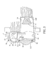
Figure 3 is a cross-sectional schematic view of the preferred embodiment. - Referring to
Figure 1 to Figure 3 , a preferred embodiment of the vehicle lamp of the present invention is exemplified as a near projecting lamp. - The vehicle lamp includes a lamp housing 1, a first
light emitting component 2 received in the lamp housing 1, asecond emitting component 6 received in the lamp housing 1, alens member 3 closing the lamp housing 1, a light-blockingplate 4 received in the lamp housing 1, areflector plate 5 received in the lamp housing 1, and a light guide piece 7 that is received in the lamp housing 1 and that covers the secondlight emitting component 6. - The lamp housing 1 defines a
receiving space 11 having first and second space portions adjacent to each other, and is formed with a light-exit opening 12. The first space portion is above the second space portion in this embodiment. Thereceiving space 11 has ashallow recess part 13 serving as the first space portion and extending rearwardly from a portion of the light-exit opening 12, and adeep recess part 14 serving as the second space portion and extending rearwardly from a remaining portion of the light-exit opening 12. Each of theshallow recess part 13 and thedeep recess part 14 has arecess bottom recess bottom 130 of theshallow recess part 13 is disposed closer to the light-exit opening 12 compared to therecess bottom 140 of thedeep recess part 14. - Each of the first
light emitting component 2 and the secondlight emitting component 6 is disposed in a respective one of theshallow recess part 13 and thedeep recess part 14. In this embodiment, the firstlight emitting component 2 is disposed on therecess bottom 130 of theshallow recess part 13, and the secondlight emitting component 6 is disposed on therecess bottom 140 of thedeep recess part 14. Accordingly, the firstlight emitting component 2 is disposed above the secondlight emitting component 6, and the firstlight emitting component 2 is disposed closer to the light-exit opening 12 compared to the secondlight emitting component 6. In this embodiment, the first and secondlight emitting components - The
lens member 3 closes the light-exit opening 12 of the lamp housing 1. Thelens member 3 includes ametallic mounting frame 31 for mounting on the lamp housing 1 at the light-exit opening 12, afirst lens body 32 mounted on themounting frame 31 and aligned with the firstlight emitting component 2, asecond lens body 33 mounted on themounting frame 31 and aligned with the secondlight emitting component 6, and aplastic lens frame 34 for securing thesecond lens body 33 on themounting frame 31. Preferably themounting frame 31 of thelens member 3 has an external surface formed with a first reflectiveconcave surface portion 311 that surrounds thefirst lens body 32, and a second reflectiveconcave surface portion 312 that surrounds thesecond lens body 33. In this embodiment, thefirst lens body 32 is a concave-convex lens, and thesecond lens body 33 is a plano-convex lens. - The light-blocking
plate 4 is disposed in the receiving space 1, is aligned with a portion of thesecond lens body 33 that is adjacent to thefirst lens body 32, and is disposed to block a portion of light radiated by the secondlight emitting component 6 from reaching thesecond lens body 33. - Each of the first
light emitting component 2 and thefirst lens body 32 has an edge proximate to the light-blockingplate 4. Thereflector plate 5 is disposed in thereceiving space 11 proximate to the edge of the firstlight emitting component 2 and the edge of thefirst lens body 32, and extends in a direction from the firstlight emitting component 2 toward thefirst lens body 32. - In more detail, the light-blocking
plate 4 and thereflector plate 5 are mounted on themounting frame 31, and are disposed at a vicinity of a junction of theshallow recess part 13 and thedeep recess part 14. Thereflector plate 5 is disposed above the light-blockingplate 4. The light-blockingplate 4 has one edge touching thereflector plate 5, and an opposite edge substantially aligned with an optical axis of thesecond lens body 33. - Primarily, light beams emitted from the first
light emitting component 2 will be reflected by thereflector plate 5, refracted and focused by thefirst lens body 32, and reflected again by the first reflectiveconcave surface portion 311. On the other hand, light beams emitted from the secondlight emitting component 6 will be refracted first by the light guide piece 7. Subsequently, a portion of the refracted light beams will be blocked by the light-blockingplate 4. A remaining portion thereof which is not blocked will be refracted again and focused by thesecond lens body 33, and reflected by the second reflectiveconcave surface portion 312. - Therefore, by using two pairs of corresponding and matching light emitting components and lens bodies to cooperate with other optical elements in a special spatial arrangement, the vehicle lamp may provide a light output with darker and brighter regions and a discernible boundary region between the darker and brighter regions so as to comply with traffic regulations. Moreover, arrangement of structural components of the vehicle lamp is relative simple and does not require complicated and high-precision-processed components, such that the vehicle lamp may be developed and manufactured with relative ease to reduce manufacturing costs.
Claims (11)
- A vehicle lamp comprising:a lamp housing (1) that defines a receiving space (11) having first and second space portions adjacent to each other, and that is formed with a light-exit opening (12);a first light emitting component (2) and a second light emitting component (6) disposed in a respective one of the first and second space portions;a lens member (3) closing the light-exit opening (12) of the lamp housing (1), the lens member (3) including a first lens body (32) aligned with the first light emitting component (2), and a second lens body (33) aligned with the second light emitting component (6); anda light-blocking plate (4) disposed in the receiving space (11), aligned with a portion of the second lens body (33) that is adjacent to the first lens body (32), and disposed to block a portion of light radiated by the second light emitting component (6) from reaching the second lens body (33).
- The vehicle lamp as claimed in Claim 1, characterized in that one of the first and second light emitting components (2, 6) is disposed closer to the light-exit opening (12) compared to the other one of the first and second light emitting components (2, 6).
- The vehicle lamp as claimed in Claim 2, further characterized in that the first light emitting component (2) is disposed closer to the light-exit opening (12) compared to the second light emitting component (6), the first light emitting component (2) being disposed above the second light emitting component (6).
- The vehicle lamp as claimed in Claim 3, further characterized in that the receiving space (11) has a shallow recess part (13) serving as the first space portion and a deep recess part (14) serving as the second space portion, each of the shallow recess part (13) and the deep recess part (14) having a recess bottom (130, 140), the recess bottom (130) of the shallow recess part (13) being disposed closer to the light-exit opening (12) compared to the recess bottom (140) of the deep recess part (14), the first light emitting component (2) being disposed in the shallow recess part (13), the second light emitting component (6) being disposed in the deep recess part (14).
- The vehicle lamp as claimed in any one of Claims 1 to 4, characterized in that each of the first light emitting component (2) and the first lens body (32) has an edge proximate to the light-blocking plate (4), the vehicle lamp further characterized by a reflector plate (5) that is disposed in the receiving space (11) proximate to the edge of the first light emitting component (2) and the edge of the first lens body (32) and that extends in a direction from the first light emitting component (2) toward the first lens body (32).
- The vehicle lamp as claimed in Claim 5, further characterized in that the light-blocking plate (4) and the reflector plate (5) are disposed at a vicinity of a junction of the shallow recess part (13) and the deep recess part (14), the reflector plate (5) being disposed above the light-blocking plate (4).
- The vehicle lamp as claimed in any one of Claims 1 to 6, further characterized by a light guide piece (7) disposed in the receiving space (11) and covering the second light emitting component (6).
- The vehicle lamp as claimed in any one of Claims 1 to 7, characterized in that the first lens body (32) is a concave-convex lens, and the second lens body (33) is a plano-convex lens.
- The vehicle lamp as claimed in any one of Claims 1 to 8, characterized in that the lens member (3) further includes a mounting frame (31) for mounting on the lamp housing (1) at the light-exit opening (12), the first lens body (32) and the second lens body (33) being disposed on the mounting frame (31).
- The vehicle lamp as claimed in Claim 9, further characterized in that the lens member (3) further includes a lens frame (34) for securing the second lens body (33) on the mounting frame (31).
- The vehicle lamp as claimed in Claim 9 or Claim 10, further characterized in that the mounting frame (31) of the lens member (3) has an external surface formed with a first reflective concave surface portion (311) that surrounds the first lens body (32), and a second reflective concave surface portion (312) that surrounds the second lens body (33).
Applications Claiming Priority (1)
| Application Number | Priority Date | Filing Date | Title |
|---|---|---|---|
| TW099222999U TWM405382U (en) | 2010-11-26 | 2010-11-26 | vehicle lamp |
Publications (1)
| Publication Number | Publication Date |
|---|---|
| EP2457769A1 true EP2457769A1 (en) | 2012-05-30 |
Family
ID=45079210
Family Applications (1)
| Application Number | Title | Priority Date | Filing Date |
|---|---|---|---|
| EP11155618A Withdrawn EP2457769A1 (en) | 2010-11-26 | 2011-02-23 | Vehicle lamp |
Country Status (3)
| Country | Link |
|---|---|
| US (1) | US20120134167A1 (en) |
| EP (1) | EP2457769A1 (en) |
| TW (1) | TWM405382U (en) |
Cited By (2)
| Publication number | Priority date | Publication date | Assignee | Title |
|---|---|---|---|---|
| WO2016001098A1 (en) * | 2014-06-30 | 2016-01-07 | Hella Kgaa Hueck & Co. | Projection lighting device for vehicles |
| EP3378745A1 (en) * | 2017-03-15 | 2018-09-26 | Honda Motor Co., Ltd. | Headlight structure of saddled vehicle |
Families Citing this family (16)
| Publication number | Priority date | Publication date | Assignee | Title |
|---|---|---|---|---|
| FR2993632B1 (en) * | 2012-07-19 | 2018-07-13 | Valeo Vision Belgique | DEVICE FOR TRANSMITTING A LIGHT BEAM AND PROJECTOR, IN PARTICULAR A MOTOR VEHICLE, COMPRISING SAID DEVICE |
| JP5948174B2 (en) * | 2012-07-23 | 2016-07-06 | 株式会社小糸製作所 | Railway vehicle lamp |
| US9464777B2 (en) * | 2013-03-15 | 2016-10-11 | Red Hawk LLC | LED light assemblies |
| JP6048749B2 (en) * | 2013-04-24 | 2016-12-21 | 本田技研工業株式会社 | Vehicle lighting system |
| CN105090852B (en) * | 2014-05-09 | 2018-10-16 | 松下知识产权经营株式会社 | Lighting device and automobile equipped with lighting device |
| JP6319725B2 (en) * | 2014-05-09 | 2018-05-09 | パナソニックIpマネジメント株式会社 | LIGHTING DEVICE AND AUTOMOBILE WITH LIGHTING DEVICE |
| JP6340687B2 (en) * | 2014-05-09 | 2018-06-13 | パナソニックIpマネジメント株式会社 | LIGHTING DEVICE AND AUTOMOBILE WITH LIGHTING DEVICE |
| KR102234377B1 (en) | 2014-07-31 | 2021-03-31 | 엘지이노텍 주식회사 | Lamp for vehicle |
| KR102234378B1 (en) * | 2014-07-31 | 2021-03-31 | 엘지이노텍 주식회사 | Lamp for vehicle |
| JP6340696B2 (en) * | 2014-08-29 | 2018-06-13 | パナソニックIpマネジメント株式会社 | Lighting device and automobile |
| FR3026462B1 (en) * | 2014-09-30 | 2019-06-28 | Valeo Vision Belgique | VEHICLE LIGHT DEVICE WITH PLATE OPTICAL ELEMENT WITH LIGHT SOURCE SUPPORT |
| JP2016219210A (en) * | 2015-05-19 | 2016-12-22 | パナソニックIpマネジメント株式会社 | Illuminating device and automobile including illuminating device |
| JP2017103189A (en) * | 2015-12-04 | 2017-06-08 | パナソニックIpマネジメント株式会社 | Headlamps and moving objects |
| CN109373281A (en) * | 2018-11-13 | 2019-02-22 | 深圳智诺车灯科技有限公司 | A LED car low beam headlamp |
| CN113757614B (en) * | 2020-06-02 | 2024-06-04 | 桦薪光电有限公司 | Lighting device for vehicle |
| TWD213854S (en) | 2020-07-27 | 2021-09-11 | 誠益光電科技股份有限公司 | Part of the lens |
Citations (7)
| Publication number | Priority date | Publication date | Assignee | Title |
|---|---|---|---|---|
| US5070432A (en) * | 1990-06-19 | 1991-12-03 | Koito Manufacturing Co., Ltd. | Projector-type automobile headlamp having improved appearance |
| US20060239022A1 (en) * | 2005-04-21 | 2006-10-26 | Koito Manufacturing Co., Ltd. | Projector-type lamp unit for vehicle |
| US20070086202A1 (en) * | 2005-10-13 | 2007-04-19 | Koito Manufacturing Co., Ltd. | Lamp unit of vehicle headlamp |
| US20080062709A1 (en) * | 2006-09-13 | 2008-03-13 | Koito Manufacturing Co., Ltd. | Vehicular lamp |
| US20090290372A1 (en) * | 2008-05-26 | 2009-11-26 | Koito Manufacturing Co., Ltd. | Vehicle headlamp |
| EP2187115A2 (en) * | 2008-11-12 | 2010-05-19 | Koito Manufacturing Co., Ltd. | Vehicular lamp |
| US20100226142A1 (en) * | 2009-02-12 | 2010-09-09 | Matthias Brendle | Projection Module for a Motor Vehicle Headlight |
-
2010
- 2010-11-26 TW TW099222999U patent/TWM405382U/en not_active IP Right Cessation
-
2011
- 2011-02-17 US US13/029,542 patent/US20120134167A1/en not_active Abandoned
- 2011-02-23 EP EP11155618A patent/EP2457769A1/en not_active Withdrawn
Patent Citations (7)
| Publication number | Priority date | Publication date | Assignee | Title |
|---|---|---|---|---|
| US5070432A (en) * | 1990-06-19 | 1991-12-03 | Koito Manufacturing Co., Ltd. | Projector-type automobile headlamp having improved appearance |
| US20060239022A1 (en) * | 2005-04-21 | 2006-10-26 | Koito Manufacturing Co., Ltd. | Projector-type lamp unit for vehicle |
| US20070086202A1 (en) * | 2005-10-13 | 2007-04-19 | Koito Manufacturing Co., Ltd. | Lamp unit of vehicle headlamp |
| US20080062709A1 (en) * | 2006-09-13 | 2008-03-13 | Koito Manufacturing Co., Ltd. | Vehicular lamp |
| US20090290372A1 (en) * | 2008-05-26 | 2009-11-26 | Koito Manufacturing Co., Ltd. | Vehicle headlamp |
| EP2187115A2 (en) * | 2008-11-12 | 2010-05-19 | Koito Manufacturing Co., Ltd. | Vehicular lamp |
| US20100226142A1 (en) * | 2009-02-12 | 2010-09-09 | Matthias Brendle | Projection Module for a Motor Vehicle Headlight |
Cited By (2)
| Publication number | Priority date | Publication date | Assignee | Title |
|---|---|---|---|---|
| WO2016001098A1 (en) * | 2014-06-30 | 2016-01-07 | Hella Kgaa Hueck & Co. | Projection lighting device for vehicles |
| EP3378745A1 (en) * | 2017-03-15 | 2018-09-26 | Honda Motor Co., Ltd. | Headlight structure of saddled vehicle |
Also Published As
| Publication number | Publication date |
|---|---|
| US20120134167A1 (en) | 2012-05-31 |
| TWM405382U (en) | 2011-06-11 |
Similar Documents
| Publication | Publication Date | Title |
|---|---|---|
| EP2457769A1 (en) | Vehicle lamp | |
| EP2525141B1 (en) | Vehicle headlamp | |
| US9587795B2 (en) | Headlight for in-vehicle use | |
| US9494290B2 (en) | Vehicle lamp | |
| EP2557357B1 (en) | Vehicle lighting device | |
| EP2019257A1 (en) | Vehicle lighting assembly and light guiding lens for use n vehicle lighting assembly | |
| JP2013222553A (en) | Lamp fitting for vehicle | |
| JP2016149274A (en) | Vehicle lighting | |
| CN109386807B (en) | Vehicle lamp | |
| EP2075500A2 (en) | Vehicle headlamp | |
| RU2613197C2 (en) | Vehicle lighting unit | |
| JP6241601B2 (en) | Lighting device | |
| JP2014175102A (en) | Lamp fitting for vehicle | |
| JP2026002974A (en) | lighting equipment | |
| CN105143756A (en) | Vehicle light | |
| CN108375038A (en) | Automotive lamp and motor vehicle | |
| JP2012089317A (en) | Lamp unit | |
| JP6205641B2 (en) | Vehicle lighting | |
| KR20150070551A (en) | A head lamp for vehicle | |
| JP6054724B2 (en) | Vehicle signal lights | |
| CN108351082A (en) | Method for manufacturing the design equipment for being used for vehicle and lighting device | |
| US20150098236A1 (en) | Optical structure for headlight | |
| KR102118140B1 (en) | Lamp for vehicle | |
| CN112443813B (en) | Vehicle marker light | |
| US20170219177A1 (en) | Optical element, optical module, and lens carrier |
Legal Events
| Date | Code | Title | Description |
|---|---|---|---|
| PUAI | Public reference made under article 153(3) epc to a published international application that has entered the european phase |
Free format text: ORIGINAL CODE: 0009012 |
|
| AK | Designated contracting states |
Kind code of ref document: A1 Designated state(s): AL AT BE BG CH CY CZ DE DK EE ES FI FR GB GR HR HU IE IS IT LI LT LU LV MC MK MT NL NO PL PT RO RS SE SI SK SM TR |
|
| AX | Request for extension of the european patent |
Extension state: BA ME |
|
| STAA | Information on the status of an ep patent application or granted ep patent |
Free format text: STATUS: THE APPLICATION IS DEEMED TO BE WITHDRAWN |
|
| 18D | Application deemed to be withdrawn |
Effective date: 20121201 |