EP2457707B1 - Device for regulating deformations of the bed of a geometrically aerodynamic mold and molding method with this device - Google Patents
Device for regulating deformations of the bed of a geometrically aerodynamic mold and molding method with this device Download PDFInfo
- Publication number
- EP2457707B1 EP2457707B1 EP11009446.3A EP11009446A EP2457707B1 EP 2457707 B1 EP2457707 B1 EP 2457707B1 EP 11009446 A EP11009446 A EP 11009446A EP 2457707 B1 EP2457707 B1 EP 2457707B1
- Authority
- EP
- European Patent Office
- Prior art keywords
- bed
- mold
- deformations
- rib
- regulating
- Prior art date
- Legal status (The legal status is an assumption and is not a legal conclusion. Google has not performed a legal analysis and makes no representation as to the accuracy of the status listed.)
- Active
Links
- 230000001105 regulatory effect Effects 0.000 title claims description 23
- 238000000034 method Methods 0.000 title claims description 13
- 238000000465 moulding Methods 0.000 title claims description 7
- 238000003475 lamination Methods 0.000 claims description 4
- 238000010030 laminating Methods 0.000 claims description 3
- 238000012986 modification Methods 0.000 claims description 3
- 230000004048 modification Effects 0.000 claims description 3
- 238000011417 postcuring Methods 0.000 claims description 3
- 238000003780 insertion Methods 0.000 claims description 2
- 230000037431 insertion Effects 0.000 claims description 2
- 230000033001 locomotion Effects 0.000 claims description 2
- 238000012546 transfer Methods 0.000 claims description 2
- 239000007769 metal material Substances 0.000 claims 1
- 239000002131 composite material Substances 0.000 description 11
- 238000004519 manufacturing process Methods 0.000 description 8
- 239000000463 material Substances 0.000 description 5
- 238000012937 correction Methods 0.000 description 4
- 238000010586 diagram Methods 0.000 description 3
- 230000000694 effects Effects 0.000 description 3
- 230000008602 contraction Effects 0.000 description 2
- 239000000835 fiber Substances 0.000 description 2
- 239000012467 final product Substances 0.000 description 2
- 239000000047 product Substances 0.000 description 2
- 239000011347 resin Substances 0.000 description 2
- 229920005989 resin Polymers 0.000 description 2
- 239000000853 adhesive Substances 0.000 description 1
- 230000001070 adhesive effect Effects 0.000 description 1
- 229910052782 aluminium Inorganic materials 0.000 description 1
- XAGFODPZIPBFFR-UHFFFAOYSA-N aluminium Chemical compound [Al] XAGFODPZIPBFFR-UHFFFAOYSA-N 0.000 description 1
- 238000007796 conventional method Methods 0.000 description 1
- 230000001419 dependent effect Effects 0.000 description 1
- 238000009826 distribution Methods 0.000 description 1
- 239000004744 fabric Substances 0.000 description 1
- 239000011152 fibreglass Substances 0.000 description 1
- 238000010348 incorporation Methods 0.000 description 1
- 238000001802 infusion Methods 0.000 description 1
- 238000005259 measurement Methods 0.000 description 1
- 229910052751 metal Inorganic materials 0.000 description 1
- 239000002184 metal Substances 0.000 description 1
- 238000006116 polymerization reaction Methods 0.000 description 1
- 238000011084 recovery Methods 0.000 description 1
- 238000009877 rendering Methods 0.000 description 1
- 230000000284 resting effect Effects 0.000 description 1
- 239000000126 substance Substances 0.000 description 1
- 238000009966 trimming Methods 0.000 description 1
- 230000003313 weakening effect Effects 0.000 description 1
Images


Classifications
-
- B—PERFORMING OPERATIONS; TRANSPORTING
- B29—WORKING OF PLASTICS; WORKING OF SUBSTANCES IN A PLASTIC STATE IN GENERAL
- B29C—SHAPING OR JOINING OF PLASTICS; SHAPING OF MATERIAL IN A PLASTIC STATE, NOT OTHERWISE PROVIDED FOR; AFTER-TREATMENT OF THE SHAPED PRODUCTS, e.g. REPAIRING
- B29C33/00—Moulds or cores; Details thereof or accessories therefor
- B29C33/30—Mounting, exchanging or centering
- B29C33/308—Adjustable moulds
-
- B—PERFORMING OPERATIONS; TRANSPORTING
- B29—WORKING OF PLASTICS; WORKING OF SUBSTANCES IN A PLASTIC STATE IN GENERAL
- B29C—SHAPING OR JOINING OF PLASTICS; SHAPING OF MATERIAL IN A PLASTIC STATE, NOT OTHERWISE PROVIDED FOR; AFTER-TREATMENT OF THE SHAPED PRODUCTS, e.g. REPAIRING
- B29C33/00—Moulds or cores; Details thereof or accessories therefor
-
- B—PERFORMING OPERATIONS; TRANSPORTING
- B29—WORKING OF PLASTICS; WORKING OF SUBSTANCES IN A PLASTIC STATE IN GENERAL
- B29C—SHAPING OR JOINING OF PLASTICS; SHAPING OF MATERIAL IN A PLASTIC STATE, NOT OTHERWISE PROVIDED FOR; AFTER-TREATMENT OF THE SHAPED PRODUCTS, e.g. REPAIRING
- B29C33/00—Moulds or cores; Details thereof or accessories therefor
- B29C33/0011—Moulds or cores; Details thereof or accessories therefor thin-walled moulds
-
- B—PERFORMING OPERATIONS; TRANSPORTING
- B29—WORKING OF PLASTICS; WORKING OF SUBSTANCES IN A PLASTIC STATE IN GENERAL
- B29C—SHAPING OR JOINING OF PLASTICS; SHAPING OF MATERIAL IN A PLASTIC STATE, NOT OTHERWISE PROVIDED FOR; AFTER-TREATMENT OF THE SHAPED PRODUCTS, e.g. REPAIRING
- B29C33/00—Moulds or cores; Details thereof or accessories therefor
- B29C33/30—Mounting, exchanging or centering
-
- B—PERFORMING OPERATIONS; TRANSPORTING
- B29—WORKING OF PLASTICS; WORKING OF SUBSTANCES IN A PLASTIC STATE IN GENERAL
- B29L—INDEXING SCHEME ASSOCIATED WITH SUBCLASS B29C, RELATING TO PARTICULAR ARTICLES
- B29L2031/00—Other particular articles
- B29L2031/08—Blades for rotors, stators, fans, turbines or the like, e.g. screw propellers
- B29L2031/082—Blades, e.g. for helicopters
- B29L2031/085—Wind turbine blades
-
- Y—GENERAL TAGGING OF NEW TECHNOLOGICAL DEVELOPMENTS; GENERAL TAGGING OF CROSS-SECTIONAL TECHNOLOGIES SPANNING OVER SEVERAL SECTIONS OF THE IPC; TECHNICAL SUBJECTS COVERED BY FORMER USPC CROSS-REFERENCE ART COLLECTIONS [XRACs] AND DIGESTS
- Y02—TECHNOLOGIES OR APPLICATIONS FOR MITIGATION OR ADAPTATION AGAINST CLIMATE CHANGE
- Y02P—CLIMATE CHANGE MITIGATION TECHNOLOGIES IN THE PRODUCTION OR PROCESSING OF GOODS
- Y02P70/00—Climate change mitigation technologies in the production process for final industrial or consumer products
- Y02P70/50—Manufacturing or production processes characterised by the final manufactured product
Definitions
- the present invention is related with the production of composite material pieces made with molds also of composite materials and, in particular, with a regulating device that allows correction of deformations that occur following a curing cycle in the bed of a mold made of composite material, minimizing profile errors of the product obtained from the mold.
- the invention is related with the method of molding pieces with the regulating device of the invention.
- the material undergoes a pre-curing and a final post-curing, both constituting a high temperature thermal cycle permitting the polymerization of the resin and thus attaining the mechanical properties required in the mold.
- US2003/0091679 A1 held by the same applicant of the present invention is known to address this issue and describes the production of a mold of wind turbine blade shells comprising two parts, upper and lower, joined together by a pivoting mechanism that permits attainment of all positions necessary to manufacture a blade.
- Each part of the mold, semi-mold comprises a bed or cradle of composite material resting on a structure braced against some ribs distributed along the bed.
- the bed is the part that gives the final product its aerodynamic geometry, likewise serving as a base for its production.
- this bed is formed by a sandwich structure with skins of composite material (preimpregnated) and an aluminum honeycomb core that acts as a thermal chamber by the introduction of hot air through some conduits situated along the bed.
- the conduits are coupled to the surface of the bed by some ribs that, by some runners secured to a pivoting system and some hinges on the legs of the mold structure, are designed to absorb the deviations of the mold.
- the present invention is related with a regulating device that adapts to the aerodynamic profile of a composite material mold bed that offsets the geometrical deviations originating therein.
- An object of the invention is to integrate the regulating device and the stiffening ribs of the composite material mold into a single element.
- Another object of the invention lies in having each regulating device act on the crosswise rigidity of the rib so as to transmit loads by the rib curving the section of the mold bed according to a defined strategy.
- each regulating device comprises various manually activated application points, and the number of application points shall increase as the width of the mold increases, consequently permitting coverage spanning the entire surface of the transverse section of the mold bed.
- Another object of the invention is that the ribs determine some openings for integrating the application points, which apply forces tangentially to the surface of the bed and modify the curvature of the rib itself and, consequently, the curvature of the section of the mold bed.
- Another object of the invention is to have the ribs under this invention acting as hinges on the mold bed.
- Another object of the invention is a method that, for the layout of the stiffening ribs, factors in not only the stability of the bed itself, but also the extent of actuation of the rib regulating system with a view to reducing the overall number of actuators per mold section.
- Another object of the invention is a molding method for a piece in which the ribs act as a rigid and permanent structural element after having corrected the deformations in the mold bed and secured the regulating system.
- Each semi-mold comprises a bed (1) made of composite material and is set on a structure braced (3) to some ribs (2) distributed along the bed (1).
- the ribs (2) lend transversal rigidity to the bed (1), rendering it geometrically stable and allowing the introduction of conduits (not represented) inside the mold, through which air introduced into the bed (1) circulates along the aerodynamic profile of the blade.
- Figure 1 shows a conventional stiffening rib (2) that follows the geometry of the composite material bed (1) of a semi-mold and is joined to it by an adhesive union and humid lamination.
- Metal framework (3) is supported on this conventional rib (2) and joined by some slides (4).
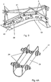
- the present invention comprises a regulating system that determines the distribution of a series of metallic ribs (20) along and fully supported on the surface of the bed of the semi-mold where these are laminated or adhered, and integrate some actuators (21), which permits correction or minimization of geometrical deviations originating in the bed (10) of the semi-mold (see figure 5 ).
- Each rib (20) comprises various actuators (21) that are manually activated and integrated in some divisions of the ribs (20) allowing profile modification of the bed (10) of the semi-mold by a change in curvature (see figure 3 ).
- the number of actuation elements (21) intended for incorporation shall be contingent on the aerodynamic profile of the mold. In other words, as the mold becomes wider, a greater the number of actuators (21) should be fitted.
- each actuator (21) generates a force (F) among the various parts of the ribs (20) into which it is integrated.
- This applied force (F) is appropriate in a moment (M) at the point where the rib (20) joins the bed (10).
- the actuator (21) generates a curvature (c) in the bed (10) that is proportional to the moment (M) applied.
- the trimming (22) made in the rib (20) follows a curvature that permits the control of the curvature of the rib (20) and the weakening controlled in the section of the ribs (20) act as hinges.
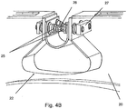
- the actuator (21), as shown in figures 4A and 4B , is a tensor type and is formed by a U-shaped connection (23) which transmits stresses between the cut-out points (22) on the rib (20).
- the actuator (21) has two bolts (24) with threaded actuation to the right and left for enhanced control over the curvature (c) of the rib (20), inserted in some orifices made in the cut-out points (22) of the rib (20) and secured using external locking elements (27) as well as washers to permit inclination of the walls of the rib (20).
- Each of the bolts (24) have some locking nuts (25) and a actuation point (26) to separate the external locking elements (27) to a desired distance depending on the insertion of the actuation bolt (24).
- the invention likewise comprises a molding method with a regulating device in accordance with the invention consisting of the following steps:
Landscapes
- Engineering & Computer Science (AREA)
- Mechanical Engineering (AREA)
- Moulding By Coating Moulds (AREA)
- Moulds For Moulding Plastics Or The Like (AREA)
- Wind Motors (AREA)
Description
- The present invention is related with the production of composite material pieces made with molds also of composite materials and, in particular, with a regulating device that allows correction of deformations that occur following a curing cycle in the bed of a mold made of composite material, minimizing profile errors of the product obtained from the mold. Likewise, the invention is related with the method of molding pieces with the regulating device of the invention.
- During manufacturing of a mold made of composite material, the material undergoes a pre-curing and a final post-curing, both constituting a high temperature thermal cycle permitting the polymerization of the resin and thus attaining the mechanical properties required in the mold.
- Later, during production of pieces made of composite material with this mold, it is common to undergo phenomena derived from expansion and contraction of the material, namely Spring-back (recovery of material elasticity) and Chemical Shrinkage (increase of the density of the material during the curing process).
- These effects provoked by thermal cycles result in permanent geometrical deformations in the bed of the molds that will later be transmitted to the products made in the mold.
- These effects intensify as the surface and geometrical complexity of the molds increase (double curvature and sharp angles).
The lack of repetitiveness in the behavior of pieces of large dimensions makes the correction of these deformations using a geometric factor applicable to the geometry of the model for which the mold is obtained unfeasible. Thus, these effects need to be mitigated by other means, whose objective is to keep the model of the mold from altering the geometry of the manufactured piece on the mold itself.
Some of these solutions are based on laminating the bed of the mold using a lamination made of fiberglass fabrics interwoven and preimpregnated with a low content of resin and following a balanced lamination sequence (in % of fiber) and symmetrical in the orientation of the fibers. Likewise, in order to reduce these deformations, the molds are manufactured on models having the same or similar coefficient of thermal expansion (CTE). Notwithstanding the above, these solutions failed to eradicate all the cited deviations. - In this respect,
US2003/0091679 A1 held by the same applicant of the present invention, is known to address this issue and describes the production of a mold of wind turbine blade shells comprising two parts, upper and lower, joined together by a pivoting mechanism that permits attainment of all positions necessary to manufacture a blade. Each part of the mold, semi-mold, comprises a bed or cradle of composite material resting on a structure braced against some ribs distributed along the bed. The bed is the part that gives the final product its aerodynamic geometry, likewise serving as a base for its production. In the cited Patent, this bed is formed by a sandwich structure with skins of composite material (preimpregnated) and an aluminum honeycomb core that acts as a thermal chamber by the introduction of hot air through some conduits situated along the bed.
The conduits are coupled to the surface of the bed by some ribs that, by some runners secured to a pivoting system and some hinges on the legs of the mold structure, are designed to absorb the deviations of the mold.
However, once the aforementioned deformations have occurred in the bed, they cannot be corrected with the ribs mentioned in the patent and the deformations could end up exceeding the mold bed's required surface tolerances and hence the final product obtained.
Other solutions in the State of the art are known to attempt to solve the deformations in the mold bed, particularly international patent applicationWO2010103493 , which describes a mold solution incorporating a longitudinally-laminated tube together with some actuators fitted in various sections perpendicular to the mold surface. These sections are in turn reinforced by a rib that joins the different actuators in a single section. Nonetheless, this solution obtains an elevated longitudinal rigidity and little cross rigidity, thus the adjustment or correction of the mold section is carried out lengthwise. On the other hand, this solution is not equipped with an expansion system and therefore not only fails to solve the aforementioned problems but also applies solely to low-temperature molds for infusion mold blades. - The present invention is related with a regulating device that adapts to the aerodynamic profile of a composite material mold bed that offsets the geometrical deviations originating therein.
- An object of the invention is to integrate the regulating device and the stiffening ribs of the composite material mold into a single element.
- Another object of the invention lies in having each regulating device act on the crosswise rigidity of the rib so as to transmit loads by the rib curving the section of the mold bed according to a defined strategy.
- Another object of the invention is that each regulating device comprises various manually activated application points, and the number of application points shall increase as the width of the mold increases, consequently permitting coverage spanning the entire surface of the transverse section of the mold bed.
- Another object of the invention is that the ribs determine some openings for integrating the application points, which apply forces tangentially to the surface of the bed and modify the curvature of the rib itself and, consequently, the curvature of the section of the mold bed.
- Another object of the invention is to have the ribs under this invention acting as hinges on the mold bed.
- Another object of the invention is a method that, for the layout of the stiffening ribs, factors in not only the stability of the bed itself, but also the extent of actuation of the rib regulating system with a view to reducing the overall number of actuators per mold section.
- Another object of the invention is a molding method for a piece in which the ribs act as a rigid and permanent structural element after having corrected the deformations in the mold bed and secured the regulating system.
- The invention provides a device in accordance with independent claim 1 and a method in accordance with independent claim 9. Further embodiments are defined in the dependent claims. These and other aspects of the invention shall be described in further detail with the aid of the drawings, which are described below.
-
-
Figure 1 shows a cross section diagram of a shell mold equipped with a conventional rib. -
Figure 2 is a diagram drawing of a rib fitted with a regulating system as per the invention. -
Figure 3 shows a diagram view of the regulating system according to the invention. -
Figures 4A and4B show perspective views of the regulating system actuator according to the invention. -
Figure 5 shows a perspective view of the rib placement process according to the invention. - Production of wind turbine blades utilizes shell molds formed by two semi-molds, upper and lower, joined together by a pivoting mechanism that makes any necessary position in blade production possible. Each semi-mold comprises a bed (1) made of composite material and is set on a structure braced (3) to some ribs (2) distributed along the bed (1). The ribs (2) lend transversal rigidity to the bed (1), rendering it geometrically stable and allowing the introduction of conduits (not represented) inside the mold, through which air introduced into the bed (1) circulates along the aerodynamic profile of the blade.
-
Figure 1 shows a conventional stiffening rib (2) that follows the geometry of the composite material bed (1) of a semi-mold and is joined to it by an adhesive union and humid lamination. Metal framework (3) is supported on this conventional rib (2) and joined by some slides (4). - However, the rigidity provided by conventional stiffening ribs (2) does not suffice to prevent geometrical deformations that, due to the phenomena derived from expansion and contraction of the materials, appear in the bed (1) of the mold and consequently transfer to the blade produced on the bed (1).
- The present invention comprises a regulating system that determines the distribution of a series of metallic ribs (20) along and fully supported on the surface of the bed of the semi-mold where these are laminated or adhered, and integrate some actuators (21), which permits correction or minimization of geometrical deviations originating in the bed (10) of the semi-mold (see
figure 5 ). - Each rib (20) comprises various actuators (21) that are manually activated and integrated in some divisions of the ribs (20) allowing profile modification of the bed (10) of the semi-mold by a change in curvature (see
figure 3 ). - To do so, the number of actuation elements (21) intended for incorporation shall be contingent on the aerodynamic profile of the mold. In other words, as the mold becomes wider, a greater the number of actuators (21) should be fitted.
- As shown in
figure 2 , each actuator (21) generates a force (F) among the various parts of the ribs (20) into which it is integrated. This applied force (F) is appropriate in a moment (M) at the point where the rib (20) joins the bed (10). The actuator (21) generates a curvature (c) in the bed (10) that is proportional to the moment (M) applied.
In order to have variation of the curvature (c) remain gradual and to keep it from being reflected in the bed (10) of the profile, the trimming (22) made in the rib (20) follows a curvature that permits the control of the curvature of the rib (20) and the weakening controlled in the section of the ribs (20) act as hinges.
The actuator (21), as shown infigures 4A and4B , is a tensor type and is formed by a U-shaped connection (23) which transmits stresses between the cut-out points (22) on the rib (20).
In the present embodiment, the actuator (21) has two bolts (24) with threaded actuation to the right and left for enhanced control over the curvature (c) of the rib (20), inserted in some orifices made in the cut-out points (22) of the rib (20) and secured using external locking elements (27) as well as washers to permit inclination of the walls of the rib (20). Each of the bolts (24) have some locking nuts (25) and a actuation point (26) to separate the external locking elements (27) to a desired distance depending on the insertion of the actuation bolt (24). - The invention likewise comprises a molding method with a regulating device in accordance with the invention consisting of the following steps:
- placing ribs (20) fitted with actuators (21) along the entire bed of the semi-mold perpendicular to the bed section (10) of the semi-mold with the actuators tensed, thus providing rigidity to the unit
- affixing or laminating the ribs on the bed of the mold and continuing the process of remanufacturing of the mold
- having concluded post-curing of the mold, measuring its surface to ascertain deviations on the bed (10)
- driving the actuators (21) on each rib (20), carrying out opening or closing motions to correct deformations or deviations detected in the bed (10)
- molding the blade itself
While the present invention has been described entirely in connection with the preferred embodiments, it is obvious that modifications can be made within this scope, as defined by the content of the following claims.
Claims (9)
- Device regulating deformations in the bed of an aerodynamically geometrical mold comprising two semi-molds and incorporating some stiffening ribs along the bed of each semi-mold, said stiffening ribs (20) secured on the surface of the bed (10) of a mold and each stiffening rib (20) integrates at least a single actuator (21),
said single actuator(20) permitting profile modification of the bed (10) of the mold, thus absorbing existing deviations in it derived from the curing process, characterized in that said each actuator (21) comprises a U-shaped connection (23) that transfers stresses among cut-out points (22) of the rib (20). - Device for regulating deformations in the bed according to claim 1, characterized in that each stiffening rib (20) is positioned perpendicular to the bed section (10) of the semi-mold and joined by adhesion or humid lamination to the surface of the semi-mold bed.
- Device for regulating deformations of the bed according to claim 1, characterized in that each stiffening rib (20) comprises at least a single manually activated actuator (21) in at least one cut-out point (22) at its structure.
- Device for regulating deformations of the bed, according to claim 1, characterized in that each actuator (21), when driven, generates a force (F) among the various integrated parts of the rib (20) appropriate in a moment (M) on the joint surface of the rib (20) to the bed (10) and generates a curvature (c) in the bed (10) proportional to the moment (M) applied.
- Device for regulating deformations according to claim 1, characterized in that the actuator (21) has two actuation bolts (24) with threading to the right and left for better control over the curvature (c) of the rib (20) and washers that permit the inclination of the walls of the rib (20).
- Device for regulating deformations of the bed, according to claim 5, characterized in that each actuation bolt (24) is inserted in some orifices made in the cut-out points (22) on the rib (20) and secured with some external locking elements (27).
- Device for regulating deformations of the bed of an aerodynamically geometrical mold, according to claim 6, characterized in that each bolt (24) is fitted with locking nuts (25) and a actuation point (26) for separating elements from an external locking element (27) to a desired distance depending on the relation of the insertion of the actuation bolt (24).
- Device for regulating deformations of the bed of an aerodynamically geometrical mold, according to claim 1, characterized in that the ribs (20) are made of a metal material.
- Molding method with a regulating device as described in claim 1, characterized in that it comprises steps of:- placing ribs (20) fitted with actuators (21) along the entire bed of the semi-mold perpendicular to the bed section (10) of the semi-mold with the actuators tensed, thus providing rigidity to the unit- affixing or laminating the ribs on the bed of the mold and continuing the process of remanufacturing of the mold- having concluded post-curing of the mold, measuring its surface to ascertain deviations on the bed (10)- driving the actuators (21) on each rib (20), carrying out opening or closing motions to correct deformations or deviations detected in the bed (10)- molding the blade itself
Applications Claiming Priority (1)
| Application Number | Priority Date | Filing Date | Title |
|---|---|---|---|
| ES201001526A ES2387857B1 (en) | 2010-11-30 | 2010-11-30 | DEVICE FOR REGULATION OF THE DEFINITIONS OF THE MILK OF AN AERODYNAMIC GEOMETRY MOLD AND MOLDING METHOD WITH SUCH DEVICE |
Publications (3)
| Publication Number | Publication Date |
|---|---|
| EP2457707A2 EP2457707A2 (en) | 2012-05-30 |
| EP2457707A3 EP2457707A3 (en) | 2017-08-16 |
| EP2457707B1 true EP2457707B1 (en) | 2018-10-17 |
Family
ID=45218177
Family Applications (1)
| Application Number | Title | Priority Date | Filing Date |
|---|---|---|---|
| EP11009446.3A Active EP2457707B1 (en) | 2010-11-30 | 2011-11-29 | Device for regulating deformations of the bed of a geometrically aerodynamic mold and molding method with this device |
Country Status (6)
| Country | Link |
|---|---|
| US (1) | US8961842B2 (en) |
| EP (1) | EP2457707B1 (en) |
| CN (1) | CN102555115B (en) |
| BR (1) | BRPI1107041B1 (en) |
| DK (1) | DK2457707T3 (en) |
| ES (2) | ES2387857B1 (en) |
Families Citing this family (8)
| Publication number | Priority date | Publication date | Assignee | Title |
|---|---|---|---|---|
| CN104010784B (en) * | 2011-10-19 | 2016-02-24 | 维斯塔斯风力系统有限公司 | Brackets for clamping wind turbine blade molds to support structures |
| US20130328241A1 (en) * | 2012-06-07 | 2013-12-12 | John M. Obrecht | Arrangement and method for manufacturing a wind turbine blade |
| DE202013105458U1 (en) * | 2013-11-29 | 2014-11-19 | Vestas Wind Systems A/S | Curing tool and components thereof for curing prepreg molds for wind turbine rotor blades in autoclaves |
| DE102017011737A1 (en) | 2017-12-19 | 2019-06-19 | EUROS - Entwicklungsgesellschaft für Windkraftanlagen mbH | Method and system for operating a wind turbine |
| BR112020025414B1 (en) | 2018-06-12 | 2023-05-09 | Tpi Composites, Inc. | APPLIANCE FOR ASSEMBLING WIND GENERATOR BLADE COMPONENTS |
| EP3715080A1 (en) | 2019-03-26 | 2020-09-30 | Siemens Gamesa Renewable Energy A/S | Modular molding device, molding system and method for creating a mold for a blade segment of a wind turbine blade of a wind turbine |
| US11813811B2 (en) * | 2019-05-22 | 2023-11-14 | The Boeing Company | Conformable apparatus, systems and methods for treating a composite material |
| US11801619B2 (en) * | 2021-10-05 | 2023-10-31 | The Boeing Company | Rapid tooling layup mandrel |
Family Cites Families (33)
| Publication number | Priority date | Publication date | Assignee | Title |
|---|---|---|---|---|
| US2227966A (en) * | 1938-04-21 | 1941-01-07 | Eastman Kodak Co | Injection type mold |
| US3587135A (en) * | 1969-06-11 | 1971-06-28 | Us Industries Inc | Compression molding machine |
| US3618886A (en) * | 1969-07-18 | 1971-11-09 | Phillip Graham | Adjustable panel form for thin shells |
| BE788803A (en) * | 1971-09-14 | 1973-01-02 | Meier Peter | IMPROVEMENT IN THE MANUFACTURING OF CONSTRUCTION ELEMENTS |
| FR2163897A5 (en) * | 1971-12-06 | 1973-07-27 | Coignet Edmond Const | |
| DE2807954C3 (en) * | 1978-02-24 | 1981-04-16 | Alfred 7750 Konstanz Fuchs | Device for making a curved sail |
| FR2565157B1 (en) * | 1984-06-01 | 1987-01-30 | Deficis Alain | MOLD FOR LOW PRESSURE MOLDING, METHOD FOR PRODUCING THE SAME, AND METHOD FOR MOLDING AN OBJECT |
| FR2569819B1 (en) * | 1984-08-31 | 1986-08-29 | Engineering Management Data Pr | TRANSFORMABLE MOLD AND MANUFACTURING METHOD THEREOF |
| JPH078505B2 (en) * | 1986-07-30 | 1995-02-01 | 株式会社イノアックコ−ポレ−ション | Method for producing plastic foam |
| EP0256490B1 (en) * | 1986-08-12 | 1992-04-29 | Toshiba Kikai Kabushiki Kaisha | Heat displacing type dies |
| US5151277A (en) * | 1991-03-27 | 1992-09-29 | The Charles Stark Draper Lab., Inc. | Reconfigurable fiber-forming resin transfer system |
| DE4116439C1 (en) * | 1991-05-18 | 1992-08-27 | Maier G Paschal Werk | |
| GB2268699B (en) * | 1992-07-16 | 1996-09-18 | British Aerospace | Forming fibre reinforced plastics laminates |
| US5372349A (en) * | 1993-04-27 | 1994-12-13 | Jte, Inc. | Single form system and method for molding pre-cast structural wall panels of different sizes for different types of wall systems |
| FR2711705B1 (en) * | 1993-10-27 | 1996-01-12 | Sateco Sa | Formwork device with adjustable radius of curvature, especially for concrete structures. |
| JP2996882B2 (en) * | 1994-10-20 | 2000-01-11 | 東芝機械株式会社 | Thermal displacement T-die |
| US6354561B1 (en) * | 1996-07-11 | 2002-03-12 | Otmar Fahrion | Adjustable casting mould, and device for adjusting the mould surface thereof |
| US6561118B2 (en) * | 2000-01-14 | 2003-05-13 | Kirby J. Mead | Flexible male/female mold for custom surfboard production |
| US6298896B1 (en) * | 2000-03-28 | 2001-10-09 | Northrop Grumman Corporation | Apparatus for constructing a composite structure |
| IT1320077B1 (en) * | 2000-10-25 | 2003-11-18 | Metecno Spa | MOLD FOR CURVED PANELS. |
| JP2003126923A (en) * | 2001-10-24 | 2003-05-08 | Honda Motor Co Ltd | Method of forming tubular member |
| ES2208028B1 (en) | 2001-11-12 | 2005-06-01 | Gamesa Desarrollos Aeronauticos, S.A. | SHELL MOLD FOR THE MANUFACTURE OF AIRLINER SHOES AND MOLD AS CONSTITUTED. |
| US6923635B2 (en) * | 2002-12-12 | 2005-08-02 | Vec Industries, L.L.C. | Adjustable frame support for pre formed mold |
| KR101054866B1 (en) * | 2003-02-13 | 2011-08-05 | 테크마이어 엘티디 | Die casting device |
| EP1600218B1 (en) * | 2003-03-03 | 2009-09-23 | Toray Industries, Inc. | Slit die, and method and device for producing base material with coating film |
| US7398586B2 (en) * | 2005-11-01 | 2008-07-15 | The Boeing Company | Methods and systems for manufacturing a family of aircraft wings and other composite structures |
| CN2865900Y (en) * | 2005-12-02 | 2007-02-07 | 中国重型汽车集团有限公司 | A U-type thick plate bending mold |
| US20080302500A1 (en) * | 2007-06-07 | 2008-12-11 | The Boeing Company | Reusable mold forming tool |
| ES2367490B1 (en) * | 2008-05-23 | 2012-09-17 | Aeroblade Sa | IMPROVEMENTS IN THE MOLDS FOR THE MANUFACTURE OF AIRLINES |
| ES2377369B1 (en) * | 2008-07-31 | 2013-02-05 | Manuel Torres Martínez | USEFUL FOR THE MANUFACTURE OF AERODINE AND AEROGENERATING COMPONENTS AND MANUFACTURING PROCESS OF THESE COMPONENTS. |
| CN201357528Y (en) * | 2009-03-13 | 2009-12-09 | 苏州红枫风电模具有限公司 | Wind turbine blade die |
| CN201456269U (en) * | 2009-07-17 | 2010-05-12 | 上海越科复合材料有限公司 | Microdeformation adjusting device for mould made of composite material |
| CN101837410A (en) * | 2010-06-30 | 2010-09-22 | 重庆理工大学 | Multipoint forming die based on solid particle medium back pressure |
-
2010
- 2010-11-30 ES ES201001526A patent/ES2387857B1/en not_active Expired - Fee Related
-
2011
- 2011-11-29 CN CN201110396811.4A patent/CN102555115B/en active Active
- 2011-11-29 ES ES11009446T patent/ES2696549T3/en active Active
- 2011-11-29 EP EP11009446.3A patent/EP2457707B1/en active Active
- 2011-11-29 DK DK11009446.3T patent/DK2457707T3/en active
- 2011-11-30 US US13/307,489 patent/US8961842B2/en active Active
- 2011-11-30 BR BRPI1107041-2A patent/BRPI1107041B1/en active IP Right Grant
Also Published As
| Publication number | Publication date |
|---|---|
| ES2696549T3 (en) | 2019-01-16 |
| US20120133066A1 (en) | 2012-05-31 |
| EP2457707A3 (en) | 2017-08-16 |
| EP2457707A2 (en) | 2012-05-30 |
| ES2387857B1 (en) | 2013-11-07 |
| BRPI1107041B1 (en) | 2020-10-20 |
| US8961842B2 (en) | 2015-02-24 |
| BRPI1107041A2 (en) | 2015-09-22 |
| CN102555115A (en) | 2012-07-11 |
| CN102555115B (en) | 2015-11-25 |
| DK2457707T3 (en) | 2019-01-07 |
| ES2387857A1 (en) | 2012-10-02 |
Similar Documents
| Publication | Publication Date | Title |
|---|---|---|
| US8961842B2 (en) | Device for regulating deformations of the bed of a geometrically aerodynamic mold and molding method with this device | |
| EP2109713B1 (en) | Wind turbine blade | |
| US11453183B2 (en) | Wind turbine blade manufacture | |
| EP2176058B1 (en) | A method of manufacturing an integral profile monolithic wing structure | |
| US20120087801A1 (en) | Composite components and processes therefor | |
| EP1316400B1 (en) | Shell mould assembly | |
| EP2418072B1 (en) | A method of manufacturing an elongated composite structure | |
| US11092132B2 (en) | Method of manufacturing a wind turbine blade | |
| US8424805B2 (en) | Airfoil structure | |
| EP3380313B1 (en) | Improvements relating to the manufacture of wind turbine blades | |
| EP3802090B1 (en) | A system and method for manufacturing a wind turbine blade | |
| US10690113B2 (en) | Wind turbine blades and related methods of manufacturing | |
| DK3019332T3 (en) | WIND TURBINE BLADE | |
| US12053939B2 (en) | Mould tool for manufacture of a wind turbine blade | |
| EP2731788B1 (en) | Masterless layup mandrel tool | |
| DK2716904T3 (en) | A method of manufacturing a composite beam head for a wind turbine rotor blade | |
| DK2379312T3 (en) | PROCEDURE FOR PREPARING A WINDMILL LEAVE AND PREFORM FOR USE IN A WINDMILL LEAVE |
Legal Events
| Date | Code | Title | Description |
|---|---|---|---|
| PUAI | Public reference made under article 153(3) epc to a published international application that has entered the european phase |
Free format text: ORIGINAL CODE: 0009012 |
|
| AK | Designated contracting states |
Kind code of ref document: A2 Designated state(s): AL AT BE BG CH CY CZ DE DK EE ES FI FR GB GR HR HU IE IS IT LI LT LU LV MC MK MT NL NO PL PT RO RS SE SI SK SM TR |
|
| AX | Request for extension of the european patent |
Extension state: BA ME |
|
| PUAL | Search report despatched |
Free format text: ORIGINAL CODE: 0009013 |
|
| AK | Designated contracting states |
Kind code of ref document: A3 Designated state(s): AL AT BE BG CH CY CZ DE DK EE ES FI FR GB GR HR HU IE IS IT LI LT LU LV MC MK MT NL NO PL PT RO RS SE SI SK SM TR |
|
| AX | Request for extension of the european patent |
Extension state: BA ME |
|
| RIC1 | Information provided on ipc code assigned before grant |
Ipc: B29C 33/30 20060101AFI20170713BHEP |
|
| 17P | Request for examination filed |
Effective date: 20180126 |
|
| RBV | Designated contracting states (corrected) |
Designated state(s): AL AT BE BG CH CY CZ DE DK EE ES FI FR GB GR HR HU IE IS IT LI LT LU LV MC MK MT NL NO PL PT RO RS SE SI SK SM TR |
|
| GRAP | Despatch of communication of intention to grant a patent |
Free format text: ORIGINAL CODE: EPIDOSNIGR1 |
|
| INTG | Intention to grant announced |
Effective date: 20180508 |
|
| GRAS | Grant fee paid |
Free format text: ORIGINAL CODE: EPIDOSNIGR3 |
|
| GRAA | (expected) grant |
Free format text: ORIGINAL CODE: 0009210 |
|
| AK | Designated contracting states |
Kind code of ref document: B1 Designated state(s): AL AT BE BG CH CY CZ DE DK EE ES FI FR GB GR HR HU IE IS IT LI LT LU LV MC MK MT NL NO PL PT RO RS SE SI SK SM TR |
|
| REG | Reference to a national code |
Ref country code: GB Ref legal event code: FG4D |
|
| REG | Reference to a national code |
Ref country code: CH Ref legal event code: EP |
|
| REG | Reference to a national code |
Ref country code: IE Ref legal event code: FG4D |
|
| REG | Reference to a national code |
Ref country code: DE Ref legal event code: R096 Ref document number: 602011052901 Country of ref document: DE Ref country code: AT Ref legal event code: REF Ref document number: 1053465 Country of ref document: AT Kind code of ref document: T Effective date: 20181115 |
|
| REG | Reference to a national code |
Ref country code: DK Ref legal event code: T3 Effective date: 20190103 |
|
| REG | Reference to a national code |
Ref country code: ES Ref legal event code: FG2A Ref document number: 2696549 Country of ref document: ES Kind code of ref document: T3 Effective date: 20190116 |
|
| REG | Reference to a national code |
Ref country code: NL Ref legal event code: MP Effective date: 20181017 |
|
| REG | Reference to a national code |
Ref country code: LT Ref legal event code: MG4D |
|
| REG | Reference to a national code |
Ref country code: AT Ref legal event code: MK05 Ref document number: 1053465 Country of ref document: AT Kind code of ref document: T Effective date: 20181017 |
|
| PG25 | Lapsed in a contracting state [announced via postgrant information from national office to epo] |
Ref country code: NL Free format text: LAPSE BECAUSE OF FAILURE TO SUBMIT A TRANSLATION OF THE DESCRIPTION OR TO PAY THE FEE WITHIN THE PRESCRIBED TIME-LIMIT Effective date: 20181017 |
|
| RAP2 | Party data changed (patent owner data changed or rights of a patent transferred) |
Owner name: SIEMENS GAMESA RENEWABLE ENERGY INNOVATION & TECHN |
|
| PG25 | Lapsed in a contracting state [announced via postgrant information from national office to epo] |
Ref country code: LT Free format text: LAPSE BECAUSE OF FAILURE TO SUBMIT A TRANSLATION OF THE DESCRIPTION OR TO PAY THE FEE WITHIN THE PRESCRIBED TIME-LIMIT Effective date: 20181017 Ref country code: NO Free format text: LAPSE BECAUSE OF FAILURE TO SUBMIT A TRANSLATION OF THE DESCRIPTION OR TO PAY THE FEE WITHIN THE PRESCRIBED TIME-LIMIT Effective date: 20190117 Ref country code: IS Free format text: LAPSE BECAUSE OF FAILURE TO SUBMIT A TRANSLATION OF THE DESCRIPTION OR TO PAY THE FEE WITHIN THE PRESCRIBED TIME-LIMIT Effective date: 20190217 Ref country code: AT Free format text: LAPSE BECAUSE OF FAILURE TO SUBMIT A TRANSLATION OF THE DESCRIPTION OR TO PAY THE FEE WITHIN THE PRESCRIBED TIME-LIMIT Effective date: 20181017 Ref country code: PL Free format text: LAPSE BECAUSE OF FAILURE TO SUBMIT A TRANSLATION OF THE DESCRIPTION OR TO PAY THE FEE WITHIN THE PRESCRIBED TIME-LIMIT Effective date: 20181017 Ref country code: HR Free format text: LAPSE BECAUSE OF FAILURE TO SUBMIT A TRANSLATION OF THE DESCRIPTION OR TO PAY THE FEE WITHIN THE PRESCRIBED TIME-LIMIT Effective date: 20181017 Ref country code: BG Free format text: LAPSE BECAUSE OF FAILURE TO SUBMIT A TRANSLATION OF THE DESCRIPTION OR TO PAY THE FEE WITHIN THE PRESCRIBED TIME-LIMIT Effective date: 20190117 Ref country code: FI Free format text: LAPSE BECAUSE OF FAILURE TO SUBMIT A TRANSLATION OF THE DESCRIPTION OR TO PAY THE FEE WITHIN THE PRESCRIBED TIME-LIMIT Effective date: 20181017 Ref country code: LV Free format text: LAPSE BECAUSE OF FAILURE TO SUBMIT A TRANSLATION OF THE DESCRIPTION OR TO PAY THE FEE WITHIN THE PRESCRIBED TIME-LIMIT Effective date: 20181017 |
|
| PG25 | Lapsed in a contracting state [announced via postgrant information from national office to epo] |
Ref country code: AL Free format text: LAPSE BECAUSE OF FAILURE TO SUBMIT A TRANSLATION OF THE DESCRIPTION OR TO PAY THE FEE WITHIN THE PRESCRIBED TIME-LIMIT Effective date: 20181017 Ref country code: SE Free format text: LAPSE BECAUSE OF FAILURE TO SUBMIT A TRANSLATION OF THE DESCRIPTION OR TO PAY THE FEE WITHIN THE PRESCRIBED TIME-LIMIT Effective date: 20181017 Ref country code: GR Free format text: LAPSE BECAUSE OF FAILURE TO SUBMIT A TRANSLATION OF THE DESCRIPTION OR TO PAY THE FEE WITHIN THE PRESCRIBED TIME-LIMIT Effective date: 20190118 Ref country code: RS Free format text: LAPSE BECAUSE OF FAILURE TO SUBMIT A TRANSLATION OF THE DESCRIPTION OR TO PAY THE FEE WITHIN THE PRESCRIBED TIME-LIMIT Effective date: 20181017 Ref country code: PT Free format text: LAPSE BECAUSE OF FAILURE TO SUBMIT A TRANSLATION OF THE DESCRIPTION OR TO PAY THE FEE WITHIN THE PRESCRIBED TIME-LIMIT Effective date: 20190217 |
|
| REG | Reference to a national code |
Ref country code: CH Ref legal event code: PL |
|
| REG | Reference to a national code |
Ref country code: DE Ref legal event code: R097 Ref document number: 602011052901 Country of ref document: DE |
|
| PG25 | Lapsed in a contracting state [announced via postgrant information from national office to epo] |
Ref country code: CZ Free format text: LAPSE BECAUSE OF FAILURE TO SUBMIT A TRANSLATION OF THE DESCRIPTION OR TO PAY THE FEE WITHIN THE PRESCRIBED TIME-LIMIT Effective date: 20181017 Ref country code: IT Free format text: LAPSE BECAUSE OF FAILURE TO SUBMIT A TRANSLATION OF THE DESCRIPTION OR TO PAY THE FEE WITHIN THE PRESCRIBED TIME-LIMIT Effective date: 20181017 Ref country code: LU Free format text: LAPSE BECAUSE OF NON-PAYMENT OF DUE FEES Effective date: 20181129 |
|
| REG | Reference to a national code |
Ref country code: BE Ref legal event code: MM Effective date: 20181130 |
|
| REG | Reference to a national code |
Ref country code: IE Ref legal event code: MM4A |
|
| PLBE | No opposition filed within time limit |
Free format text: ORIGINAL CODE: 0009261 |
|
| STAA | Information on the status of an ep patent application or granted ep patent |
Free format text: STATUS: NO OPPOSITION FILED WITHIN TIME LIMIT |
|
| PG25 | Lapsed in a contracting state [announced via postgrant information from national office to epo] |
Ref country code: CH Free format text: LAPSE BECAUSE OF NON-PAYMENT OF DUE FEES Effective date: 20181130 Ref country code: EE Free format text: LAPSE BECAUSE OF FAILURE TO SUBMIT A TRANSLATION OF THE DESCRIPTION OR TO PAY THE FEE WITHIN THE PRESCRIBED TIME-LIMIT Effective date: 20181017 Ref country code: SM Free format text: LAPSE BECAUSE OF FAILURE TO SUBMIT A TRANSLATION OF THE DESCRIPTION OR TO PAY THE FEE WITHIN THE PRESCRIBED TIME-LIMIT Effective date: 20181017 Ref country code: LI Free format text: LAPSE BECAUSE OF NON-PAYMENT OF DUE FEES Effective date: 20181130 Ref country code: RO Free format text: LAPSE BECAUSE OF FAILURE TO SUBMIT A TRANSLATION OF THE DESCRIPTION OR TO PAY THE FEE WITHIN THE PRESCRIBED TIME-LIMIT Effective date: 20181017 Ref country code: SK Free format text: LAPSE BECAUSE OF FAILURE TO SUBMIT A TRANSLATION OF THE DESCRIPTION OR TO PAY THE FEE WITHIN THE PRESCRIBED TIME-LIMIT Effective date: 20181017 Ref country code: MC Free format text: LAPSE BECAUSE OF FAILURE TO SUBMIT A TRANSLATION OF THE DESCRIPTION OR TO PAY THE FEE WITHIN THE PRESCRIBED TIME-LIMIT Effective date: 20181017 |
|
| 26N | No opposition filed |
Effective date: 20190718 |
|
| PG25 | Lapsed in a contracting state [announced via postgrant information from national office to epo] |
Ref country code: FR Free format text: LAPSE BECAUSE OF NON-PAYMENT OF DUE FEES Effective date: 20181217 Ref country code: IE Free format text: LAPSE BECAUSE OF NON-PAYMENT OF DUE FEES Effective date: 20181129 Ref country code: SI Free format text: LAPSE BECAUSE OF FAILURE TO SUBMIT A TRANSLATION OF THE DESCRIPTION OR TO PAY THE FEE WITHIN THE PRESCRIBED TIME-LIMIT Effective date: 20181017 |
|
| PG25 | Lapsed in a contracting state [announced via postgrant information from national office to epo] |
Ref country code: BE Free format text: LAPSE BECAUSE OF NON-PAYMENT OF DUE FEES Effective date: 20181130 |
|
| PG25 | Lapsed in a contracting state [announced via postgrant information from national office to epo] |
Ref country code: MT Free format text: LAPSE BECAUSE OF NON-PAYMENT OF DUE FEES Effective date: 20181129 |
|
| PG25 | Lapsed in a contracting state [announced via postgrant information from national office to epo] |
Ref country code: TR Free format text: LAPSE BECAUSE OF FAILURE TO SUBMIT A TRANSLATION OF THE DESCRIPTION OR TO PAY THE FEE WITHIN THE PRESCRIBED TIME-LIMIT Effective date: 20181017 |
|
| PG25 | Lapsed in a contracting state [announced via postgrant information from national office to epo] |
Ref country code: HU Free format text: LAPSE BECAUSE OF FAILURE TO SUBMIT A TRANSLATION OF THE DESCRIPTION OR TO PAY THE FEE WITHIN THE PRESCRIBED TIME-LIMIT; INVALID AB INITIO Effective date: 20111129 Ref country code: CY Free format text: LAPSE BECAUSE OF FAILURE TO SUBMIT A TRANSLATION OF THE DESCRIPTION OR TO PAY THE FEE WITHIN THE PRESCRIBED TIME-LIMIT Effective date: 20181017 Ref country code: MK Free format text: LAPSE BECAUSE OF NON-PAYMENT OF DUE FEES Effective date: 20181017 |
|
| REG | Reference to a national code |
Ref country code: DE Ref legal event code: R082 Ref document number: 602011052901 Country of ref document: DE Representative=s name: SAUTHOFF, KARSTEN, DIPL.-ING. UNIV., DE |
|
| PGFP | Annual fee paid to national office [announced via postgrant information from national office to epo] |
Ref country code: DE Payment date: 20241128 Year of fee payment: 14 |
|
| PGFP | Annual fee paid to national office [announced via postgrant information from national office to epo] |
Ref country code: DK Payment date: 20241126 Year of fee payment: 14 |
|
| PGFP | Annual fee paid to national office [announced via postgrant information from national office to epo] |
Ref country code: GB Payment date: 20241126 Year of fee payment: 14 |
|
| PGFP | Annual fee paid to national office [announced via postgrant information from national office to epo] |
Ref country code: ES Payment date: 20241218 Year of fee payment: 14 |