EP2457701A2 - Cutting machine - Google Patents
Cutting machine Download PDFInfo
- Publication number
- EP2457701A2 EP2457701A2 EP11187482A EP11187482A EP2457701A2 EP 2457701 A2 EP2457701 A2 EP 2457701A2 EP 11187482 A EP11187482 A EP 11187482A EP 11187482 A EP11187482 A EP 11187482A EP 2457701 A2 EP2457701 A2 EP 2457701A2
- Authority
- EP
- European Patent Office
- Prior art keywords
- receiving member
- insert receiving
- battery pack
- handle
- housing
- Prior art date
- Legal status (The legal status is an assumption and is not a legal conclusion. Google has not performed a legal analysis and makes no representation as to the accuracy of the status listed.)
- Granted
Links
- 238000009434 installation Methods 0.000 claims abstract description 9
- 239000000428 dust Substances 0.000 description 8
- 239000002245 particle Substances 0.000 description 8
- 239000000463 material Substances 0.000 description 3
- 238000009825 accumulation Methods 0.000 description 1
- 238000001816 cooling Methods 0.000 description 1
Images
Classifications
-
- B—PERFORMING OPERATIONS; TRANSPORTING
- B25—HAND TOOLS; PORTABLE POWER-DRIVEN TOOLS; MANIPULATORS
- B25F—COMBINATION OR MULTI-PURPOSE TOOLS NOT OTHERWISE PROVIDED FOR; DETAILS OR COMPONENTS OF PORTABLE POWER-DRIVEN TOOLS NOT PARTICULARLY RELATED TO THE OPERATIONS PERFORMED AND NOT OTHERWISE PROVIDED FOR
- B25F5/00—Details or components of portable power-driven tools not particularly related to the operations performed and not otherwise provided for
- B25F5/02—Construction of casings, bodies or handles
-
- B—PERFORMING OPERATIONS; TRANSPORTING
- B23—MACHINE TOOLS; METAL-WORKING NOT OTHERWISE PROVIDED FOR
- B23D—PLANING; SLOTTING; SHEARING; BROACHING; SAWING; FILING; SCRAPING; LIKE OPERATIONS FOR WORKING METAL BY REMOVING MATERIAL, NOT OTHERWISE PROVIDED FOR
- B23D51/00—Sawing machines or sawing devices working with straight blades, characterised only by constructional features of particular parts; Carrying or attaching means for tools, covered by this subclass, which are connected to a carrier at both ends
Definitions
- This invention relates to a cutting machine including a handle provided on top of a housing accommodating a motor, and a cutting blade operated by the motor driven by a battery pack.
- Japanese Laid-open Patent Application Publication No. 2008-173712 discloses a cutting machine which includes a battery pack for supplying power to a motor and/or the like.
- a rear end of a housing accommodating the motor is coupled to a handle, and the battery pack is slid onto the rear end of the handle for installation.
- the above-described cutting machine is required to fit the handle with the battery pack, the dimensions of the handle are increased in accordance with the battery pack, causing reduced usability of the cutting machine. Further, when the battery pack is slid, in particular, from above to bottom for installation, the battery pack may possibly not be easily installed because the battery pack is not readily slid onto the handle with stability.
- the present invention has been made in view of the above circumstances and provides a cutting machine that provides increased usability and is capable of facilitating installation of a battery pack.
- a first aspect of the present invention provides a cutting machine comprising a housing, a motor that is accommodated in the housing, a handle that is provided on top of housing, a cutting blade that is operated by the motor driven by a battery pack which is a power source, and an insert receiving member that is formed in the housing at the rear of the handle and has an open top end to allow the battery pack to be inserted into the insert receiving member through the open top end from above for installation.
- the insert receiving member is integrally joined to the handle.
- the insert receiving member is disposed in a lower position than the handle in a vertical direction of the housing, and an upper surface of the battery pack is located in a lower position than an upper surface of the handle in the vertical direction when the battery pack is inserted and installed in the insert receiving member.
- the insert receiving member has an approximately tubular shape with an open top end and a closed bottom end, an inner shape of the insert receiving member is matched to a contour shape of the battery pack inserted and installed in the insert receiving member.
- an opening is formed in a lower end of the insert receiving member to make communication between an interior of the insert receiving member and the outside of the housing.
- the insert receiving member, into which the battery pack is inserted and installed is provided in the housing at the rear of the handle, this eliminates the necessity to increase the dimensions of the handle in accordance with the battery pack, resulting in the cutting machine with improved usability.
- the battery pack since the battery pack is inserted into the insert receiving member from above, the battery pack can be slid into the insert receiving member with stability, resulting in easy installation of the battery pack to the cutting machine.
- the insert receiving member is coupled to the handle to improve the rigidity.
- the rigidity of the insert receiving member is combined with the rigidity of the battery pack to provide further improved rigidity.
- the upper surface of the handle collides with the floor first. Accordingly, at a drop of the cutting machine, the impact on the battery pack can be lessened.
- dust particles, rainwater and the like entering the interior of the insert receiving member can be removed from the opening to the outside of the housing. As a result, it is possible to prevent the accumulation of dust particles, rainwater and the like in the insert receiving member.
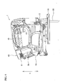
- a jigsaw 1 includes a housing 10, a blade 20, a base 30, a handle 40 and an insert receiving member 50.
- the jigsaw 1 is an example of a cutting machine according to the embodiment of the present invention.
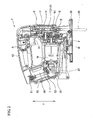
- a motor M is held as a drive source in a central portion of the housing 10, while a reciprocating mechanism 11 is held in a front portion of the housing 10.
- a fan F for cooling the motor M is mounted on the output shaft M1 of the motor M.
- the output shaft M1 is engaged with a drive gear 11A of the reciprocating mechanism 11.
- the output shaft M1 is rotatably supported by a bearing 12 mounted in the housing 10.
- the drive gear 11A is rotatably supported through a bearing by a shaft 13 which is secured in the housing 10.
- a working member 14 is fixed in an off-center position at the front of the drive gear 11A. The working member 14 revolves about the shaft 13 by the rotation of the drive gear 11A.
- a rod R is supported by the working member 14 in the front portion of the housing 10.
- the rod R moves in the up and down directions with the revolutions of the working member 14.
- the rod R is moved upward and downward to make one round trip every time the working member 14 revolves.
- the rod R has a lower end located outside the housing 10 and a blade mounting 15 is provided at the lower end.
- the top in Fig. 1 and Fig. 2 refers to the upper direction of the upper and lower directions Y of the housing 10, while the bottom refers to the lower direction of the upper and lower directions Y
- a blade 20 has a linear shape and is secured to the blade mounting 15.
- the blade 20 is an example of the cutting blade according to the embodiment of the present invention.
- the base 30 is attached to an underside of the housing 10 with a base setbolt B screwed to the underside.
- the base 30 is used to come into contact with the upper surface of a material to be cut (not shown).
- the handle 40 is formed on the top of the housing 10 when viewed from a side of the jigsaw 1.
- the upper surface of the handle 40 is slightly curved to be inclined downward in the rearward direction (in the left direction in Fig. 2 ).
- a switch S is held in the handle 40 and has a trigger 41 for supplying or stopping power to the motor M.
- the left side in Fig. 1 to Fig. 4 refers to rearward of the handle 40, while the right side refers to forward of the handle 40.
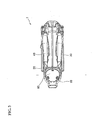
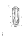
- the insert receiving member 50 has an approximately tubular shape having an opening 51 (see Fig. 4 ) formed at the upper surface, and is formed by recessing the housing 10.
- the inner surface of the insert receiving member 50 has a shape matched to the contour shape of a battery pack 60, so that the battery pack 60 can be inserted into the interior of the insert receiving member 50 through the opening 51 from above for installation.
- the insert receiving member 50 is situated at the rear of the handle 40 while being inclined toward the rear of the housing 10.
- the insert receiving member 50 is located lower than the handle 40 in the vertical direction Y, and is integrally combined with the rear end face of the handle 40.
- terminals T electrically connected to the motor M through lead wires extend beyond a bottom B1 of the insert receiving member 50 within the insert receiving member 50. While the battery pack 60 is inserted and installed to the insert receiving member 50, the terminals T can make an electric contact with an electrode plate of the battery pack 60. At this stage, an engaging portion 61 of the battery pack 60 is engaged with the inner surface of the insert receiving member 50, such that the upper surface of the battery pack 60 is located lower than the upper surface of the handle 40 in the vertical direction Y
- a discharge port 52 is provided in the lower end of the rear face of the insert receiving member 50 close to the lower end of the slope of the bottom B1.
- the discharge port 52 allows communication between the interior of the insert receiving member 50 and the outside of the housing 10.
- the discharge port 52 is provided in the rear face of the insert receiving member 50 so as to be placed at a distance from a cutting site of the material cut by the blade 20, so that dust particles produced at the cutting site are prevented from entering the interior of the insert receiving member 50 from the discharge port 52. Dust particles, rainwater and/or the like entering the interior of the insert receiving member 50 from the opening 51 are guided along the slope of the bottom B 1 to the discharge port 52.
- the discharge port 52 discharges the dust particles, rainwater and/or the like from the housing 10 to the outside.
- the lower end of the rear face of the insert receiving member 50 is an example of a lower end of an insert receiving member according to the present invention
- the discharge port 52 is an example of an opening according to the present invention.
- the interior shape (inner face) of the insert receiving member 50 is matched to the contour shape of the battery pack 60, the interior of the insert receiving member 50 serves as a guiding face when the batter pack 60 is inserted into/removed from the interior. Accordingly, if the battery pack 60 is slid along the interior from the opening 51, the battery pack 60 can be smoothly attached to/detached from the insert receiving member 50.
- the battery pack 60 which is a power source supplies power to the motor M to drive the motor M.
- the blade 20 together with the rod R, reciprocates in the vertical direction Y to cut the to-be-cut material.
- the jigsaw 1 since the jigsaw 1 according to the embodiment has the insert receiving member 50 formed in the housing 10 at the rear of handle 40, this eliminates the necessity to increase the dimensions of the handle 40 in accordance with the size of the battery pack 60, resulting in the jigsaw 1 with improved usability. In addition, since the battery pack 60 is inserted into the insert receiving member 50 from above, the battery pack 60 can be slid into the insert receiving member 50 with stability, resulting in easy installation of the battery pack 60 to the jigsaw 1.
- the insert receiving member 50 is coupled to the handle 40, the rigidity is improved.
- the rigidity of the insert receiving member 50 is combined with the rigidity of the battery pack 60 to provide further improved rigidity.
- the discharge port 52 is provided in the rear face of the insert receiving member 50 close to the lower end of the slope of the bottom B1, the dust particles, rainwater and/or the like entering the interior of the insert receiving member 50 can be guided along the slope of the bottom B 1 to the discharge port 52, and the can be discharged from the discharge port 52 to the outside of the housing 10.
- the present invention should be not limited to the aforementioned embodiment, and may be carried out by approximately changing partially the structure without departing from the gist of the invention.
- the aforementioned embodiment has described the insert receiving member 50 formed integrally with the rear end face of the handle 40.
- the invention is not so limited, and the insert receiving member 50 may be separated from the rear end face and be connected to the housing 10 at the rear of the handle 40.
- the insert receiving member 50 described above has the bottom inclined rearward of the housing 10, but it is not limited this.
- the insert receiving member may be connected to the housing while the insert receiving member itself may extend at the right angles to the housing 10. In this case, the dust particles and the like entering the interior of the insert receiving member 50 are pushed out from the discharge port 52 by the movement of air produced when the battery pack 60 is inserted into the insert receiving member, and accordingly will not be accumulated in the insert receiving member 50.
- the discharge port may be formed in the bottom B1, and a discharge passage may be provided to communicate with the discharge port and the outside of the housing 10 holding the motor M, such that the dust particles and the like can be discharged from the discharge port through the discharge passage to the outside of the housing.
- the present invention is applicable to any electrical power tool such as a cutter, a reciprocating saw and the like, as well as the jigsaw.
Abstract
Description
- This invention relates to a cutting machine including a handle provided on top of a housing accommodating a motor, and a cutting blade operated by the motor driven by a battery pack.
- For example, Japanese Laid-open Patent Application Publication No.
2008-173712 - However, since the above-described cutting machine is required to fit the handle with the battery pack, the dimensions of the handle are increased in accordance with the battery pack, causing reduced usability of the cutting machine. Further, when the battery pack is slid, in particular, from above to bottom for installation, the battery pack may possibly not be easily installed because the battery pack is not readily slid onto the handle with stability.
- The present invention has been made in view of the above circumstances and provides a cutting machine that provides increased usability and is capable of facilitating installation of a battery pack.
- A first aspect of the present invention provides a cutting machine comprising
a housing,
a motor that is accommodated in the housing,
a handle that is provided on top of housing,
a cutting blade that is operated by the motor driven by a battery pack which is a power source, and
an insert receiving member that is formed in the housing at the rear of the handle and has an open top end to allow the battery pack to be inserted into the insert receiving member through the open top end from above for installation. - In a second aspect of the invention, in the first aspect, the insert receiving member is integrally joined to the handle.
- In a third aspect of the invention, in the first or second aspect, the insert receiving member is disposed in a lower position than the handle in a vertical direction of the housing, and an upper surface of the battery pack is located in a lower position than an upper surface of the handle in the vertical direction when the battery pack is inserted and installed in the insert receiving member.
- In a fourth aspect of the invention, in the first aspect, the insert receiving member has an approximately tubular shape with an open top end and a closed bottom end, an inner shape of the insert receiving member is matched to a contour shape of the battery pack inserted and installed in the insert receiving member. In a fifth aspect of the invention, in the fourth aspect, an opening is formed in a lower end of the insert receiving member to make communication between an interior of the insert receiving member and the outside of the housing.
- With the cutting machine according to the first aspect, since the insert receiving member, into which the battery pack is inserted and installed, is provided in the housing at the rear of the handle, this eliminates the necessity to increase the dimensions of the handle in accordance with the battery pack, resulting in the cutting machine with improved usability. In addition, since the battery pack is inserted into the insert receiving member from above, the battery pack can be slid into the insert receiving member with stability, resulting in easy installation of the battery pack to the cutting machine.
- According to the second aspect, the insert receiving member is coupled to the handle to improve the rigidity. In addition, when the battery pack is inserted and installed into the insert receiving member, the rigidity of the insert receiving member is combined with the rigidity of the battery pack to provide further improved rigidity.
- According to the third aspect, even if the cutting machine falls with the handle facing downward, the upper surface of the handle collides with the floor first. Accordingly, at a drop of the cutting machine, the impact on the battery pack can be lessened.
- According to the fifth aspect, dust particles, rainwater and the like entering the interior of the insert receiving member can be removed from the opening to the outside of the housing. As a result, it is possible to prevent the accumulation of dust particles, rainwater and the like in the insert receiving member.]
-
-
Fig. 1 is a side view of a jigsaw according to an embodiment of the present invention. -
Fig. 2 is a sectional view of an important part of the jigsaw. -
Fig. 3 is a top view of the jigsaw with a battery pack inserted into an insert receiving member. -
Fig. 4 is a top view of the jigsaw after the battery pack is removed from the insert receiving member. - An embodiment of the present invention will be described below with reference to
Fig. 1 to Fig. 4 . Ajigsaw 1 includes ahousing 10, ablade 20, abase 30, ahandle 40 and an insert receivingmember 50. Thejigsaw 1 is an example of a cutting machine according to the embodiment of the present invention. - As illustrated in
Fig. 2 , a motor M is held as a drive source in a central portion of thehousing 10, while areciprocating mechanism 11 is held in a front portion of thehousing 10. A fan F for cooling the motor M is mounted on the output shaft M1 of the motor M. In addition, the output shaft M1 is engaged with adrive gear 11A of thereciprocating mechanism 11. The output shaft M1 is rotatably supported by a bearing 12 mounted in thehousing 10. Thedrive gear 11A is rotatably supported through a bearing by ashaft 13 which is secured in thehousing 10. A workingmember 14 is fixed in an off-center position at the front of thedrive gear 11A. The workingmember 14 revolves about theshaft 13 by the rotation of thedrive gear 11A. A rod R is supported by the workingmember 14 in the front portion of thehousing 10. The rod R moves in the up and down directions with the revolutions of the workingmember 14. The rod R is moved upward and downward to make one round trip every time the workingmember 14 revolves. The rod R has a lower end located outside thehousing 10 and ablade mounting 15 is provided at the lower end. The top inFig. 1 andFig. 2 refers to the upper direction of the upper and lower directions Y of thehousing 10, while the bottom refers to the lower direction of the upper and lower directions Y - A
blade 20 has a linear shape and is secured to theblade mounting 15. Theblade 20 is an example of the cutting blade according to the embodiment of the present invention. Thebase 30 is attached to an underside of thehousing 10 with a base setbolt B screwed to the underside. Thebase 30 is used to come into contact with the upper surface of a material to be cut (not shown). - The
handle 40 is formed on the top of thehousing 10 when viewed from a side of thejigsaw 1. The upper surface of thehandle 40 is slightly curved to be inclined downward in the rearward direction (in the left direction inFig. 2 ). A switch S is held in thehandle 40 and has atrigger 41 for supplying or stopping power to the motor M. The left side inFig. 1 to Fig. 4 refers to rearward of thehandle 40, while the right side refers to forward of thehandle 40. - The insert receiving
member 50 has an approximately tubular shape having an opening 51 (seeFig. 4 ) formed at the upper surface, and is formed by recessing thehousing 10. The inner surface of theinsert receiving member 50 has a shape matched to the contour shape of abattery pack 60, so that thebattery pack 60 can be inserted into the interior of theinsert receiving member 50 through theopening 51 from above for installation. The insert receivingmember 50 is situated at the rear of thehandle 40 while being inclined toward the rear of thehousing 10. Theinsert receiving member 50 is located lower than thehandle 40 in the vertical direction Y, and is integrally combined with the rear end face of thehandle 40. - As illustrated in
Fig. 2 andFig. 4 , terminals T electrically connected to the motor M through lead wires (not shown) extend beyond a bottom B1 of theinsert receiving member 50 within theinsert receiving member 50. While thebattery pack 60 is inserted and installed to theinsert receiving member 50, the terminals T can make an electric contact with an electrode plate of thebattery pack 60. At this stage, anengaging portion 61 of thebattery pack 60 is engaged with the inner surface of theinsert receiving member 50, such that the upper surface of thebattery pack 60 is located lower than the upper surface of thehandle 40 in the vertical direction Y - A
discharge port 52 is provided in the lower end of the rear face of theinsert receiving member 50 close to the lower end of the slope of the bottom B1. Thedischarge port 52 allows communication between the interior of theinsert receiving member 50 and the outside of thehousing 10. In the embodiment, thedischarge port 52 is provided in the rear face of theinsert receiving member 50 so as to be placed at a distance from a cutting site of the material cut by theblade 20, so that dust particles produced at the cutting site are prevented from entering the interior of theinsert receiving member 50 from thedischarge port 52. Dust particles, rainwater and/or the like entering the interior of theinsert receiving member 50 from theopening 51 are guided along the slope of thebottom B 1 to thedischarge port 52. As a result, thedischarge port 52 discharges the dust particles, rainwater and/or the like from thehousing 10 to the outside. Note that the lower end of the rear face of theinsert receiving member 50 is an example of a lower end of an insert receiving member according to the present invention, and thedischarge port 52 is an example of an opening according to the present invention. - In the embodiment, since the interior shape (inner face) of the
insert receiving member 50 is matched to the contour shape of thebattery pack 60, the interior of theinsert receiving member 50 serves as a guiding face when thebatter pack 60 is inserted into/removed from the interior. Accordingly, if thebattery pack 60 is slid along the interior from theopening 51, thebattery pack 60 can be smoothly attached to/detached from theinsert receiving member 50. - When the switch S is turned on by pressing the
trigger 41 toward thehandle 40, thebattery pack 60 which is a power source supplies power to the motor M to drive the motor M. In step with this, upon the rotation of thedrive gear 11A, theblade 20, together with the rod R, reciprocates in the vertical direction Y to cut the to-be-cut material. - Since the
jigsaw 1 according to the embodiment has theinsert receiving member 50 formed in thehousing 10 at the rear ofhandle 40, this eliminates the necessity to increase the dimensions of thehandle 40 in accordance with the size of thebattery pack 60, resulting in thejigsaw 1 with improved usability. In addition, since thebattery pack 60 is inserted into theinsert receiving member 50 from above, thebattery pack 60 can be slid into theinsert receiving member 50 with stability, resulting in easy installation of thebattery pack 60 to thejigsaw 1. - Further, since the
insert receiving member 50 is coupled to thehandle 40, the rigidity is improved. In addition, when thebattery pack 60 is inserted and installed into theinsert receiving member 50, the rigidity of theinsert receiving member 50 is combined with the rigidity of thebattery pack 60 to provide further improved rigidity. - Even if the
jigsaw 1 falls with thehandle 40 facing downward, the upper surface of thehandle 40 collides with the floor first. Therefore, the impact on thebattery pack 60 can be lessened. - In addition, since the
discharge port 52 is provided in the rear face of theinsert receiving member 50 close to the lower end of the slope of the bottom B1, the dust particles, rainwater and/or the like entering the interior of theinsert receiving member 50 can be guided along the slope of thebottom B 1 to thedischarge port 52, and the can be discharged from thedischarge port 52 to the outside of thehousing 10. - The present invention should be not limited to the aforementioned embodiment, and may be carried out by approximately changing partially the structure without departing from the gist of the invention. For example, the aforementioned embodiment has described the
insert receiving member 50 formed integrally with the rear end face of thehandle 40. However, the invention is not so limited, and theinsert receiving member 50 may be separated from the rear end face and be connected to thehousing 10 at the rear of thehandle 40. Theinsert receiving member 50 described above has the bottom inclined rearward of thehousing 10, but it is not limited this. The insert receiving member may be connected to the housing while the insert receiving member itself may extend at the right angles to thehousing 10. In this case, the dust particles and the like entering the interior of theinsert receiving member 50 are pushed out from thedischarge port 52 by the movement of air produced when thebattery pack 60 is inserted into the insert receiving member, and accordingly will not be accumulated in theinsert receiving member 50. - Unlike the aforementioned embodiment, the discharge port may be formed in the bottom B1, and a discharge passage may be provided to communicate with the discharge port and the outside of the
housing 10 holding the motor M, such that the dust particles and the like can be discharged from the discharge port through the discharge passage to the outside of the housing. - The present invention is applicable to any electrical power tool such as a cutter, a reciprocating saw and the like, as well as the jigsaw.
- It is explicitly stated that all features disclosed in the description and/or the claims are intended to be disclosed separately and independently from each other for the purpose of original disclosure as well as for the purpose of restricting the claimed invention independent of the composition of the features in the embodiments and/or the claims. It is explicitly stated that all value ranges or indications of groups of entities disclose every possible intermediate value or intermediate entity for the purpose of original disclosure as well as for the purpose of restricting the claimed invention, in particular as limits of value ranges.
Claims (9)
- A cutting machine (1) comprising a handle (40) provided on top of a housing (10) accommodating a motor (M), and a cutting blade (20) operated by the motor (M) driven by a battery pack (60) which is a power source,
characterized in that
an insert receiving member (50) is formed in the housing (10) at the rear of the handle (40) and has an open top end to allow the battery pack (60) to be inserted into the insert receiving member from above for installation. - The cutting machine (1) according to claim 1, wherein the insert receiving member (50) is integrally joined to the handle (40).
- The cutting machine (1) according to claim 1 or 2, wherein the insert receiving member (50) is disposed in a lower position than the handle (40) in the vertical direction (Y) of the housing (10), and an upper surface of the battery pack (60) is located in a lower position than an upper surface of the handle (40) in the vertical direction (Y) when the battery pack (60) is inserted and installed in the insert receiving member (50).
- The cutting machine (1) according to any one of claims 1 to 3, wherein the insert receiving member (50) has an approximately tubular shape with an open top end and a closed bottom end, an inner shape of the insert receiving member (50) is matched to a contour shape of the battery pack (60) inserted and installed in the insert receiving member (50).
- The cutting machine (1) according to any one of claims 1 to 4, wherein the insert receiving member (50) is provided in the housing (10) while being inclined downward in the rear direction of the housing (10).
- The cutting machine (1) according to any one of claims 1 to 5, wherein a terminal (T) electrically connected to the motor (M) extends into an interior of the insert receiving member (50) beyond a bottom (B1) of the insert receiving member (50), and an electrode plate of the battery pack (60) inserted and installed in the interior comes into electric contact with the terminal (T).
- The cutting machine (1) according to any one of claims 1 to 6, wherein an opening (52) is formed in a lower end of the insert receiving member (50) to make communication between an interior of the insert receiving member (50) and the outside of the housing (10).
- The cutting machine (1) according to claim 7, wherein the opening (52) is provided in a lower end of a rear face of the insert receiving member (50).
- The cutting machine (1) according to claim 7 or 8, wherein the opening (52) is provided in a lower end of a rear face of the insert receiving member (50) close to a lower end of a slope of the bottom of the insert receiving member (50).
Applications Claiming Priority (1)
| Application Number | Priority Date | Filing Date | Title |
|---|---|---|---|
| JP2010264038A JP5618784B2 (en) | 2010-11-26 | 2010-11-26 | Cutting machine |
Publications (3)
| Publication Number | Publication Date |
|---|---|
| EP2457701A2 true EP2457701A2 (en) | 2012-05-30 |
| EP2457701A3 EP2457701A3 (en) | 2013-06-19 |
| EP2457701B1 EP2457701B1 (en) | 2014-10-29 |
Family
ID=44936196
Family Applications (1)
| Application Number | Title | Priority Date | Filing Date |
|---|---|---|---|
| EP11187482.2A Active EP2457701B1 (en) | 2010-11-26 | 2011-11-02 | Jigsaw |
Country Status (5)
| Country | Link |
|---|---|
| US (1) | US20120131803A1 (en) |
| EP (1) | EP2457701B1 (en) |
| JP (1) | JP5618784B2 (en) |
| CN (1) | CN102528771B (en) |
| RU (1) | RU2567074C2 (en) |
Families Citing this family (4)
| Publication number | Priority date | Publication date | Assignee | Title |
|---|---|---|---|---|
| JP6193895B2 (en) * | 2013-02-01 | 2017-09-06 | 株式会社マキタ | Cutting tool |
| JP2014148025A (en) * | 2013-02-01 | 2014-08-21 | Makita Corp | Reciprocally cutting electric tool |
| JP6824755B2 (en) | 2017-01-13 | 2021-02-03 | 株式会社マキタ | Jigsaw |
| JP6924577B2 (en) | 2017-01-13 | 2021-08-25 | 株式会社マキタ | Jigsaw |
Citations (1)
| Publication number | Priority date | Publication date | Assignee | Title |
|---|---|---|---|---|
| JP2008173712A (en) | 2007-01-18 | 2008-07-31 | Hitachi Koki Co Ltd | Cordless power tool |
Family Cites Families (13)
| Publication number | Priority date | Publication date | Assignee | Title |
|---|---|---|---|---|
| JPH07112078A (en) * | 1993-10-20 | 1995-05-02 | Matsushita Electric Works Ltd | Cutting tool |
| JPH09164501A (en) * | 1995-12-15 | 1997-06-24 | Matsushita Electric Works Ltd | Electric circular saw |
| JP3558880B2 (en) * | 1998-07-09 | 2004-08-25 | 株式会社マキタ | Tabletop marunoco board |
| US6996909B1 (en) * | 1998-08-13 | 2006-02-14 | Black & Decker Inc. | Battery powered circular saw |
| US6161293A (en) * | 1998-08-14 | 2000-12-19 | One World Technologies, Inc. | Battery powered circular saw |
| DE10318947A1 (en) * | 2003-04-26 | 2004-11-18 | Robert Bosch Gmbh | Electric hand tool with battery pack |
| DE10348693B4 (en) * | 2003-10-16 | 2009-06-04 | Hilti Aktiengesellschaft | Electrical connection device for hand tool accessories |
| JP4977533B2 (en) * | 2007-06-07 | 2012-07-18 | 株式会社マキタ | Portable electric tool |
| CN101138848A (en) * | 2007-10-24 | 2008-03-12 | 徐森良 | Electric single-page paper knife |
| JP5221158B2 (en) * | 2008-02-06 | 2013-06-26 | 株式会社マキタ | Electric tool and its remote-control holder |
| WO2009111747A2 (en) * | 2008-03-07 | 2009-09-11 | Milwaukee Electric Tool Corporation | Portable battery-powered reciprocating saw |
| DE102009012181A1 (en) * | 2009-02-27 | 2010-09-02 | Andreas Stihl Ag & Co. Kg | Battery-powered, hand-held implement with a throttle |
| DE102009012175A1 (en) * | 2009-02-27 | 2010-09-02 | Andreas Stihl Ag & Co. Kg | Electrical appliance with a battery pack |
-
2010
- 2010-11-26 JP JP2010264038A patent/JP5618784B2/en active Active
-
2011
- 2011-10-25 CN CN201110331035.XA patent/CN102528771B/en active Active
- 2011-10-26 US US13/281,728 patent/US20120131803A1/en not_active Abandoned
- 2011-11-02 EP EP11187482.2A patent/EP2457701B1/en active Active
- 2011-11-24 RU RU2011147932/02A patent/RU2567074C2/en active
Patent Citations (1)
| Publication number | Priority date | Publication date | Assignee | Title |
|---|---|---|---|---|
| JP2008173712A (en) | 2007-01-18 | 2008-07-31 | Hitachi Koki Co Ltd | Cordless power tool |
Also Published As
| Publication number | Publication date |
|---|---|
| US20120131803A1 (en) | 2012-05-31 |
| CN102528771B (en) | 2015-04-22 |
| EP2457701A3 (en) | 2013-06-19 |
| JP5618784B2 (en) | 2014-11-05 |
| RU2567074C2 (en) | 2015-10-27 |
| CN102528771A (en) | 2012-07-04 |
| JP2012111021A (en) | 2012-06-14 |
| RU2011147932A (en) | 2013-05-27 |
| EP2457701B1 (en) | 2014-10-29 |
Similar Documents
| Publication | Publication Date | Title |
|---|---|---|
| US20180236572A1 (en) | Reciprocating saw | |
| US7275326B2 (en) | Portable electric cutting apparatus | |
| US20150165640A1 (en) | Battery Pack Operated Hand-Held Power Tool | |
| EP2712712A2 (en) | Electric tools | |
| US10220457B2 (en) | Cutting device | |
| EP2457701B1 (en) | Jigsaw | |
| CN112136467B (en) | Electric hand-held working machine | |
| HK1100075A1 (en) | Wet razor and electric trimmer assembly | |
| EP2813310A1 (en) | Saw with blower housing | |
| JP6953136B2 (en) | Cutting tool | |
| CN101641192B (en) | Cutter | |
| EP2668840B1 (en) | Electrically powered garden tool | |
| EP2527071A1 (en) | Cutting tool with dust preventing device | |
| US20120184191A1 (en) | Electric power tool, in particular a grinding or polishing machine | |
| EP2679325B1 (en) | Jigsaw | |
| JP6736434B2 (en) | Portable processing machine | |
| US20210362252A1 (en) | Portable circular saw for cutting metal | |
| JP4962902B2 (en) | Portable belt polishing machine | |
| JP2021030395A (en) | Cutting machine | |
| EP2463049B1 (en) | Cutting machine | |
| EP2564964A1 (en) | Cutoff tool | |
| US20100011598A1 (en) | Hand-held power tool for driving a disc-shaped working tool | |
| CN213655199U (en) | Blower fan | |
| JP5062123B2 (en) | Portable cutting machine | |
| JP2023082582A (en) | Electric tool |
Legal Events
| Date | Code | Title | Description |
|---|---|---|---|
| PUAI | Public reference made under article 153(3) epc to a published international application that has entered the european phase |
Free format text: ORIGINAL CODE: 0009012 |
|
| AK | Designated contracting states |
Kind code of ref document: A2 Designated state(s): AL AT BE BG CH CY CZ DE DK EE ES FI FR GB GR HR HU IE IS IT LI LT LU LV MC MK MT NL NO PL PT RO RS SE SI SK SM TR |
|
| AX | Request for extension of the european patent |
Extension state: BA ME |
|
| PUAL | Search report despatched |
Free format text: ORIGINAL CODE: 0009013 |
|
| AK | Designated contracting states |
Kind code of ref document: A3 Designated state(s): AL AT BE BG CH CY CZ DE DK EE ES FI FR GB GR HR HU IE IS IT LI LT LU LV MC MK MT NL NO PL PT RO RS SE SI SK SM TR |
|
| AX | Request for extension of the european patent |
Extension state: BA ME |
|
| RIC1 | Information provided on ipc code assigned before grant |
Ipc: B23D 51/00 20060101ALI20130516BHEP Ipc: B25F 5/02 20060101AFI20130516BHEP |
|
| 17P | Request for examination filed |
Effective date: 20131213 |
|
| RBV | Designated contracting states (corrected) |
Designated state(s): AL AT BE BG CH CY CZ DE DK EE ES FI FR GB GR HR HU IE IS IT LI LT LU LV MC MK MT NL NO PL PT RO RS SE SI SK SM TR |
|
| 17Q | First examination report despatched |
Effective date: 20140204 |
|
| GRAP | Despatch of communication of intention to grant a patent |
Free format text: ORIGINAL CODE: EPIDOSNIGR1 |
|
| INTG | Intention to grant announced |
Effective date: 20140729 |
|
| GRAS | Grant fee paid |
Free format text: ORIGINAL CODE: EPIDOSNIGR3 |
|
| GRAA | (expected) grant |
Free format text: ORIGINAL CODE: 0009210 |
|
| AK | Designated contracting states |
Kind code of ref document: B1 Designated state(s): AL AT BE BG CH CY CZ DE DK EE ES FI FR GB GR HR HU IE IS IT LI LT LU LV MC MK MT NL NO PL PT RO RS SE SI SK SM TR |
|
| REG | Reference to a national code |
Ref country code: GB Ref legal event code: FG4D |
|
| REG | Reference to a national code |
Ref country code: CH Ref legal event code: EP |
|
| REG | Reference to a national code |
Ref country code: AT Ref legal event code: REF Ref document number: 693332 Country of ref document: AT Kind code of ref document: T Effective date: 20141115 |
|
| REG | Reference to a national code |
Ref country code: IE Ref legal event code: FG4D |
|
| REG | Reference to a national code |
Ref country code: DE Ref legal event code: R096 Ref document number: 602011010904 Country of ref document: DE Effective date: 20141211 |
|
| REG | Reference to a national code |
Ref country code: AT Ref legal event code: MK05 Ref document number: 693332 Country of ref document: AT Kind code of ref document: T Effective date: 20141029 |
|
| REG | Reference to a national code |
Ref country code: NL Ref legal event code: VDEP Effective date: 20141029 |
|
| REG | Reference to a national code |
Ref country code: LT Ref legal event code: MG4D |
|
| PG25 | Lapsed in a contracting state [announced via postgrant information from national office to epo] |
Ref country code: FI Free format text: LAPSE BECAUSE OF FAILURE TO SUBMIT A TRANSLATION OF THE DESCRIPTION OR TO PAY THE FEE WITHIN THE PRESCRIBED TIME-LIMIT Effective date: 20141029 Ref country code: NO Free format text: LAPSE BECAUSE OF FAILURE TO SUBMIT A TRANSLATION OF THE DESCRIPTION OR TO PAY THE FEE WITHIN THE PRESCRIBED TIME-LIMIT Effective date: 20150129 Ref country code: LT Free format text: LAPSE BECAUSE OF FAILURE TO SUBMIT A TRANSLATION OF THE DESCRIPTION OR TO PAY THE FEE WITHIN THE PRESCRIBED TIME-LIMIT Effective date: 20141029 Ref country code: ES Free format text: LAPSE BECAUSE OF FAILURE TO SUBMIT A TRANSLATION OF THE DESCRIPTION OR TO PAY THE FEE WITHIN THE PRESCRIBED TIME-LIMIT Effective date: 20141029 Ref country code: PT Free format text: LAPSE BECAUSE OF FAILURE TO SUBMIT A TRANSLATION OF THE DESCRIPTION OR TO PAY THE FEE WITHIN THE PRESCRIBED TIME-LIMIT Effective date: 20150302 Ref country code: NL Free format text: LAPSE BECAUSE OF FAILURE TO SUBMIT A TRANSLATION OF THE DESCRIPTION OR TO PAY THE FEE WITHIN THE PRESCRIBED TIME-LIMIT Effective date: 20141029 Ref country code: IS Free format text: LAPSE BECAUSE OF FAILURE TO SUBMIT A TRANSLATION OF THE DESCRIPTION OR TO PAY THE FEE WITHIN THE PRESCRIBED TIME-LIMIT Effective date: 20150228 |
|
| PG25 | Lapsed in a contracting state [announced via postgrant information from national office to epo] |
Ref country code: CY Free format text: LAPSE BECAUSE OF FAILURE TO SUBMIT A TRANSLATION OF THE DESCRIPTION OR TO PAY THE FEE WITHIN THE PRESCRIBED TIME-LIMIT Effective date: 20141029 Ref country code: LV Free format text: LAPSE BECAUSE OF FAILURE TO SUBMIT A TRANSLATION OF THE DESCRIPTION OR TO PAY THE FEE WITHIN THE PRESCRIBED TIME-LIMIT Effective date: 20141029 Ref country code: GR Free format text: LAPSE BECAUSE OF FAILURE TO SUBMIT A TRANSLATION OF THE DESCRIPTION OR TO PAY THE FEE WITHIN THE PRESCRIBED TIME-LIMIT Effective date: 20150130 Ref country code: RS Free format text: LAPSE BECAUSE OF FAILURE TO SUBMIT A TRANSLATION OF THE DESCRIPTION OR TO PAY THE FEE WITHIN THE PRESCRIBED TIME-LIMIT Effective date: 20141029 Ref country code: SE Free format text: LAPSE BECAUSE OF FAILURE TO SUBMIT A TRANSLATION OF THE DESCRIPTION OR TO PAY THE FEE WITHIN THE PRESCRIBED TIME-LIMIT Effective date: 20141029 Ref country code: HR Free format text: LAPSE BECAUSE OF FAILURE TO SUBMIT A TRANSLATION OF THE DESCRIPTION OR TO PAY THE FEE WITHIN THE PRESCRIBED TIME-LIMIT Effective date: 20141029 Ref country code: AT Free format text: LAPSE BECAUSE OF FAILURE TO SUBMIT A TRANSLATION OF THE DESCRIPTION OR TO PAY THE FEE WITHIN THE PRESCRIBED TIME-LIMIT Effective date: 20141029 Ref country code: PL Free format text: LAPSE BECAUSE OF FAILURE TO SUBMIT A TRANSLATION OF THE DESCRIPTION OR TO PAY THE FEE WITHIN THE PRESCRIBED TIME-LIMIT Effective date: 20141029 |
|
| PG25 | Lapsed in a contracting state [announced via postgrant information from national office to epo] |
Ref country code: BE Free format text: LAPSE BECAUSE OF NON-PAYMENT OF DUE FEES Effective date: 20141130 |
|
| REG | Reference to a national code |
Ref country code: CH Ref legal event code: PL |
|
| REG | Reference to a national code |
Ref country code: DE Ref legal event code: R097 Ref document number: 602011010904 Country of ref document: DE |
|
| PG25 | Lapsed in a contracting state [announced via postgrant information from national office to epo] |
Ref country code: RO Free format text: LAPSE BECAUSE OF FAILURE TO SUBMIT A TRANSLATION OF THE DESCRIPTION OR TO PAY THE FEE WITHIN THE PRESCRIBED TIME-LIMIT Effective date: 20141029 Ref country code: SK Free format text: LAPSE BECAUSE OF FAILURE TO SUBMIT A TRANSLATION OF THE DESCRIPTION OR TO PAY THE FEE WITHIN THE PRESCRIBED TIME-LIMIT Effective date: 20141029 Ref country code: LI Free format text: LAPSE BECAUSE OF NON-PAYMENT OF DUE FEES Effective date: 20141130 Ref country code: CH Free format text: LAPSE BECAUSE OF NON-PAYMENT OF DUE FEES Effective date: 20141130 Ref country code: DK Free format text: LAPSE BECAUSE OF FAILURE TO SUBMIT A TRANSLATION OF THE DESCRIPTION OR TO PAY THE FEE WITHIN THE PRESCRIBED TIME-LIMIT Effective date: 20141029 Ref country code: EE Free format text: LAPSE BECAUSE OF FAILURE TO SUBMIT A TRANSLATION OF THE DESCRIPTION OR TO PAY THE FEE WITHIN THE PRESCRIBED TIME-LIMIT Effective date: 20141029 Ref country code: MC Free format text: LAPSE BECAUSE OF FAILURE TO SUBMIT A TRANSLATION OF THE DESCRIPTION OR TO PAY THE FEE WITHIN THE PRESCRIBED TIME-LIMIT Effective date: 20141029 Ref country code: CZ Free format text: LAPSE BECAUSE OF FAILURE TO SUBMIT A TRANSLATION OF THE DESCRIPTION OR TO PAY THE FEE WITHIN THE PRESCRIBED TIME-LIMIT Effective date: 20141029 |
|
| REG | Reference to a national code |
Ref country code: IE Ref legal event code: MM4A |
|
| PG25 | Lapsed in a contracting state [announced via postgrant information from national office to epo] |
Ref country code: IT Free format text: LAPSE BECAUSE OF FAILURE TO SUBMIT A TRANSLATION OF THE DESCRIPTION OR TO PAY THE FEE WITHIN THE PRESCRIBED TIME-LIMIT Effective date: 20141029 |
|
| PLBE | No opposition filed within time limit |
Free format text: ORIGINAL CODE: 0009261 |
|
| STAA | Information on the status of an ep patent application or granted ep patent |
Free format text: STATUS: NO OPPOSITION FILED WITHIN TIME LIMIT |
|
| 26N | No opposition filed |
Effective date: 20150730 |
|
| PG25 | Lapsed in a contracting state [announced via postgrant information from national office to epo] |
Ref country code: IE Free format text: LAPSE BECAUSE OF NON-PAYMENT OF DUE FEES Effective date: 20141102 |
|
| REG | Reference to a national code |
Ref country code: FR Ref legal event code: PLFP Year of fee payment: 5 |
|
| PG25 | Lapsed in a contracting state [announced via postgrant information from national office to epo] |
Ref country code: SI Free format text: LAPSE BECAUSE OF FAILURE TO SUBMIT A TRANSLATION OF THE DESCRIPTION OR TO PAY THE FEE WITHIN THE PRESCRIBED TIME-LIMIT Effective date: 20141029 |
|
| PG25 | Lapsed in a contracting state [announced via postgrant information from national office to epo] |
Ref country code: SM Free format text: LAPSE BECAUSE OF FAILURE TO SUBMIT A TRANSLATION OF THE DESCRIPTION OR TO PAY THE FEE WITHIN THE PRESCRIBED TIME-LIMIT Effective date: 20141029 |
|
| PG25 | Lapsed in a contracting state [announced via postgrant information from national office to epo] |
Ref country code: BG Free format text: LAPSE BECAUSE OF FAILURE TO SUBMIT A TRANSLATION OF THE DESCRIPTION OR TO PAY THE FEE WITHIN THE PRESCRIBED TIME-LIMIT Effective date: 20141029 |
|
| PG25 | Lapsed in a contracting state [announced via postgrant information from national office to epo] |
Ref country code: LU Free format text: LAPSE BECAUSE OF NON-PAYMENT OF DUE FEES Effective date: 20141102 Ref country code: HU Free format text: LAPSE BECAUSE OF FAILURE TO SUBMIT A TRANSLATION OF THE DESCRIPTION OR TO PAY THE FEE WITHIN THE PRESCRIBED TIME-LIMIT; INVALID AB INITIO Effective date: 20111102 Ref country code: TR Free format text: LAPSE BECAUSE OF FAILURE TO SUBMIT A TRANSLATION OF THE DESCRIPTION OR TO PAY THE FEE WITHIN THE PRESCRIBED TIME-LIMIT Effective date: 20141029 Ref country code: MT Free format text: LAPSE BECAUSE OF FAILURE TO SUBMIT A TRANSLATION OF THE DESCRIPTION OR TO PAY THE FEE WITHIN THE PRESCRIBED TIME-LIMIT Effective date: 20141029 |
|
| REG | Reference to a national code |
Ref country code: FR Ref legal event code: PLFP Year of fee payment: 6 |
|
| REG | Reference to a national code |
Ref country code: FR Ref legal event code: PLFP Year of fee payment: 7 |
|
| PG25 | Lapsed in a contracting state [announced via postgrant information from national office to epo] |
Ref country code: MK Free format text: LAPSE BECAUSE OF FAILURE TO SUBMIT A TRANSLATION OF THE DESCRIPTION OR TO PAY THE FEE WITHIN THE PRESCRIBED TIME-LIMIT Effective date: 20141029 |
|
| REG | Reference to a national code |
Ref country code: FR Ref legal event code: PLFP Year of fee payment: 8 |
|
| PG25 | Lapsed in a contracting state [announced via postgrant information from national office to epo] |
Ref country code: AL Free format text: LAPSE BECAUSE OF FAILURE TO SUBMIT A TRANSLATION OF THE DESCRIPTION OR TO PAY THE FEE WITHIN THE PRESCRIBED TIME-LIMIT Effective date: 20141029 |
|
| PGFP | Annual fee paid to national office [announced via postgrant information from national office to epo] |
Ref country code: GB Payment date: 20230928 Year of fee payment: 13 |
|
| PGFP | Annual fee paid to national office [announced via postgrant information from national office to epo] |
Ref country code: FR Payment date: 20230929 Year of fee payment: 13 |
|
| PGFP | Annual fee paid to national office [announced via postgrant information from national office to epo] |
Ref country code: DE Payment date: 20230929 Year of fee payment: 13 |