EP2457654A1 - Highly efficient catalyst using precious metal - Google Patents
Highly efficient catalyst using precious metal Download PDFInfo
- Publication number
- EP2457654A1 EP2457654A1 EP11175283A EP11175283A EP2457654A1 EP 2457654 A1 EP2457654 A1 EP 2457654A1 EP 11175283 A EP11175283 A EP 11175283A EP 11175283 A EP11175283 A EP 11175283A EP 2457654 A1 EP2457654 A1 EP 2457654A1
- Authority
- EP
- European Patent Office
- Prior art keywords
- catalyst
- precious metal
- channels
- exhaust gas
- present
- Prior art date
- Legal status (The legal status is an assumption and is not a legal conclusion. Google has not performed a legal analysis and makes no representation as to the accuracy of the status listed.)
- Ceased
Links
Images


Classifications
-
- B—PERFORMING OPERATIONS; TRANSPORTING
- B01—PHYSICAL OR CHEMICAL PROCESSES OR APPARATUS IN GENERAL
- B01J—CHEMICAL OR PHYSICAL PROCESSES, e.g. CATALYSIS OR COLLOID CHEMISTRY; THEIR RELEVANT APPARATUS
- B01J23/00—Catalysts comprising metals or metal oxides or hydroxides, not provided for in group B01J21/00
- B01J23/38—Catalysts comprising metals or metal oxides or hydroxides, not provided for in group B01J21/00 of noble metals
-
- B—PERFORMING OPERATIONS; TRANSPORTING
- B01—PHYSICAL OR CHEMICAL PROCESSES OR APPARATUS IN GENERAL
- B01D—SEPARATION
- B01D53/00—Separation of gases or vapours; Recovering vapours of volatile solvents from gases; Chemical or biological purification of waste gases, e.g. engine exhaust gases, smoke, fumes, flue gases, aerosols
- B01D53/34—Chemical or biological purification of waste gases
- B01D53/92—Chemical or biological purification of waste gases of engine exhaust gases
- B01D53/94—Chemical or biological purification of waste gases of engine exhaust gases by catalytic processes
-
- B—PERFORMING OPERATIONS; TRANSPORTING
- B01—PHYSICAL OR CHEMICAL PROCESSES OR APPARATUS IN GENERAL
- B01J—CHEMICAL OR PHYSICAL PROCESSES, e.g. CATALYSIS OR COLLOID CHEMISTRY; THEIR RELEVANT APPARATUS
- B01J29/00—Catalysts comprising molecular sieves
- B01J29/03—Catalysts comprising molecular sieves not having base-exchange properties
- B01J29/0308—Mesoporous materials not having base exchange properties, e.g. Si-MCM-41
-
- B—PERFORMING OPERATIONS; TRANSPORTING
- B01—PHYSICAL OR CHEMICAL PROCESSES OR APPARATUS IN GENERAL
- B01J—CHEMICAL OR PHYSICAL PROCESSES, e.g. CATALYSIS OR COLLOID CHEMISTRY; THEIR RELEVANT APPARATUS
- B01J35/00—Catalysts, in general, characterised by their form or physical properties
- B01J35/50—Catalysts, in general, characterised by their form or physical properties characterised by their shape or configuration
- B01J35/56—Foraminous structures having flow-through passages or channels, e.g. grids or three-dimensional [3D] monoliths
- B01J35/57—Honeycombs
-
- B—PERFORMING OPERATIONS; TRANSPORTING
- B01—PHYSICAL OR CHEMICAL PROCESSES OR APPARATUS IN GENERAL
- B01J—CHEMICAL OR PHYSICAL PROCESSES, e.g. CATALYSIS OR COLLOID CHEMISTRY; THEIR RELEVANT APPARATUS
- B01J37/00—Processes, in general, for preparing catalysts; Processes, in general, for activation of catalysts
- B01J37/02—Impregnation, coating or precipitation
- B01J37/0215—Coating
-
- C—CHEMISTRY; METALLURGY
- C04—CEMENTS; CONCRETE; ARTIFICIAL STONE; CERAMICS; REFRACTORIES
- C04B—LIME, MAGNESIA; SLAG; CEMENTS; COMPOSITIONS THEREOF, e.g. MORTARS, CONCRETE OR LIKE BUILDING MATERIALS; ARTIFICIAL STONE; CERAMICS; REFRACTORIES; TREATMENT OF NATURAL STONE
- C04B35/00—Shaped ceramic products characterised by their composition; Ceramics compositions; Processing powders of inorganic compounds preparatory to the manufacturing of ceramic products
- C04B35/01—Shaped ceramic products characterised by their composition; Ceramics compositions; Processing powders of inorganic compounds preparatory to the manufacturing of ceramic products based on oxide ceramics
- C04B35/10—Shaped ceramic products characterised by their composition; Ceramics compositions; Processing powders of inorganic compounds preparatory to the manufacturing of ceramic products based on oxide ceramics based on aluminium oxide
-
- C—CHEMISTRY; METALLURGY
- C04—CEMENTS; CONCRETE; ARTIFICIAL STONE; CERAMICS; REFRACTORIES
- C04B—LIME, MAGNESIA; SLAG; CEMENTS; COMPOSITIONS THEREOF, e.g. MORTARS, CONCRETE OR LIKE BUILDING MATERIALS; ARTIFICIAL STONE; CERAMICS; REFRACTORIES; TREATMENT OF NATURAL STONE
- C04B35/00—Shaped ceramic products characterised by their composition; Ceramics compositions; Processing powders of inorganic compounds preparatory to the manufacturing of ceramic products
- C04B35/01—Shaped ceramic products characterised by their composition; Ceramics compositions; Processing powders of inorganic compounds preparatory to the manufacturing of ceramic products based on oxide ceramics
- C04B35/14—Shaped ceramic products characterised by their composition; Ceramics compositions; Processing powders of inorganic compounds preparatory to the manufacturing of ceramic products based on oxide ceramics based on silica
-
- C—CHEMISTRY; METALLURGY
- C04—CEMENTS; CONCRETE; ARTIFICIAL STONE; CERAMICS; REFRACTORIES
- C04B—LIME, MAGNESIA; SLAG; CEMENTS; COMPOSITIONS THEREOF, e.g. MORTARS, CONCRETE OR LIKE BUILDING MATERIALS; ARTIFICIAL STONE; CERAMICS; REFRACTORIES; TREATMENT OF NATURAL STONE
- C04B38/00—Porous mortars, concrete, artificial stone or ceramic ware; Preparation thereof
- C04B38/0006—Honeycomb structures
- C04B38/0009—Honeycomb structures characterised by features relating to the cell walls, e.g. wall thickness or distribution of pores in the walls
-
- F—MECHANICAL ENGINEERING; LIGHTING; HEATING; WEAPONS; BLASTING
- F01—MACHINES OR ENGINES IN GENERAL; ENGINE PLANTS IN GENERAL; STEAM ENGINES
- F01N—GAS-FLOW SILENCERS OR EXHAUST APPARATUS FOR MACHINES OR ENGINES IN GENERAL; GAS-FLOW SILENCERS OR EXHAUST APPARATUS FOR INTERNAL-COMBUSTION ENGINES
- F01N3/00—Exhaust or silencing apparatus having means for purifying, rendering innocuous, or otherwise treating exhaust
- F01N3/08—Exhaust or silencing apparatus having means for purifying, rendering innocuous, or otherwise treating exhaust for rendering innocuous
- F01N3/10—Exhaust or silencing apparatus having means for purifying, rendering innocuous, or otherwise treating exhaust for rendering innocuous by thermal or catalytic conversion of noxious components of exhaust
- F01N3/24—Exhaust or silencing apparatus having means for purifying, rendering innocuous, or otherwise treating exhaust for rendering innocuous by thermal or catalytic conversion of noxious components of exhaust characterised by constructional aspects of converting apparatus
- F01N3/28—Construction of catalytic reactors
- F01N3/2803—Construction of catalytic reactors characterised by structure, by material or by manufacturing of catalyst support
- F01N3/2825—Ceramics
- F01N3/2828—Ceramic multi-channel monoliths, e.g. honeycombs
-
- B—PERFORMING OPERATIONS; TRANSPORTING
- B01—PHYSICAL OR CHEMICAL PROCESSES OR APPARATUS IN GENERAL
- B01J—CHEMICAL OR PHYSICAL PROCESSES, e.g. CATALYSIS OR COLLOID CHEMISTRY; THEIR RELEVANT APPARATUS
- B01J35/00—Catalysts, in general, characterised by their form or physical properties
- B01J35/60—Catalysts, in general, characterised by their form or physical properties characterised by their surface properties or porosity
- B01J35/64—Pore diameter
- B01J35/647—2-50 nm
-
- F—MECHANICAL ENGINEERING; LIGHTING; HEATING; WEAPONS; BLASTING
- F01—MACHINES OR ENGINES IN GENERAL; ENGINE PLANTS IN GENERAL; STEAM ENGINES
- F01N—GAS-FLOW SILENCERS OR EXHAUST APPARATUS FOR MACHINES OR ENGINES IN GENERAL; GAS-FLOW SILENCERS OR EXHAUST APPARATUS FOR INTERNAL-COMBUSTION ENGINES
- F01N2330/00—Structure of catalyst support or particle filter
- F01N2330/30—Honeycomb supports characterised by their structural details
- F01N2330/38—Honeycomb supports characterised by their structural details flow channels with means to enhance flow mixing,(e.g. protrusions or projections)
Definitions
- the present invention relates to a catalyst using a precious metal. More particularly, the present invention relates to a highly efficient catalyst using a three-dimensional porous structure as a supporting material for the precious metal in order to prevent an inaccessible region of the precious metal from being generated, and further improve the diffusion of exhaust gas.
- catalysts coated with precious metals such as platinum (Pt), palladium (Pd), and rhodium (Rh) are used for removing noxious substances from the exhaust gas of vehicles. These catalysts remove the noxious substances from the exhaust gas and purify the exhaust gas by promoting decomposition of the hydrocarbons, oxidization of the carbon monoxide, and reduction of the nitrogen oxide.
- a catalyst uniformly coated with a precious metal in a supporting material as a purifying catalyst of exhaust gas has been published.
- the catalyst is manufactured by coating catalytic substances including the expensive precious metal on a supporting material shaped as a honeycomb in order to increase the contact area between the catalyst and the exhaust gas, and thus to increase the reaction area.
- square cells are used as the unit cells of the honeycomb supporting material.
- using square cells in a catalyst creates corners where certain amount of catalytic substances accumulates resulting in a thicker catalytic layer 14 in the vicinity of the corners.
- Noxious reactants 16 such as CO, HC, and NOx in the exhaust gas diffuse into the catalytic layer and are then converted into harmless substances in contact with the precious metal (Pt, Pd, and Rh).
- the arrow in FIG. 1 shows the diffusion of the exhaust gas around a corner. Because the catalytic layer there is thicker, the exhaust gas cannot diffuse into the region 15 of the precious metal. As such, the catalyst in deep corners becomes an inaccessible region, that is, a dead zone into which the CO, HC, and NOx cannot diffuse. So the precious metal in the inaccessible region 15 cannot participate in reaction.
- hexagonal cell 20 in FIG. 2 was contrived. But the isotropic strength of the hexagonal cell 20 is weaker than that of the square cell 10, so few hexagonal cells 20 are actually used.
- FIG. 3 (A) shows a schematic view of a diffusion path of reactants in a unit cell where 12 refers to a cell wall and can be made of cordierite.
- FIG. 3(B) and FIG. 3(C) show schematic views of two catalysts where the one shown in FIG. 3(C) is deteriorate.
- an amorphous powder was used as a supporting body 50, so the density of the catalytic layer grew large, the diffusion of the exhaust gas was deteriorated thereby, and an inaccessible region of the precious metal 15 was generated.
- reaction surface was reduced and pores were covered after the precious metal was sintered (referring to 40 and 50a) or after the precious metal was reacted with sulfur in exhaust gas and was poisoned or otherwise contaminated (referring to 55). Furthermore, inaccessible regions of precious metal 50b were generated.
- Various aspects of the present invention have been made in an effort to address the problems mentioned above and to provide a highly efficient catalyst by using porous structures as precious metal supporting materials to improve the diffusion of exhaust gas.
- Various aspects of the present invention provide catalysts to purify the exhaust gas from vehicles.
- the catalysts use a precious metal and a supporting material that includes the precious metal and has porous structures.
- porous structures according to the present invention is characterized in that they have a plurality of channels and the channels are connected with other channels by bridges.
- porous structures according to the present invention is characterized in that the structures include channels through which reactant pass thereof.
- porous structures according to the present invention is characterized in that they are made of mesoporous nanoparticles such as MCM or SBA type materials. These mesoporous nanoparticles include mesoporous silica and mesoporous alumina.
- particles of precious metal can be uniformly spread so that the reaction surface can be increased.
- the exhaust gas can pass through other channel entrances so the catalyst can still be reachable and engaging in reaction.
- FIG. 1 is a schematic view of a unit cell including a conventional square supporting material.
- FIG. 2 is a schematic view of the unit cell including a conventional hexagonal supporting material.
- FIG. 3(A) shows a schematic view of the diffusion path of reactants in a unit cell where number 12 refers to a cell wall.
- FIG. 3(B) is a schematic view of a catalyst.
- FIG. 3(C) is a schematic view of another catalyst
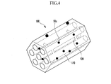
- FIG. 4 is a perspective view of exemplary porous structures according to the present invention.
- various embodiments of the present invention are configured to reduce the wasting of expensive precious metals by minimizing inaccessible regions of the precious metal 15. As such the quantity of the precious metal required for making a catalyst is minimized.
- a porous structure 100 is used so that the dead zone, that is, the inaccessible region of the precious metal 15, can be minimized by improving the diffusion of the exhaust gas.
- porous structures 100 have a plurality of channels and are used as a supporting material of the precious metal.
- the porous structures 100 are made of mesoporous nanoparticles such as MCM or SBA type materials.
- MCM-41 and SBA-15 The most common types of mesoporous nanoparticles are MCM-41 and SBA-15.
- MCM-41 among the MCM series is made by using a micro-colloidal crystal template method and synthesizing well-ordered macroporous silica.
- SBA-15 among the SBA series is made by synthesizing polymer-globular particles using an emulsion polymerization method as an example.
- the synthesized polymer-globular particles are arranged regularly by self-assembling and are blended with a mixture, which is a mother liquid, of a hydrochloric acid solution and a triblock copolymer, and then templates of uniform porous globular particles can be obtained and finally the templates are dried and calcinated.
- the SBA-15 used in various embodiments of the present invention has a mesoporous structure made of silica, and it has pores of 5 to 50nm that are hydrothermally stable by using an amphiphilic block hollow polymer.
- a mesoporous structure made of silica and it has pores of 5 to 50nm that are hydrothermally stable by using an amphiphilic block hollow polymer.
- micro, macro, and meso in this specification are defined according to IUPAC definition (International Union of Pure and Applied Chemistry) as below 2nm, over 50nm, and 2nm to 50nm in pore size respectively.
- IUPAC definition International Union of Pure and Applied Chemistry
- mesoporous silica and mesoporous alumina may be used.
- porous structures 100 will be described in greater detail.
- the porous structures 100 as shown in FIG. 4 , have a plurality of channels 110 and the channels 110 are connected with each other by bridges 120.
- the channels 110 have entrances through which the exhaust gas can pass.
- the bridges 120 are constructed in such a way that small precious metal powders can rarely move through.
- the particles of the precious metal are agglomerated and sintered, so that the required reaction surface is reduced and the decrease of activity can be prevented.
- gaseous reactants can still pass through other entrances of the channel 110 and remain active by preventing the entrance of the pores from being blocked and by preventing the precious metal from becoming an inaccessible state.
- the precious metals are uniformly dispersed as represented by 50c in FIG. 4 . As such, the reaction surface is increased and the activity of the catalyst is enhanced.
- a plurality of channels 110 in various embodiments of the present invention are connected with each other, the gaseous reactants can pass through the entrances of the channels 110, and the diffusion of exhaust gas can be improved thereby.
- the usage of the precious metal can be minimized to an optimal quantity.
Landscapes
- Chemical & Material Sciences (AREA)
- Engineering & Computer Science (AREA)
- Chemical Kinetics & Catalysis (AREA)
- Materials Engineering (AREA)
- Organic Chemistry (AREA)
- Ceramic Engineering (AREA)
- Dispersion Chemistry (AREA)
- Structural Engineering (AREA)
- Combustion & Propulsion (AREA)
- Manufacturing & Machinery (AREA)
- Health & Medical Sciences (AREA)
- Environmental & Geological Engineering (AREA)
- General Engineering & Computer Science (AREA)
- Mechanical Engineering (AREA)
- Biomedical Technology (AREA)
- Toxicology (AREA)
- Analytical Chemistry (AREA)
- General Chemical & Material Sciences (AREA)
- Oil, Petroleum & Natural Gas (AREA)
- Catalysts (AREA)
- Exhaust Gas Treatment By Means Of Catalyst (AREA)
- Exhaust Gas After Treatment (AREA)
Abstract
A catalyst for purifying exhaust gas in vehicles may include a precious metal and porous structures that serve as a supporting material for the precious metal. The porous structures are comprised of a plurality of channels which are connected with each other by a plurality of bridges. The channels may have multiple entrances that allow reactants to pass through and react with the precious metal.
Description
- The present application claims priority of Korean Patent Application Number
10-2010-0120937 - The present invention relates to a catalyst using a precious metal. More particularly, the present invention relates to a highly efficient catalyst using a three-dimensional porous structure as a supporting material for the precious metal in order to prevent an inaccessible region of the precious metal from being generated, and further improve the diffusion of exhaust gas.
- Recently, according to the increasing usage of vehicles and severe traffic, air pollution by exhaust gas is becoming an issue. In order to regulate exhaust gas and enforce the regulations, many countries have established emission standards for pollution substances such as carbon monoxide (CO), hydrocarbon (HC), and nitrogen oxide (NOx) in exhaust gas.
- Usually, catalysts coated with precious metals such as platinum (Pt), palladium (Pd), and rhodium (Rh) are used for removing noxious substances from the exhaust gas of vehicles. These catalysts remove the noxious substances from the exhaust gas and purify the exhaust gas by promoting decomposition of the hydrocarbons, oxidization of the carbon monoxide, and reduction of the nitrogen oxide.
- A catalyst uniformly coated with a precious metal in a supporting material as a purifying catalyst of exhaust gas has been published. In a case of a conventional catalyst for purifying vehicle exhaust gas, the catalyst is manufactured by coating catalytic substances including the expensive precious metal on a supporting material shaped as a honeycomb in order to increase the contact area between the catalyst and the exhaust gas, and thus to increase the reaction area.
- Typically, square cells are used as the unit cells of the honeycomb supporting material. However, as shown in
FIG. 1 , using square cells in a catalyst creates corners where certain amount of catalytic substances accumulates resulting in a thickercatalytic layer 14 in the vicinity of the corners. -
Noxious reactants 16 such as CO, HC, and NOx in the exhaust gas diffuse into the catalytic layer and are then converted into harmless substances in contact with the precious metal (Pt, Pd, and Rh). The arrow inFIG. 1 shows the diffusion of the exhaust gas around a corner. Because the catalytic layer there is thicker, the exhaust gas cannot diffuse into theregion 15 of the precious metal. As such, the catalyst in deep corners becomes an inaccessible region, that is, a dead zone into which the CO, HC, and NOx cannot diffuse. So the precious metal in theinaccessible region 15 cannot participate in reaction. - To solve the above problems, a
hexagonal cell 20 inFIG. 2 was contrived. But the isotropic strength of thehexagonal cell 20 is weaker than that of thesquare cell 10, so fewhexagonal cells 20 are actually used. -
FIG. 3 (A) shows a schematic view of a diffusion path of reactants in a unit cell where 12 refers to a cell wall and can be made of cordierite.FIG. 3(B) and FIG. 3(C) show schematic views of two catalysts where the one shown inFIG. 3(C) is deteriorate. In the past, an amorphous powder was used as a supportingbody 50, so the density of the catalytic layer grew large, the diffusion of the exhaust gas was deteriorated thereby, and an inaccessible region of theprecious metal 15 was generated. In addition, the reaction surface was reduced and pores were covered after the precious metal was sintered (referring to 40 and 50a) or after the precious metal was reacted with sulfur in exhaust gas and was poisoned or otherwise contaminated (referring to 55). Furthermore, inaccessible regions ofprecious metal 50b were generated. - The information disclosed in this Background section is only for enhancement of understanding of the general background of the invention and should not be taken as an acknowledgement or any form of suggestion that this information forms the prior art already known to a person skilled in the art.
- Various aspects of the present invention have been made in an effort to address the problems mentioned above and to provide a highly efficient catalyst by using porous structures as precious metal supporting materials to improve the diffusion of exhaust gas. Various aspects of the present invention provide catalysts to purify the exhaust gas from vehicles. The catalysts use a precious metal and a supporting material that includes the precious metal and has porous structures.
- One aspect of the porous structures according to the present invention is characterized in that they have a plurality of channels and the channels are connected with other channels by bridges.
- Another aspect of the porous structures according to the present invention is characterized in that the structures include channels through which reactant pass thereof.
- Yet other aspects of the porous structures according to the present invention is characterized in that they are made of mesoporous nanoparticles such as MCM or SBA type materials. These mesoporous nanoparticles include mesoporous silica and mesoporous alumina.
- Various aspects of the present invention provide several advantages. First, particles of precious metal can be uniformly spread so that the reaction surface can be increased. Secondly, even if one channel entrance of the structures is blocked by sintering of a supporting material poisoned or contaminated with sulfur, the exhaust gas can pass through other channel entrances so the catalyst can still be reachable and engaging in reaction.
- The methods and apparatuses of the present invention have other features and advantages which will be apparent from or are set forth in more detail in the accompanying drawings, which are incorporated herein, and the following Detailed Description, which together serve to explain certain principles of the present invention.
-
FIG. 1 is a schematic view of a unit cell including a conventional square supporting material. -
FIG. 2 is a schematic view of the unit cell including a conventional hexagonal supporting material. -
FIG. 3(A) shows a schematic view of the diffusion path of reactants in a unit cell wherenumber 12 refers to a cell wall. -
FIG. 3(B) is a schematic view of a catalyst. -
FIG. 3(C) is a schematic view of another catalyst -
FIG. 4 is a perspective view of exemplary porous structures according to the present invention. - It should be understood that the appended drawings are not necessarily to scale, presenting a somewhat simplified representation of various features illustrative of the basic principles of the invention. The specific design features of the present invention as disclosed herein, including, for example, specific dimensions, orientations, locations, and shapes will be determined in part by the particular intended application and use environment.
- In the figures, reference numbers refer to the same or equivalent parts of the present invention throughout the several figures of the drawing.
- Reference will now be made in detail to various embodiments of the present invention(s), examples of which are illustrated in the accompanying drawings and described below. While the invention(s) will be described in conjunction with exemplary embodiments, it will be understood that present description is not intended to limit the invention(s) to those exemplary embodiments. On the contrary, the invention(s) is/are intended to cover not only the exemplary embodiments, but also various alternatives, modifications, equivalents and other embodiments, which may be included within the spirit and scope of the invention as defined by the appended claims.
- Referring to
FIG. 4 , various embodiments of the present invention are configured to reduce the wasting of expensive precious metals by minimizing inaccessible regions of theprecious metal 15. As such the quantity of the precious metal required for making a catalyst is minimized. For this, aporous structure 100 is used so that the dead zone, that is, the inaccessible region of theprecious metal 15, can be minimized by improving the diffusion of the exhaust gas. In various embodiments of the present invention,porous structures 100 have a plurality of channels and are used as a supporting material of the precious metal. Theporous structures 100 are made of mesoporous nanoparticles such as MCM or SBA type materials. - The most common types of mesoporous nanoparticles are MCM-41 and SBA-15. MCM-41 among the MCM series is made by using a micro-colloidal crystal template method and synthesizing well-ordered macroporous silica. SBA-15 among the SBA series is made by synthesizing polymer-globular particles using an emulsion polymerization method as an example. Currently, the synthesized polymer-globular particles are arranged regularly by self-assembling and are blended with a mixture, which is a mother liquid, of a hydrochloric acid solution and a triblock copolymer, and then templates of uniform porous globular particles can be obtained and finally the templates are dried and calcinated. The SBA-15 used in various embodiments of the present invention has a mesoporous structure made of silica, and it has pores of 5 to 50nm that are hydrothermally stable by using an amphiphilic block hollow polymer. For a detailed description of the manufacturing method thereof, one can consult pertinent publications.
- For the purpose of reference, micro, macro, and meso in this specification are defined according to IUPAC definition (International Union of Pure and Applied Chemistry) as below 2nm, over 50nm, and 2nm to 50nm in pore size respectively. In various embodiments of the present invention, mesoporous silica and mesoporous alumina may be used.
- Hereinafter, the
porous structures 100 will be described in greater detail. - The
porous structures 100, as shown inFIG. 4 , have a plurality ofchannels 110 and thechannels 110 are connected with each other bybridges 120. Thechannels 110 have entrances through which the exhaust gas can pass. and thebridges 120 are constructed in such a way that small precious metal powders can rarely move through. - If the catalyst using the
above structures 100 as a supporting material is mounted on a vehicle, the particles of the precious metal are agglomerated and sintered, so that the required reaction surface is reduced and the decrease of activity can be prevented. In addition, even when an entrance of achannel 110 is blocked in sintering a supporting material poisoned or contaminated with sulfur, gaseous reactants can still pass through other entrances of thechannel 110 and remain active by preventing the entrance of the pores from being blocked and by preventing the precious metal from becoming an inaccessible state. Furthermore, the precious metals are uniformly dispersed as represented by 50c inFIG. 4 . As such, the reaction surface is increased and the activity of the catalyst is enhanced. - In other words, a plurality of
channels 110 in various embodiments of the present invention are connected with each other, the gaseous reactants can pass through the entrances of thechannels 110, and the diffusion of exhaust gas can be improved thereby. In addition, the usage of the precious metal can be minimized to an optimal quantity. - The foregoing descriptions of specific exemplary embodiments of the present invention have been presented for purposes of illustration and description. They are not intended to be exhaustive or to limit the invention to the precise forms disclosed, and obviously many modifications and variations are possible in light of the above teachings. The exemplary embodiments were chosen and described in order to explain certain principles of the invention and their practical application, to thereby enable others skilled in the art to make and utilize various exemplary embodiments of the present invention, as well as various alternatives and modifications thereof. It is intended that the scope of the invention be defined by the Claims appended hereto and their equivalents.
Claims (8)
- A catalyst for purifying exhaust gas in a vehicle, the catalyst comprising:a precious metal; andporous structures that serve as a supporting material for the precious metal.
- A catalyst of claim 1, wherein the porous structures comprises:a plurality of channels; anda plurality of bridges that connect the channels with each other.
- A catalyst of claim 2, wherein the channels have multiple entrances through which reactants can pass thereof.
- A catalyst of claim 3, wherein the channels have an entrance on each end of the channels.
- A catalyst of claim 1, wherein the porous structures are made of mesoporous nanoparticles.
- A catalyst of claim 5, wherein the mesoporous nanoparticles are selected from the group of MCM and SBA materials.
- A catalyst of claim 6, wherein the MCM are mesoporous silica or mesoporous alumina.
- A catalyst of claim 6, wherein the SBA materials are mesoporous silica or mesoporous alumina.
Applications Claiming Priority (1)
| Application Number | Priority Date | Filing Date | Title |
|---|---|---|---|
| KR1020100120937A KR101305182B1 (en) | 2010-11-30 | 2010-11-30 | Highly efficient catalyst by using precious metal |
Publications (1)
| Publication Number | Publication Date |
|---|---|
| EP2457654A1 true EP2457654A1 (en) | 2012-05-30 |
Family
ID=44532639
Family Applications (1)
| Application Number | Title | Priority Date | Filing Date |
|---|---|---|---|
| EP11175283A Ceased EP2457654A1 (en) | 2010-11-30 | 2011-07-26 | Highly efficient catalyst using precious metal |
Country Status (5)
| Country | Link |
|---|---|
| US (1) | US8178469B1 (en) |
| EP (1) | EP2457654A1 (en) |
| JP (1) | JP5878700B2 (en) |
| KR (1) | KR101305182B1 (en) |
| CN (1) | CN102476059A (en) |
Families Citing this family (4)
| Publication number | Priority date | Publication date | Assignee | Title |
|---|---|---|---|---|
| US8759241B2 (en) * | 2011-02-25 | 2014-06-24 | General Electric Company | Method for making a catalyst composition |
| KR101776746B1 (en) | 2015-12-04 | 2017-09-08 | 현대자동차 주식회사 | Catalyzed particulate filter |
| JP7295616B2 (en) * | 2017-05-31 | 2023-06-21 | 古河電気工業株式会社 | Catalyst structure for volatile organic substances, method for producing the same, and device for removing volatile organic substances |
| CN110090660B (en) * | 2018-01-30 | 2022-01-04 | 中国石油化工股份有限公司 | Composite material containing Y-type molecular sieve and preparation method thereof |
Citations (7)
| Publication number | Priority date | Publication date | Assignee | Title |
|---|---|---|---|---|
| WO1999030816A1 (en) * | 1997-12-15 | 1999-06-24 | Mobil Oil Corporation | Catalytic reduction of nitrogen oxide emissions with mcm-49 and mcm-56 |
| KR20060083083A (en) * | 2005-01-15 | 2006-07-20 | 현대자동차주식회사 | Method for producing platinum catalyst supported on mesoporous molecular sieve for removing rare nitrogen oxides |
| US20080167178A1 (en) * | 2007-01-09 | 2008-07-10 | Rajashekharam Malyala | High temperature ammonia SCR catalyst and method of using the catalyst |
| US20100166633A1 (en) * | 2008-12-30 | 2010-07-01 | Industrial Technology Research Institute | Catalyst and method for decomposing volatile organic compounds |
| GB2468210A (en) * | 2009-02-26 | 2010-09-01 | Johnson Matthey Plc | Filtering particulate matter from exhaust gas |
| JP2010201398A (en) * | 2009-03-05 | 2010-09-16 | Toyota Motor Corp | Catalyst and method for producing the same |
| KR20100120937A (en) | 2009-05-07 | 2010-11-17 | 최용묵 | Decoration sheet and the manufacturing method of handle cover |
Family Cites Families (29)
| Publication number | Priority date | Publication date | Assignee | Title |
|---|---|---|---|---|
| US4405507A (en) * | 1980-12-22 | 1983-09-20 | Engelhard Corporation | Ozone abatement catalyst having improved durability and low temperature performance |
| US4440874A (en) * | 1982-04-14 | 1984-04-03 | Engelhard Corporation | Catalyst composition and method for its manufacture |
| GB8300554D0 (en) * | 1983-01-10 | 1983-02-09 | Atomic Energy Authority Uk | Catalyst preparation |
| US4509966A (en) * | 1983-05-18 | 1985-04-09 | General Motors Corporation | Wall-flow monolith filter with porous plugs |
| US5378142A (en) * | 1991-04-12 | 1995-01-03 | Engelhard Corporation | Combustion process using catalysts containing binary oxides |
| JPH07308585A (en) | 1994-05-18 | 1995-11-28 | Usui Internatl Ind Co Ltd | Metallic carrier |
| IT1270069B (en) * | 1994-07-06 | 1997-04-28 | Eniricerche Spa | MICRO-MESOPOROUS GEL AND PROCEDURE FOR ITS PREPARATION |
| JP3794035B2 (en) * | 1995-03-27 | 2006-07-05 | マツダ株式会社 | Catalyst for exhaust gas purification of internal combustion engine |
| US6087298A (en) | 1996-05-14 | 2000-07-11 | Engelhard Corporation | Exhaust gas treatment system |
| JP3389851B2 (en) | 1997-01-21 | 2003-03-24 | トヨタ自動車株式会社 | Exhaust gas purification catalyst |
| US6106802A (en) * | 1997-01-31 | 2000-08-22 | Intevep, S.A. | Stable synthetic material and method for preparing same |
| RU2160156C1 (en) * | 1999-12-28 | 2000-12-10 | Закрытое акционерное общество "Катализаторная компания" | High-silica carrier, heterogeneous reaction catalyst and method of preparation thereof |
| JP2002210369A (en) * | 2001-01-19 | 2002-07-30 | Toyota Motor Corp | Exhaust gas purification catalyst and method for producing the same |
| US20020150518A1 (en) * | 2001-04-13 | 2002-10-17 | Brush Dagan W. | Gas treatment device |
| JP2002320850A (en) | 2001-04-25 | 2002-11-05 | Toyota Motor Corp | Catalyst and exhaust gas purification device using the catalyst |
| JP3794288B2 (en) | 2001-06-25 | 2006-07-05 | 日産自動車株式会社 | Exhaust gas purification catalyst and method for producing the same |
| US6958309B2 (en) * | 2002-08-01 | 2005-10-25 | Conocophillips Company | Hydrothermal pretreatment for increasing average pore size in a catalyst support |
| JP5031168B2 (en) * | 2002-08-22 | 2012-09-19 | 株式会社デンソー | Catalyst body |
| KR100527970B1 (en) * | 2003-02-17 | 2005-11-09 | 현대자동차주식회사 | Circular cell ceramic honeycomb substrate for automobile |
| CA2555506C (en) | 2004-02-11 | 2012-05-29 | Umicore Ag & Co. Kg | Exhaust gas cleaning catalyst with an axially varying precious metal concentration and processes for making the catalyst |
| US7374729B2 (en) | 2004-03-30 | 2008-05-20 | Basf Catalysts Llc | Exhaust gas treatment catalyst |
| US20050249645A1 (en) * | 2004-05-05 | 2005-11-10 | Eaton Corporation | Catalyst and adsorbant bed configurations suitable for mobile applications |
| US7935653B2 (en) * | 2004-06-11 | 2011-05-03 | Kabushiki Kaisha Toyota Chuo Kenkyusho | Metal oxide nanoporous material, coating composition to obtain the same, and methods of manufacturing them |
| GB0515276D0 (en) * | 2005-07-26 | 2005-08-31 | Accentus Plc | Catalyst |
| JP4788497B2 (en) | 2005-12-27 | 2011-10-05 | 株式会社デンソー | Hex honeycomb structure |
| JP2008023428A (en) * | 2006-07-19 | 2008-02-07 | Mazda Motor Corp | Exhaust gas purification catalyst |
| US20080020922A1 (en) * | 2006-07-21 | 2008-01-24 | Li Cheng G | Zone catalyzed soot filter |
| CN101306382B (en) * | 2007-05-16 | 2011-05-18 | 中国石油化工股份有限公司 | Catalyst for alkyl aromatics isomerization |
| CN101342495B (en) * | 2008-04-22 | 2010-09-29 | 深圳大学 | A catalyst preparation method and its performance testing device |
-
2010
- 2010-11-30 KR KR1020100120937A patent/KR101305182B1/en not_active Expired - Fee Related
-
2011
- 2011-06-29 JP JP2011143814A patent/JP5878700B2/en not_active Expired - Fee Related
- 2011-07-22 US US13/188,880 patent/US8178469B1/en not_active Expired - Fee Related
- 2011-07-26 EP EP11175283A patent/EP2457654A1/en not_active Ceased
- 2011-08-03 CN CN2011102255124A patent/CN102476059A/en active Pending
Patent Citations (7)
| Publication number | Priority date | Publication date | Assignee | Title |
|---|---|---|---|---|
| WO1999030816A1 (en) * | 1997-12-15 | 1999-06-24 | Mobil Oil Corporation | Catalytic reduction of nitrogen oxide emissions with mcm-49 and mcm-56 |
| KR20060083083A (en) * | 2005-01-15 | 2006-07-20 | 현대자동차주식회사 | Method for producing platinum catalyst supported on mesoporous molecular sieve for removing rare nitrogen oxides |
| US20080167178A1 (en) * | 2007-01-09 | 2008-07-10 | Rajashekharam Malyala | High temperature ammonia SCR catalyst and method of using the catalyst |
| US20100166633A1 (en) * | 2008-12-30 | 2010-07-01 | Industrial Technology Research Institute | Catalyst and method for decomposing volatile organic compounds |
| GB2468210A (en) * | 2009-02-26 | 2010-09-01 | Johnson Matthey Plc | Filtering particulate matter from exhaust gas |
| JP2010201398A (en) * | 2009-03-05 | 2010-09-16 | Toyota Motor Corp | Catalyst and method for producing the same |
| KR20100120937A (en) | 2009-05-07 | 2010-11-17 | 최용묵 | Decoration sheet and the manufacturing method of handle cover |
Also Published As
| Publication number | Publication date |
|---|---|
| US8178469B1 (en) | 2012-05-15 |
| US20120135859A1 (en) | 2012-05-31 |
| CN102476059A (en) | 2012-05-30 |
| KR20120059266A (en) | 2012-06-08 |
| JP2012115824A (en) | 2012-06-21 |
| KR101305182B1 (en) | 2013-09-12 |
| JP5878700B2 (en) | 2016-03-08 |
Similar Documents
| Publication | Publication Date | Title |
|---|---|---|
| US8080494B2 (en) | Catalyst, exhaust gas purifying catalyst, and method of producing the catalyst | |
| CN101528326B (en) | Vanadium-free catalyst for selective catalytic reduction and its preparation method | |
| CN104812486B (en) | Ammonia oxidation catalyst | |
| EP1955765B1 (en) | Process for producing a catalyst for exhaust-gas purification | |
| US7601670B2 (en) | Catalyst powder, exhaust gas purifying catalyst, and method of producing the catalyst powder | |
| CN103889570B (en) | Exhaust gas purification catalyst | |
| US9358534B2 (en) | Catalyst, catalytic converter, and method for the production thereof | |
| EP3254757A1 (en) | Exhaust gas purification catalyst | |
| JP6539666B2 (en) | Exhaust gas purification catalyst | |
| JP2022527152A (en) | Layered three-metal catalyst article and method for manufacturing the catalyst article | |
| CN114377694B (en) | Exhaust purification device | |
| JP2007283289A (en) | Catalytic converter and manufacturing method of catalytic converter | |
| JP2006043654A (en) | Exhaust gas purification catalyst and method for producing the same | |
| CN102365124A (en) | Aging Resistant Catalyst for Oxidation of NO in Exhaust Streams to NO2 | |
| US8178469B1 (en) | Highly efficient catalyst using precious metal | |
| EP2078562A1 (en) | Exhaust gas purifying catalyst | |
| US20160288052A1 (en) | Exhaust gas purifying catalyst | |
| CN114109568B (en) | Exhaust gas purifying device | |
| JP4063807B2 (en) | Exhaust gas purification catalyst | |
| CN113905819B (en) | Exhaust gas purification catalyst and exhaust gas purification system using the same | |
| JPWO2011052676A1 (en) | Exhaust gas purification device for internal combustion engine | |
| JP2006224032A (en) | Exhaust gas purification catalyst | |
| JP2021104474A (en) | Exhaust gas purification catalyst | |
| JP2008006353A (en) | CO oxidation method | |
| CN1986035A (en) | A method for purifying automobile exhaust |
Legal Events
| Date | Code | Title | Description |
|---|---|---|---|
| PUAI | Public reference made under article 153(3) epc to a published international application that has entered the european phase |
Free format text: ORIGINAL CODE: 0009012 |
|
| AK | Designated contracting states |
Kind code of ref document: A1 Designated state(s): AL AT BE BG CH CY CZ DE DK EE ES FI FR GB GR HR HU IE IS IT LI LT LU LV MC MK MT NL NO PL PT RO RS SE SI SK SM TR |
|
| AX | Request for extension of the european patent |
Extension state: BA ME |
|
| 17P | Request for examination filed |
Effective date: 20121108 |
|
| 17Q | First examination report despatched |
Effective date: 20150331 |
|
| STAA | Information on the status of an ep patent application or granted ep patent |
Free format text: STATUS: THE APPLICATION HAS BEEN REFUSED |
|
| 18R | Application refused |
Effective date: 20180216 |