EP2457544A1 - Improved hyperextension orthopaedic corset - Google Patents
Improved hyperextension orthopaedic corset Download PDFInfo
- Publication number
- EP2457544A1 EP2457544A1 EP11190484A EP11190484A EP2457544A1 EP 2457544 A1 EP2457544 A1 EP 2457544A1 EP 11190484 A EP11190484 A EP 11190484A EP 11190484 A EP11190484 A EP 11190484A EP 2457544 A1 EP2457544 A1 EP 2457544A1
- Authority
- EP
- European Patent Office
- Prior art keywords
- corset
- hyperextension
- pairs
- lateral uprights
- orthopaedic
- Prior art date
- Legal status (The legal status is an assumption and is not a legal conclusion. Google has not performed a legal analysis and makes no representation as to the accuracy of the status listed.)
- Granted
Links
Images


Classifications
-
- A—HUMAN NECESSITIES
- A61—MEDICAL OR VETERINARY SCIENCE; HYGIENE
- A61F—FILTERS IMPLANTABLE INTO BLOOD VESSELS; PROSTHESES; DEVICES PROVIDING PATENCY TO, OR PREVENTING COLLAPSING OF, TUBULAR STRUCTURES OF THE BODY, e.g. STENTS; ORTHOPAEDIC, NURSING OR CONTRACEPTIVE DEVICES; FOMENTATION; TREATMENT OR PROTECTION OF EYES OR EARS; BANDAGES, DRESSINGS OR ABSORBENT PADS; FIRST-AID KITS
- A61F5/00—Orthopaedic methods or devices for non-surgical treatment of bones or joints; Nursing devices ; Anti-rape devices
- A61F5/01—Orthopaedic devices, e.g. long-term immobilising or pressure directing devices for treating broken or deformed bones such as splints, casts or braces
- A61F5/02—Orthopaedic corsets
- A61F5/024—Orthopaedic corsets having pressure pads connected in a frame for reduction or correction of the curvature of the spine
-
- A—HUMAN NECESSITIES
- A61—MEDICAL OR VETERINARY SCIENCE; HYGIENE
- A61F—FILTERS IMPLANTABLE INTO BLOOD VESSELS; PROSTHESES; DEVICES PROVIDING PATENCY TO, OR PREVENTING COLLAPSING OF, TUBULAR STRUCTURES OF THE BODY, e.g. STENTS; ORTHOPAEDIC, NURSING OR CONTRACEPTIVE DEVICES; FOMENTATION; TREATMENT OR PROTECTION OF EYES OR EARS; BANDAGES, DRESSINGS OR ABSORBENT PADS; FIRST-AID KITS
- A61F5/00—Orthopaedic methods or devices for non-surgical treatment of bones or joints; Nursing devices ; Anti-rape devices
- A61F5/01—Orthopaedic devices, e.g. long-term immobilising or pressure directing devices for treating broken or deformed bones such as splints, casts or braces
- A61F5/30—Pressure pads
Definitions
- the present invention refers to an improved hyperextension orthopaedic corset, that can be used for the treatment of mildly serious and serious dorso-lumbar pathologies.
- the pathologies of interest are the results from traumas, such as spinal fractures, tumour pathologies, which can lead to spinal metastasis with consequent increased porosity of the affected bone structure, or osteoporosis due to aging, which can lead to vertebral collapses associated with compression of the nerve endings.
- the hyperextension orthopaedic corset consists of a frame structure in light aluminium alloy which, once worn on the trunk, offers two thrust points in the front part, that can be identified in the chest area (breastbone) and on the pelvis, and a thrust point in the rear part (indicatively at the dorso-lumbar transition), created with a rigid belt constrained to the aluminium structure.
- the supports points on the chest and on the lumbar area consist of stuffed plates, which ensure the advantageous distribution of the pressure on a more extended body surface.
- Hyperextension orthopaedic corsets are normally available in different sizes, but must in any case be perfectly adjusted and adapted on the basis of the morphology of each single patient.
- the adjustments may concern the width of the chest at the height of the breastbone, the height of the trunk and the inclination of the pelvic strap.
- the hyperextension corset in addition to carrying out the adjustments of the frame structure through screws, it is necessary to arrange the lumbar plate pulling tight the rear belt through a system of buckles, which do not always allow the orthopaedics technician to perform a stable and precise adjustment.
- the pelvic strap which in some cases must vary its actual relative position with respect to the frame structure, for example to allow the patient to sit while wearing the corset, is adjusted through a screw system. It is therefore necessary for the orthopaedics technician to have considerable manual ability in order to position and lock the screws, bearing also in mind that the patient generally has limited mobility and can also suffer pain during the adjustment steps. The risk of losing or damaging the adjustment screws can also be high.
- misalignments can occur between the components of the hyperextension corset, especially during the adjustment steps of the relative position of the pelvic strap with respect to the frame structure. These misalignments can lead to deformations on the components of the hyperextension corset which, although of limited extent, can jeopardise the functionality and the stability of the hyperextension corset itself, as well as the level of comfort of the patient.
- the purpose of the present invention is therefore that of realizing an improved hyperextension orthopaedic corset which can be precisely and safely adjusted, combining the needs both of the patient and of the orthopaedics technician.
- Another purpose of the invention is that of realizing an improved hyperextension orthopaedic corset in which deformations occurred during the adjustment steps of the various components are avoided, or in any case minimised.
- a further purpose of the present invention is that of realizing an improved hyperextension orthopaedic corset that is particularly simple and functional, with low costs.
- an improved hyperextension orthopaedic corset is shown according to the present invention, wholly indicated with reference number 10.
- the corset 10 consists of a frame structure in light aluminium alloy, provided with relative movements for adjusting the thoracic width, the height of the trunk and the positioning on the pelvis.
- Accessories which form stuffed surfaces at the contact points with the trunk of the patient, and a system of belts for tensioning the corset 10 once it is worn are applied to the frame structure, through suitable joint elements, as better specified below.
- the frame structure consists of rods developing substantially horizontally, arranged at the breastbone and at the pelvis, spaced by substantially vertical lateral uprights.
- the frame structure comprises, at the top and in a front position with reference to the body of the user, a pair of sternal rods 12 which have a rectilinear portion 14 and a curved portion 16, so as to adapt to the shape of the chest.
- the end portions of the curved portions 16 comprise suitable means, not illustrated for the sake of simplicity since they are of the known type at the state of the art, for coupling with adjustable inclination with the lateral uprights 18.
- Each rectilinear portion 14 of the sternal rods 12 is provided with a rectangular window 20 close to the ends and with a groove 22 which is placed on the remaining rectilinear portion.
- the two rectilinear portions 14 are mounted on top of each other in a position symmetrical with respect to a sagittal plane A, so as to permit a translation relative movement.
- the two sternal rods 12 are kept coupled by constraining elements, which consist of two adjustment clamps 24 which engage each with the rectangular window 20 and with the groove 22, simultaneously.
- the adjustment clamps 24 are of the known type at the state of the art and shall not therefore be described in detail.
- Two upper lateral uprights 26, right and left, are applied to the sternal rods 12 preferably but not necessarily with an angular adjustment which can be snap adjusted according to a reasonable number of positions.
- the connection between the sternal rods 12 and the upper lateral uprights 26 is carried out by means of threaded fixing means which also permits the aforementioned angular adjustment.
- Each upper lateral upright 26 is also coupled, in a manner such as to permit the height adjustment, with a respective lower lateral upright 28, so as to form the entire lateral upright 18 of the corset 10.
- Each upper pair of lateral uprights 26 and lower pair of lateral uprights 28 is kept in contact through threaded constraining means, which engage into proper holes or grooves provided in the upper 26 and lower 28 lateral uprights themselves. Such constraining elements can thus be blocked in position, once the correct height adjustment of the entire lateral upright 18 has been obtained, through a suitable locking tool.
- the lower lateral uprights 28 end with a lower curved portion 30, which follows the widening of the pelvis of the user and ends in turn with a joining element 32 which is articulated to a pelvic strap 34, which constitutes the lower horizontal rod for connecting the lateral uprights 18.
- the tensioning system comprises a rear belt 36 whereon a lumbar plate 38 is inserted.
- a lumbar plate 38 suitably reinforced and stuffed, constitutes the rear thrust point of the corset 10.
- the rear belt 36 is constrainable, at its opposite ends, to the lateral uprights 18 and comprises toothed means for step-by-step adjusting the length of the rear belt 36 itself and for tensioning the corset 10.
- a first end 36a of the rear belt 36 is made integral with a closing lever 40, constrained to one of the lateral uprights 18, whereas on the second end 36b of such a rear belt 36 a toothed belt 42 is obtained selectively engageable with one or more teeth 44 obtained on a hooking means 46, to the opposite lateral upright 18.
- the hooking means 46 is provided with a tapered hole 48, so as to allow inserting into its inside and blocking in position a projecting pin element 50 integral with one of the lateral uprights 18, hence realizing a dismountable connection of the rear belt 36 to the frame structure of the corset 10.
- the tooth 44 of the hooking means 46 is provided with elastic elements 52 actuatable so as to obtain a disengaging movement between such a tooth 44 and the teeth of the toothed belt 42 and, thus, the relative sliding between the hooking means 46 and the toothed belt 42.
- the elastic elements 52 preferably consist of coil springs.
- the pelvic strap 34 consists of a metal core covered by a padding 58 and curved according to an anatomical shape so as to adapt to the pelvis of the user of the corset 10.
- a threaded pin 60 is applied, around which the plate 62 can rotate.
- the plate 62 is in turn rigidly constrained to the ends of the pelvic strap 34 through an anchoring system realized, for example, through screws.
- a torsion spring 64 is applied, constrained to the pelvic strap 34 on one side and to the curved end portion 30 of the lower lateral upright 28 on the other side.
- the pelvic strap 34 is provided with the possibility of oscillating with respect to the lateral uprights 18, so as to be capable of complying with the movements of the user of the corset 10. For example, when the user sits down, the pelvic strap 34 can rotate upwards so as not to hit against the legs and thus avoid the translation of the entire corset 10.
- At least one extractable adjusting block 66 is provided, capable of cooperating with a pin 68 integral with the curved end portion 30 of the lower lateral upright 28 and with the plate 62.
- the adjusting block 66 is provided with one or more slots 70 for engaging with the pin 68 and with one or more grooved guides 72 for engaging with corresponding guides 74 obtained in the plate 62.
- the inner core of the pelvic strap 34 can be manufactured with a material with variable elasticity. More precisely, the elasticity of the inner core is greater at the ends of the pelvic strap 34, so as to be able to absorb possible deformations caused during the adjusting steps of the corset 10.
- the inner core of the pelvic strap 34 can be realized by coupling, for example through rivets 76, two metal materials having different elasticity.
- the metal material with greater elasticity with respect to the metal material used for the central portion of the pelvic strap 34 will thus be arranged at the ends of the pelvic strap 34.
- Respective stuffed lateral plates 80 are, on the other hand, applied to the lateral uprights 18, said lateral plates 80 also being anatomical shaped so as to best adapt to the hips and protect them from contact with the lateral uprights 18 themselves.
- Both the sternal plate 78 and the lateral plates 80 are provided with suitable means for fastening, preferably buttons, to the respective components of the aluminium structure.
- the operations for applying the hyperextension corset 10 consist in buttoning the hooking means 46 of the rear belt 36 to the projecting pin element 50, so that such a rear belt 36 be adherent to the body, but not tight, and that the closing lever 40 be in the open position. After having suitably adjusted the toothed belt 42 on the relative hooking means 46, by actuating the closing lever 40 it is finally possible to tighten the rear belt 36 and to obtain the correct application of the hyperextension corset 10.
- the pelvic strap 34 can, on the other hand, remain free to oscillate, counteracting the action of the torsion spring 64, or it can be blocked according to a predefined position with respect to the lateral uprights 18, as described previously.
- the orthopaedics technician will be able to protect all internal components of the articulated joining element 32 from tampering, through the aforementioned plastic cover, kept in position by the relative screw.
- the improved hyperextension orthopaedic corset of the present invention thus conceived can in any case undergo numerous modifications and variants, all covered by the same inventive concept; moreover, all the details can be replaced by technically equivalent elements.
- the materials used, as well as shapes and sizes, may be any according to the technical needs.
Landscapes
- Health & Medical Sciences (AREA)
- Nursing (AREA)
- Orthopedic Medicine & Surgery (AREA)
- Engineering & Computer Science (AREA)
- Biomedical Technology (AREA)
- Heart & Thoracic Surgery (AREA)
- Vascular Medicine (AREA)
- Life Sciences & Earth Sciences (AREA)
- Animal Behavior & Ethology (AREA)
- General Health & Medical Sciences (AREA)
- Public Health (AREA)
- Veterinary Medicine (AREA)
- Orthopedics, Nursing, And Contraception (AREA)
Abstract
Description
- The present invention refers to an improved hyperextension orthopaedic corset, that can be used for the treatment of mildly serious and serious dorso-lumbar pathologies.
- Numerous pathologies or results from trauma require the stabilization of the spinal column and an anti-gravitational action on the rachis, which permits to lighten it from the load of the upper part of the trunk that normally, by gravity, indeed discharges along the rachis.
- The pathologies of interest are the results from traumas, such as spinal fractures, tumour pathologies, which can lead to spinal metastasis with consequent increased porosity of the affected bone structure, or osteoporosis due to aging, which can lead to vertebral collapses associated with compression of the nerve endings.
- Currently, the needs for immobilisation and lightening of the load on the rachis are solved by using a so-called hyperextension corset, which the patient must always wear when he is in the erect position. In such a circumstance, indeed, the load of the upper part of the trunk entirely weighs down upon the spinal column.
- The hyperextension orthopaedic corset consists of a frame structure in light aluminium alloy which, once worn on the trunk, offers two thrust points in the front part, that can be identified in the chest area (breastbone) and on the pelvis, and a thrust point in the rear part (indicatively at the dorso-lumbar transition), created with a rigid belt constrained to the aluminium structure.
- In order to improve the comfort of patients, the supports points on the chest and on the lumbar area consist of stuffed plates, which ensure the advantageous distribution of the pressure on a more extended body surface.
- Hyperextension orthopaedic corsets are normally available in different sizes, but must in any case be perfectly adjusted and adapted on the basis of the morphology of each single patient. The adjustments may concern the width of the chest at the height of the breastbone, the height of the trunk and the inclination of the pelvic strap. In order to wear the hyperextension corset, in addition to carrying out the adjustments of the frame structure through screws, it is necessary to arrange the lumbar plate pulling tight the rear belt through a system of buckles, which do not always allow the orthopaedics technician to perform a stable and precise adjustment.
- Also the pelvic strap, which in some cases must vary its actual relative position with respect to the frame structure, for example to allow the patient to sit while wearing the corset, is adjusted through a screw system. It is therefore necessary for the orthopaedics technician to have considerable manual ability in order to position and lock the screws, bearing also in mind that the patient generally has limited mobility and can also suffer pain during the adjustment steps. The risk of losing or damaging the adjustment screws can also be high.
- Finally, with the current adjustment systems misalignments can occur between the components of the hyperextension corset, especially during the adjustment steps of the relative position of the pelvic strap with respect to the frame structure. These misalignments can lead to deformations on the components of the hyperextension corset which, although of limited extent, can jeopardise the functionality and the stability of the hyperextension corset itself, as well as the level of comfort of the patient.
- The purpose of the present invention is therefore that of realizing an improved hyperextension orthopaedic corset which can be precisely and safely adjusted, combining the needs both of the patient and of the orthopaedics technician.
- Another purpose of the invention is that of realizing an improved hyperextension orthopaedic corset in which deformations occurred during the adjustment steps of the various components are avoided, or in any case minimised.
- A further purpose of the present invention is that of realizing an improved hyperextension orthopaedic corset that is particularly simple and functional, with low costs.
- These purposes according to the present invention are achieved by realizing an improved hyperextension orthopaedic corset as outlined in claim 1.
- Further characteristics of the invention are highlighted by the dependent claims, which are an integrating part of the present description.
- The characteristics and advantages of an improved hyperextension orthopaedic corset according to the present invention shall become clearer from the following description, exemplifying and not limiting, with reference to the attached schematic drawings, in wherein:
-
figure 1 is a front view of a hyperextension orthopaedic corset being worn; -
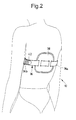
figure 2 is a rear view of the hyperextension orthopaedic corset offigure 1 ; -
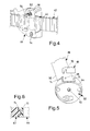
figure 3 is an exploded view of some components of the hyperextension orthopaedic corset offigure 1 ; -
figure 4 is another view of the components of the hyperextension orthopaedic corset shown infigure 3 ; -
figure 5 is an exploded view of further components of the hyperextension orthopaedic corset offigure 1 ; and -
figure 6 is an enlarged detailed view of the components of the hyperextension orthopaedic corset shown infigure 5 . - With reference to the figures, an improved hyperextension orthopaedic corset is shown according to the present invention, wholly indicated with
reference number 10. Thecorset 10 consists of a frame structure in light aluminium alloy, provided with relative movements for adjusting the thoracic width, the height of the trunk and the positioning on the pelvis. Accessories which form stuffed surfaces at the contact points with the trunk of the patient, and a system of belts for tensioning thecorset 10 once it is worn are applied to the frame structure, through suitable joint elements, as better specified below. - The frame structure consists of rods developing substantially horizontally, arranged at the breastbone and at the pelvis, spaced by substantially vertical lateral uprights. In detail, the frame structure comprises, at the top and in a front position with reference to the body of the user, a pair of
sternal rods 12 which have a rectilinear portion 14 and acurved portion 16, so as to adapt to the shape of the chest. The end portions of thecurved portions 16 comprise suitable means, not illustrated for the sake of simplicity since they are of the known type at the state of the art, for coupling with adjustable inclination with thelateral uprights 18. - Each rectilinear portion 14 of the
sternal rods 12 is provided with arectangular window 20 close to the ends and with agroove 22 which is placed on the remaining rectilinear portion. The two rectilinear portions 14 are mounted on top of each other in a position symmetrical with respect to a sagittal plane A, so as to permit a translation relative movement. - The two
sternal rods 12 are kept coupled by constraining elements, which consist of twoadjustment clamps 24 which engage each with therectangular window 20 and with thegroove 22, simultaneously. Theadjustment clamps 24 are of the known type at the state of the art and shall not therefore be described in detail. - Two upper
lateral uprights 26, right and left, are applied to thesternal rods 12 preferably but not necessarily with an angular adjustment which can be snap adjusted according to a reasonable number of positions. The connection between thesternal rods 12 and the upperlateral uprights 26 is carried out by means of threaded fixing means which also permits the aforementioned angular adjustment. - Each upper lateral upright 26 is also coupled, in a manner such as to permit the height adjustment, with a respective lower lateral upright 28, so as to form the entire lateral upright 18 of the
corset 10. Each upper pair oflateral uprights 26 and lower pair oflateral uprights 28 is kept in contact through threaded constraining means, which engage into proper holes or grooves provided in the upper 26 and lower 28 lateral uprights themselves. Such constraining elements can thus be blocked in position, once the correct height adjustment of the entire lateral upright 18 has been obtained, through a suitable locking tool. - The lower
lateral uprights 28 end with a lowercurved portion 30, which follows the widening of the pelvis of the user and ends in turn with a joiningelement 32 which is articulated to apelvic strap 34, which constitutes the lower horizontal rod for connecting thelateral uprights 18. - The tensioning system comprises a
rear belt 36 whereon alumbar plate 38 is inserted. Such alumbar plate 38, suitably reinforced and stuffed, constitutes the rear thrust point of thecorset 10. Therear belt 36 is constrainable, at its opposite ends, to thelateral uprights 18 and comprises toothed means for step-by-step adjusting the length of therear belt 36 itself and for tensioning thecorset 10. - In detail, a
first end 36a of therear belt 36 is made integral with aclosing lever 40, constrained to one of thelateral uprights 18, whereas on thesecond end 36b of such arear belt 36 atoothed belt 42 is obtained selectively engageable with one ormore teeth 44 obtained on ahooking means 46, to the opposite lateral upright 18. Thehooking means 46 is provided with atapered hole 48, so as to allow inserting into its inside and blocking in position a projectingpin element 50 integral with one of thelateral uprights 18, hence realizing a dismountable connection of therear belt 36 to the frame structure of thecorset 10. - The
tooth 44 of thehooking means 46 is provided withelastic elements 52 actuatable so as to obtain a disengaging movement between such atooth 44 and the teeth of thetoothed belt 42 and, thus, the relative sliding between thehooking means 46 and thetoothed belt 42. Theelastic elements 52 preferably consist of coil springs. Once the tension of thebelt 36 has been correctly adjusted, through the aforementioned relative sliding between thehooking means 46 and thetoothed belt 42 obtained on thesecond end 36b of such abelt 36, it is possible to block the movement of thetooth 44 through threaded tightening means 54 which compress theelastic elements 52. Preferably, the threaded tightening means 54 consist of screws which insert into therespective coil springs 52 and engage within threadedholes 56 obtained in thehooking means 46. - The
pelvic strap 34 consists of a metal core covered by apadding 58 and curved according to an anatomical shape so as to adapt to the pelvis of the user of thecorset 10. On thecurved end portion 30 of the lower lateral upright a threadedpin 60 is applied, around which theplate 62 can rotate. Theplate 62 is in turn rigidly constrained to the ends of thepelvic strap 34 through an anchoring system realized, for example, through screws. On the articulated joining element 32 atorsion spring 64 is applied, constrained to thepelvic strap 34 on one side and to thecurved end portion 30 of the lower lateral upright 28 on the other side. - The
pelvic strap 34 is provided with the possibility of oscillating with respect to thelateral uprights 18, so as to be capable of complying with the movements of the user of thecorset 10. For example, when the user sits down, thepelvic strap 34 can rotate upwards so as not to hit against the legs and thus avoid the translation of theentire corset 10. - In order to block the oscillation of the
pelvic strap 34, as well as to arrange it according to a predefined angle with respect to thelateral uprights 18, at least oneextractable adjusting block 66 is provided, capable of cooperating with apin 68 integral with thecurved end portion 30 of the lower lateral upright 28 and with theplate 62. In detail, the adjustingblock 66 is provided with one ormore slots 70 for engaging with thepin 68 and with one or moregrooved guides 72 for engaging withcorresponding guides 74 obtained in theplate 62. Once it has been inserted into theplate 62, the adjustingblock 66 is thus capable of blocking the relative rotation of thepelvic strap 34 with respect to thelateral uprights 18 of thecorset 10. Theplate 62 and the elements correlated with it, in particular thetorsion spring 64 and the adjustingblock 66, are protected by a plastic cover kept in position by a screw. - Advantageously, the inner core of the
pelvic strap 34 can be manufactured with a material with variable elasticity. More precisely, the elasticity of the inner core is greater at the ends of thepelvic strap 34, so as to be able to absorb possible deformations caused during the adjusting steps of thecorset 10. - Alternatively or in addition, the inner core of the
pelvic strap 34 can be realized by coupling, for example throughrivets 76, two metal materials having different elasticity. The metal material with greater elasticity with respect to the metal material used for the central portion of thepelvic strap 34 will thus be arranged at the ends of thepelvic strap 34. - A
plate 78 for supporting the breastbone, preferably in aluminium, stuffed and suitably shaped with an anatomical shape, which is capable of an oscillating movement for adapting to the inclination of the wall of the breastbone, is applied to thesternal rods 12. - Respective stuffed
lateral plates 80 are, on the other hand, applied to thelateral uprights 18, saidlateral plates 80 also being anatomical shaped so as to best adapt to the hips and protect them from contact with thelateral uprights 18 themselves. Both thesternal plate 78 and thelateral plates 80 are provided with suitable means for fastening, preferably buttons, to the respective components of the aluminium structure. - The operations for applying the
hyperextension corset 10 consist in buttoning the hooking means 46 of therear belt 36 to the projectingpin element 50, so that such arear belt 36 be adherent to the body, but not tight, and that the closinglever 40 be in the open position. After having suitably adjusted thetoothed belt 42 on the relative hookingmeans 46, by actuating the closinglever 40 it is finally possible to tighten therear belt 36 and to obtain the correct application of thehyperextension corset 10. - The tightening of the
screws 54, along with the actuation of a safety mechanism (which is not shown) foreseen on the closinglever 40, prevents therear belt 36 from accidentally loosening and therefore a possible complete release of thecorset 10, which would cause a sudden collapsing of the trunk. - All further adjustments of the
corset 10, amongst which for example the adjustment of thesternal rods 12 based upon the width of the chest and the adjustment of thelateral uprights 18 based upon the height of the trunk of the user, are carried out in a manner that is per se known by a specialised orthopaedics technician. - The
pelvic strap 34 can, on the other hand, remain free to oscillate, counteracting the action of thetorsion spring 64, or it can be blocked according to a predefined position with respect to thelateral uprights 18, as described previously. - Also in this case, in order to avoid undesired movements of the
pelvic strap 34 with respect to thelateral uprights 18, the orthopaedics technician will be able to protect all internal components of the articulated joiningelement 32 from tampering, through the aforementioned plastic cover, kept in position by the relative screw. - It has thus been seen that the improved hyperextension orthopaedic corset according to the present invention achieves the purposes previously highlighted.
- The improved hyperextension orthopaedic corset of the present invention thus conceived can in any case undergo numerous modifications and variants, all covered by the same inventive concept; moreover, all the details can be replaced by technically equivalent elements. In practice the materials used, as well as shapes and sizes, may be any according to the technical needs.
- The scope of protection of the invention is thus defined by the attached claims.
Claims (10)
- Hyperextension orthopaedic corset (10) constituted by a frame structure consisting of a pair of upper sternal rods (12) developping substantially horizontally, two pairs of lateral uprights (18) developping substantially vertically and a lower pelvic strap (34), substantially horizontal, for the connection between said pairs of lateral uprights (18), wherein said pair of sternal rods (12) and said pairs of lateral uprights (18) are provided with adjustable translation relative movement and are preferably provided with mutual connecting means with adjustable inclination, the corset (10) further comprising a rear belt (36) for the application to the trunk, constrainable at its opposite ends (36a, 36b) to said pairs of lateral uprights (18), and a plurality of accessories (38, 78, 80), adjustably constrainable to the frame structure, which form stuffed surfaces at the contact points of the corset (10) with the trunk, characterised in that said rear belt (36) comprises toothed means (42, 46) for step-by-step adjusting of length of said rear belt (36) and for tensioning the corset (10).
- Hyperextension orthopaedic corset (10) according to claim 1, characterised in that said toothed means (42, 46) comprise a toothed belt (42), obtained on one of the two ends (36b) of the rear belt (36), and a hooking means (46), provided with at least one tooth (44) selectively engageable with said toothed belt (42) and suitable for hooking said rear belt (36) to one of said pairs of lateral uprights (18).
- Hyperextension orthopaedic corset (10) according to claim 2, characterised in that said hooking means (46) is provided with a tapered hole (48), so as to allow inserting into its inside and blocking in position a projecting pin element (50) integral with one of said pairs of lateral uprights (18), hence realizing a dismountable connection of the rear belt (36) to the frame structure of the corset (10).
- Hyperextension orthopaedic corset (10) according to claim 2 or 3, characterised in that the tooth (44) of said hooking means (46) is provided with elastic elements (52) actuatable to obtain a disengagement movement between said tooth (44) and the teeth of the toothed belt (42) and, thus, a relative sliding between said hooking means (46) and said toothed belt (42).
- Hyperextension orthopaedic corset (10) according to claim 4, characterised in that said hooking means (46) comprises threaded tightening means (54) capable of compressing said elastic elements (52) to block the movement of the tooth (44).
- Hyperextension orthopaedic corset (10) according to any one of the claims from 1 to 5, characterised in that said pairs of lateral uprights (18) are constrained to the lower pelvic strap (34), at its ends, through a rotary joining element (32) comprising a pin (60) whereon a plate (62) provided with a torsion spring (64) rotates, constrained to the lower pelvic strap (34) on one side and to each of said pairs of lateral uprights (18) on the other side, to allow the oscillation of said lower pelvic strap (34) with respect to said pairs of lateral uprights (18).
- Hyperextension orthopaedic corset (10) according to claim 6, characterised in that said rotary joining element (32) comprises at least one extractable adjusting block (66), capable of cooperating with a pin (68) integral with the lower portion (30) of each of said pairs of lateral uprights (18) and with the plate (62) for blocking the oscillation of the lower pelvic strap (34), as well as for arranging said lower pelvic strap (34) according to a predefined angle with respect to said pairs of lateral uprights (18).
- Hyperextension orthopaedic corset (10) according to claim 7, characterised in that said adjusting block (66) is provided with one or more slots (70) for engaging with said pin (68) and with one or more grooved guides (72) for engaging with corresponding guides (74) obtained in the plate (62) so that, once inserted into said plate (62), the adjusting block (66) is capable of blocking the relative rotation of the lower pelvic strap (34) with respect to said pairs of lateral uprights (18).
- Hyperextension orthopaedic corset (10) according to any of the preceding claims, characterised in that the lower pelvic strap (34) is provided with an inner core manufactured with a material with variable elasticity, with greater elasticity at the ends of said lower pelvic strap (34).
- Hyperextension orthopaedic corset (10) according to any of the preceding claims, characterised in that the inner core of the lower pelvic strap (34) is realized by coupling two metal materials having different elasticity.
Applications Claiming Priority (1)
| Application Number | Priority Date | Filing Date | Title |
|---|---|---|---|
| ITMI2010A002189A IT1402902B1 (en) | 2010-11-25 | 2010-11-25 | PERFECT ORTHOPEDIC BUSHING HYPERESTENSOR |
Publications (2)
| Publication Number | Publication Date |
|---|---|
| EP2457544A1 true EP2457544A1 (en) | 2012-05-30 |
| EP2457544B1 EP2457544B1 (en) | 2015-03-25 |
Family
ID=43742801
Family Applications (1)
| Application Number | Title | Priority Date | Filing Date |
|---|---|---|---|
| EP20110190484 Not-in-force EP2457544B1 (en) | 2010-11-25 | 2011-11-24 | Improved hyperextension orthopaedic corset |
Country Status (3)
| Country | Link |
|---|---|
| EP (1) | EP2457544B1 (en) |
| ES (1) | ES2540556T3 (en) |
| IT (1) | IT1402902B1 (en) |
Cited By (6)
| Publication number | Priority date | Publication date | Assignee | Title |
|---|---|---|---|---|
| CN102895057A (en) * | 2012-10-16 | 2013-01-30 | 中山火炬开发区欧瑞医疗器械厂 | Novel orthopedic external fixer for reduction of thoracic and lumber vertebrae fracture |
| ITMI20120830A1 (en) * | 2012-05-14 | 2013-11-15 | Orthoservice Ag | ORTHOPEDIC BUST HYPERTENSOR WITH EASY ADJUSTMENT |
| EP2994076A4 (en) * | 2013-05-06 | 2017-01-11 | Aspen Medical Partners LLC | Scoliosis brace |
| IT201700005030A1 (en) * | 2017-01-18 | 2018-07-18 | Ortopedia Mancini Srl | HYPERTENSENS BUST WITH ELASTIC PUSHES IN THE ACROMIC AREA UNDER PLEASED FOR THE "PART-TIME" CONSERVATIVE TREATMENT IN THE SERIOUS OSTEOPOROTIC CEDIMENTS, AND FOR THE PREVENTION IN THE SUBJECTS AT A FRACTURE RISK " |
| US10265210B2 (en) | 2013-05-06 | 2019-04-23 | Aspen Medical Partners, Llc | Scoliosis brace |
| WO2024020204A1 (en) * | 2022-07-21 | 2024-01-25 | Aspen Medical Products, Llc | Orthopedic spine brace |
Citations (5)
| Publication number | Priority date | Publication date | Assignee | Title |
|---|---|---|---|---|
| US3220407A (en) * | 1962-10-08 | 1965-11-30 | S H Camp & Company | Hyperextension back brace |
| US6471665B1 (en) * | 1999-05-10 | 2002-10-29 | Becker Orthopedic Appliance Company | Postural dynamic spinal extension brace and method |
| US20020178548A1 (en) * | 2000-09-19 | 2002-12-05 | Freed Anna B | Closure |
| EP1269942A1 (en) * | 2001-06-25 | 2003-01-02 | Coema S.r.l. | Physiotherapy brace |
| WO2006095162A1 (en) * | 2005-03-07 | 2006-09-14 | Imp Limited | Adjustable orthopaedic brace |
-
2010
- 2010-11-25 IT ITMI2010A002189A patent/IT1402902B1/en active
-
2011
- 2011-11-24 ES ES11190484.3T patent/ES2540556T3/en active Active
- 2011-11-24 EP EP20110190484 patent/EP2457544B1/en not_active Not-in-force
Patent Citations (5)
| Publication number | Priority date | Publication date | Assignee | Title |
|---|---|---|---|---|
| US3220407A (en) * | 1962-10-08 | 1965-11-30 | S H Camp & Company | Hyperextension back brace |
| US6471665B1 (en) * | 1999-05-10 | 2002-10-29 | Becker Orthopedic Appliance Company | Postural dynamic spinal extension brace and method |
| US20020178548A1 (en) * | 2000-09-19 | 2002-12-05 | Freed Anna B | Closure |
| EP1269942A1 (en) * | 2001-06-25 | 2003-01-02 | Coema S.r.l. | Physiotherapy brace |
| WO2006095162A1 (en) * | 2005-03-07 | 2006-09-14 | Imp Limited | Adjustable orthopaedic brace |
Cited By (8)
| Publication number | Priority date | Publication date | Assignee | Title |
|---|---|---|---|---|
| ITMI20120830A1 (en) * | 2012-05-14 | 2013-11-15 | Orthoservice Ag | ORTHOPEDIC BUST HYPERTENSOR WITH EASY ADJUSTMENT |
| EP2664307A1 (en) * | 2012-05-14 | 2013-11-20 | Orthoservice AG | Easily adjustable hyperextension orthopaedic corset |
| CN102895057A (en) * | 2012-10-16 | 2013-01-30 | 中山火炬开发区欧瑞医疗器械厂 | Novel orthopedic external fixer for reduction of thoracic and lumber vertebrae fracture |
| EP2994076A4 (en) * | 2013-05-06 | 2017-01-11 | Aspen Medical Partners LLC | Scoliosis brace |
| US10265210B2 (en) | 2013-05-06 | 2019-04-23 | Aspen Medical Partners, Llc | Scoliosis brace |
| US11311402B2 (en) | 2013-05-06 | 2022-04-26 | Aspen Medical Partners, Llc | Scoliosis brace |
| IT201700005030A1 (en) * | 2017-01-18 | 2018-07-18 | Ortopedia Mancini Srl | HYPERTENSENS BUST WITH ELASTIC PUSHES IN THE ACROMIC AREA UNDER PLEASED FOR THE "PART-TIME" CONSERVATIVE TREATMENT IN THE SERIOUS OSTEOPOROTIC CEDIMENTS, AND FOR THE PREVENTION IN THE SUBJECTS AT A FRACTURE RISK " |
| WO2024020204A1 (en) * | 2022-07-21 | 2024-01-25 | Aspen Medical Products, Llc | Orthopedic spine brace |
Also Published As
| Publication number | Publication date |
|---|---|
| IT1402902B1 (en) | 2013-09-27 |
| ES2540556T3 (en) | 2015-07-10 |
| ITMI20102189A1 (en) | 2012-05-26 |
| EP2457544B1 (en) | 2015-03-25 |
Similar Documents
| Publication | Publication Date | Title |
|---|---|---|
| EP2457544B1 (en) | Improved hyperextension orthopaedic corset | |
| US8864695B2 (en) | Adjustable brace apparatus | |
| US7837639B2 (en) | Adjustable brace for correcting a forward lean | |
| KR101788154B1 (en) | Scoliosis brace | |
| CN106163461B (en) | Orthotics for deformity correction | |
| US20110295170A1 (en) | Orthotic device for the correction of deformities of the vertebral column | |
| US20150133842A1 (en) | Tensioning system for dorsal orthopedic supports for the vertebral column | |
| EP2664307A1 (en) | Easily adjustable hyperextension orthopaedic corset | |
| KR20200029304A (en) | Calibration device which combines strength training position | |
| US20130303955A1 (en) | Off-the-shelf adjustable brace for treating scoliosis and associated methods | |
| RU2463997C2 (en) | Device of external fixation of thoracolumbar spine | |
| EP3052061B1 (en) | Orthopaedic corset | |
| CN208756288U (en) | A kind of spinal orthosis | |
| EP3381417B1 (en) | Orthopaedic support brace for the backbone | |
| US10813783B1 (en) | Spinal orthosis | |
| US11510802B1 (en) | Scoliosis brace | |
| CN212234842U (en) | Anti-torsion scoliosis brace | |
| WO2017191530A1 (en) | Hyperextension orthopaedic brace | |
| US20120289874A1 (en) | Spinal Posture Brace | |
| WO2022070434A1 (en) | Thoracic and lumbar brace | |
| CN219940929U (en) | Adjustable scoliosis orthotic devices | |
| CN212879709U (en) | Hyperextension brace for thoracolumbar vertebra fixation | |
| PL220244B1 (en) | Side correction support of the orthopedic corset | |
| RU2651090C1 (en) | Headholder | |
| PL248232B1 (en) | Corset for correcting spinal deformities |
Legal Events
| Date | Code | Title | Description |
|---|---|---|---|
| PUAI | Public reference made under article 153(3) epc to a published international application that has entered the european phase |
Free format text: ORIGINAL CODE: 0009012 |
|
| AK | Designated contracting states |
Kind code of ref document: A1 Designated state(s): AL AT BE BG CH CY CZ DE DK EE ES FI FR GB GR HR HU IE IS IT LI LT LU LV MC MK MT NL NO PL PT RO RS SE SI SK SM TR |
|
| AX | Request for extension of the european patent |
Extension state: BA ME |
|
| 17P | Request for examination filed |
Effective date: 20121108 |
|
| RIC1 | Information provided on ipc code assigned before grant |
Ipc: A43C 11/14 20060101ALI20140806BHEP Ipc: A61F 5/02 20060101AFI20140806BHEP Ipc: A61F 5/30 20060101ALN20140806BHEP |
|
| GRAP | Despatch of communication of intention to grant a patent |
Free format text: ORIGINAL CODE: EPIDOSNIGR1 |
|
| INTG | Intention to grant announced |
Effective date: 20141017 |
|
| RAP1 | Party data changed (applicant data changed or rights of an application transferred) |
Owner name: ORTHOSERVICE AG |
|
| GRAS | Grant fee paid |
Free format text: ORIGINAL CODE: EPIDOSNIGR3 |
|
| GRAA | (expected) grant |
Free format text: ORIGINAL CODE: 0009210 |
|
| AK | Designated contracting states |
Kind code of ref document: B1 Designated state(s): AL AT BE BG CH CY CZ DE DK EE ES FI FR GB GR HR HU IE IS IT LI LT LU LV MC MK MT NL NO PL PT RO RS SE SI SK SM TR |
|
| REG | Reference to a national code |
Ref country code: GB Ref legal event code: FG4D |
|
| REG | Reference to a national code |
Ref country code: CH Ref legal event code: EP |
|
| REG | Reference to a national code |
Ref country code: IE Ref legal event code: FG4D |
|
| REG | Reference to a national code |
Ref country code: DE Ref legal event code: R096 Ref document number: 602011014981 Country of ref document: DE Effective date: 20150507 |
|
| REG | Reference to a national code |
Ref country code: AT Ref legal event code: REF Ref document number: 717408 Country of ref document: AT Kind code of ref document: T Effective date: 20150515 |
|
| REG | Reference to a national code |
Ref country code: ES Ref legal event code: FG2A Ref document number: 2540556 Country of ref document: ES Kind code of ref document: T3 Effective date: 20150710 |
|
| PG25 | Lapsed in a contracting state [announced via postgrant information from national office to epo] |
Ref country code: HR Free format text: LAPSE BECAUSE OF FAILURE TO SUBMIT A TRANSLATION OF THE DESCRIPTION OR TO PAY THE FEE WITHIN THE PRESCRIBED TIME-LIMIT Effective date: 20150325 Ref country code: SE Free format text: LAPSE BECAUSE OF FAILURE TO SUBMIT A TRANSLATION OF THE DESCRIPTION OR TO PAY THE FEE WITHIN THE PRESCRIBED TIME-LIMIT Effective date: 20150325 Ref country code: FI Free format text: LAPSE BECAUSE OF FAILURE TO SUBMIT A TRANSLATION OF THE DESCRIPTION OR TO PAY THE FEE WITHIN THE PRESCRIBED TIME-LIMIT Effective date: 20150325 Ref country code: LT Free format text: LAPSE BECAUSE OF FAILURE TO SUBMIT A TRANSLATION OF THE DESCRIPTION OR TO PAY THE FEE WITHIN THE PRESCRIBED TIME-LIMIT Effective date: 20150325 |
|
| REG | Reference to a national code |
Ref country code: AT Ref legal event code: MK05 Ref document number: 717408 Country of ref document: AT Kind code of ref document: T Effective date: 20150325 |
|
| REG | Reference to a national code |
Ref country code: LT Ref legal event code: MG4D |
|
| PG25 | Lapsed in a contracting state [announced via postgrant information from national office to epo] |
Ref country code: GR Free format text: LAPSE BECAUSE OF FAILURE TO SUBMIT A TRANSLATION OF THE DESCRIPTION OR TO PAY THE FEE WITHIN THE PRESCRIBED TIME-LIMIT Effective date: 20150626 Ref country code: RS Free format text: LAPSE BECAUSE OF FAILURE TO SUBMIT A TRANSLATION OF THE DESCRIPTION OR TO PAY THE FEE WITHIN THE PRESCRIBED TIME-LIMIT Effective date: 20150325 Ref country code: LV Free format text: LAPSE BECAUSE OF FAILURE TO SUBMIT A TRANSLATION OF THE DESCRIPTION OR TO PAY THE FEE WITHIN THE PRESCRIBED TIME-LIMIT Effective date: 20150325 |
|
| PG25 | Lapsed in a contracting state [announced via postgrant information from national office to epo] |
Ref country code: NL Free format text: LAPSE BECAUSE OF FAILURE TO SUBMIT A TRANSLATION OF THE DESCRIPTION OR TO PAY THE FEE WITHIN THE PRESCRIBED TIME-LIMIT Effective date: 20150325 |
|
| PG25 | Lapsed in a contracting state [announced via postgrant information from national office to epo] |
Ref country code: SK Free format text: LAPSE BECAUSE OF FAILURE TO SUBMIT A TRANSLATION OF THE DESCRIPTION OR TO PAY THE FEE WITHIN THE PRESCRIBED TIME-LIMIT Effective date: 20150325 Ref country code: RO Free format text: LAPSE BECAUSE OF FAILURE TO SUBMIT A TRANSLATION OF THE DESCRIPTION OR TO PAY THE FEE WITHIN THE PRESCRIBED TIME-LIMIT Effective date: 20150325 Ref country code: PT Free format text: LAPSE BECAUSE OF FAILURE TO SUBMIT A TRANSLATION OF THE DESCRIPTION OR TO PAY THE FEE WITHIN THE PRESCRIBED TIME-LIMIT Effective date: 20150727 Ref country code: EE Free format text: LAPSE BECAUSE OF FAILURE TO SUBMIT A TRANSLATION OF THE DESCRIPTION OR TO PAY THE FEE WITHIN THE PRESCRIBED TIME-LIMIT Effective date: 20150325 Ref country code: CZ Free format text: LAPSE BECAUSE OF FAILURE TO SUBMIT A TRANSLATION OF THE DESCRIPTION OR TO PAY THE FEE WITHIN THE PRESCRIBED TIME-LIMIT Effective date: 20150325 |
|
| PG25 | Lapsed in a contracting state [announced via postgrant information from national office to epo] |
Ref country code: PL Free format text: LAPSE BECAUSE OF FAILURE TO SUBMIT A TRANSLATION OF THE DESCRIPTION OR TO PAY THE FEE WITHIN THE PRESCRIBED TIME-LIMIT Effective date: 20150325 Ref country code: IS Free format text: LAPSE BECAUSE OF FAILURE TO SUBMIT A TRANSLATION OF THE DESCRIPTION OR TO PAY THE FEE WITHIN THE PRESCRIBED TIME-LIMIT Effective date: 20150725 Ref country code: AT Free format text: LAPSE BECAUSE OF FAILURE TO SUBMIT A TRANSLATION OF THE DESCRIPTION OR TO PAY THE FEE WITHIN THE PRESCRIBED TIME-LIMIT Effective date: 20150325 |
|
| REG | Reference to a national code |
Ref country code: DE Ref legal event code: R097 Ref document number: 602011014981 Country of ref document: DE |
|
| PG25 | Lapsed in a contracting state [announced via postgrant information from national office to epo] |
Ref country code: DK Free format text: LAPSE BECAUSE OF FAILURE TO SUBMIT A TRANSLATION OF THE DESCRIPTION OR TO PAY THE FEE WITHIN THE PRESCRIBED TIME-LIMIT Effective date: 20150325 |
|
| PLBE | No opposition filed within time limit |
Free format text: ORIGINAL CODE: 0009261 |
|
| STAA | Information on the status of an ep patent application or granted ep patent |
Free format text: STATUS: NO OPPOSITION FILED WITHIN TIME LIMIT |
|
| 26N | No opposition filed |
Effective date: 20160105 |
|
| PG25 | Lapsed in a contracting state [announced via postgrant information from national office to epo] |
Ref country code: SI Free format text: LAPSE BECAUSE OF FAILURE TO SUBMIT A TRANSLATION OF THE DESCRIPTION OR TO PAY THE FEE WITHIN THE PRESCRIBED TIME-LIMIT Effective date: 20150325 |
|
| PG25 | Lapsed in a contracting state [announced via postgrant information from national office to epo] |
Ref country code: MC Free format text: LAPSE BECAUSE OF FAILURE TO SUBMIT A TRANSLATION OF THE DESCRIPTION OR TO PAY THE FEE WITHIN THE PRESCRIBED TIME-LIMIT Effective date: 20150325 Ref country code: LU Free format text: LAPSE BECAUSE OF FAILURE TO SUBMIT A TRANSLATION OF THE DESCRIPTION OR TO PAY THE FEE WITHIN THE PRESCRIBED TIME-LIMIT Effective date: 20151124 |
|
| REG | Reference to a national code |
Ref country code: IE Ref legal event code: MM4A |
|
| REG | Reference to a national code |
Ref country code: FR Ref legal event code: ST Effective date: 20160729 |
|
| PG25 | Lapsed in a contracting state [announced via postgrant information from national office to epo] |
Ref country code: BE Free format text: LAPSE BECAUSE OF FAILURE TO SUBMIT A TRANSLATION OF THE DESCRIPTION OR TO PAY THE FEE WITHIN THE PRESCRIBED TIME-LIMIT Effective date: 20150325 |
|
| PG25 | Lapsed in a contracting state [announced via postgrant information from national office to epo] |
Ref country code: IE Free format text: LAPSE BECAUSE OF NON-PAYMENT OF DUE FEES Effective date: 20151124 |
|
| PG25 | Lapsed in a contracting state [announced via postgrant information from national office to epo] |
Ref country code: FR Free format text: LAPSE BECAUSE OF NON-PAYMENT OF DUE FEES Effective date: 20151130 |
|
| PG25 | Lapsed in a contracting state [announced via postgrant information from national office to epo] |
Ref country code: NO Free format text: LAPSE BECAUSE OF FAILURE TO SUBMIT A TRANSLATION OF THE DESCRIPTION OR TO PAY THE FEE WITHIN THE PRESCRIBED TIME-LIMIT Effective date: 20150625 Ref country code: BG Free format text: LAPSE BECAUSE OF FAILURE TO SUBMIT A TRANSLATION OF THE DESCRIPTION OR TO PAY THE FEE WITHIN THE PRESCRIBED TIME-LIMIT Effective date: 20150325 Ref country code: SM Free format text: LAPSE BECAUSE OF FAILURE TO SUBMIT A TRANSLATION OF THE DESCRIPTION OR TO PAY THE FEE WITHIN THE PRESCRIBED TIME-LIMIT Effective date: 20150325 Ref country code: HU Free format text: LAPSE BECAUSE OF FAILURE TO SUBMIT A TRANSLATION OF THE DESCRIPTION OR TO PAY THE FEE WITHIN THE PRESCRIBED TIME-LIMIT; INVALID AB INITIO Effective date: 20111124 |
|
| PG25 | Lapsed in a contracting state [announced via postgrant information from national office to epo] |
Ref country code: CY Free format text: LAPSE BECAUSE OF FAILURE TO SUBMIT A TRANSLATION OF THE DESCRIPTION OR TO PAY THE FEE WITHIN THE PRESCRIBED TIME-LIMIT Effective date: 20150325 |
|
| PG25 | Lapsed in a contracting state [announced via postgrant information from national office to epo] |
Ref country code: TR Free format text: LAPSE BECAUSE OF FAILURE TO SUBMIT A TRANSLATION OF THE DESCRIPTION OR TO PAY THE FEE WITHIN THE PRESCRIBED TIME-LIMIT Effective date: 20150325 Ref country code: MT Free format text: LAPSE BECAUSE OF FAILURE TO SUBMIT A TRANSLATION OF THE DESCRIPTION OR TO PAY THE FEE WITHIN THE PRESCRIBED TIME-LIMIT Effective date: 20150325 |
|
| PG25 | Lapsed in a contracting state [announced via postgrant information from national office to epo] |
Ref country code: MK Free format text: LAPSE BECAUSE OF FAILURE TO SUBMIT A TRANSLATION OF THE DESCRIPTION OR TO PAY THE FEE WITHIN THE PRESCRIBED TIME-LIMIT Effective date: 20150325 |
|
| PG25 | Lapsed in a contracting state [announced via postgrant information from national office to epo] |
Ref country code: AL Free format text: LAPSE BECAUSE OF FAILURE TO SUBMIT A TRANSLATION OF THE DESCRIPTION OR TO PAY THE FEE WITHIN THE PRESCRIBED TIME-LIMIT Effective date: 20150325 |
|
| PGFP | Annual fee paid to national office [announced via postgrant information from national office to epo] |
Ref country code: GB Payment date: 20210930 Year of fee payment: 11 |
|
| PGFP | Annual fee paid to national office [announced via postgrant information from national office to epo] |
Ref country code: DE Payment date: 20210929 Year of fee payment: 11 Ref country code: ES Payment date: 20211206 Year of fee payment: 11 |
|
| PGFP | Annual fee paid to national office [announced via postgrant information from national office to epo] |
Ref country code: IT Payment date: 20211109 Year of fee payment: 11 Ref country code: CH Payment date: 20211014 Year of fee payment: 11 |
|
| REG | Reference to a national code |
Ref country code: DE Ref legal event code: R119 Ref document number: 602011014981 Country of ref document: DE |
|
| REG | Reference to a national code |
Ref country code: CH Ref legal event code: PL |
|
| GBPC | Gb: european patent ceased through non-payment of renewal fee |
Effective date: 20221124 |
|
| PG25 | Lapsed in a contracting state [announced via postgrant information from national office to epo] |
Ref country code: LI Free format text: LAPSE BECAUSE OF NON-PAYMENT OF DUE FEES Effective date: 20221130 Ref country code: CH Free format text: LAPSE BECAUSE OF NON-PAYMENT OF DUE FEES Effective date: 20221130 |
|
| PG25 | Lapsed in a contracting state [announced via postgrant information from national office to epo] |
Ref country code: IT Free format text: LAPSE BECAUSE OF NON-PAYMENT OF DUE FEES Effective date: 20221124 Ref country code: GB Free format text: LAPSE BECAUSE OF NON-PAYMENT OF DUE FEES Effective date: 20221124 Ref country code: DE Free format text: LAPSE BECAUSE OF NON-PAYMENT OF DUE FEES Effective date: 20230601 |
|
| REG | Reference to a national code |
Ref country code: ES Ref legal event code: FD2A Effective date: 20240102 |
|
| PG25 | Lapsed in a contracting state [announced via postgrant information from national office to epo] |
Ref country code: ES Free format text: LAPSE BECAUSE OF NON-PAYMENT OF DUE FEES Effective date: 20221125 |
|
| PG25 | Lapsed in a contracting state [announced via postgrant information from national office to epo] |
Ref country code: ES Free format text: LAPSE BECAUSE OF NON-PAYMENT OF DUE FEES Effective date: 20221125 |