EP2457050B1 - Air mover device - Google Patents
Air mover device Download PDFInfo
- Publication number
- EP2457050B1 EP2457050B1 EP10739864.6A EP10739864A EP2457050B1 EP 2457050 B1 EP2457050 B1 EP 2457050B1 EP 10739864 A EP10739864 A EP 10739864A EP 2457050 B1 EP2457050 B1 EP 2457050B1
- Authority
- EP
- European Patent Office
- Prior art keywords
- air mover
- airflow
- mover device
- sensor
- ecu
- Prior art date
- Legal status (The legal status is an assumption and is not a legal conclusion. Google has not performed a legal analysis and makes no representation as to the accuracy of the status listed.)
- Not-in-force
Links
Images


Classifications
-
- F—MECHANICAL ENGINEERING; LIGHTING; HEATING; WEAPONS; BLASTING
- F26—DRYING
- F26B—DRYING SOLID MATERIALS OR OBJECTS BY REMOVING LIQUID THEREFROM
- F26B21/00—Arrangements for supplying or controlling air or other gases for drying solid materials or objects
- F26B21/20—Circulating air or gases in closed cycles, e.g. wholly within the drying enclosure
- F26B21/202—Circulating air or gases in closed cycles, e.g. wholly within the drying enclosure with means for changing the flow pattern, e.g. by reversing gas flow or by moving the materials or objects through subsequent compartments, at least two of which have a different flow direction
- F26B21/204—Circulating air or gases in closed cycles, e.g. wholly within the drying enclosure with means for changing the flow pattern, e.g. by reversing gas flow or by moving the materials or objects through subsequent compartments, at least two of which have a different flow direction by using movable fan units
-
- F—MECHANICAL ENGINEERING; LIGHTING; HEATING; WEAPONS; BLASTING
- F26—DRYING
- F26B—DRYING SOLID MATERIALS OR OBJECTS BY REMOVING LIQUID THEREFROM
- F26B21/00—Arrangements for supplying or controlling air or other gases for drying solid materials or objects
- F26B21/001—Air generating units, e.g. movable or independent of drying enclosure
Definitions
- the invention relates to an air mover device and a method of controlling such air mover device.
- an air mover device for drying damp rooms comprises a housing having an air inlet and an air outlet.
- a rotor which generates airflow between the air inlet and the air outlet is arranged in the housing. Upstream of the air outlet a turbine driven by a motor is disposed, the airflow generated by the rotor absorbing waste heat from the motor.
- hot air flows through the air outlet into the room to be dried.
- air is pumped through a passage via the turbine.
- the passage is connected to a base plate spaced apart from a floor of the room, whereby air provided between the floor and the base plate is sucked toward the passage. A convective flow occurs between the floor and the base plate to remove the humidity prevailing in the floor.
- an air mover device includes - for drying a surface, especially a damp wall or wall portion - at least one air mover for generating airflow.
- the airflow is controllable by an adjusting unit which has such configuration that the airflow is automatically controllable essentially into any direction of the room.
- This solution has the advantage that high dynamics of the ambient air are developed by varying the airflow into any directions of the room, whereby dehumidifying of the walls or wall portions is accelerated by reason of high convection. Energy is saved by the more rapid drying process of the walls or wall portions.
- the adjusting unit is controlled by an Electronic Control Unit (ECU), thus allowing control, for instance, of different motion patterns of the airflow.
- ECU Electronic Control Unit
- At least one sensor is provided which serves especially for detecting humidity and/or a temperature of a wall, a wall portion or other surfaces.
- the airflow is controlled in response to a measuring signal of the at least one sensor transmitted to the ECU.
- the airflow can be directed primarily to a damp area of the wall measured by the sensor and the wall can be dehumidified substantially in this area by convection. If the temperature and/or humidity value of the wall then falls below a predetermined value, the air mover can be switched off, for instance, in order to save energy.
- a plurality of sensors is provided for measuring the humidity of one or more walls or wall portions, whereby it is possible, for example, to always direct the airflow to the dampest wall portion or the dampest wall.
- the measuring signal can be transmitted extremely flexibly through wireless connection from the sensor to the ECU. This is carried out, for instance, electromagnetically, optically or acoustically. Also, a wire connection could be used between the sensor and the ECU and in this way, compared to the wireless connection, a transmitter and a receiver could be saved.
- a position of the at least one sensor can preferably be transmitted to the ECU via a GPS signal received by the sensor or is manually entered into the ECU via a control panel.
- the air mover includes a rotor driven by an electric motor which is movable by the adjusting unit for varying the flow direction of the airflow.
- a first swivel axis extending approximately transversely to a drive axis of the rotor and a second swivel axis extending approximately transversely to the first swivel axis are provided.
- the rotor is pivoted by conventional and inexpensive geared motors assigned to the swivel axes.
- the swivel axes may be operatively connected to a respective rotary encoder to determine the current flow direction of the airflow. Said rotary encoders then report the respective swivel angle to the ECU.
- At least one further air mover may be provided to generate a further airflow, the latter then being aligned with respect to the first airflow so as to form turbulence in the room.
- the flow direction and/or the flow rate and/or the temperature of the airflow is controllable.
- the flow rate is then varied, for instance, by the rotational speed of the rotor and the temperature can be adjusted, for example, by a heater operatively connected to the airflow.
- the airflow is directed approximately in the direction of the sensor reporting the highest reading of humidity. In this way, drying of a wall or a wall portion is possible within a short drying period, as the convection due to the airflow is most efficient in the area of the highest humidity, which entails saving of energy.
- the airflow is alternately directed approximately toward each sensor, the period of flow during which the airflow is directed approximately to one of the sensors depending on the measured humidity of said sensor or all sensors.
- the airflow is varied in a pattern predetermined by the ECU.
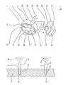
- an air mover device 1 comprising two sensors 2 according to a first embodiment is shown in a perspective view.
- the sensors 2 are fixed to a surface 4 shown in sections, which are, for instance, damp areas in rooms, such as walls, wall portions, ceiling or floors.
- the at least one air mover device 1 preferably serves for the drying of damp walls or wall portions of a room or other surfaces during construction, for instance in order to eliminate damage of a building by water.
- the air mover device 1 comprises an air mover 6 having a rotor unit 7 which is pivoted through a fixing bracket 8.
- the fixing bracket 8 in turn is rotatably mounted to a base 10.
- the rotor unit 7 has a hollow cylindrical rotor housing 12 encompassing a rotor 14 or rather fan, wherein a housing axis and a rotor axis extend substantially coaxially with respect to each other.
- the rotor 14 includes plural blades 16 fixed to a rotor head 18.
- the rotor 14 is driven, for instance, by an electric drive motor not shown in the figure.
- An airflow extending approximately axially with respect to the rotor axis of the rotor 14 is generated by rotation of the rotor 14.
- the air is conveyed from the rotor 14 via an inlet 20 of the rotor housing 12 to an outlet 22.
- the hollow cylindrical rotor housing 12 has a bearing on the flow direction of the airflow downstream of the outlet 22.
- the rotor housing 12 is pivoted about a first swivel axis 24 between the approximately U-shaped fixing bracket 8.
- the swivel axis 24 extends approximately perpendicularly to the housing axis or rotor axis.
- At least one or two electric geared motors 26 disposed at end portions of the fixing bracket 8 support and swivel the rotor housing 12.
- the fixing bracket 8 is supported at the base 10 via a further geared motor 28 and by the geared motor 28 is rotatable about a second swivel axis 30.
- the latter is arranged approximately perpendicularly to the floor area and to the first swivel axis 24.
- the rotor unit 7 is rotatable about the swivel axis 24 and about the swivel axis 30 of the fixing bracket 8 in all directions of the room so that the airflow can be aligned in any direction.
- the airflow generated by the rotor 14 serves for drying the damp surfaces 4.
- the airflow is directed to a surface 4 to be dried. In this way, a convective flow is generated at the surface and thus the surface 4 is dehumidified.
- the sensors 2 include a rod-shaped sensor portion 34 inserted in a recess 32 of the surface 4 respectively. Said sensor portion 34 is used for measuring the relative humidity and/or temperature in the surface 4 in the area of the recess 32.
- the sensor 2 moreover has a sensor unit 36 projecting away from the surface 4 and including a transmitter through which the reading - i.e. the humidity and/or temperature of the wall portion - is transmitted as measuring signal 38.
- the measuring signal 38 is received and processed by an Electronic Control Unit (ECU) 40 disposed in the base 10 of the air mover 6.
- the ECU 40 can also be a separate device positioned in an additional housing.
- the latter detect the swivel angle and the swivel direction of the rotor unit 7 with respect to the two swivel axes 24, 30. They are arranged, for instance, in the area of the geared motors 26, 28. The swivel angle and the swivel direction are transmitted to the ECU 40 in the form of an electric signal.
- the directions of the rotor unit 7 and/or the airflow to the respective sensors 2 are stored in the ECU 40.
- the rotor unit 7 is alternately aligned toward each sensor 2 prior to the start of a drying process and the respective position of the rotor unit 7 - detected by the rotary encoders 42 - is stored along with a sensor identification of a respective sensor 2 in a memory connected to the ECU 40.
- the data are stored by the fact that, after a respective alignment of the rotor unit 7 toward one of the sensors 2, a user confirms them through a control panel 44 connected to the ECU 40 and the corresponding swivel angles of the rotor unit 7 and the sensor identification of the sensors 2 are then stored in the memory.
- each sensor 2 transmits its GPS position to the ECU 40 which then can swivel the rotor unit 7 in the direction of each sensor 2.
- GPS Global Positioning System
- the ECU 40 receives the measuring signal from each sensor 2 and processes the same. Accordingly, the sensor 2 measuring the highest humidity is determined, for instance. Then the ECU 40 controls the rotor unit 7 via the geared motors 26, 28 so that the airflow passes in the direction of the sensor 2 having the highest measuring value for humidity.
- the ECU 40 delivers a signal to the outside, for instance to a hand-held phone, with several information, for instance the actual condition of the drying process ("moisture in %" or "end of operation, room dry”).
- the delivering of the signal can be made by a GSM (Global System for Mobile Communication) module which is connected with the ECU 40.
- GSM Global System for Mobile Communication
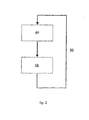
- FIG. 2 shows a flow diagram of a method of controlling the air mover device 1.
- the ECU 40 calculates the highest reading of humidity and in a second process step 48 the airflow generated by the air mover 6 is directed by the ECU 40 approximately in the direction of the sensor 2 reporting the highest reading of humidity. The higher the humidity in the wall portion, the more humidity is removed by convection.
- These steps 46, 48 are repeated shown by the arrow 50 in figure 2 .
- the ECU 40 directs the airflow to the other sensor 2.
- the airflow always points to the direction in which the highest humidity of the surface 4 is measured and thus the largest quantity of humidity can be removed, whereby rapid and thus energy-saving drying of the surface 4 is permitted.
- the air mover 6 alternately directs the airflow approximately in the direction of each sensor 2.
- the period of flow during which the airflow passes in the direction of a sensor 2 depends on the humidity measured by said sensor 2 in proportion to the readings of humidity of the other sensors 2. For instance, the higher the humidity measured by a sensor 2, the longer is also the flow period during which the respective wall portion is aired by the airflow.
- the flow period is calculated by the ECU 40.
- air mover devices for example two, can be employed. They can be arranged in a room in such way that turbulence occurs.
- the air mover 6 in figure 1 can also have an integrated heater controlling the airflow temperature (embodiments of the air mover device with a heater are described in the figures 3 to 5 ).
- the sensors 2 can relay information about the airflow temperature to the ECU 40 which can decide whether the addition of thermal energy from the integrated heater is required. If the airflow is heated by the integrated heater the fan speed of the air mover 6 can change the air-off temperature of the airflow. The higher the fan speed the lower the temperature of the heated airflow. Alternatively it could be controlled the heater on/off time, for example by a constant airflow or fan speed.
- the air mover device 52 according to a second embodiment is shown in a perspective view.
- the air mover 53 has an elongate housing 54 having the form of a canon and is pivot-mounted on a u-shaped fixing bracket 56 essentially at his balance point.
- the fixing bracket 56 has according to the first embodiment at least one electric geared motor 57 disposed at end portions of the fixing bracket 56 support and swivel the housing 54 essentially around its cross axis.
- the fixing bracket 56 is supported at a base 58 via a further geared motor 60 and by the geared motor 60 is rotatable about a second swivel axis.
- the base 58 has three legs 62, 64, 66 arranged such that the base 60 provides a safe stand.
- the essentially cylindrically housing 54 has at each face side a nozzle 68, 70.
- the nozzle 68 (right side of the housing 54 in figure 3 ) is an air inlet nozzle 68 and the nozzle 70 is an air outlet nozzle 70 accelerating the air flow streaming out.
- Within the housing 54 is a fan.
- the air mover device 52 inlets air through the nozzle 68 and blows air out through the nozzle 70.
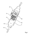
- Figure 4 shows the air mover 71 of an air mover device according to a third embodiment.
- the housing 72 of the air mover 71 equates essentially the housing 54 according to figure 3 but also has an ECU 76 and an electric heater 74 illustrated in a cutaway view of the housing 72.
- the electric heater 74 compared to a gas heater has the advantage that there is no unshielded flame (which can be dangerous). Also the air heated by a gas heater is more humidified compared to an electric heater.
- the heater 74 is arranged upstream of the rotor 78 and has plural heat-elements 80. These are supported at the housing 54 and arranged essentially transverse to the flow direction of the air. A temperature of the air flow 82 streaming out of the nozzle 70 is adjustable by the heat output of the heater 74 independent of an air flow rate.
- the heater 70 is controlled by the ECU 76. For example if the airflow is zero or nearly zero the heater 74 is stopped by the ECU 76 preventing damage.
- the positioning of the hot airflow 82 is carried out according to the air mover device in figure 1 by the geared motor 57, 60 of the fixing bracket 56 in figure 3 .
- FIG 5 a fourth embodiment of the air mover device 84 is shown.
- the air mover device 84 has a stationary unit 86 according to the unit shown in figure 4 and a pivotable air mover 87 having the shape of a diffusor 88 connecting with the stationary unit 86 by a flexible hose 90.
- the unit 86 has a fan and a heater (see figure 4 ) controlled by an ECU 91.
- a base frame 92 bears the unit 86 essentially in a horizontal position.
- On an air outlet nozzle 94 a first end section 96 of the hose 90 is attached.
- the other end section 98 is attached to an inlet 100 of the pivotable diffusor 88.
- a housing of the nozzle 88 has three parts: the essentially cylindrical inlet 100, a truncated cone shaped middle section 102 and an also essentially cylindrical outlet 104 having a greater diameter than the inlet 100.
- a mounting 106 of the air mover 87 corresponds to the mounting of the air mover 53 in figure 3 .
- air mover device 84 In action of the air mover device 84 air streams through a inlet nozzle 108 into the unit 86 due to the fan within the unit 86. Inside the unit 86 the air is heated by the heater and streams to the outlet nozzle 94 into the hose 90. From this the hot air gets into the diffusor 88 and streams out afterwards.
- the unit 86 is also useable in a combination with a room dryer as described in the document GB 2462066 A . Thereby the unit 86 is arranged upstream of a dryer unit so that air is heated by the unit 86 before it is dried by the dryer unit.
- the air mover devices in the figures 1 to 5 can be plugged at an electric ring main. If there are more than one air mover device plugged it is important not to overload the ring main. To avoid this it is possible that the air mover devices communicate with each other with usual means.
- the ECUs of the air mover devices determine which one of the air mover devices should be energised at a given time. For example it is always the air mover device activated having to dry the wettest walls.
- the invention discloses an air mover device for drying damp walls or wall portions by at least one air mover.
- Said air mover generates airflow which is controllable by an adjusting unit.
- the adjusting unit is designed so that the airflow can be automatically controlled toward any direction in the room.
Landscapes
- Engineering & Computer Science (AREA)
- Mechanical Engineering (AREA)
- General Engineering & Computer Science (AREA)
- Drying Of Solid Materials (AREA)
Description
- The invention relates to an air mover device and a method of controlling such air mover device.
- Publication
US 2004/0022631 A1 discloses an air mover according to the preamble of claim 1. - In publication
U.S. 2005/0257394 A1 an air mover device for drying damp rooms is disclosed. Said device comprises a housing having an air inlet and an air outlet. A rotor which generates airflow between the air inlet and the air outlet is arranged in the housing. Upstream of the air outlet a turbine driven by a motor is disposed, the airflow generated by the rotor absorbing waste heat from the motor. Thus, hot air flows through the air outlet into the room to be dried. Moreover, air is pumped through a passage via the turbine. The passage is connected to a base plate spaced apart from a floor of the room, whereby air provided between the floor and the base plate is sucked toward the passage. A convective flow occurs between the floor and the base plate to remove the humidity prevailing in the floor. - This solution has the drawback that such air mover device has an extremely complex structure and requires a large amount of energy to drive the rotor and the turbine.
- Compared to that, it is the object underlying the invention to provide an air mover device and a method of controlling such air mover device for inexpensive and energy-saving drying of damp areas in rooms, such as walls, ceiling or floors.
- This object is achieved by an air mover device in accordance with the features of claim 1 and by a method of controlling such air mover device according to the features of the
claims 15 and 16. - In accordance with the invention, an air mover device includes - for drying a surface, especially a damp wall or wall portion - at least one air mover for generating airflow. The airflow is controllable by an adjusting unit which has such configuration that the airflow is automatically controllable essentially into any direction of the room.
- This solution has the advantage that high dynamics of the ambient air are developed by varying the airflow into any directions of the room, whereby dehumidifying of the walls or wall portions is accelerated by reason of high convection. Energy is saved by the more rapid drying process of the walls or wall portions.
- The adjusting unit is controlled by an Electronic Control Unit (ECU), thus allowing control, for instance, of different motion patterns of the airflow.
- At least one sensor is provided which serves especially for detecting humidity and/or a temperature of a wall, a wall portion or other surfaces. The airflow is controlled in response to a measuring signal of the at least one sensor transmitted to the ECU.
- In this way, during a motion pattern, the airflow can be directed primarily to a damp area of the wall measured by the sensor and the wall can be dehumidified substantially in this area by convection. If the temperature and/or humidity value of the wall then falls below a predetermined value, the air mover can be switched off, for instance, in order to save energy.
- Preferably a plurality of sensors is provided for measuring the humidity of one or more walls or wall portions, whereby it is possible, for example, to always direct the airflow to the dampest wall portion or the dampest wall.
- The measuring signal can be transmitted extremely flexibly through wireless connection from the sensor to the ECU. This is carried out, for instance, electromagnetically, optically or acoustically. Also, a wire connection could be used between the sensor and the ECU and in this way, compared to the wireless connection, a transmitter and a receiver could be saved.
- A position of the at least one sensor can preferably be transmitted to the ECU via a GPS signal received by the sensor or is manually entered into the ECU via a control panel.
- In a further embodiment of the invention, the air mover includes a rotor driven by an electric motor which is movable by the adjusting unit for varying the flow direction of the airflow.
- In order to pivot the rotor into all directions of the room, preferably a first swivel axis extending approximately transversely to a drive axis of the rotor and a second swivel axis extending approximately transversely to the first swivel axis are provided.
- It is preferred that the rotor is pivoted by conventional and inexpensive geared motors assigned to the swivel axes.
- The swivel axes may be operatively connected to a respective rotary encoder to determine the current flow direction of the airflow. Said rotary encoders then report the respective swivel angle to the ECU.
- At least one further air mover may be provided to generate a further airflow, the latter then being aligned with respect to the first airflow so as to form turbulence in the room.
- In order to permit an extremely flexible drying of a wall or a wall portion the flow direction and/or the flow rate and/or the temperature of the airflow is controllable. The flow rate is then varied, for instance, by the rotational speed of the rotor and the temperature can be adjusted, for example, by a heater operatively connected to the airflow.
- In a first preferred method of controlling an air mover device the airflow is directed approximately in the direction of the sensor reporting the highest reading of humidity. In this way, drying of a wall or a wall portion is possible within a short drying period, as the convection due to the airflow is most efficient in the area of the highest humidity, which entails saving of energy.
- In a further preferred method the airflow is alternately directed approximately toward each sensor, the period of flow during which the airflow is directed approximately to one of the sensors depending on the measured humidity of said sensor or all sensors. The advantage is that walls or wall portions exhibiting high humidity can be aired during a longer flow period than walls or wall portions exhibiting less humidity which, in turn, results in a short drying period and, consequently, in saving of energy.
- In a further especially simple method the airflow is varied in a pattern predetermined by the ECU.
- Other advantageous further developments of the invention are the subject matter of further subclaims.
- Hereinafter a preferred embodiment of the invention is illustrated by way of schematic drawing. The drawings show:
-
Fig. 1 a perspective view of an air mover device including pertinent sensors; -
Fig. 2 a flow diagram of a method of controlling such a air mover device; -
Fig. 3 a perspective view of an air mover device according to a second embodiment; -
Fig. 4 a perspective view of an air mover device according to a third embodiment and -
Fig. 5 a perspective view of an air mover device according to a fourth embodiment. - In the
figure 1 an air mover device 1 comprising twosensors 2 according to a first embodiment is shown in a perspective view. Thesensors 2 are fixed to asurface 4 shown in sections, which are, for instance, damp areas in rooms, such as walls, wall portions, ceiling or floors. The at least one air mover device 1 preferably serves for the drying of damp walls or wall portions of a room or other surfaces during construction, for instance in order to eliminate damage of a building by water. - The air mover device 1 comprises an
air mover 6 having a rotor unit 7 which is pivoted through afixing bracket 8. Thefixing bracket 8 in turn is rotatably mounted to abase 10. - The rotor unit 7 has a hollow
cylindrical rotor housing 12 encompassing arotor 14 or rather fan, wherein a housing axis and a rotor axis extend substantially coaxially with respect to each other. Therotor 14 includesplural blades 16 fixed to arotor head 18. Therotor 14 is driven, for instance, by an electric drive motor not shown in the figure. - An airflow extending approximately axially with respect to the rotor axis of the
rotor 14 is generated by rotation of therotor 14. The air is conveyed from therotor 14 via aninlet 20 of therotor housing 12 to anoutlet 22. The hollowcylindrical rotor housing 12 has a bearing on the flow direction of the airflow downstream of theoutlet 22. - The
rotor housing 12 is pivoted about a firstswivel axis 24 between the approximatelyU-shaped fixing bracket 8. Theswivel axis 24 extends approximately perpendicularly to the housing axis or rotor axis. At least one or two electric gearedmotors 26 disposed at end portions of thefixing bracket 8 support and swivel therotor housing 12. - The
fixing bracket 8 is supported at thebase 10 via a further gearedmotor 28 and by the gearedmotor 28 is rotatable about a secondswivel axis 30. The latter is arranged approximately perpendicularly to the floor area and to the firstswivel axis 24. Through the gearedmotors swivel axis 24 and about theswivel axis 30 of thefixing bracket 8 in all directions of the room so that the airflow can be aligned in any direction. - The airflow generated by the
rotor 14 serves for drying the damp surfaces 4. For this purpose, the airflow is directed to asurface 4 to be dried. In this way, a convective flow is generated at the surface and thus thesurface 4 is dehumidified. - In order to accelerate the drying process of the
damp surface 4,several sensors 2 are provided, two of saidsensors 2 being exemplified in the figure. Thesensors 2 include a rod-shapedsensor portion 34 inserted in arecess 32 of thesurface 4 respectively. Saidsensor portion 34 is used for measuring the relative humidity and/or temperature in thesurface 4 in the area of therecess 32. Thus the arrangement of thesensor portion 34 in therecess 32 is needed for creating a microenvironment to measure the temperature and relative humidity in particular in a brick of the wall. Thesensor 2 moreover has asensor unit 36 projecting away from thesurface 4 and including a transmitter through which the reading - i.e. the humidity and/or temperature of the wall portion - is transmitted as measuringsignal 38. The measuringsignal 38 is received and processed by an Electronic Control Unit (ECU) 40 disposed in thebase 10 of theair mover 6. TheECU 40 can also be a separate device positioned in an additional housing. - For determining the position of the rotor unit 7 and, thus, for determining the flow direction of the
airflow rotary encoders 42 are provided. The latter detect the swivel angle and the swivel direction of the rotor unit 7 with respect to the twoswivel axes motors ECU 40 in the form of an electric signal. - The directions of the rotor unit 7 and/or the airflow to the
respective sensors 2 are stored in theECU 40. For this purpose, the rotor unit 7 is alternately aligned toward eachsensor 2 prior to the start of a drying process and the respective position of the rotor unit 7 - detected by the rotary encoders 42 - is stored along with a sensor identification of arespective sensor 2 in a memory connected to theECU 40. The data are stored by the fact that, after a respective alignment of the rotor unit 7 toward one of thesensors 2, a user confirms them through acontrol panel 44 connected to theECU 40 and the corresponding swivel angles of the rotor unit 7 and the sensor identification of thesensors 2 are then stored in the memory. - It is also possible that the position of the
sensors 2 is determined by a Global Positioning System (GPS). To this effect, eachsensor 2 transmits its GPS position to theECU 40 which then can swivel the rotor unit 7 in the direction of eachsensor 2. - At predetermined time intervals or non-stop the
ECU 40 receives the measuring signal from eachsensor 2 and processes the same. Accordingly, thesensor 2 measuring the highest humidity is determined, for instance. Then theECU 40 controls the rotor unit 7 via the gearedmotors sensor 2 having the highest measuring value for humidity. - It is supposable that the
ECU 40 delivers a signal to the outside, for instance to a hand-held phone, with several information, for instance the actual condition of the drying process ("moisture in %" or "end of operation, room dry"). The delivering of the signal can be made by a GSM (Global System for Mobile Communication) module which is connected with theECU 40. - Different methods of controlling the air mover device 1 are possible for rapid and thus energy-saving drying of the
damp walls 4, which will be explained hereinafter. -
Figure 2 shows a flow diagram of a method of controlling the air mover device 1. In this method in afirst process step 46 theECU 40 calculates the highest reading of humidity and in asecond process step 48 the airflow generated by theair mover 6 is directed by theECU 40 approximately in the direction of thesensor 2 reporting the highest reading of humidity. The higher the humidity in the wall portion, the more humidity is removed by convection. Thesesteps arrow 50 infigure 2 . Thus, if the reading of humidity of thesensor 2 falls below the reading of humidity of anothersensor 2 which is spaced apart therefrom, theECU 40 directs the airflow to theother sensor 2. Thus, the airflow always points to the direction in which the highest humidity of thesurface 4 is measured and thus the largest quantity of humidity can be removed, whereby rapid and thus energy-saving drying of thesurface 4 is permitted. - In another method the
air mover 6 alternately directs the airflow approximately in the direction of eachsensor 2. In this case, the period of flow during which the airflow passes in the direction of asensor 2 depends on the humidity measured by saidsensor 2 in proportion to the readings of humidity of theother sensors 2. For instance, the higher the humidity measured by asensor 2, the longer is also the flow period during which the respective wall portion is aired by the airflow. The flow period is calculated by theECU 40. - It is also possible to program the air mover device 1 via the
control panel 44 independently of thesensors 2. In this way, the user can determine a particular motion pattern of the airflow. - Furthermore, also several air mover devices 1, for example two, can be employed. They can be arranged in a room in such way that turbulence occurs.
- The
air mover 6 infigure 1 can also have an integrated heater controlling the airflow temperature (embodiments of the air mover device with a heater are described in thefigures 3 to 5 ). Thus thesensors 2 can relay information about the airflow temperature to theECU 40 which can decide whether the addition of thermal energy from the integrated heater is required. If the airflow is heated by the integrated heater the fan speed of theair mover 6 can change the air-off temperature of the airflow. The higher the fan speed the lower the temperature of the heated airflow. Alternatively it could be controlled the heater on/off time, for example by a constant airflow or fan speed. - In the
figure 3 theair mover device 52 according to a second embodiment is shown in a perspective view. Theair mover 53 has anelongate housing 54 having the form of a canon and is pivot-mounted on au-shaped fixing bracket 56 essentially at his balance point. The fixingbracket 56 has according to the first embodiment at least one electric gearedmotor 57 disposed at end portions of the fixingbracket 56 support and swivel thehousing 54 essentially around its cross axis. - The fixing
bracket 56 is supported at abase 58 via a further gearedmotor 60 and by the gearedmotor 60 is rotatable about a second swivel axis. Thebase 58 has threelegs base 60 provides a safe stand. - The essentially cylindrically
housing 54 has at each face side anozzle housing 54 infigure 3 ) is anair inlet nozzle 68 and thenozzle 70 is anair outlet nozzle 70 accelerating the air flow streaming out. Within thehousing 54 is a fan. Theair mover device 52 inlets air through thenozzle 68 and blows air out through thenozzle 70. -
Figure 4 shows theair mover 71 of an air mover device according to a third embodiment. Thehousing 72 of theair mover 71 equates essentially thehousing 54 according tofigure 3 but also has anECU 76 and anelectric heater 74 illustrated in a cutaway view of thehousing 72. Theelectric heater 74 compared to a gas heater has the advantage that there is no unshielded flame (which can be dangerous). Also the air heated by a gas heater is more humidified compared to an electric heater. - The
heater 74 is arranged upstream of therotor 78 and has plural heat-elements 80. These are supported at thehousing 54 and arranged essentially transverse to the flow direction of the air. A temperature of theair flow 82 streaming out of thenozzle 70 is adjustable by the heat output of theheater 74 independent of an air flow rate. Theheater 70 is controlled by theECU 76. For example if the airflow is zero or nearly zero theheater 74 is stopped by theECU 76 preventing damage. The positioning of thehot airflow 82 is carried out according to the air mover device infigure 1 by the gearedmotor bracket 56 infigure 3 . - In
figure 5 a fourth embodiment of theair mover device 84 is shown. In difference to the previous embodiments theair mover device 84 has astationary unit 86 according to the unit shown infigure 4 and apivotable air mover 87 having the shape of adiffusor 88 connecting with thestationary unit 86 by aflexible hose 90. - The
unit 86 has a fan and a heater (seefigure 4 ) controlled by anECU 91. Abase frame 92 bears theunit 86 essentially in a horizontal position. On an air outlet nozzle 94 afirst end section 96 of thehose 90 is attached. Theother end section 98 is attached to aninlet 100 of thepivotable diffusor 88. A housing of thenozzle 88 has three parts: the essentiallycylindrical inlet 100, a truncated cone shapedmiddle section 102 and an also essentiallycylindrical outlet 104 having a greater diameter than theinlet 100. - A mounting 106 of the
air mover 87 corresponds to the mounting of theair mover 53 infigure 3 . - In action of the
air mover device 84 air streams through ainlet nozzle 108 into theunit 86 due to the fan within theunit 86. Inside theunit 86 the air is heated by the heater and streams to theoutlet nozzle 94 into thehose 90. From this the hot air gets into thediffusor 88 and streams out afterwards. - The
unit 86 is also useable in a combination with a room dryer as described in the documentGB 2462066 A unit 86 is arranged upstream of a dryer unit so that air is heated by theunit 86 before it is dried by the dryer unit. - The air mover devices in the
figures 1 to 5 can be plugged at an electric ring main. If there are more than one air mover device plugged it is important not to overload the ring main. To avoid this it is possible that the air mover devices communicate with each other with usual means. The ECUs of the air mover devices determine which one of the air mover devices should be energised at a given time. For example it is always the air mover device activated having to dry the wettest walls. - The invention discloses an air mover device for drying damp walls or wall portions by at least one air mover. Said air mover generates airflow which is controllable by an adjusting unit. The adjusting unit is designed so that the airflow can be automatically controlled toward any direction in the room.
-
- 1
- air mover device
- 2
- sensor
- 4
- surface
- 6
- air mover
- 7
- rotor unit
- 8
- fixing bracket
- 10
- base
- 12
- rotor housing
- 14
- rotor
- 16
- blade
- 18
- rotor head
- 20
- inlet
- 22
- outlet
- 24
- swivel axis
- 26
- geared motor
- 28
- geared motor
- 30
- swivel axis
- 32
- recess
- 34
- sensor portion
- 36
- sensor unit
- 38
- measuring signal
- 40
- ECU
- 42
- rotary encoder
- 44
- control panel
- 46
- process step
- 48
- process step
- 50
- arrow
- 52
- air mover device
- 53
- air mover
- 54
- housing
- 56
- fixing bracket
- 57
- geared motor
- 58
- base
- 60
- geared motor
- 62
- leg
- 64
- leg
- 66
- leg
- 68
- nozzle
- 70
- nozzle
- 71
- air mover
- 72
- housing
- 74
- heater
- 76
- ECU
- 78
- fan
- 80
- heat-element
- 82
- air flow
- 84
- air mover device
- 86
- unit
- 87
- air mover
- 88
- diffusor
- 90
- hose
- 91
- ECU
- 92
- base frame
- 94
- outlet nozzle
- 96
- end section
- 98
- end section
- 100
- inlet
- 102
- middle section
- 104
- outlet
- 106
- mounting
- 108
- inlet nozzle
Claims (16)
- An air mover device for drying at least one surface (4) comprising at least one air mover (6; 53; 71; 87) by which an airflow controllable by an adjusting unit (26, 28; 57, 60) is generateable, wherein the airflow is controllable automatically by the adjusting unit (26, 28; 57, 60) essentially to any direction in space, characterized in that the adjusting unit (26, 28; 57, 60) is controlled by an Electronic Control Unit (ECU) (40; 76), wherein at least one sensor (2) for detecting humidity and/or temperature of the at least one surface (4) is provided and wherein the air mover device is adapted to control the airflow in response to a measuring signal (38) of the at least one sensor (2) transmitted to the ECU (40; 76).
- An air mover device according to claim 1, wherein a plurality of sensors (2) is provided at the at least one surface (4).
- An air mover device according to claim 1 or 2, wherein the measuring signal (38) is transmitted from the at least one sensor (2) to the ECU (40; 76) electrically, electronically, optically or acoustically with or without wire connection.
- An air mover device according to any one of the claims 1 to 3, wherein a position of the at least one sensor (2) is detectable automatically by the ECU (40; 76), especially via a GPS signal, or stored by a control panel (44) connected to the ECU (40; 76).
- An air mover device according to any one of the preceding claims, wherein the air mover (6; 53; 71; 87) includes a rotor (14; 78) adapted to be pivoted by the adjusting unit (26, 28; 57, 60) for varying the direction of the airflow in the room.
- An air mover device according to claim 5, wherein the rotor (14; 78) is adapted to be pivoted about a first swivel axis (24) extending approximately transversely to a drive axis and about a second swivel axis (30) extending approximately transversely to the first swivel axis (24).
- An air mover device according to claim 6, wherein the rotor (14) is pivoted about the swivel axes (24, 30) via geared motors (26, 28; 57, 60).
- An air mover device according to claim 6 or 7, wherein a respective rotary encoder (42) is operatively connected to a swivel axis (24, 30) to measure a pivoting angle, the respective pivoting angle being reported to the ECU (40).
- An air mover device according to any one of the preceding claims, comprising two air movers (6; 53; 71; 87), wherein the two airflows thereof are aligned such that turbulence is formed especially in a room defined by the surfaces (4).
- An air mover device according to any one of the preceding claims, wherein the direction of flow and/or the flow rate and/or the temperature of the airflow are controllable.
- An air mover device according to any one of the proceeding claims, whereby a heater (74) is provided for adjusting the temperature of the airflow.
- An air mover device according to claim 11, whereby the air mover (53; 71) has the heater (74).
- An air mover device according to any one of the preceding claims, whereby the air mover (87), especially formed as a diffusor (88), is connected to a unit (86), especially by a hose (90), whereby the unit (86) has the rotor and/ or the heater.
- An air mover device according to any one of the preceding claims, whereby this is applicable as a fan heater, for drying surfaces and/ or in combination with a room dryer.
- A method of controlling an air mover device according to anyone of the claims 2 to 14, wherein the airflow is directed approximately toward the sensor (2) reporting the highest reading of humidity and/or of temperature.
- A method of controlling an air mover device according to any one of the claims 2 to 14, wherein the airflow is alternately directed approximately toward each sensor (2), the period of flow during which the airflow points approximately to the direction of one of the sensors (2) being dependent on the humidity and/or temperature measured by said sensor (2) or by all sensors (2).
Priority Applications (1)
| Application Number | Priority Date | Filing Date | Title |
|---|---|---|---|
| EP10739864.6A EP2457050B1 (en) | 2009-07-24 | 2010-07-26 | Air mover device |
Applications Claiming Priority (3)
| Application Number | Priority Date | Filing Date | Title |
|---|---|---|---|
| EP09009641A EP2278242A1 (en) | 2009-07-24 | 2009-07-24 | Air mover device |
| PCT/EP2010/004566 WO2011009640A1 (en) | 2009-07-24 | 2010-07-26 | Air mover device |
| EP10739864.6A EP2457050B1 (en) | 2009-07-24 | 2010-07-26 | Air mover device |
Publications (2)
| Publication Number | Publication Date |
|---|---|
| EP2457050A1 EP2457050A1 (en) | 2012-05-30 |
| EP2457050B1 true EP2457050B1 (en) | 2015-09-02 |
Family
ID=41450029
Family Applications (2)
| Application Number | Title | Priority Date | Filing Date |
|---|---|---|---|
| EP09009641A Ceased EP2278242A1 (en) | 2009-07-24 | 2009-07-24 | Air mover device |
| EP10739864.6A Not-in-force EP2457050B1 (en) | 2009-07-24 | 2010-07-26 | Air mover device |
Family Applications Before (1)
| Application Number | Title | Priority Date | Filing Date |
|---|---|---|---|
| EP09009641A Ceased EP2278242A1 (en) | 2009-07-24 | 2009-07-24 | Air mover device |
Country Status (4)
| Country | Link |
|---|---|
| EP (2) | EP2278242A1 (en) |
| AU (1) | AU2010275702A1 (en) |
| DK (1) | DK2457050T3 (en) |
| WO (1) | WO2011009640A1 (en) |
Families Citing this family (5)
| Publication number | Priority date | Publication date | Assignee | Title |
|---|---|---|---|---|
| CA2873102A1 (en) * | 2012-05-10 | 2013-11-14 | Norgren Automation Solutions, Llc | Method and apparatus for automatically drying wet floors |
| DE102019126146A1 (en) * | 2019-09-27 | 2021-04-01 | Hochschule für Technik und Wirtschaft Dresden | Ventilation device for walls and / or corners in interior areas |
| DE102020134204A1 (en) | 2020-12-18 | 2022-06-23 | Ebm-Papst St. Georgen Gmbh & Co. Kg | Forced ventilation unit for ventilation of a closed air space |
| CN114068191B (en) * | 2021-11-29 | 2022-05-27 | 四川省雅安新江浩科技有限公司 | Method for manufacturing anode foil for high-voltage electrolytic capacitor |
| PL444181A1 (en) * | 2023-03-23 | 2023-11-20 | Tabiś Krzysztof Aquapol Polska Cpv | Measuring probe and system for measuring construction parameters, especially walls of buildings |
Citations (1)
| Publication number | Priority date | Publication date | Assignee | Title |
|---|---|---|---|---|
| US20040022631A1 (en) * | 2002-08-05 | 2004-02-05 | Birdsell Walter G. | Tower fan |
Family Cites Families (16)
| Publication number | Priority date | Publication date | Assignee | Title |
|---|---|---|---|---|
| US2810060A (en) * | 1955-09-12 | 1957-10-15 | Samuel E Tullis | Mobile heating and drying unit |
| DE1902483U (en) * | 1964-05-11 | 1964-10-15 | Horst Reich | RHYTHMIC DRYER. |
| DE3321673C2 (en) * | 1983-06-15 | 1985-05-30 | Max 8908 Krumbach Wagner | Method and device for drying ceramic moldings |
| US5097672A (en) * | 1988-11-18 | 1992-03-24 | Daikin Industries Ltd. | Spot air-conditioner |
| DE3920955C1 (en) * | 1989-06-27 | 1990-11-29 | Hans Lingl Anlagenbau Und Verfahrenstechnik Gmbh & Co Kg, 7910 Neu-Ulm, De | |
| GB2242017B (en) * | 1990-02-16 | 1994-04-20 | Management & Guidance Services | Dehumidifying apparatus |
| US5180333A (en) * | 1991-10-28 | 1993-01-19 | Norm Pacific Automation Corp. | Ventilation device adjusted and controlled automatically with movement of human body |
| DE19937193B4 (en) * | 1999-08-06 | 2006-01-19 | Tiemo Sehon | Process for drying hydrous basecoat, and equipment and retrofit kit for paint booths for carrying out the process |
| JP2001347933A (en) * | 2000-06-06 | 2001-12-18 | Kamigaki Takeo | Repairing device for vehicle |
| SE523473C2 (en) | 2001-08-17 | 2004-04-20 | Corroventa Avfuktning Ab | Method and apparatus for drying a water damaged building |
| DE10143540A1 (en) | 2001-09-06 | 2003-04-03 | Wolfgang Ludwig | Eliminating/inhibiting moisture deposits on internal building walls subject to condensation involves forced ventilation if temperature at wall surface below computed dew point temperature |
| CA2527275A1 (en) * | 2005-11-17 | 2007-05-17 | Dryair Inc. | Controlling humidity in zones during a drying process |
| DE102004019952A1 (en) * | 2004-04-23 | 2005-11-17 | Fraunhofer-Gesellschaft zur Förderung der angewandten Forschung e.V. | Moisture detection device for detecting condensation in rooms and on interior wall surfaces |
| US7173538B2 (en) * | 2004-06-25 | 2007-02-06 | Rm2, Inc. | Apparatus, system and method for monitoring a drying procedure |
| US7243050B2 (en) * | 2005-03-05 | 2007-07-10 | Armstrong Jay T | Devices and systems for remote and automated monitoring and control of water removal, mold remediation, and similar work |
| GB2462066B (en) | 2008-07-18 | 2010-06-16 | Dbk Technitherm Ltd | Improvements in and relating to drying of water damaged buildings |
-
2009
- 2009-07-24 EP EP09009641A patent/EP2278242A1/en not_active Ceased
-
2010
- 2010-07-26 WO PCT/EP2010/004566 patent/WO2011009640A1/en not_active Ceased
- 2010-07-26 AU AU2010275702A patent/AU2010275702A1/en not_active Abandoned
- 2010-07-26 EP EP10739864.6A patent/EP2457050B1/en not_active Not-in-force
- 2010-07-26 DK DK10739864.6T patent/DK2457050T3/en active
Patent Citations (1)
| Publication number | Priority date | Publication date | Assignee | Title |
|---|---|---|---|---|
| US20040022631A1 (en) * | 2002-08-05 | 2004-02-05 | Birdsell Walter G. | Tower fan |
Also Published As
| Publication number | Publication date |
|---|---|
| EP2457050A1 (en) | 2012-05-30 |
| WO2011009640A1 (en) | 2011-01-27 |
| AU2010275702A1 (en) | 2012-02-16 |
| DK2457050T3 (en) | 2015-12-14 |
| EP2278242A1 (en) | 2011-01-26 |
Similar Documents
| Publication | Publication Date | Title |
|---|---|---|
| DK2457050T3 (en) | Air Interior | |
| EP3177876B1 (en) | Method and device for dehumidification | |
| RU2569784C2 (en) | Adjustment of radial clearances between working blade tops and channel walls | |
| WO2010122117A1 (en) | Ventilation system involving ultrasonic flow measurement | |
| JP2008061733A (en) | Clothing drying system | |
| PL343405A1 (en) | Condensation clothes drier | |
| JP6421585B2 (en) | Grain dryer | |
| CA2512874C (en) | Method and apparatus for fluid flow control | |
| JP2016017717A (en) | Fluid transport device | |
| JP2016145673A (en) | Ventilation system | |
| JP2006280434A (en) | Clothing dryer system | |
| EP3022353B1 (en) | Air flow pressure compensator system for clothes dryers | |
| KR200482171Y1 (en) | Blowing apparatus for laundry dryer | |
| US20240302251A1 (en) | Monitoring device and method for monitoring the quality of a gas atmosphere | |
| NL1036988C2 (en) | CENTRAL VENTILATION SYSTEM. | |
| JPWO2024013971A5 (en) | ||
| JP5266905B2 (en) | Wind direction changing device and dryer using the same | |
| JP3680236B2 (en) | Ventilation control device for home ventilation system | |
| US20180045422A1 (en) | Desiccant drying system | |
| JP2890996B2 (en) | Hot air heater | |
| JP5610797B2 (en) | Dehumidifier | |
| DK2282136T3 (en) | Controlled, dual-flow mechanical ventilation system for a building | |
| JP4115863B2 (en) | Indoor ventilation system | |
| FI105500B (en) | Device for drying building structures | |
| EP3216914A1 (en) | Laundry dryer with humidity sensors |
Legal Events
| Date | Code | Title | Description |
|---|---|---|---|
| PUAI | Public reference made under article 153(3) epc to a published international application that has entered the european phase |
Free format text: ORIGINAL CODE: 0009012 |
|
| 17P | Request for examination filed |
Effective date: 20120223 |
|
| AK | Designated contracting states |
Kind code of ref document: A1 Designated state(s): AL AT BE BG CH CY CZ DE DK EE ES FI FR GB GR HR HU IE IS IT LI LT LU LV MC MK MT NL NO PL PT RO SE SI SK SM TR |
|
| DAX | Request for extension of the european patent (deleted) | ||
| RAP1 | Party data changed (applicant data changed or rights of an application transferred) |
Owner name: DBK DAVID + BAADER GMBH |
|
| 17Q | First examination report despatched |
Effective date: 20140227 |
|
| GRAP | Despatch of communication of intention to grant a patent |
Free format text: ORIGINAL CODE: EPIDOSNIGR1 |
|
| INTG | Intention to grant announced |
Effective date: 20150310 |
|
| RIN1 | Information on inventor provided before grant (corrected) |
Inventor name: JAYNE, JONATHAN Inventor name: HOPKIN, IAN, DAVID |
|
| GRAS | Grant fee paid |
Free format text: ORIGINAL CODE: EPIDOSNIGR3 |
|
| GRAA | (expected) grant |
Free format text: ORIGINAL CODE: 0009210 |
|
| AK | Designated contracting states |
Kind code of ref document: B1 Designated state(s): AL AT BE BG CH CY CZ DE DK EE ES FI FR GB GR HR HU IE IS IT LI LT LU LV MC MK MT NL NO PL PT RO SE SI SK SM TR |
|
| REG | Reference to a national code |
Ref country code: GB Ref legal event code: FG4D |
|
| REG | Reference to a national code |
Ref country code: AT Ref legal event code: REF Ref document number: 746869 Country of ref document: AT Kind code of ref document: T Effective date: 20150915 Ref country code: CH Ref legal event code: EP Ref country code: CH Ref legal event code: NV Representative=s name: ISLER AND PEDRAZZINI AG, CH |
|
| REG | Reference to a national code |
Ref country code: SE Ref legal event code: TRGR |
|
| REG | Reference to a national code |
Ref country code: IE Ref legal event code: FG4D |
|
| REG | Reference to a national code |
Ref country code: DE Ref legal event code: R096 Ref document number: 602010027181 Country of ref document: DE |
|
| REG | Reference to a national code |
Ref country code: DK Ref legal event code: T3 Effective date: 20151208 |
|
| REG | Reference to a national code |
Ref country code: AT Ref legal event code: MK05 Ref document number: 746869 Country of ref document: AT Kind code of ref document: T Effective date: 20150902 |
|
| PG25 | Lapsed in a contracting state [announced via postgrant information from national office to epo] |
Ref country code: FI Free format text: LAPSE BECAUSE OF FAILURE TO SUBMIT A TRANSLATION OF THE DESCRIPTION OR TO PAY THE FEE WITHIN THE PRESCRIBED TIME-LIMIT Effective date: 20150902 Ref country code: LV Free format text: LAPSE BECAUSE OF FAILURE TO SUBMIT A TRANSLATION OF THE DESCRIPTION OR TO PAY THE FEE WITHIN THE PRESCRIBED TIME-LIMIT Effective date: 20150902 Ref country code: NO Free format text: LAPSE BECAUSE OF FAILURE TO SUBMIT A TRANSLATION OF THE DESCRIPTION OR TO PAY THE FEE WITHIN THE PRESCRIBED TIME-LIMIT Effective date: 20151202 Ref country code: GR Free format text: LAPSE BECAUSE OF FAILURE TO SUBMIT A TRANSLATION OF THE DESCRIPTION OR TO PAY THE FEE WITHIN THE PRESCRIBED TIME-LIMIT Effective date: 20151203 Ref country code: LT Free format text: LAPSE BECAUSE OF FAILURE TO SUBMIT A TRANSLATION OF THE DESCRIPTION OR TO PAY THE FEE WITHIN THE PRESCRIBED TIME-LIMIT Effective date: 20150902 |
|
| REG | Reference to a national code |
Ref country code: LT Ref legal event code: MG4D Ref country code: NL Ref legal event code: MP Effective date: 20150902 |
|
| PG25 | Lapsed in a contracting state [announced via postgrant information from national office to epo] |
Ref country code: AT Free format text: LAPSE BECAUSE OF FAILURE TO SUBMIT A TRANSLATION OF THE DESCRIPTION OR TO PAY THE FEE WITHIN THE PRESCRIBED TIME-LIMIT Effective date: 20150902 Ref country code: ES Free format text: LAPSE BECAUSE OF FAILURE TO SUBMIT A TRANSLATION OF THE DESCRIPTION OR TO PAY THE FEE WITHIN THE PRESCRIBED TIME-LIMIT Effective date: 20150902 Ref country code: PL Free format text: LAPSE BECAUSE OF FAILURE TO SUBMIT A TRANSLATION OF THE DESCRIPTION OR TO PAY THE FEE WITHIN THE PRESCRIBED TIME-LIMIT Effective date: 20150902 |
|
| PG25 | Lapsed in a contracting state [announced via postgrant information from national office to epo] |
Ref country code: IS Free format text: LAPSE BECAUSE OF FAILURE TO SUBMIT A TRANSLATION OF THE DESCRIPTION OR TO PAY THE FEE WITHIN THE PRESCRIBED TIME-LIMIT Effective date: 20160102 Ref country code: IT Free format text: LAPSE BECAUSE OF FAILURE TO SUBMIT A TRANSLATION OF THE DESCRIPTION OR TO PAY THE FEE WITHIN THE PRESCRIBED TIME-LIMIT Effective date: 20150902 Ref country code: SK Free format text: LAPSE BECAUSE OF FAILURE TO SUBMIT A TRANSLATION OF THE DESCRIPTION OR TO PAY THE FEE WITHIN THE PRESCRIBED TIME-LIMIT Effective date: 20150902 Ref country code: EE Free format text: LAPSE BECAUSE OF FAILURE TO SUBMIT A TRANSLATION OF THE DESCRIPTION OR TO PAY THE FEE WITHIN THE PRESCRIBED TIME-LIMIT Effective date: 20150902 Ref country code: NL Free format text: LAPSE BECAUSE OF FAILURE TO SUBMIT A TRANSLATION OF THE DESCRIPTION OR TO PAY THE FEE WITHIN THE PRESCRIBED TIME-LIMIT Effective date: 20150902 Ref country code: CZ Free format text: LAPSE BECAUSE OF FAILURE TO SUBMIT A TRANSLATION OF THE DESCRIPTION OR TO PAY THE FEE WITHIN THE PRESCRIBED TIME-LIMIT Effective date: 20150902 |
|
| PG25 | Lapsed in a contracting state [announced via postgrant information from national office to epo] |
Ref country code: RO Free format text: LAPSE BECAUSE OF FAILURE TO SUBMIT A TRANSLATION OF THE DESCRIPTION OR TO PAY THE FEE WITHIN THE PRESCRIBED TIME-LIMIT Effective date: 20150902 Ref country code: PT Free format text: LAPSE BECAUSE OF FAILURE TO SUBMIT A TRANSLATION OF THE DESCRIPTION OR TO PAY THE FEE WITHIN THE PRESCRIBED TIME-LIMIT Effective date: 20160104 |
|
| REG | Reference to a national code |
Ref country code: DE Ref legal event code: R097 Ref document number: 602010027181 Country of ref document: DE |
|
| PLBE | No opposition filed within time limit |
Free format text: ORIGINAL CODE: 0009261 |
|
| STAA | Information on the status of an ep patent application or granted ep patent |
Free format text: STATUS: NO OPPOSITION FILED WITHIN TIME LIMIT |
|
| REG | Reference to a national code |
Ref country code: FR Ref legal event code: PLFP Year of fee payment: 7 |
|
| 26N | No opposition filed |
Effective date: 20160603 |
|
| PG25 | Lapsed in a contracting state [announced via postgrant information from national office to epo] |
Ref country code: SI Free format text: LAPSE BECAUSE OF FAILURE TO SUBMIT A TRANSLATION OF THE DESCRIPTION OR TO PAY THE FEE WITHIN THE PRESCRIBED TIME-LIMIT Effective date: 20150902 |
|
| PGFP | Annual fee paid to national office [announced via postgrant information from national office to epo] |
Ref country code: CH Payment date: 20160726 Year of fee payment: 7 |
|
| PGFP | Annual fee paid to national office [announced via postgrant information from national office to epo] |
Ref country code: FR Payment date: 20160722 Year of fee payment: 7 |
|
| PG25 | Lapsed in a contracting state [announced via postgrant information from national office to epo] |
Ref country code: BE Free format text: LAPSE BECAUSE OF FAILURE TO SUBMIT A TRANSLATION OF THE DESCRIPTION OR TO PAY THE FEE WITHIN THE PRESCRIBED TIME-LIMIT Effective date: 20150902 |
|
| PG25 | Lapsed in a contracting state [announced via postgrant information from national office to epo] |
Ref country code: MC Free format text: LAPSE BECAUSE OF FAILURE TO SUBMIT A TRANSLATION OF THE DESCRIPTION OR TO PAY THE FEE WITHIN THE PRESCRIBED TIME-LIMIT Effective date: 20150902 |
|
| REG | Reference to a national code |
Ref country code: IE Ref legal event code: MM4A |
|
| PG25 | Lapsed in a contracting state [announced via postgrant information from national office to epo] |
Ref country code: IE Free format text: LAPSE BECAUSE OF NON-PAYMENT OF DUE FEES Effective date: 20160726 |
|
| PG25 | Lapsed in a contracting state [announced via postgrant information from national office to epo] |
Ref country code: LU Free format text: LAPSE BECAUSE OF NON-PAYMENT OF DUE FEES Effective date: 20160726 |
|
| REG | Reference to a national code |
Ref country code: CH Ref legal event code: PL |
|
| REG | Reference to a national code |
Ref country code: FR Ref legal event code: ST Effective date: 20180330 |
|
| PG25 | Lapsed in a contracting state [announced via postgrant information from national office to epo] |
Ref country code: CH Free format text: LAPSE BECAUSE OF NON-PAYMENT OF DUE FEES Effective date: 20170731 Ref country code: LI Free format text: LAPSE BECAUSE OF NON-PAYMENT OF DUE FEES Effective date: 20170731 |
|
| PG25 | Lapsed in a contracting state [announced via postgrant information from national office to epo] |
Ref country code: SM Free format text: LAPSE BECAUSE OF FAILURE TO SUBMIT A TRANSLATION OF THE DESCRIPTION OR TO PAY THE FEE WITHIN THE PRESCRIBED TIME-LIMIT Effective date: 20150902 Ref country code: FR Free format text: LAPSE BECAUSE OF NON-PAYMENT OF DUE FEES Effective date: 20170731 Ref country code: HU Free format text: LAPSE BECAUSE OF FAILURE TO SUBMIT A TRANSLATION OF THE DESCRIPTION OR TO PAY THE FEE WITHIN THE PRESCRIBED TIME-LIMIT; INVALID AB INITIO Effective date: 20100726 Ref country code: CY Free format text: LAPSE BECAUSE OF FAILURE TO SUBMIT A TRANSLATION OF THE DESCRIPTION OR TO PAY THE FEE WITHIN THE PRESCRIBED TIME-LIMIT Effective date: 20150902 |
|
| PG25 | Lapsed in a contracting state [announced via postgrant information from national office to epo] |
Ref country code: MK Free format text: LAPSE BECAUSE OF FAILURE TO SUBMIT A TRANSLATION OF THE DESCRIPTION OR TO PAY THE FEE WITHIN THE PRESCRIBED TIME-LIMIT Effective date: 20150902 Ref country code: TR Free format text: LAPSE BECAUSE OF FAILURE TO SUBMIT A TRANSLATION OF THE DESCRIPTION OR TO PAY THE FEE WITHIN THE PRESCRIBED TIME-LIMIT Effective date: 20150902 Ref country code: HR Free format text: LAPSE BECAUSE OF FAILURE TO SUBMIT A TRANSLATION OF THE DESCRIPTION OR TO PAY THE FEE WITHIN THE PRESCRIBED TIME-LIMIT Effective date: 20150902 Ref country code: MT Free format text: LAPSE BECAUSE OF NON-PAYMENT OF DUE FEES Effective date: 20160731 |
|
| PG25 | Lapsed in a contracting state [announced via postgrant information from national office to epo] |
Ref country code: BG Free format text: LAPSE BECAUSE OF FAILURE TO SUBMIT A TRANSLATION OF THE DESCRIPTION OR TO PAY THE FEE WITHIN THE PRESCRIBED TIME-LIMIT Effective date: 20150902 |
|
| PG25 | Lapsed in a contracting state [announced via postgrant information from national office to epo] |
Ref country code: AL Free format text: LAPSE BECAUSE OF FAILURE TO SUBMIT A TRANSLATION OF THE DESCRIPTION OR TO PAY THE FEE WITHIN THE PRESCRIBED TIME-LIMIT Effective date: 20150902 |
|
| PGFP | Annual fee paid to national office [announced via postgrant information from national office to epo] |
Ref country code: DE Payment date: 20190628 Year of fee payment: 10 Ref country code: DK Payment date: 20190723 Year of fee payment: 10 Ref country code: SE Payment date: 20190725 Year of fee payment: 10 |
|
| REG | Reference to a national code |
Ref country code: DE Ref legal event code: R119 Ref document number: 602010027181 Country of ref document: DE |
|
| REG | Reference to a national code |
Ref country code: DK Ref legal event code: EBP Effective date: 20200731 |
|
| REG | Reference to a national code |
Ref country code: SE Ref legal event code: EUG |
|
| PG25 | Lapsed in a contracting state [announced via postgrant information from national office to epo] |
Ref country code: DE Free format text: LAPSE BECAUSE OF NON-PAYMENT OF DUE FEES Effective date: 20210202 Ref country code: SE Free format text: LAPSE BECAUSE OF NON-PAYMENT OF DUE FEES Effective date: 20200727 |
|
| PG25 | Lapsed in a contracting state [announced via postgrant information from national office to epo] |
Ref country code: DK Free format text: LAPSE BECAUSE OF NON-PAYMENT OF DUE FEES Effective date: 20200731 |
|
| PGFP | Annual fee paid to national office [announced via postgrant information from national office to epo] |
Ref country code: GB Payment date: 20210722 Year of fee payment: 12 |
|
| GBPC | Gb: european patent ceased through non-payment of renewal fee |
Effective date: 20220726 |
|
| PG25 | Lapsed in a contracting state [announced via postgrant information from national office to epo] |
Ref country code: GB Free format text: LAPSE BECAUSE OF NON-PAYMENT OF DUE FEES Effective date: 20220726 |