EP2456232A1 - Howling canceller - Google Patents
Howling canceller Download PDFInfo
- Publication number
- EP2456232A1 EP2456232A1 EP10799870A EP10799870A EP2456232A1 EP 2456232 A1 EP2456232 A1 EP 2456232A1 EP 10799870 A EP10799870 A EP 10799870A EP 10799870 A EP10799870 A EP 10799870A EP 2456232 A1 EP2456232 A1 EP 2456232A1
- Authority
- EP
- European Patent Office
- Prior art keywords
- howling
- microphones
- frequency component
- frequency
- microphone
- Prior art date
- Legal status (The legal status is an assumption and is not a legal conclusion. Google has not performed a legal analysis and makes no representation as to the accuracy of the status listed.)
- Granted
Links
Images


Classifications
-
- H—ELECTRICITY
- H04—ELECTRIC COMMUNICATION TECHNIQUE
- H04M—TELEPHONIC COMMUNICATION
- H04M9/00—Arrangements for interconnection not involving centralised switching
- H04M9/08—Two-way loud-speaking telephone systems with means for conditioning the signal, e.g. for suppressing echoes for one or both directions of traffic
- H04M9/082—Two-way loud-speaking telephone systems with means for conditioning the signal, e.g. for suppressing echoes for one or both directions of traffic using echo cancellers
-
- H—ELECTRICITY
- H04—ELECTRIC COMMUNICATION TECHNIQUE
- H04R—LOUDSPEAKERS, MICROPHONES, GRAMOPHONE PICK-UPS OR LIKE ACOUSTIC ELECTROMECHANICAL TRANSDUCERS; ELECTRIC HEARING AIDS; PUBLIC ADDRESS SYSTEMS
- H04R3/00—Circuits for transducers
- H04R3/02—Circuits for transducers for preventing acoustic reaction, i.e. acoustic oscillatory feedback
Definitions
- the invention relates to a howling canceller that suppresses howling occurring in an acoustic feedback loop.
- a howling canceller of Patent Document 1 has a plurality of notch filters and is connected between a microphone and an amplifier provided at a subsequent stage of the microphone. When a frequency component at which the howling occurs is detected, the howling canceller allots the notch filter to the detected frequency, thereby suppressing the howling.
- Patent Document 1 discloses a case where the howling is suppressed in a loop in which one microphone and one speaker are provided. Accordingly, when the notch filter is simply allotted to the frequency at which the howling is detected, the howling can be suppressed.
- the acoustic feedback loop is configured for each of the microphones. Hence, it is not possible to simply determine that the howling is occurring in which acoustic feedback loop (sound signal picked up by the microphone).
- the howling canceller of Patent Document 1 is connected to a subsequent stage of each microphone. Then, when the howling occurs in any one of acoustic feedback loops, all the howling cancellers connected to the subsequent stages of the respective microphones allot the notch filters to the same frequencies as the frequency component at which the howling is occurring.
- the frequency component at which the howling is detected is suppressed even in the acoustic feedback loop in which the howling does not occur. That is, in the acoustic feedback loop in which the howling does not occur, even a frequency component that should not be originally suppressed is suppressed.
- an object of the invention is to provide a howling canceller that can attenuate a frequency component at which howling is occurring only for a sound signal picked up by a microphone in which the howling is occurring, under environments in which a synthesized sound signal, which is obtained by synthesizing sound signals picked up by a plurality of microphones, is emitted from a speaker.
- a howling canceller that is adapted to an acoustic system having a speaker and a plurality of microphones. A plurality of acoustic feedback loops are formed by the speaker and each of the microphones.
- the howling canceller comprises a howling suppressing unit that performs suppression processing of detecting frequency components at which howling is possibly occurring in each of sound signals picked up by the respective microphones, comparing the detected frequency components of the sound signals picked up by the microphones each other on frequency basis and detecting a frequency component having maximum power, and suppressing the frequency component having the maximum power in the sound signal including the frequency component having the maximum power.
- the howling suppressing unit includes: a howling possibility detection unit that detects the frequency components at which howling is possibly occurring in each of the sound signals picked up by the microphones; and a howling determination unit that compares the frequency components of the sound signals, which are detected by the howling possibility detection unit, each other on the frequency basis and determines the frequency component having maximum power on the frequency basis. Based on a determination result of the howling determination unit, the howling suppressing unit inserts a notch filter for suppressing the frequency component into the sound signal including the determined frequency component.
- the howling possibility detection unit detects the frequency component having the power of the predetermined value or larger, as the frequency component at which the howling is possibly occurring.
- a plurality of the howling suppressing units are respectively provided between a synthesis unit that synthesizes the sound signals output from the microphones and the microphones.
- the howling suppressing unit repeatedly performs the suppression processing.
- the howling canceller of the invention can suppress only the frequency component of the sound signal at which the howling occurs in the acoustic feedback system having the plurality of acoustic feedback loops. Thereby, the howling canceller can prevent the frequency component, which should not be suppressed, from being suppressed.
- FIG. 1 is a block diagram showing functions and configurations of the acoustic system.
- the acoustic system 100A includes a microphone M1, a microphone M2, a howling canceller 10, an adder 3, an amplifier 4 and a speaker S.
- acoustic system 100A sound signals (hereinafter, also referred to as sound pickup signals) picked up by the microphone M1 and the microphone M2 are added in the adder 3, and the added sound signal is amplified in the amplifier 4 and the amplified signal is output to the speaker S.
- sound pickup signals hereinafter, also referred to as sound pickup signals picked up by the microphone M1 and the microphone M2 are added in the adder 3, and the added sound signal is amplified in the amplifier 4 and the amplified signal is output to the speaker S.
- acoustic feedback loops in which the microphone M1 and the microphone M2 again pick up the sound emitted from the speaker S are formed due to a relation of an arrangement position between the speaker S and the microphones M1, M2 or an environment in which the speaker and the microphones are arranged.
- the howling canceller 10 performs howling suppression processing, thereby suppressing the howling.
- the acoustic feedback loop L1 has the microphone M1, the howling canceller 10, the adder 3, the amplifier 4 and the speaker S.
- the acoustic feedback loop L2 has the microphone M2, the howling canceller 10, the adder 3, the amplifier 4 and the speaker S.
- the microphone M1 and the microphone M2 output the sound signals to the howling canceller 10, respectively.
- the howling canceller 10 has a howling detection unit 1A, a howling detection unit 1B and a howling determination unit 2 and suppresses the howling that is occurring in the acoustic feedback loop L1 and the acoustic feedback loop L2.
- the sound pickup signal from the microphone M1 is input to the howling detection unit 1A of the howling canceller 10 and the sound pickup signal from the microphone M2 is input to the howling detection unit 1B of the howling canceller 10.
- the howling detection unit 1A and the howling detection unit 1B have the same function and configuration, they are described as a howling detection unit 1.
- the howling detection unit 1 has an FFT processing unit 11, a howling possibility detection unit 12 and a notch filter 13.
- the sound pickup signal is input to the FFT processing unit 11 and the notch filter 13.
- the FFT processing unit 11 is a fast Fourier transform processing circuit, converts the sound pickup signal, which is a function of a time domain, into a sound pickup signal that is a function of a frequency domain, and outputs the same to the howling possibility detection unit 12.
- the howling possibility detection unit 12 detects that the howling is possibly occurring at the corresponding frequency.
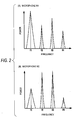
- the howling possibility detection unit 12 outputs information of the frequency components at which the howling shown in FIGS. 2(A) and 2(B) is possibly occurring to the howling determination unit 2.
- FIGS. 2(A) and 2(B) show examples of the frequency components at which the howling is possibly occurring, in which a horizontal axis indicates a frequency and a vertical axis indicates a power value.
- FIG. 2(A) shows the sound signal picked up by the microphone M1
- FIG. 2(B) shows the sound signal picked up by the microphone M2.
- the howling determination unit 2 compares the frequency components each other, which are input from the respective howling possibility detection units 12 of the howling detection unit 1A and the howling detection unit 1B, and determines a frequency component having larger power (for example, frequency components f1, f4 of the microphone M1 in FIG. 2(A) and frequency components f2, f3 of the microphone M2 in FIG. 2(B) ) on a per-frequency basis.
- the howling determination unit 2 determines that the larger power frequency component corresponds to the frequency component becoming the howling, and sets coefficients in the respective notch filters 13 of the howling detection unit 1A and the howling detection unit 1B so as to suppress the larger power frequency components, individually.
- the notch filter 13 is an adaptive IIR filter, for example, and rapidly decreases a gain of a narrow band frequency component to suppress the frequency component.
- the notch filter 13 outputs a sound signal, in which the larger power frequency component (frequency component at which the howling is occurring) is suppressed from the sound pickup signal, to the adder 3.
- the notch filter 13 of the howling detection unit 1A attenuates the frequency components f1, f4 without attenuating the frequency components f2, f3 and outputs the sound signal to the adder 3.
- the notch filter 13 of the howling detection unit 1B attenuates the frequency components f2, f3 without attenuating the frequency components f1, f4 and outputs the sound signal to the adder 3.
- the adder 3 adds the input sound signals and outputs the added signal to the amplifier 4. That is, the adder 3 adds the sound signal, in which the frequency components becoming the howling are suppressed from the sound signal picked up by the microphone M1, and the sound signal, in which the frequency components becoming the howling are suppressed from the sound signal picked up by the microphone M2.
- the amplifier 4 amplifies the sound signal input from the adder 3 and outputs the amplified sound signal to the speaker S.
- the speaker S emits the sound, based on the input sound signal.
- the howling canceller 10 can specify the frequency components at which the howling is occurring in each of the sound signals picked up by the microphones, it is possible to suppress only the frequency components at which the howling is occurring in each of the sound signals picked up by the microphones. That is, regarding the frequency at which the howling is occurring in the sound signal picked up by the other microphone, the howling canceller 10 does not erroneously suppress the frequency component of the sound signal picked up by a microphone at which the howling does not occur. As a result, the howling canceller 10 does not suppress the frequency components of the sound signals beyond necessity, so that the sound signal to be output is less deteriorated.
- FIG. 3 is a flowchart showing the howling suppression processing.
- the microphone M1 picks up surrounding sound to generate a sound signal and outputs the sound signal to the FFT processing unit 11 and the notch filter 13 of the howling detection unit 1A of the howling canceller 10. Also, the microphone M2 picks up a surrounding sound to generate a sound signal and outputs the sound signal to the FFT processing unit 11 and the notch filter 13 of the howling detection unit 1B (S101).
- the respective FFT processing units 11 of the howling detection unit 1A and the howling detection unit 1B convert the input sound signals into frequency spectra and output the converted frequency spectra to the howling possibility detection units 12, respectively (S102).
- the respective howling possibility detection units 12 of the howling detection unit 1A and the howling detection unit 1B detect that the howling is possibly occurring at the frequency components having power of a predetermined value or larger of the frequency spectra and output the detected frequency components to the howling determination unit 2, respectively (S103).
- the howling determination unit 2 compares the respective frequency components input from the respective howling possibility detection units 12 of the howling detection unit 1A and the howling detection unit 1B and determines the lager power frequency component on a per-frequency basis (S104).
- the howling determination unit 2 individually sets coefficients in the respective notch filters 13 of the howling detection unit 1A and the howling detection unit 1B so as to suppress the larger power frequency components (S105).
- the respective notch filters 13 of the howling detection unit 1A and the howling detection unit 1B output the sound signals, in which the larger power frequency components are suppressed from the sound pickup signals input from the microphone M1 and the microphone M2, to the adder 3.
- the sound signal added in the adder 3 is amplified in the amplifier 4 and then output to the speaker S (S106). Then, returning to the process of S101, the processes are sequentially repeated.
- the howling canceller 10 can suppress even the frequency component that has not been suppressed in one howling suppression processing. Accordingly, the howling canceller 10 can suppress the howling that is occurring in the acoustic system 100A, correctly and securely.
- the howling of the frequency component f1 of FIGS. 2(A) and 2(B) is caused due to not only the acoustic feedback loop L1 but also the acoustic feedback loop L2
- the frequency component f1 of the acoustic feedback loop L2 remains.
- by repeatedly performing the howling suppression processing it is possible to detect even the howling of the frequency component f1 of the acoustic feedback loop L2, which could not been suppressed, so that it is possible to suppress the howling.
- the number of the microphones is not limited to two and may be three or more.
- the howling canceller 10 since the acoustic feedback loops corresponding to the number of the microphones are formed in the acoustic system 100A, the howling canceller 10 has only to include the howling detection units 1 corresponding to the number of the acoustic feedback loops.
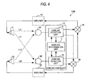
- FIG. 4 is a block diagram showing functions and configurations of the acoustic system according to the second illustrative embodiment.
- the acoustic system 100B includes the microphone M1, the microphone M2, the howling canceller 10, an adder 3A, an adder 3B, an amplifier 4A, an amplifier 4B, a speaker S1 and a speaker S2.
- the acoustic system 100B shown in FIG. 4 adds sound signals picked up by the microphone M1 and the microphone M2 in the adder 3A and the adder 3B, respectively, amplifies the sound signal, which is output from the adder 3A, in the amplifier 4A and amplifies the sound signal, which is output from the adder 3B, in the amplifier 4B. Then, the acoustic system 100B outputs the sound signal amplified in the amplifier 4A to the speaker S1 and outputs the sound signal amplified in the amplifier 4B to the speaker S2. At this time, in the acoustic system 100B, acoustic feedback loops in which the microphone M1 and the microphone M2 again pick up the sounds emitted from the speaker S1 and the speaker S2 are formed.
- the howling canceller 10 performs howling suppression processing, thereby suppressing the howling.
- acoustic feedback loops L11, L12, L21, L22 are realistically formed.
- the acoustic feedback loop L11 has the microphone M1, the howling canceller 10, the adder 3A, the amplifier 4A and the speaker S1.
- the acoustic feedback loop L12 has the microphone M1, the howling canceller 10, the adder 3B, the amplifier 4B and the speaker S2.
- the acoustic feedback loop L21 has the microphone M2, the howling canceller 10, the adder 3A, the amplifier 4A and the speaker S1.
- the acoustic feedback loop L22 has the microphone M2, the howling canceller 10, the adder 3B, the amplifier 4B and the speaker S2.
- the sound signals picked up by the microphone M1 and the microphone M2 are respectively output to the howling detection unit 1A and the howling detection unit 1B of the howling canceller 10.
- the sound signal picked up by the microphone M1 includes the sound signal (sound signal having transmitted through the acoustic feedback loop L11) output from the speaker S1 and the sound signal (sound signal having transmitted through the acoustic feedback loop L12) output from the speaker S2.
- the sound signal picked up by the microphone M2 includes the sound signal (sound signal having transmitted through the acoustic feedback loop L21) output from the speaker S1 and the sound signal (sound signal having transmitted through the acoustic feedback loop L22) output from the speaker S2.
- the howling detection unit 1A detects, from the sound signal picked up by the microphone M1, frequency components at which the howling is possibly occurring, and the howling detection unit 1B detects, from the sound signal picked up by the microphone M2, frequency components at which the howling is possibly occurring.
- the howling determination unit 2 compares the frequency components detected by the howling detection unit 1A and the howling detection unit 1B, respectively, and determines a frequency component having larger power on a per-frequency basis.
- the howling determination unit 2 sets coefficients in the notch filter 13 of the howling detection unit 1A and the notch filter 13 of the howling detection unit 1B so as to suppress the larger power frequency components.
- the howling canceller 10 can specify the frequency components at which the howling is occurring in each of the sound signals picked up by the microphones. Therefore, the howling canceller 10 can suppress only the sound signal picked up by a microphone, which includes the frequency component at which the howling is occurring in the sound signal picked up by the other microphone. That is, the howling canceller 10 does not suppress the frequency component of the same frequency as the frequency component at which the howling is occurring, from the sound signal picked up by the microphone for which it is determined that the frequency component at which the howling is occurring is not included. As a result, the howling canceller 10 does not suppress the frequency components of the sound signals beyond necessity, so that the sound signal to be output is less deteriorated.
- the number of the microphones and the number of the speakers are not limited to two and may be three or more.
- the howling canceller 10 has only to include the howling detection units 1 corresponding to the number of the microphones.
- the howling canceller of the invention is applied to an acoustic system having one or more speakers and a plurality of microphones.
- the acoustic system has a plurality of acoustic feedback loops in which the sound is emitted from the speakers, based on the sound signals picked up by the microphones, and the sound emitted from the speakers is again picked up by the microphones.
- the howling canceller has the howling suppressing unit that performs the howling suppression processing.
- the howling suppressing unit detects the frequency components at which the howling is possibly occurring in each of the sound signals picked up by the microphones. For example, the howling suppressing unit performs the FFT processing in each of the sound signals picked up by the microphones and detects the frequency components having power of a predetermined value or larger, as the frequency component at which the howling is possibly occurring.
- the howling suppressing unit compares the detected frequency components each other in each of the sound signals picked up by the microphones, detects the sound signal having larger power (maximum power) on a per-frequency basis and suppresses the frequency components at which the howling is occurring in each of the sound signals.
- the howling canceller can suppress only the frequency components of the sound signal picked up by the microphone, at which the howling is occurring, and does not suppress the frequency components of the sound signal picked up by the microphone, at which the howling does not occur. Therefore, the howling canceller can suppress the occurring howling without substantially deteriorating the sound signal.
- the howling suppressing unit of the howling canceller of the invention has the howling detection unit and the howling determination unit.
- the howling detection unit detects the frequency components at which the howling is possibly occurring in each of the sound signals picked up by the microphones.
- the howling determination unit detects, from the frequency components at which the howling is possibly occurring, the frequency component having larger power on a per-frequency basis.
- the howling determination unit regards the detected frequency component having larger power on a per-frequency basis as the frequency component that causes the howling, and determines the sound pickup signals of the microphones becoming the howling on a per-frequency basis.
- the howling detection unit inserts the notch filters for each of the acoustic feedback loops so as to suppress the frequency components for which it is determined that the howling is occurring.
- the howling canceller of the invention connects the howling suppressing unit just after the microphones, respectively.
- the howling canceller performs the howling suppression processing before the sound signals of the microphones are synthesized, it is possible to suppress the frequency components becoming the howling in each of the sound signals picked up by the microphones.
- the howling canceller can suppress the frequency components becoming the howling in each of the microphones.
- the howling canceller of the invention repeatedly performs the howling suppression processing.
- the howling canceller can repeat the howling suppression processing, so that it is possible to always suppress the howling.
- the illustrative embodiments simply show the representative examples of the invention and the invention is not limited to the illustrative embodiments. That is, the illustrative embodiments can be variously modified and implemented without departing from the gist of the invention.
- the synthesized sound signal which is obtained by synthesizing the sound signals picked up by the microphones, is emitted from the speaker, it is possible to provide the howling canceller that attenuates the frequency components at which the howling is occurring, only for the sound signal picked up by the microphone at which the howling is occurring.
Landscapes
- Engineering & Computer Science (AREA)
- Signal Processing (AREA)
- Health & Medical Sciences (AREA)
- General Health & Medical Sciences (AREA)
- Otolaryngology (AREA)
- Physics & Mathematics (AREA)
- Acoustics & Sound (AREA)
- Circuit For Audible Band Transducer (AREA)
- Soundproofing, Sound Blocking, And Sound Damping (AREA)
- Reverberation, Karaoke And Other Acoustics (AREA)
Abstract
Description
- The invention relates to a howling canceller that suppresses howling occurring in an acoustic feedback loop.
- Under environments in which an acoustic feedback system is formed in a predetermined space where a speaker and a microphone are provided and a loop in which a sound signal picked up by the microphone is emitted from the speaker and the sound signal is again picked up by the microphone is formed, howling is problematic which occurs as a loop gain of a signal of a specific frequency exceeds 1. In order to suppress the howling, a variety of cancellers have been suggested (for example, refer to Patent Document 1).
- A howling canceller of
Patent Document 1 has a plurality of notch filters and is connected between a microphone and an amplifier provided at a subsequent stage of the microphone. When a frequency component at which the howling occurs is detected, the howling canceller allots the notch filter to the detected frequency, thereby suppressing the howling. - [Patent Document 1]
JP-A-2008-017244 -
Patent Document 1 discloses a case where the howling is suppressed in a loop in which one microphone and one speaker are provided. Accordingly, when the notch filter is simply allotted to the frequency at which the howling is detected, the howling can be suppressed. - However, under circumstances in which a plurality of microphones is arranged and sound signals picked up by the microphones are synthesized and emitted from the speaker, the acoustic feedback loop is configured for each of the microphones. Hence, it is not possible to simply determine that the howling is occurring in which acoustic feedback loop (sound signal picked up by the microphone).
- In this case, generally, the howling canceller of
Patent Document 1 is connected to a subsequent stage of each microphone. Then, when the howling occurs in any one of acoustic feedback loops, all the howling cancellers connected to the subsequent stages of the respective microphones allot the notch filters to the same frequencies as the frequency component at which the howling is occurring. - Therefore, the frequency component at which the howling is detected is suppressed even in the acoustic feedback loop in which the howling does not occur. That is, in the acoustic feedback loop in which the howling does not occur, even a frequency component that should not be originally suppressed is suppressed.
- Accordingly, an object of the invention is to provide a howling canceller that can attenuate a frequency component at which howling is occurring only for a sound signal picked up by a microphone in which the howling is occurring, under environments in which a synthesized sound signal, which is obtained by synthesizing sound signals picked up by a plurality of microphones, is emitted from a speaker.
- In order to achieve the above object, according to the invention, there is provided a howling canceller that is adapted to an acoustic system having a speaker and a plurality of microphones. A plurality of acoustic feedback loops are formed by the speaker and each of the microphones. The howling canceller comprises a howling suppressing unit that performs suppression processing of detecting frequency components at which howling is possibly occurring in each of sound signals picked up by the respective microphones, comparing the detected frequency components of the sound signals picked up by the microphones each other on frequency basis and detecting a frequency component having maximum power, and suppressing the frequency component having the maximum power in the sound signal including the frequency component having the maximum power.
- Preferably, the howling suppressing unit includes: a howling possibility detection unit that detects the frequency components at which howling is possibly occurring in each of the sound signals picked up by the microphones; and a howling determination unit that compares the frequency components of the sound signals, which are detected by the howling possibility detection unit, each other on the frequency basis and determines the frequency component having maximum power on the frequency basis. Based on a determination result of the howling determination unit, the howling suppressing unit inserts a notch filter for suppressing the frequency component into the sound signal including the determined frequency component.
- Preferably, when power of the frequency component in each of the sound signals picked up by the microphones has a predetermined value or larger, the howling possibility detection unit detects the frequency component having the power of the predetermined value or larger, as the frequency component at which the howling is possibly occurring.
- Preferably, a plurality of the howling suppressing units are respectively provided between a synthesis unit that synthesizes the sound signals output from the microphones and the microphones.
- Preferably, the howling suppressing unit repeatedly performs the suppression processing.
- The howling canceller of the invention can suppress only the frequency component of the sound signal at which the howling occurs in the acoustic feedback system having the plurality of acoustic feedback loops. Thereby, the howling canceller can prevent the frequency component, which should not be suppressed, from being suppressed.
-
-
FIG. 1 is a block diagram showing functions and configurations of an acoustic system according to a first illustrative embodiment. -
FIGS. 2(A) and 2(B) show examples of frequency components at which howling is possibly occurring. -
FIG. 3 is a flowchart showing howling suppression processing. -
FIG. 4 is a block diagram showing functions and configurations of an acoustic system according to a second illustrative embodiment. - An
acoustic system 100A having ahowling canceller 10 according to a first illustrative embodiment is described with reference toFIG. 1 andFIGS.2(A) and 2(B) .FIG. 1 is a block diagram showing functions and configurations of the acoustic system. As shown inFIG. 1 , theacoustic system 100A includes a microphone M1, a microphone M2, ahowling canceller 10, an adder 3, an amplifier 4 and a speaker S. - In the
acoustic system 100A, sound signals (hereinafter, also referred to as sound pickup signals) picked up by the microphone M1 and the microphone M2 are added in the adder 3, and the added sound signal is amplified in the amplifier 4 and the amplified signal is output to the speaker S. At this time, in theacoustic system 100A, acoustic feedback loops in which the microphone M1 and the microphone M2 again pick up the sound emitted from the speaker S are formed due to a relation of an arrangement position between the speaker S and the microphones M1, M2 or an environment in which the speaker and the microphones are arranged. Thus, in theacoustic system 100A, since the sound signal (which includes the sound signals picked up by the microphone M1 and the microphone M2) emitted from the speaker S is included in the sound signals picked up by the microphone M1 and the microphone M2, the sound signals picked up by the microphone M1 and the microphone M2 are repeatedly amplified by the amplifier 4, so that a specific frequency component may be strengthened depending on circumstances. As a result, a loop gain of the specific frequency exceeds 1, so that howling occurs. Therefore, in theacoustic system 100A, thehowling canceller 10 performs howling suppression processing, thereby suppressing the howling. - Here, since one speaker and two microphones are present in the
acoustic system 100A, two acoustic feedback loops L1, L2 are present. The acoustic feedback loop L1 has the microphone M1, thehowling canceller 10, the adder 3, the amplifier 4 and the speaker S. The acoustic feedback loop L2 has the microphone M2, thehowling canceller 10, the adder 3, the amplifier 4 and the speaker S. - The microphone M1 and the microphone M2 output the sound signals to the
howling canceller 10, respectively. - The
howling canceller 10 has ahowling detection unit 1A, ahowling detection unit 1B and ahowling determination unit 2 and suppresses the howling that is occurring in the acoustic feedback loop L1 and the acoustic feedback loop L2. The sound pickup signal from the microphone M1 is input to thehowling detection unit 1A of thehowling canceller 10 and the sound pickup signal from the microphone M2 is input to thehowling detection unit 1B of thehowling canceller 10. In the meantime, since thehowling detection unit 1A and thehowling detection unit 1B have the same function and configuration, they are described as ahowling detection unit 1. - The
howling detection unit 1 has anFFT processing unit 11, a howlingpossibility detection unit 12 and anotch filter 13. The sound pickup signal is input to theFFT processing unit 11 and thenotch filter 13. - The
FFT processing unit 11 is a fast Fourier transform processing circuit, converts the sound pickup signal, which is a function of a time domain, into a sound pickup signal that is a function of a frequency domain, and outputs the same to the howlingpossibility detection unit 12. - When power of a frequency component has a predetermined value or larger, for example, the howling
possibility detection unit 12 detects that the howling is possibly occurring at the corresponding frequency. The howlingpossibility detection unit 12 outputs information of the frequency components at which the howling shown inFIGS. 2(A) and 2(B) is possibly occurring to thehowling determination unit 2.FIGS. 2(A) and 2(B) show examples of the frequency components at which the howling is possibly occurring, in which a horizontal axis indicates a frequency and a vertical axis indicates a power value.FIG. 2(A) shows the sound signal picked up by the microphone M1 andFIG. 2(B) shows the sound signal picked up by the microphone M2. - The
howling determination unit 2 compares the frequency components each other, which are input from the respective howlingpossibility detection units 12 of thehowling detection unit 1A and thehowling detection unit 1B, and determines a frequency component having larger power (for example, frequency components f1, f4 of the microphone M1 inFIG. 2(A) and frequency components f2, f3 of the microphone M2 inFIG. 2(B) ) on a per-frequency basis. Thehowling determination unit 2 determines that the larger power frequency component corresponds to the frequency component becoming the howling, and sets coefficients in therespective notch filters 13 of thehowling detection unit 1A and thehowling detection unit 1B so as to suppress the larger power frequency components, individually. - The
notch filter 13 is an adaptive IIR filter, for example, and rapidly decreases a gain of a narrow band frequency component to suppress the frequency component. The notch filter 13 outputs a sound signal, in which the larger power frequency component (frequency component at which the howling is occurring) is suppressed from the sound pickup signal, to the adder 3. For example, in the examples ofFIGS. 2(A) and 2(B) , thenotch filter 13 of thehowling detection unit 1A attenuates the frequency components f1, f4 without attenuating the frequency components f2, f3 and outputs the sound signal to the adder 3. Thenotch filter 13 of thehowling detection unit 1B attenuates the frequency components f2, f3 without attenuating the frequency components f1, f4 and outputs the sound signal to the adder 3. - The adder 3 adds the input sound signals and outputs the added signal to the amplifier 4. That is, the adder 3 adds the sound signal, in which the frequency components becoming the howling are suppressed from the sound signal picked up by the microphone M1, and the sound signal, in which the frequency components becoming the howling are suppressed from the sound signal picked up by the microphone M2.
- The amplifier 4 amplifies the sound signal input from the adder 3 and outputs the amplified sound signal to the speaker S.
- The speaker S emits the sound, based on the input sound signal.
- Since the howling
canceller 10 can specify the frequency components at which the howling is occurring in each of the sound signals picked up by the microphones, it is possible to suppress only the frequency components at which the howling is occurring in each of the sound signals picked up by the microphones. That is, regarding the frequency at which the howling is occurring in the sound signal picked up by the other microphone, the howlingcanceller 10 does not erroneously suppress the frequency component of the sound signal picked up by a microphone at which the howling does not occur. As a result, the howlingcanceller 10 does not suppress the frequency components of the sound signals beyond necessity, so that the sound signal to be output is less deteriorated. - Also, as shown in
FIG. 3 , theacoustic system 100A repeatedly executes the howling suppression processing.FIG. 3 is a flowchart showing the howling suppression processing. - As shown in
FIG. 3 , the microphone M1 picks up surrounding sound to generate a sound signal and outputs the sound signal to theFFT processing unit 11 and thenotch filter 13 of the howlingdetection unit 1A of the howlingcanceller 10. Also, the microphone M2 picks up a surrounding sound to generate a sound signal and outputs the sound signal to theFFT processing unit 11 and thenotch filter 13 of the howlingdetection unit 1B (S101). - The respective
FFT processing units 11 of the howlingdetection unit 1A and the howlingdetection unit 1B convert the input sound signals into frequency spectra and output the converted frequency spectra to the howlingpossibility detection units 12, respectively (S102). - The respective howling
possibility detection units 12 of the howlingdetection unit 1A and the howlingdetection unit 1B detect that the howling is possibly occurring at the frequency components having power of a predetermined value or larger of the frequency spectra and output the detected frequency components to the howlingdetermination unit 2, respectively (S103). - The howling
determination unit 2 compares the respective frequency components input from the respective howlingpossibility detection units 12 of the howlingdetection unit 1A and the howlingdetection unit 1B and determines the lager power frequency component on a per-frequency basis (S104). - The howling
determination unit 2 individually sets coefficients in therespective notch filters 13 of the howlingdetection unit 1A and the howlingdetection unit 1B so as to suppress the larger power frequency components (S105). - The
respective notch filters 13 of the howlingdetection unit 1A and the howlingdetection unit 1B output the sound signals, in which the larger power frequency components are suppressed from the sound pickup signals input from the microphone M1 and the microphone M2, to the adder 3. The sound signal added in the adder 3 is amplified in the amplifier 4 and then output to the speaker S (S106). Then, returning to the process of S101, the processes are sequentially repeated. - Like this, by repeatedly performing the howling suppression processing, the howling
canceller 10 can suppress even the frequency component that has not been suppressed in one howling suppression processing. Accordingly, the howlingcanceller 10 can suppress the howling that is occurring in theacoustic system 100A, correctly and securely. - For example, for a case where the howling of the frequency component f1 of
FIGS. 2(A) and 2(B) is caused due to not only the acoustic feedback loop L1 but also the acoustic feedback loop L2, even when the howling suppression processing is performed for the frequency component f1 of the acoustic feedback loop L1 in the above processing, the frequency component f1 of the acoustic feedback loop L2 remains. However, by repeatedly performing the howling suppression processing, it is possible to detect even the howling of the frequency component f1 of the acoustic feedback loop L2, which could not been suppressed, so that it is possible to suppress the howling. - In the meantime, the number of the microphones is not limited to two and may be three or more. In this case, since the acoustic feedback loops corresponding to the number of the microphones are formed in the
acoustic system 100A, the howlingcanceller 10 has only to include the howlingdetection units 1 corresponding to the number of the acoustic feedback loops. - In a second illustrative embodiment, the howling
canceller 10 is applied to anacoustic system 100B having two speakers and two microphones. The second illustrative embodiment is described with reference toFIG. 4. FIG. 4 is a block diagram showing functions and configurations of the acoustic system according to the second illustrative embodiment. As shown inFIG. 4 , theacoustic system 100B includes the microphone M1, the microphone M2, the howlingcanceller 10, anadder 3A, anadder 3B, anamplifier 4A, anamplifier 4B, a speaker S1 and a speaker S2. - The
acoustic system 100B shown inFIG. 4 adds sound signals picked up by the microphone M1 and the microphone M2 in theadder 3A and theadder 3B, respectively, amplifies the sound signal, which is output from theadder 3A, in theamplifier 4A and amplifies the sound signal, which is output from theadder 3B, in theamplifier 4B. Then, theacoustic system 100B outputs the sound signal amplified in theamplifier 4A to the speaker S1 and outputs the sound signal amplified in theamplifier 4B to the speaker S2. At this time, in theacoustic system 100B, acoustic feedback loops in which the microphone M1 and the microphone M2 again pick up the sounds emitted from the speaker S1 and the speaker S2 are formed. - In this case, in the
acoustic system 100B, since the sound signals (which include the sound signals picked up by the microphone M1 and the microphone M2) emitted from the speaker S1 and the speaker S2 are included in the sound signals picked up by the microphone M1 and the microphone M2, the sound signals picked up by the microphone M1 and the microphone M2 are repeatedly amplified by theamplifier 4A and theamplifier 4B, so that a specific frequency component may be strengthened depending on circumstances. As a result, when a loop gain of the specific frequency exceeds 1, howling occurs. Therefore, in theacoustic system 100B, the howlingcanceller 10 performs howling suppression processing, thereby suppressing the howling. - Here, since two speakers and two microphones are present in the
acoustic system 100B, acoustic feedback loops L11, L12, L21, L22 are realistically formed. The acoustic feedback loop L11 has the microphone M1, the howlingcanceller 10, theadder 3A, theamplifier 4A and the speaker S1. The acoustic feedback loop L12 has the microphone M1, the howlingcanceller 10, theadder 3B, theamplifier 4B and the speaker S2. The acoustic feedback loop L21 has the microphone M2, the howlingcanceller 10, theadder 3A, theamplifier 4A and the speaker S1. The acoustic feedback loop L22 has the microphone M2, the howlingcanceller 10, theadder 3B, theamplifier 4B and the speaker S2. - The sound signals picked up by the microphone M1 and the microphone M2 are respectively output to the howling
detection unit 1A and the howlingdetection unit 1B of the howlingcanceller 10. The sound signal picked up by the microphone M1 includes the sound signal (sound signal having transmitted through the acoustic feedback loop L11) output from the speaker S1 and the sound signal (sound signal having transmitted through the acoustic feedback loop L12) output from the speaker S2. The sound signal picked up by the microphone M2 includes the sound signal (sound signal having transmitted through the acoustic feedback loop L21) output from the speaker S1 and the sound signal (sound signal having transmitted through the acoustic feedback loop L22) output from the speaker S2. - The howling
detection unit 1A detects, from the sound signal picked up by the microphone M1, frequency components at which the howling is possibly occurring, and the howlingdetection unit 1B detects, from the sound signal picked up by the microphone M2, frequency components at which the howling is possibly occurring. The howlingdetermination unit 2 compares the frequency components detected by the howlingdetection unit 1A and the howlingdetection unit 1B, respectively, and determines a frequency component having larger power on a per-frequency basis. The howlingdetermination unit 2 sets coefficients in thenotch filter 13 of the howlingdetection unit 1A and thenotch filter 13 of the howlingdetection unit 1B so as to suppress the larger power frequency components. - Like this, even for the
acoustic system 100B having the plurality of speakers, the howlingcanceller 10 can specify the frequency components at which the howling is occurring in each of the sound signals picked up by the microphones. Therefore, the howlingcanceller 10 can suppress only the sound signal picked up by a microphone, which includes the frequency component at which the howling is occurring in the sound signal picked up by the other microphone. That is, the howlingcanceller 10 does not suppress the frequency component of the same frequency as the frequency component at which the howling is occurring, from the sound signal picked up by the microphone for which it is determined that the frequency component at which the howling is occurring is not included. As a result, the howlingcanceller 10 does not suppress the frequency components of the sound signals beyond necessity, so that the sound signal to be output is less deteriorated. - Also, like the first illustrative embodiment, it is possible to suppress the howling more correctly and securely by repeating the howling suppression processing.
- In the meantime, the number of the microphones and the number of the speakers are not limited to two and may be three or more. In this case, the howling
canceller 10 has only to include the howlingdetection units 1 corresponding to the number of the microphones. - In the below, the operational effects of the invention are described.
The howling canceller of the invention is applied to an acoustic system having one or more speakers and a plurality of microphones. The acoustic system has a plurality of acoustic feedback loops in which the sound is emitted from the speakers, based on the sound signals picked up by the microphones, and the sound emitted from the speakers is again picked up by the microphones. - The howling canceller has the howling suppressing unit that performs the howling suppression processing. The howling suppressing unit detects the frequency components at which the howling is possibly occurring in each of the sound signals picked up by the microphones. For example, the howling suppressing unit performs the FFT processing in each of the sound signals picked up by the microphones and detects the frequency components having power of a predetermined value or larger, as the frequency component at which the howling is possibly occurring. The howling suppressing unit compares the detected frequency components each other in each of the sound signals picked up by the microphones, detects the sound signal having larger power (maximum power) on a per-frequency basis and suppresses the frequency components at which the howling is occurring in each of the sound signals.
- Thereby, in the acoustic system having the plurality of acoustic feedback loops, the howling canceller can suppress only the frequency components of the sound signal picked up by the microphone, at which the howling is occurring, and does not suppress the frequency components of the sound signal picked up by the microphone, at which the howling does not occur. Therefore, the howling canceller can suppress the occurring howling without substantially deteriorating the sound signal.
- Also, the howling suppressing unit of the howling canceller of the invention has the howling detection unit and the howling determination unit. The howling detection unit detects the frequency components at which the howling is possibly occurring in each of the sound signals picked up by the microphones. The howling determination unit detects, from the frequency components at which the howling is possibly occurring, the frequency component having larger power on a per-frequency basis. The howling determination unit regards the detected frequency component having larger power on a per-frequency basis as the frequency component that causes the howling, and determines the sound pickup signals of the microphones becoming the howling on a per-frequency basis. Based on the determination result of the howling determination unit, the howling detection unit inserts the notch filters for each of the acoustic feedback loops so as to suppress the frequency components for which it is determined that the howling is occurring.
- Also, the howling canceller of the invention connects the howling suppressing unit just after the microphones, respectively.
- Thereby, since the howling canceller performs the howling suppression processing before the sound signals of the microphones are synthesized, it is possible to suppress the frequency components becoming the howling in each of the sound signals picked up by the microphones. The howling canceller can suppress the frequency components becoming the howling in each of the microphones.
- Also, the howling canceller of the invention repeatedly performs the howling suppression processing.
- Thereby, even when the howling exists which could not been suppressed in the previous howling suppression processing, the howling canceller can repeat the howling suppression processing, so that it is possible to always suppress the howling.
- The illustrative embodiments simply show the representative examples of the invention and the invention is not limited to the illustrative embodiments. That is, the illustrative embodiments can be variously modified and implemented without departing from the gist of the invention.
- The invention is based on the Japanese Patent Application (Patent Application No.
2009-168558) filed on July 17, 2009 - Under environments in which the synthesized sound signal, which is obtained by synthesizing the sound signals picked up by the microphones, is emitted from the speaker, it is possible to provide the howling canceller that attenuates the frequency components at which the howling is occurring, only for the sound signal picked up by the microphone at which the howling is occurring.
-
- 1, 1A, 1B: howling detection unit
- 10: howling canceller
- 100A, 100B: acoustic system
- 11: FFT processing unit
- 12: howling possibility detection unit
- 13: notch filter
- 2: howling determination unit
- 3, 3A, 3B: adder
- 4, 4A, 4B: amplifier
- L1, L2, L11, L12, L21, L22: acoustic feedback loop
- M1, M2: microphone
- S, S1, S2: speaker
Claims (5)
- A howling canceller that is adapted to an acoustic system having a speaker and a plurality of microphones,
wherein a plurality of acoustic feedback loops are formed by the speaker and each of the microphones; and
wherein the howling canceller comprises a howling suppressing unit that performs suppression processing of detecting frequency components at which howling is possibly occurring in each of sound signals picked up by the respective microphones, comparing the detected frequency components of the sound signals picked up by the microphones each other on frequency basis and detecting a frequency component having maximum power, and suppressing the frequency component having the maximum power in the sound signal including the frequency component having the maximum power. - The howling canceller according to claim 1, wherein the howling suppressing unit includes:a howling possibility detection unit that detects the frequency components at which howling is possibly occurring in each of the sound signals picked up by the microphones; anda howling determination unit that compares the frequency components of the sound signals, which are detected by the howling possibility detection unit, each other on the frequency basis and determines the frequency component having maximum power on the frequency basis; andwherein based on a determination result of the howling determination unit, the howling suppressing unit inserts a notch filter for suppressing the frequency component into the sound signal including the determined frequency component.
- The howling canceller according to claim 2, wherein when power of the frequency component in each of the sound signals picked up by the microphones has a predetermined value or larger, the howling possibility detection unit detects the frequency component having the power of the predetermined value or larger, as the frequency component at which the howling is possibly occurring.
- The howling canceller according to claim 1, wherein a plurality of the howling suppressing units are respectively provided between a synthesis unit that synthesizes the sound signals output from the microphones and the microphones.
- The howling canceller according to claim 1, wherein the howling suppressing unit repeatedly performs the suppression processing.
Applications Claiming Priority (2)
| Application Number | Priority Date | Filing Date | Title |
|---|---|---|---|
| JP2009168558A JP5278219B2 (en) | 2009-07-17 | 2009-07-17 | Howling canceller |
| PCT/JP2010/061922 WO2011007812A1 (en) | 2009-07-17 | 2010-07-14 | Howling canceller |
Publications (3)
| Publication Number | Publication Date |
|---|---|
| EP2456232A1 true EP2456232A1 (en) | 2012-05-23 |
| EP2456232A4 EP2456232A4 (en) | 2014-01-15 |
| EP2456232B1 EP2456232B1 (en) | 2019-04-24 |
Family
ID=43449420
Family Applications (1)
| Application Number | Title | Priority Date | Filing Date |
|---|---|---|---|
| EP10799870.0A Active EP2456232B1 (en) | 2009-07-17 | 2010-07-14 | Howling canceller |
Country Status (5)
| Country | Link |
|---|---|
| US (1) | US8995682B2 (en) |
| EP (1) | EP2456232B1 (en) |
| JP (1) | JP5278219B2 (en) |
| CN (1) | CN102474682B (en) |
| WO (1) | WO2011007812A1 (en) |
Cited By (2)
| Publication number | Priority date | Publication date | Assignee | Title |
|---|---|---|---|---|
| US9749021B2 (en) | 2012-12-18 | 2017-08-29 | Motorola Solutions, Inc. | Method and apparatus for mitigating feedback in a digital radio receiver |
| DE102013000380B4 (en) | 2012-02-23 | 2022-11-17 | Elmos Semiconductor Se | Method for acoustic measurement of the properties of a transmission path of a measurement system between loudspeaker and microphone |
Families Citing this family (15)
| Publication number | Priority date | Publication date | Assignee | Title |
|---|---|---|---|---|
| CN103391496B (en) * | 2013-07-16 | 2016-08-10 | 歌尔声学股份有限公司 | It is applied to active noise and eliminates the chauvent's criterion method and apparatus of ANR earphone |
| KR101607902B1 (en) * | 2014-11-10 | 2016-03-31 | 금오공과대학교 산학협력단 | Apparatus having complex howling removing process |
| US9390154B1 (en) | 2015-08-28 | 2016-07-12 | Swirlds, Inc. | Methods and apparatus for a distributed database within a network |
| US10747753B2 (en) | 2015-08-28 | 2020-08-18 | Swirlds, Inc. | Methods and apparatus for a distributed database within a network |
| RU2746446C2 (en) | 2016-11-10 | 2021-04-14 | Свирлдз, Инк. | Methods and the device for distributed database containing anonymous input data |
| KR102454779B1 (en) | 2016-12-19 | 2022-10-13 | 스월즈, 인크. | Method and apparatus for distributed database enabling deletion of events |
| SG10202103402RA (en) | 2017-07-11 | 2021-05-28 | Swirlds Inc | Methods and apparatus for efficiently implementing a distributed database within a network |
| EP3755005B1 (en) * | 2018-02-16 | 2023-06-07 | Nippon Telegraph And Telephone Corporation | Howling suppression device, method therefor, and program |
| CN108810745B (en) * | 2018-06-13 | 2021-08-31 | 安克创新科技股份有限公司 | Howling test method, howling test system and related devices |
| CN109413728B (en) * | 2018-12-29 | 2022-01-04 | 维沃移动通信有限公司 | Terminal equipment and signal processing method |
| CN109905811B (en) * | 2019-01-24 | 2021-02-26 | 珠海慧联科技有限公司 | Economical acoustic feedback control method and device |
| JP7383942B2 (en) * | 2019-09-06 | 2023-11-21 | ヤマハ株式会社 | In-vehicle sound systems and vehicles |
| EP4226257A4 (en) | 2020-10-06 | 2024-11-06 | Hedera Hashgraph, LLC | METHOD AND DEVICE FOR A DISTRIBUTED DATABASE IN A NETWORK |
| CN113450819B (en) * | 2021-05-21 | 2024-06-18 | 音科思(深圳)技术有限公司 | Signal processing method and related product |
| CN113611276B (en) * | 2021-07-08 | 2024-06-11 | 北京小唱科技有限公司 | Acoustic feedback suppression method, apparatus and storage medium |
Family Cites Families (16)
| Publication number | Priority date | Publication date | Assignee | Title |
|---|---|---|---|---|
| JP3935290B2 (en) * | 1999-06-11 | 2007-06-20 | ティーオーエー株式会社 | Audio broadcasting equipment |
| JP4681163B2 (en) * | 2001-07-16 | 2011-05-11 | パナソニック株式会社 | Howling detection and suppression device, acoustic device including the same, and howling detection and suppression method |
| JP2004023722A (en) * | 2002-06-20 | 2004-01-22 | Matsushita Electric Ind Co Ltd | Howling detection device, suppression device, detection method and suppression method |
| JP3875189B2 (en) | 2002-12-17 | 2007-01-31 | ティーオーエー株式会社 | Howling suppression device |
| JP2004254016A (en) * | 2003-02-19 | 2004-09-09 | Matsushita Electric Ind Co Ltd | Howling suppression device |
| JP3972921B2 (en) | 2004-05-11 | 2007-09-05 | ソニー株式会社 | Voice collecting device and echo cancellation processing method |
| JP2005341129A (en) * | 2004-05-26 | 2005-12-08 | Matsushita Electric Ind Co Ltd | Volume control device |
| US7760888B2 (en) * | 2004-06-16 | 2010-07-20 | Panasonic Corporation | Howling suppression device, program, integrated circuit, and howling suppression method |
| CN1951147B (en) * | 2004-06-16 | 2011-08-17 | 松下电器产业株式会社 | Howling detection device and method |
| JP4367344B2 (en) * | 2005-01-17 | 2009-11-18 | ヤマハ株式会社 | Loudspeaker |
| JP4186932B2 (en) * | 2005-02-07 | 2008-11-26 | ヤマハ株式会社 | Howling suppression device and loudspeaker |
| US7742608B2 (en) * | 2005-03-31 | 2010-06-22 | Polycom, Inc. | Feedback elimination method and apparatus |
| US20070104335A1 (en) | 2005-11-09 | 2007-05-10 | Gpe International Limited | Acoustic feedback suppression for audio amplification systems |
| JP4743018B2 (en) | 2006-06-23 | 2011-08-10 | ヤマハ株式会社 | Howling removal device |
| JP4656010B2 (en) | 2006-07-07 | 2011-03-23 | ヤマハ株式会社 | Howling cancellers and programs |
| JP2009168558A (en) | 2008-01-15 | 2009-07-30 | Jtekt Corp | Rotation angle detection device and electric power steering device |
-
2009
- 2009-07-17 JP JP2009168558A patent/JP5278219B2/en active Active
-
2010
- 2010-07-14 US US13/383,871 patent/US8995682B2/en active Active
- 2010-07-14 WO PCT/JP2010/061922 patent/WO2011007812A1/en not_active Ceased
- 2010-07-14 EP EP10799870.0A patent/EP2456232B1/en active Active
- 2010-07-14 CN CN201080032134.1A patent/CN102474682B/en active Active
Cited By (3)
| Publication number | Priority date | Publication date | Assignee | Title |
|---|---|---|---|---|
| DE102013000380B4 (en) | 2012-02-23 | 2022-11-17 | Elmos Semiconductor Se | Method for acoustic measurement of the properties of a transmission path of a measurement system between loudspeaker and microphone |
| DE102013022403B3 (en) | 2012-02-23 | 2023-07-27 | Elmos Semiconductor Se | Sensor system for acoustic measurement of the properties of a transmission path of a measurement system between loudspeaker and microphone |
| US9749021B2 (en) | 2012-12-18 | 2017-08-29 | Motorola Solutions, Inc. | Method and apparatus for mitigating feedback in a digital radio receiver |
Also Published As
| Publication number | Publication date |
|---|---|
| CN102474682B (en) | 2015-04-15 |
| JP2011024071A (en) | 2011-02-03 |
| US8995682B2 (en) | 2015-03-31 |
| CN102474682A (en) | 2012-05-23 |
| EP2456232A4 (en) | 2014-01-15 |
| EP2456232B1 (en) | 2019-04-24 |
| WO2011007812A1 (en) | 2011-01-20 |
| JP5278219B2 (en) | 2013-09-04 |
| US20120114141A1 (en) | 2012-05-10 |
Similar Documents
| Publication | Publication Date | Title |
|---|---|---|
| US8995682B2 (en) | Howling canceller | |
| EP1995940B1 (en) | Method and apparatus for processing at least two microphone signals to provide an output signal with reduced interference | |
| EP3542547B1 (en) | Adaptive beamforming | |
| JP4767166B2 (en) | Howling suppression device, program, integrated circuit, and howling suppression method | |
| CN113676815B (en) | Noise reduction method and device, earphone equipment and storage medium | |
| EP3080975B1 (en) | Echo cancellation | |
| KR102517939B1 (en) | Capturing far-field sound | |
| CN104243732A (en) | Use of vibration sensor in acoustic echo cancellation | |
| CN101621730A (en) | Apparatus and method for detecting acoustic feedback | |
| CN103037289A (en) | Control of a loudspeaker output | |
| EP3633865B1 (en) | Echo suppression device, echo suppression method and echo suppression program | |
| US8477956B2 (en) | Howling suppression device, howling suppression method, program, and integrated circuit | |
| GB2519379A (en) | Noise reduction in multi-microphone systems | |
| CN105304093A (en) | Signal front-end processing method used for voice recognition and device thereof | |
| US20190035382A1 (en) | Adaptive post filtering | |
| CN110191398B (en) | Howling suppression method, howling suppression device and computer readable storage medium | |
| EP3952335A1 (en) | Echo suppression device, echo suppression method, and echo suppression program | |
| US8538053B2 (en) | Hearing device with frequency shifting and associated method | |
| JP2009134102A (en) | Object sound extraction apparatus, object sound extraction program and object sound extraction method | |
| EP3066842B1 (en) | Multi-band harmonic discrimination for feedback suppression | |
| EP1868414B1 (en) | Method and system for checking an audio connection | |
| US20150010182A1 (en) | Hearing device and method of identifying hearing situations having different signal sources | |
| WO2021131346A1 (en) | Sound pick-up device, sound pick-up method and sound pick-up program | |
| EP3945519B1 (en) | Filtering method, filtering device, and filtering program | |
| CN111726730A (en) | Sound playing device and method for adjusting output sound |
Legal Events
| Date | Code | Title | Description |
|---|---|---|---|
| PUAI | Public reference made under article 153(3) epc to a published international application that has entered the european phase |
Free format text: ORIGINAL CODE: 0009012 |
|
| 17P | Request for examination filed |
Effective date: 20120117 |
|
| AK | Designated contracting states |
Kind code of ref document: A1 Designated state(s): AL AT BE BG CH CY CZ DE DK EE ES FI FR GB GR HR HU IE IS IT LI LT LU LV MC MK MT NL NO PL PT RO SE SI SK SM TR |
|
| DAX | Request for extension of the european patent (deleted) | ||
| A4 | Supplementary search report drawn up and despatched |
Effective date: 20131217 |
|
| RIC1 | Information provided on ipc code assigned before grant |
Ipc: H04R 3/02 20060101AFI20131211BHEP Ipc: H04B 3/20 20060101ALI20131211BHEP |
|
| STAA | Information on the status of an ep patent application or granted ep patent |
Free format text: STATUS: EXAMINATION IS IN PROGRESS |
|
| 17Q | First examination report despatched |
Effective date: 20180406 |
|
| GRAP | Despatch of communication of intention to grant a patent |
Free format text: ORIGINAL CODE: EPIDOSNIGR1 |
|
| STAA | Information on the status of an ep patent application or granted ep patent |
Free format text: STATUS: GRANT OF PATENT IS INTENDED |
|
| INTG | Intention to grant announced |
Effective date: 20181206 |
|
| GRAS | Grant fee paid |
Free format text: ORIGINAL CODE: EPIDOSNIGR3 |
|
| GRAA | (expected) grant |
Free format text: ORIGINAL CODE: 0009210 |
|
| STAA | Information on the status of an ep patent application or granted ep patent |
Free format text: STATUS: THE PATENT HAS BEEN GRANTED |
|
| AK | Designated contracting states |
Kind code of ref document: B1 Designated state(s): AL AT BE BG CH CY CZ DE DK EE ES FI FR GB GR HR HU IE IS IT LI LT LU LV MC MK MT NL NO PL PT RO SE SI SK SM TR |
|
| REG | Reference to a national code |
Ref country code: GB Ref legal event code: FG4D |
|
| REG | Reference to a national code |
Ref country code: CH Ref legal event code: EP |
|
| REG | Reference to a national code |
Ref country code: AT Ref legal event code: REF Ref document number: 1125553 Country of ref document: AT Kind code of ref document: T Effective date: 20190515 Ref country code: IE Ref legal event code: FG4D |
|
| REG | Reference to a national code |
Ref country code: DE Ref legal event code: R096 Ref document number: 602010058446 Country of ref document: DE |
|
| REG | Reference to a national code |
Ref country code: NL Ref legal event code: MP Effective date: 20190424 |
|
| REG | Reference to a national code |
Ref country code: LT Ref legal event code: MG4D |
|
| PG25 | Lapsed in a contracting state [announced via postgrant information from national office to epo] |
Ref country code: NL Free format text: LAPSE BECAUSE OF FAILURE TO SUBMIT A TRANSLATION OF THE DESCRIPTION OR TO PAY THE FEE WITHIN THE PRESCRIBED TIME-LIMIT Effective date: 20190424 |
|
| PG25 | Lapsed in a contracting state [announced via postgrant information from national office to epo] |
Ref country code: NO Free format text: LAPSE BECAUSE OF FAILURE TO SUBMIT A TRANSLATION OF THE DESCRIPTION OR TO PAY THE FEE WITHIN THE PRESCRIBED TIME-LIMIT Effective date: 20190724 Ref country code: HR Free format text: LAPSE BECAUSE OF FAILURE TO SUBMIT A TRANSLATION OF THE DESCRIPTION OR TO PAY THE FEE WITHIN THE PRESCRIBED TIME-LIMIT Effective date: 20190424 Ref country code: LT Free format text: LAPSE BECAUSE OF FAILURE TO SUBMIT A TRANSLATION OF THE DESCRIPTION OR TO PAY THE FEE WITHIN THE PRESCRIBED TIME-LIMIT Effective date: 20190424 Ref country code: AL Free format text: LAPSE BECAUSE OF FAILURE TO SUBMIT A TRANSLATION OF THE DESCRIPTION OR TO PAY THE FEE WITHIN THE PRESCRIBED TIME-LIMIT Effective date: 20190424 Ref country code: ES Free format text: LAPSE BECAUSE OF FAILURE TO SUBMIT A TRANSLATION OF THE DESCRIPTION OR TO PAY THE FEE WITHIN THE PRESCRIBED TIME-LIMIT Effective date: 20190424 Ref country code: SE Free format text: LAPSE BECAUSE OF FAILURE TO SUBMIT A TRANSLATION OF THE DESCRIPTION OR TO PAY THE FEE WITHIN THE PRESCRIBED TIME-LIMIT Effective date: 20190424 Ref country code: FI Free format text: LAPSE BECAUSE OF FAILURE TO SUBMIT A TRANSLATION OF THE DESCRIPTION OR TO PAY THE FEE WITHIN THE PRESCRIBED TIME-LIMIT Effective date: 20190424 Ref country code: PT Free format text: LAPSE BECAUSE OF FAILURE TO SUBMIT A TRANSLATION OF THE DESCRIPTION OR TO PAY THE FEE WITHIN THE PRESCRIBED TIME-LIMIT Effective date: 20190824 |
|
| PG25 | Lapsed in a contracting state [announced via postgrant information from national office to epo] |
Ref country code: GR Free format text: LAPSE BECAUSE OF FAILURE TO SUBMIT A TRANSLATION OF THE DESCRIPTION OR TO PAY THE FEE WITHIN THE PRESCRIBED TIME-LIMIT Effective date: 20190725 Ref country code: PL Free format text: LAPSE BECAUSE OF FAILURE TO SUBMIT A TRANSLATION OF THE DESCRIPTION OR TO PAY THE FEE WITHIN THE PRESCRIBED TIME-LIMIT Effective date: 20190424 Ref country code: LV Free format text: LAPSE BECAUSE OF FAILURE TO SUBMIT A TRANSLATION OF THE DESCRIPTION OR TO PAY THE FEE WITHIN THE PRESCRIBED TIME-LIMIT Effective date: 20190424 Ref country code: BG Free format text: LAPSE BECAUSE OF FAILURE TO SUBMIT A TRANSLATION OF THE DESCRIPTION OR TO PAY THE FEE WITHIN THE PRESCRIBED TIME-LIMIT Effective date: 20190724 |
|
| REG | Reference to a national code |
Ref country code: AT Ref legal event code: MK05 Ref document number: 1125553 Country of ref document: AT Kind code of ref document: T Effective date: 20190424 |
|
| PG25 | Lapsed in a contracting state [announced via postgrant information from national office to epo] |
Ref country code: IS Free format text: LAPSE BECAUSE OF FAILURE TO SUBMIT A TRANSLATION OF THE DESCRIPTION OR TO PAY THE FEE WITHIN THE PRESCRIBED TIME-LIMIT Effective date: 20190824 |
|
| REG | Reference to a national code |
Ref country code: DE Ref legal event code: R097 Ref document number: 602010058446 Country of ref document: DE |
|
| PG25 | Lapsed in a contracting state [announced via postgrant information from national office to epo] |
Ref country code: RO Free format text: LAPSE BECAUSE OF FAILURE TO SUBMIT A TRANSLATION OF THE DESCRIPTION OR TO PAY THE FEE WITHIN THE PRESCRIBED TIME-LIMIT Effective date: 20190424 Ref country code: SK Free format text: LAPSE BECAUSE OF FAILURE TO SUBMIT A TRANSLATION OF THE DESCRIPTION OR TO PAY THE FEE WITHIN THE PRESCRIBED TIME-LIMIT Effective date: 20190424 Ref country code: CZ Free format text: LAPSE BECAUSE OF FAILURE TO SUBMIT A TRANSLATION OF THE DESCRIPTION OR TO PAY THE FEE WITHIN THE PRESCRIBED TIME-LIMIT Effective date: 20190424 Ref country code: EE Free format text: LAPSE BECAUSE OF FAILURE TO SUBMIT A TRANSLATION OF THE DESCRIPTION OR TO PAY THE FEE WITHIN THE PRESCRIBED TIME-LIMIT Effective date: 20190424 Ref country code: AT Free format text: LAPSE BECAUSE OF FAILURE TO SUBMIT A TRANSLATION OF THE DESCRIPTION OR TO PAY THE FEE WITHIN THE PRESCRIBED TIME-LIMIT Effective date: 20190424 Ref country code: DK Free format text: LAPSE BECAUSE OF FAILURE TO SUBMIT A TRANSLATION OF THE DESCRIPTION OR TO PAY THE FEE WITHIN THE PRESCRIBED TIME-LIMIT Effective date: 20190424 |
|
| PG25 | Lapsed in a contracting state [announced via postgrant information from national office to epo] |
Ref country code: SM Free format text: LAPSE BECAUSE OF FAILURE TO SUBMIT A TRANSLATION OF THE DESCRIPTION OR TO PAY THE FEE WITHIN THE PRESCRIBED TIME-LIMIT Effective date: 20190424 Ref country code: IT Free format text: LAPSE BECAUSE OF FAILURE TO SUBMIT A TRANSLATION OF THE DESCRIPTION OR TO PAY THE FEE WITHIN THE PRESCRIBED TIME-LIMIT Effective date: 20190424 Ref country code: MC Free format text: LAPSE BECAUSE OF FAILURE TO SUBMIT A TRANSLATION OF THE DESCRIPTION OR TO PAY THE FEE WITHIN THE PRESCRIBED TIME-LIMIT Effective date: 20190424 |
|
| PLBE | No opposition filed within time limit |
Free format text: ORIGINAL CODE: 0009261 |
|
| REG | Reference to a national code |
Ref country code: CH Ref legal event code: PL |
|
| STAA | Information on the status of an ep patent application or granted ep patent |
Free format text: STATUS: NO OPPOSITION FILED WITHIN TIME LIMIT |
|
| GBPC | Gb: european patent ceased through non-payment of renewal fee |
Effective date: 20190724 |
|
| PG25 | Lapsed in a contracting state [announced via postgrant information from national office to epo] |
Ref country code: TR Free format text: LAPSE BECAUSE OF FAILURE TO SUBMIT A TRANSLATION OF THE DESCRIPTION OR TO PAY THE FEE WITHIN THE PRESCRIBED TIME-LIMIT Effective date: 20190424 |
|
| 26N | No opposition filed |
Effective date: 20200127 |
|
| REG | Reference to a national code |
Ref country code: BE Ref legal event code: MM Effective date: 20190731 |
|
| PG25 | Lapsed in a contracting state [announced via postgrant information from national office to epo] |
Ref country code: GB Free format text: LAPSE BECAUSE OF NON-PAYMENT OF DUE FEES Effective date: 20190724 |
|
| PG25 | Lapsed in a contracting state [announced via postgrant information from national office to epo] |
Ref country code: BE Free format text: LAPSE BECAUSE OF NON-PAYMENT OF DUE FEES Effective date: 20190731 Ref country code: LU Free format text: LAPSE BECAUSE OF NON-PAYMENT OF DUE FEES Effective date: 20190714 Ref country code: SI Free format text: LAPSE BECAUSE OF FAILURE TO SUBMIT A TRANSLATION OF THE DESCRIPTION OR TO PAY THE FEE WITHIN THE PRESCRIBED TIME-LIMIT Effective date: 20190424 Ref country code: CH Free format text: LAPSE BECAUSE OF NON-PAYMENT OF DUE FEES Effective date: 20190731 Ref country code: LI Free format text: LAPSE BECAUSE OF NON-PAYMENT OF DUE FEES Effective date: 20190731 |
|
| PG25 | Lapsed in a contracting state [announced via postgrant information from national office to epo] |
Ref country code: FR Free format text: LAPSE BECAUSE OF NON-PAYMENT OF DUE FEES Effective date: 20190731 |
|
| PG25 | Lapsed in a contracting state [announced via postgrant information from national office to epo] |
Ref country code: IE Free format text: LAPSE BECAUSE OF NON-PAYMENT OF DUE FEES Effective date: 20190714 |
|
| PG25 | Lapsed in a contracting state [announced via postgrant information from national office to epo] |
Ref country code: CY Free format text: LAPSE BECAUSE OF FAILURE TO SUBMIT A TRANSLATION OF THE DESCRIPTION OR TO PAY THE FEE WITHIN THE PRESCRIBED TIME-LIMIT Effective date: 20190424 |
|
| PG25 | Lapsed in a contracting state [announced via postgrant information from national office to epo] |
Ref country code: HU Free format text: LAPSE BECAUSE OF FAILURE TO SUBMIT A TRANSLATION OF THE DESCRIPTION OR TO PAY THE FEE WITHIN THE PRESCRIBED TIME-LIMIT; INVALID AB INITIO Effective date: 20100714 Ref country code: MT Free format text: LAPSE BECAUSE OF FAILURE TO SUBMIT A TRANSLATION OF THE DESCRIPTION OR TO PAY THE FEE WITHIN THE PRESCRIBED TIME-LIMIT Effective date: 20190424 |
|
| PG25 | Lapsed in a contracting state [announced via postgrant information from national office to epo] |
Ref country code: MK Free format text: LAPSE BECAUSE OF FAILURE TO SUBMIT A TRANSLATION OF THE DESCRIPTION OR TO PAY THE FEE WITHIN THE PRESCRIBED TIME-LIMIT Effective date: 20190424 |
|
| PGFP | Annual fee paid to national office [announced via postgrant information from national office to epo] |
Ref country code: DE Payment date: 20250722 Year of fee payment: 16 |