EP2456149B1 - Method, system and apparatus for transmitting information across signaling networks - Google Patents
Method, system and apparatus for transmitting information across signaling networks Download PDFInfo
- Publication number
- EP2456149B1 EP2456149B1 EP10813274.7A EP10813274A EP2456149B1 EP 2456149 B1 EP2456149 B1 EP 2456149B1 EP 10813274 A EP10813274 A EP 10813274A EP 2456149 B1 EP2456149 B1 EP 2456149B1
- Authority
- EP
- European Patent Office
- Prior art keywords
- signaling
- network
- message
- point
- destination
- Prior art date
- Legal status (The legal status is an assumption and is not a legal conclusion. Google has not performed a legal analysis and makes no representation as to the accuracy of the status listed.)
- Active
Links
- 230000011664 signaling Effects 0.000 title claims description 655
- 238000000034 method Methods 0.000 title claims description 18
- 238000013507 mapping Methods 0.000 claims description 90
- 238000012546 transfer Methods 0.000 claims description 80
- 230000003993 interaction Effects 0.000 claims description 16
- 238000007726 management method Methods 0.000 claims description 15
- 238000012550 audit Methods 0.000 claims description 8
- 101100257467 Dictyostelium discoideum spcs1 gene Proteins 0.000 description 21
- 101100395426 Schizosaccharomyces pombe (strain 972 / ATCC 24843) sty1 gene Proteins 0.000 description 21
- 238000004891 communication Methods 0.000 description 4
- 238000010586 diagram Methods 0.000 description 2
- 238000005516 engineering process Methods 0.000 description 2
- 238000012986 modification Methods 0.000 description 2
- 230000004048 modification Effects 0.000 description 2
- 230000006855 networking Effects 0.000 description 2
- 101100533972 Dictyostelium discoideum spcs2 gene Proteins 0.000 description 1
- 101100373124 Schizosaccharomyces pombe (strain 972 / ATCC 24843) wis1 gene Proteins 0.000 description 1
- 101100476569 Staphylococcus aureus (strain Mu50 / ATCC 700699) ant2 gene Proteins 0.000 description 1
- 230000006978 adaptation Effects 0.000 description 1
- 230000008859 change Effects 0.000 description 1
- 238000011161 development Methods 0.000 description 1
- 238000004148 unit process Methods 0.000 description 1
Images
Classifications
-
- H—ELECTRICITY
- H04—ELECTRIC COMMUNICATION TECHNIQUE
- H04L—TRANSMISSION OF DIGITAL INFORMATION, e.g. TELEGRAPHIC COMMUNICATION
- H04L12/00—Data switching networks
- H04L12/66—Arrangements for connecting between networks having differing types of switching systems, e.g. gateways
-
- H—ELECTRICITY
- H04—ELECTRIC COMMUNICATION TECHNIQUE
- H04L—TRANSMISSION OF DIGITAL INFORMATION, e.g. TELEGRAPHIC COMMUNICATION
- H04L12/00—Data switching networks
- H04L12/64—Hybrid switching systems
- H04L12/6418—Hybrid transport
-
- H—ELECTRICITY
- H04—ELECTRIC COMMUNICATION TECHNIQUE
- H04L—TRANSMISSION OF DIGITAL INFORMATION, e.g. TELEGRAPHIC COMMUNICATION
- H04L61/00—Network arrangements, protocols or services for addressing or naming
- H04L61/09—Mapping addresses
- H04L61/25—Mapping addresses of the same type
- H04L61/2596—Translation of addresses of the same type other than IP, e.g. translation from MAC to MAC addresses
Definitions
- the present invention relates to the field of wireless communication, and in particular, to a method, a system and an apparatus for transmitting information across signaling networks in the case of interconnection between multi-signaling networks.
- the message transfer part 3 - user adaptation layer (M3UA) protocol is described in the protocol stack of the signal transport protocol (SIGTRAN) defined by the internet engineering task force (IETF), which is mainly used for the intercommunication between the No.7 signaling network and the internet protocol (IP) network.
- SIGTRAN signal transport protocol
- IETF internet engineering task force
- the M3UA protocol supports the IP signaling transfer point (IPSTP), in other words, the signaling point in the signaling network has the transfer function.
- IPSTP IP signaling transfer point
- the M3UA represents the type of signaling network by using the parameter Network Appearance to divide different signaling networks, and this parameter network appearance normally needs to occupy 4 bytes.
- Different signaling networks are isolated logically and not interconnected.
- Different signaling networks can have a same signaling point code, and the signaling point code is the address of the signaling point, which is used for identifying the signaling point.
- the network types may be different due to each network being planned individually, which causes that some signaling points between the networks can not communicate.
- the document WO 02/25959 A1 discloses when an SCCP protocol according to the SS7 signaling system is used in the network layer and some other protocol than a protocol according to the SS7 signaling system is used in the lower layer, an address according to the second system is set as a proper address in the address field of the addressing according to the SCCP protocol, the address is marked as a global title address of the SCCP protocol, and the proper address is transmitted from the first layer to the second layer, in this way the lower layer receives an address it can use for routing and there is no need to change the addressing of the SCCP protocol.
- Related technologies are known from EP1777970A1 , US2007066326A1 and WO2007019782A1 .
- the technical problem to be solved by the present invention is to provide a method, a system and an apparatus for transmitting information across signaling networks, in which the message interaction and the signaling network management are implemented in different signaling networks in the case of keeping the existing signaling configuration.
- a method for transmitting information across networks comprises: when a signaling transfer point belongs to more than one signaling network at the same time, setting a mapping relation between different signaling networks on the signaling transfer point according to an interaction requirement of said different signaling networks; signaling networks to which the signaling transfer point belongs comprising a first signaling network and a second signaling network; after receiving a message indicating a destination signaling point code sent by the first signaling network, and when judging that there is no signaling point where a signaling point code is the destination signaling point code in the first signaling network, the signaling transfer point converting the message into a message in the second signaling network according to the mapping relation; and when judging that a destination signaling point of the converted message is available in the second signaling network, forwarding the message in the second signaling network.
- the above method further comprises: the signaling transfer point, when judging that there is a signaling point where the signaling point code is the destination signaling point code in the second signaling network and judging that the state of the signaling point is an office direction unavailable state, returning an office direction unavailable message to the first signaling network; when judging that the state of the signaling point is a congestion state, returning a signaling point congestion message to the first signaling network.
- the mapping relation comprises the corresponding relation of the network types of the first signaling network and the second signaling network and corresponding relation of the signaling point codes; and the step of converting the message into the message in the second signaling network according to the mapping relation comprises: converting the destination signaling point code in the first signaling network in the message into a second destination signaling point code in the second signaling network according to the mapping relation.
- a system for implementing message interaction across network types comprises a signaling transfer point belonging to more than one signaling network at the same time, wherein, the signaling transfer point comprises a mapping relation configuring unit and a message forwarding unit; the mapping relation configuring unit is configured to set a mapping relation between different signaling networks on the signaling transfer point according to an interaction requirement of said different signaling networks; and the message forwarding unit is configured to, after receiving a message indicating a destination signaling point code sent by a first signaling network and when judging that there is no signaling point where a signaling point code is the destination signaling point code in the first signaling network, convert the message into a message in a second signaling network according to the mapping relation, and when judging that the destination signaling point of the converted message is available in the second signaling network, forward the message in the second signaling network.
- the mapping relation stored by the mapping relation configuring unit comprises a corresponding relation of network types of the first signaling network and the second signaling network; and the message forwarding unit is configured to, after receiving a message indicating a destination signaling point code sent by a first signaling network and when judging that there is no signaling point where a signaling point code is the destination signaling point code in the first signaling network, convert the destination signaling point code in the first signaling network into the destination signaling point code in the second signaling network according to the mapping relation, and forward the message in the second signaling network when there is a signaling point where the signaling point code is the destination signaling point code in the second signaling network and the signaling point is available in the second signaling network.
- the mapping relation stored by the mapping relation configuring unit comprises the corresponding relation of the network types of the first signaling network and the second signaling network; and the message forwarding unit is configured to, after receiving a destination state audit message carrying the destination signaling point code sent by the first signaling network and when judging that no adjacent office where the signaling point code is the destination signaling point code is configured in the first signaling network, convert the destination signaling point code in the first signaling network into the destination signaling point code in the second signaling network according to the mapping relation, and forward the message in the second signaling network when there is a signaling point where the signaling point code is the destination signaling point code in the second signaling network and the state of the signaling point is office direction available.
- the message forwarding unit is further configured to: when judging that there is a signaling point where the signaling point code is the destination signaling point code in the second signaling network and judging that the state of the signaling point is an office direction unavailable state, return an office direction unavailable message to the first signaling network; and when judging that the state of the signaling point is a congestion state, return a signaling point congestion message to the first signaling network.
- mapping relation stored by the mapping relation configuring unit comprises the corresponding relation of the network types of the first signaling network and the second signaling network; and the message forwarding unit is configured to convert the message into the message in the second signaling network according to the mapping relation by the following way: after receiving the signaling point congestion message carrying the destination signaling point code sent by the first signaling network and when judging that no adjacent office where the signaling point code is the destination signaling point code is configured in the first signaling network, converting the destination signaling point code in the first signaling network into the destination signaling point code in the second signaling network according to the mapping relation.
- the mapping relation stored by the mapping relation configuring unit comprises the corresponding relation of the network types of the first signaling network and the second signaling network and corresponding relation of the signaling point codes; and the message forwarding unit is configured to convert the message into the message in the second signaling network according to the mapping relation by the following way: after receiving the message indicating the destination signaling point code sent by the first signaling network and when judging that there is no signaling point where the signaling point code is the destination signaling point code in the first signaling network, converting the destination signaling point code in the first signaling network in the message into a second destination signaling point code in the second signaling network according to the mapping relation.
- the signaling transfer point further comprises a state management unit, wherein, the state management unit is configured to maintain states of signaling transfer points between different singling networks.
- the state management unit is configured to, when receiving the office direction available message, update the state of the signaling transfer point as the office direction available state; when receiving the office direction unavailable message, update the state of the signaling transfer point as the office direction unavailable state; and is configured to, when receiving the signaling point congestion message, update the state of the signaling transfer point as the congestion state.
- a signaling transfer point wherein the signaling transfer point belongs to more than one signaling network at the same time, and the signaling transfer point comprises:
- the message forwarding unit is configured to, after receiving a destination state audit message carrying the destination signaling point code sent by the first signaling network and when judging that no adjacent office where the signaling point code is the destination signaling point code is configured in the first signaling network, convert the destination signaling point code in the first signaling network into the destination signaling point code in the second signaling network according to the mapping relation, and forward the message in the second signaling network when there is a signaling point where the signaling point code is the destination signaling point code in the second signaling network and a state of the signaling point is office direction available.
- the message forwarding unit is further configured to: when judging that there is a signaling point where the signaling point code is the destination signaling point code in the second signaling network and judging that the state of the signaling point is an office direction unavailable state, return an office direction unavailable message to the first signaling network; and when judging that the state of the signaling point is a congestion state, return a signaling point congestion message to the first signaling network.
- the signaling transfer point further comprises: a state management unit, configured to maintain states of the signaling transfer points between different signaling networks.
- the present invention set the mapping relation between different signaling networks on the signaling transfer point, and the message interaction and the signaling network management are implemented in different signaling networks which cannot intercommunicate originally.
- the system for implementing the message interaction across network types includes a signaling transfer point belonging to more than one signaling networks at the same time.
- the signaling transfer point includes a mapping relation configuring unit, a message forwarding unit and a state management unit; the mapping relation configuring unit is configured to store the mapping relation set by user between different signaling networks according to the interaction requirement of different signaling networks; when the signaling network to which the signaling transfer point belongs includes a first signaling network and a second signaling network, the mapping relation refers to the corresponding relation of the network types of the first signaling network and the second signaling network, or the corresponding relation of the network types of the first signaling network and the second signaling network and the corresponding relation of signaling point codes.
- the message forwarding unit is configured to, after receiving a message indicating a destination signaling point code sent by the first signaling network and when judging that there is no signaling point where the signaling point code is the destination signaling point code in the first signaling network, convert the message into a message in the second signaling network according to the mapping relation, and when judging that the destination signaling point of the converted message is available in the second signaling network, forward the message in the second signaling network.
- the way that the message forwarding unit processes the data message, the destination state audit message and the signaling point congestion message sent by the first signaling network is the same with the description in the following methods.
- the state management unit is configured to maintain the states of the signaling transfer points between different signaling networks; specifically, when receiving the office direction available message, update the state of the signaling transfer point as the office direction available state; when receiving the office direction unavailable message, update the state of the signaling transfer point as the office direction unavailable state; and is configured to, when receiving the signaling point congestion (SCON) message, update the state of the signaling transfer point as the congestion state.
- SCON signaling point congestion
- the mapping relation on the signaling transfer point is set according to the requirement of communication between different signaling networks.
- the corresponding relation of network types of different signaling networks is set.
- the corresponding relation of the signaling point codes is set except that the corresponding relation of the network types is set.
- step 202 the signal transfer point, after receiving a message indicating the destination signaling point code sent by the first signaling network (that is, the incoming signaling network, the network from which the message received by the IPSTP is) and when judging that there is no signaling point where the signaling point code is the destination signaling point code in the first signaling network, converts the message into a message in the second signaling network (that is, the outgoing signaling network, the destination network to which the message received by the IPSTP is to be transmitted) according to the mapping relation, and when judging that the destination signaling point of the converted message is available in the second signaling network, forwards the message in the second signaling network.
- the mapping relation includes the simple way of the corresponding table, or the way of the database table, or the mapping algorithm, such as Hash algorithm, etc.
- the present invention set the mapping relation between different signaling networks on the signaling transfer point, and the message interaction and the signaling network management are implemented in different signaling networks which cannot intercommunicate originally.
Description
- The present invention relates to the field of wireless communication, and in particular, to a method, a system and an apparatus for transmitting information across signaling networks in the case of interconnection between multi-signaling networks.
- The message transfer part 3 - user adaptation layer (M3UA) protocol is described in the protocol stack of the signal transport protocol (SIGTRAN) defined by the internet engineering task force (IETF), which is mainly used for the intercommunication between the No.7 signaling network and the internet protocol (IP) network.
- Along with the development of the network convergence and the IP technology, the networking case of the interconnection between IP networks occurs, that is, the M3UA protocol supports the IP signaling transfer point (IPSTP), in other words, the signaling point in the signaling network has the transfer function.
- When the networking environment is relatively complex, the M3UA represents the type of signaling network by using the parameter Network Appearance to divide different signaling networks, and this parameter network appearance normally needs to occupy 4 bytes. Different signaling networks are isolated logically and not interconnected. Different signaling networks can have a same signaling point code, and the signaling point code is the address of the signaling point, which is used for identifying the signaling point.
- When the network is expanded or upgraded, and when the IPSTP function of the M3UA is used for interconnecting the signaling networks in multiple areas or interconnecting the networks of multiple manufacturers, the network types may be different due to each network being planned individually, which causes that some signaling points between the networks can not communicate.
- The document
WO 02/25959 A1 EP1777970A1 ,US2007066326A1 andWO2007019782A1 . - The technical problem to be solved by the present invention is to provide a method, a system and an apparatus for transmitting information across signaling networks, in which the message interaction and the signaling network management are implemented in different signaling networks in the case of keeping the existing signaling configuration.
- The present invention in order to solve the above problem is defined in the independent claims.
- A method for transmitting information across networks comprises: when a signaling transfer point belongs to more than one signaling network at the same time, setting a mapping relation between different signaling networks on the signaling transfer point according to an interaction requirement of said different signaling networks; signaling networks to which the signaling transfer point belongs comprising a first signaling network and a second signaling network; after receiving a message indicating a destination signaling point code sent by the first signaling network, and when judging that there is no signaling point where a signaling point code is the destination signaling point code in the first signaling network, the signaling transfer point converting the message into a message in the second signaling network according to the mapping relation; and when judging that a destination signaling point of the converted message is available in the second signaling network, forwarding the message in the second signaling network.
- The above method further has the following characteristics:
- the mapping relation comprises a corresponding relation of network types of the first signaling network and the second signaling network; the step of converting the message into the message in the second signaling network according to the mapping relation comprises: converting the destination signaling point code in the first signaling network into the destination signaling point code in the second signaling network according to the mapping relation; and
- the step of forwarding the message in the second signaling network comprises: forwarding the message in the second signaling network when there is a signaling point where the signaling point code is the destination signaling point code in the second signaling network and the signaling point is available in the second signaling network.
- The above method further has the following characteristics:
- the mapping relation comprises the corresponding relation of the network types of the first signaling network and the second signaling network;
- the step of converting the message into the message in the second signaling network according to the mapping relation comprises: the signaling transfer point, after receiving a destination state audit message carrying the destination signaling point code sent by the first signaling network and when judging that no adjacent office where the signaling point code is the destination signaling point code is configured in the first signaling network, converting the destination signaling point code in the first signaling network into the destination signaling point code in the second signaling network according to the mapping relation; and
- the step of forwarding the message in the second signaling network comprises: forwarding the message in the second signaling network when there is a signaling point where the signaling point code is the destination signaling point code in the second signaling network and a state of the signaling point is office direction available.
- The above method further comprises:
the signaling transfer point, when judging that there is a signaling point where the signaling point code is the destination signaling point code in the second signaling network and judging that the state of the signaling point is an office direction unavailable state, returning an office direction unavailable message to the first signaling network; when judging that the state of the signaling point is a congestion state, returning a signaling point congestion message to the first signaling network. - The above method further has the following characteristics:
- the mapping relation comprises the corresponding relation of the network types of the first signaling network and the second signaling network; and
- the step of converting the message into the message in the second signaling network according to the mapping relation comprises: the signaling transfer point, after receiving the signaling point congestion message carrying the destination signaling point code sent by the first signaling network and when judging that no adjacent office where the signaling point code is the destination signaling point code is configured in the first signaling network, converting the destination signaling point code in the first signaling network into the destination signaling point code in the second signaling network according to the mapping relation.
- The above method further has the following characteristics:
the mapping relation comprises the corresponding relation of the network types of the first signaling network and the second signaling network and corresponding relation of the signaling point codes; and the step of converting the message into the message in the second signaling network according to the mapping relation comprises: converting the destination signaling point code in the first signaling network in the message into a second destination signaling point code in the second signaling network according to the mapping relation. - A system for implementing message interaction across network types comprises a signaling transfer point belonging to more than one signaling network at the same time, wherein, the signaling transfer point comprises a mapping relation configuring unit and a message forwarding unit; the mapping relation configuring unit is configured to set a mapping relation between different signaling networks on the signaling transfer point according to an interaction requirement of said different signaling networks; and the message forwarding unit is configured to, after receiving a message indicating a destination signaling point code sent by a first signaling network and when judging that there is no signaling point where a signaling point code is the destination signaling point code in the first signaling network, convert the message into a message in a second signaling network according to the mapping relation, and when judging that the destination signaling point of the converted message is available in the second signaling network, forward the message in the second signaling network.
- The above system further has the following characteristics:
the mapping relation stored by the mapping relation configuring unit comprises a corresponding relation of network types of the first signaling network and the second signaling network; and the message forwarding unit is configured to, after receiving a message indicating a destination signaling point code sent by a first signaling network and when judging that there is no signaling point where a signaling point code is the destination signaling point code in the first signaling network, convert the destination signaling point code in the first signaling network into the destination signaling point code in the second signaling network according to the mapping relation, and forward the message in the second signaling network when there is a signaling point where the signaling point code is the destination signaling point code in the second signaling network and the signaling point is available in the second signaling network. - The above system further has the following characteristics:
the mapping relation stored by the mapping relation configuring unit comprises the corresponding relation of the network types of the first signaling network and the second signaling network; and the message forwarding unit is configured to, after receiving a destination state audit message carrying the destination signaling point code sent by the first signaling network and when judging that no adjacent office where the signaling point code is the destination signaling point code is configured in the first signaling network, convert the destination signaling point code in the first signaling network into the destination signaling point code in the second signaling network according to the mapping relation, and forward the message in the second signaling network when there is a signaling point where the signaling point code is the destination signaling point code in the second signaling network and the state of the signaling point is office direction available. - The above system further has the following characteristics:
the message forwarding unit is further configured to: when judging that there is a signaling point where the signaling point code is the destination signaling point code in the second signaling network and judging that the state of the signaling point is an office direction unavailable state, return an office direction unavailable message to the first signaling network; and when judging that the state of the signaling point is a congestion state, return a signaling point congestion message to the first signaling network. - The above system further has the following characteristics:
the mapping relation stored by the mapping relation configuring unit comprises the corresponding relation of the network types of the first signaling network and the second signaling network; and the message forwarding unit is configured to convert the message into the message in the second signaling network according to the mapping relation by the following way: after receiving the signaling point congestion message carrying the destination signaling point code sent by the first signaling network and when judging that no adjacent office where the signaling point code is the destination signaling point code is configured in the first signaling network, converting the destination signaling point code in the first signaling network into the destination signaling point code in the second signaling network according to the mapping relation. - The above system further has the following characteristics:
the mapping relation stored by the mapping relation configuring unit comprises the corresponding relation of the network types of the first signaling network and the second signaling network and corresponding relation of the signaling point codes; and the message forwarding unit is configured to convert the message into the message in the second signaling network according to the mapping relation by the following way: after receiving the message indicating the destination signaling point code sent by the first signaling network and when judging that there is no signaling point where the signaling point code is the destination signaling point code in the first signaling network, converting the destination signaling point code in the first signaling network in the message into a second destination signaling point code in the second signaling network according to the mapping relation. - The above system further has the following characteristics:
the signaling transfer point further comprises a state management unit, wherein, the state management unit is configured to maintain states of signaling transfer points between different singling networks. - The above system further has the following characteristics:
the state management unit is configured to, when receiving the office direction available message, update the state of the signaling transfer point as the office direction available state; when receiving the office direction unavailable message, update the state of the signaling transfer point as the office direction unavailable state; and is configured to, when receiving the signaling point congestion message, update the state of the signaling transfer point as the congestion state. - A signaling transfer point, wherein the signaling transfer point belongs to more than one signaling network at the same time, and the signaling transfer point comprises:
- a mapping relation configuring unit, configured to set a mapping relation between different signaling networks on the signaling transfer point according to an interaction requirement of different signaling networks; and
- a message forwarding unit, configured to, after receiving a message indicating a destination signaling point code sent by a first signaling network and when judging that there is no signaling point where a signaling point code is the destination signaling point code in the first signaling network, convert the message into a message in a second signaling network according to the mapping relation, and when judging that the destination signaling point of the converted message is available in the second signaling network, forward the message in the second signaling network.
- The above system further has the following characteristics:
- the mapping relation comprises a corresponding relation of network types of the first signaling network and the second signaling network;
- the message forwarding unit is configured to convert the message into the message in the second signaling network according to the mapping relation by the following way: converting the destination signaling point code in the first signaling network into the destination signaling point code in the second signaling network according to the mapping relation.
- The above system further has the following characteristics:
- the mapping relation comprises the corresponding relation of the network types of the first signaling network and the second signaling network and corresponding relation of the signaling point codes;
- the message forwarding unit is configured to convert the message into the message in the second signaling network according to the mapping relation by the following way: converting the destination signaling point code in the first signaling network in the message into a second destination signaling point code in the second signaling network according to the mapping relation.
- The above system further has the following characteristics:
the message forwarding unit is configured to, after receiving a destination state audit message carrying the destination signaling point code sent by the first signaling network and when judging that no adjacent office where the signaling point code is the destination signaling point code is configured in the first signaling network, convert the destination signaling point code in the first signaling network into the destination signaling point code in the second signaling network according to the mapping relation, and forward the message in the second signaling network when there is a signaling point where the signaling point code is the destination signaling point code in the second signaling network and a state of the signaling point is office direction available. - The above system further has the following characteristics:
the message forwarding unit is further configured to: when judging that there is a signaling point where the signaling point code is the destination signaling point code in the second signaling network and judging that the state of the signaling point is an office direction unavailable state, return an office direction unavailable message to the first signaling network; and when judging that the state of the signaling point is a congestion state, return a signaling point congestion message to the first signaling network. - The signaling transfer point further comprises:
a state management unit, configured to maintain states of the signaling transfer points between different signaling networks. - When a plurality of signaling networks are interconnected and in the case of keeping the existing signaling configuration, the present invention set the mapping relation between different signaling networks on the signaling transfer point, and the message interaction and the signaling network management are implemented in different signaling networks which cannot intercommunicate originally.
-
-
FIG. 1 is a composition structure diagram of a signaling transfer point in a system for implementing message interaction across network types according to an embodiment; -
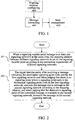
FIG. 2 is a flow diagram of method for transmitting information across signaling networks. - In the embodiment, the system for implementing the message interaction across network types includes a signaling transfer point belonging to more than one signaling networks at the same time. As shown in
FIG. 1 , the signaling transfer point includes a mapping relation configuring unit, a message forwarding unit and a state management unit;
the mapping relation configuring unit is configured to store the mapping relation set by user between different signaling networks according to the interaction requirement of different signaling networks; when the signaling network to which the signaling transfer point belongs includes a first signaling network and a second signaling network, the mapping relation refers to the corresponding relation of the network types of the first signaling network and the second signaling network, or the corresponding relation of the network types of the first signaling network and the second signaling network and the corresponding relation of signaling point codes. - The message forwarding unit is configured to, after receiving a message indicating a destination signaling point code sent by the first signaling network and when judging that there is no signaling point where the signaling point code is the destination signaling point code in the first signaling network, convert the message into a message in the second signaling network according to the mapping relation, and when judging that the destination signaling point of the converted message is available in the second signaling network, forward the message in the second signaling network.
- The way that the message forwarding unit processes the data message, the destination state audit message and the signaling point congestion message sent by the first signaling network is the same with the description in the following methods.
- The state management unit is configured to maintain the states of the signaling transfer points between different signaling networks; specifically, when receiving the office direction available message, update the state of the signaling transfer point as the office direction available state; when receiving the office direction unavailable message, update the state of the signaling transfer point as the office direction unavailable state; and is configured to, when receiving the signaling point congestion (SCON) message, update the state of the signaling transfer point as the congestion state.
Embodiment:
as shown inFIG. 2 , the method for transmitting information across the signaling networks includes the following steps: -
step 201, when a signaling transfer point belongs to more than one signaling networks at the same time, mapping relation between different signaling networks is set on the signaling transfer point according to the interaction requirement of different signaling networks; - the network types of different signaling networks are different, and the network type of the signaling network can be represented by the network appearance. The signaling points in different signaling networks can have the same signaling point code. The mapping relation can include the corresponding relation of the network types of different signaling networks, or also include the corresponding relation of the signaling point codes of different signaling networks.
- The mapping relation on the signaling transfer point is set according to the requirement of communication between different signaling networks. When the communication between different signaling networks requires converting the network type, the corresponding relation of network types of different signaling networks is set. When the communication between different signaling networks also requires converting the signaling point code except for converting the network type, the corresponding relation of the signaling point codes is set except that the corresponding relation of the network types is set.
- There are many ways for implementing the mapping relation, which includes the simple way of the corresponding table, or the way of the database table, or the mapping algorithm, such as Hash algorithm, etc.
step 202, the signal transfer point, after receiving a message indicating the destination signaling point code sent by the first signaling network (that is, the incoming signaling network, the network from which the message received by the IPSTP is) and when judging that there is no signaling point where the signaling point code is the destination signaling point code in the first signaling network, converts the message into a message in the second signaling network (that is, the outgoing signaling network, the destination network to which the message received by the IPSTP is to be transmitted) according to the mapping relation, and when judging that the destination signaling point of the converted message is available in the second signaling network, forwards the message in the second signaling network. - The above methods are described in detail through the service flow and the management flow hereafter.
- Specific Embodiment 1:
- the specific embodiment is used for describing the forwarding flow of the data message on the IPSTP. The signaling transfer point belongs to the first signaling network and the second signaling network at the same time, and the mapping relation configured on the IPSTP includes the corresponding relation of network types of the first signaling network and the second signaling network;
- step 301, the signaling transfer point receives the data message sent by the incoming network (that is the first signaling network, represented as net1), and the message carries the network appearance of the first signaling network (netl) and the signaling point code of the destination signaling point (spc1);
- step 302, the signaling transfer point judges that no corresponding office direction is configured in the first signaling network, that is, there is no signaling point where the signaling point code is spc1 in the first signaling network;
- step 303, the signaling transfer point converts the destination signaling point code (spc1) in the first signaling network (netl) in the message into the destination signaling point code (spc1) in the second signaling network (net2) according to the set mapping relation;
- step 304, the message routing selection is performed in the second signaling network after the converting is finished; if the routing selection succeeds, that is, there is a signaling point where the signaling point code is spc1 in the second signaling network and the signaling point is available in the second signaling network, forward the message outgoing and finish forwarding the message; or else, proceed to the step 305.
- Step 305, if the office direction is available (that is, the converted signaling point code is available in the second signaling network) while the remote user is not available, and the resource signaling point is a direct office, then the opposite end destination user part unavailable (DUPU) message is returned because the remote user is unavailable; the influenced signaling point code is spc1 and the network appearance is net2; if the office direction (net1+spc1) is not available, then the opposite end destination unavailable (DUNA) message is returned, and the influenced signaling point code is spc1 and the network appearance is net2.
- Specific Embodiment 2:
- the specific embodiment is used for describing the forwarding flow of the destination state audit (DAUD) message on the IPSTP. The signaling transfer point belongs to the first signaling network and the second signaling network at the same time; the mapping relation configured on the IPSTP includes the corresponding relation of network types of the first signaling network and the second signaling network.
- Step 401, the signaling transfer point receives the DAUD message where the influenced signaling point code is spc1 in the first signaling network (net1);
- step 402, the signaling transfer point judges that there is no adjacent office where the signaling point code is configured as spc1 in the first signaling network;
- step 403, the signaling transfer point converts the spc1 in the first signaling network (netl) into the spc1 in the second signaling network (net2) according to the set mapping relation;
- step 404, after the converting is finished, if there is a signaling point where the signaling point code is the destination signaling point code in the second signaling network, then the state of the signaling point where the signaling point code is the spc1 in the second signaling network is judged; when the signaling point is in the office direction available state, forward the message in the second signaling network and return the office direction available message to the first signaling network; when the signaling point is in the office direction unavailable state, return the office direction unavailable message to the first signaling network; when the signaling point is in the congestion state, return the signaling point congestion (SCON) message to the first signaling network.
- Specific Embodiment 3:
- the specific embodiment is used for describing the forwarding flow of the SCON message on the IPSTP. The signaling transfer point belongs to the first signaling network and the second signaling network at the same time, and the mapping relation configured on the IPSTP includes the corresponding relation of network types of the first signaling network and the second signaling network.
- Step 501, the signaling transfer point receives the SCON message where the concerned signaling point (concerned destination) is the spc1 in the first signaling network (net1);
- step 502, the signaling transfer point judges that there is no adjacent office where the point code is configured as the spc1 in the first signaling network;
- step 503, the signaling transfer point converts the spc1 in the first signaling network (netl) into the spc1 in the second signaling network (net2) according to the set mapping relation;
- step 504, the message routing selection is performed in the second signaling network after the converting is finished, and the message is forwarded to the signaling point where the signaling point code is the spc1.
- Specific Embodiment 4:
- the specific embodiment is used for describing the forwarding flow of the data message on the IPSTP. The signaling transfer point belongs to the first signaling network and the second signaling network at the same time, and the mapping relation configured on the IPSTP includes the corresponding relation of network types of the first signaling network and the second signaling network and the corresponding relation of the signaling point codes;
- step 601, the signaling transfer point receives the data message sent by the incoming network (that is the first signaling network, represented as net1), and the message carries the network type of the first signaling network (netl) and the signaling point code of the destination signaling point (spc1);
- step 602, the signaling transfer point does not configure the corresponding office direction in the first signaling network, that is, there is no signaling point where the signaling point code is the spc1 in the first signaling network, and the message cannot be forwarded;
- step 603, the signaling transfer point converts the destination signaling point code (spc1) in the first signaling network (netl) in the message into the destination signaling point code (spc2) in the second signaling network (net2) according to the set mapping relation;
- step 604, the message routing selection is performed in the second signaling network after the converting is finished; if the routing selection succeeds, forward the message outgoing and finish forwarding the message; or else, return the DUNA or DUPU message to the opposite end.
- In the above system and method, through setting the mapping relation between different signaling networks on the signaling transfer point, in the case of keeping the existing signaling configuration, the message interaction and the signaling network management are implemented in different signaling networks which cannot intercommunicate originally.
- The above description is only the preferred embodiments of the present invention and is not intended to limit the present invention. For those skilled in the art, the present invention can have various modifications and variations. And all of these modifications, equivalent replacements or the improvements and so on without departing from the scope of the appended claims should be included in the protection scope of the present invention.
- When a plurality of signaling networks are interconnected and in the case of keeping the existing signaling configuration, the present invention set the mapping relation between different signaling networks on the signaling transfer point, and the message interaction and the signaling network management are implemented in different signaling networks which cannot intercommunicate originally.
Claims (14)
- A method for transmitting information across networks, characterized by comprising:when a signaling transfer point belongs to more than one signaling network at the same time, setting (201) a mapping relation between different signaling networks on the signaling transfer point according to an interaction requirement of said different signaling networks;wherein the more than one signaling network to which the signaling transfer point belongs comprise a first signaling network and a second signaling network, and the mapping relation comprises a corresponding relation of network appearances of the first signaling network and the second signaling network and a corresponding relation of signaling point codes of the first signaling network and the second signaling network, andafter receiving a message indicating a destination signaling point code sent by the first signaling network, and when judging that in the first signaling network there is no signaling point whose signaling point code is the destination signaling point code, the signaling transfer point converting (202) the message into a message in the second signaling network according to the mapping relation, wherein the step of converting the message into the message in the second signaling network according to the mapping relation comprises: converting the destination signaling point code indicated by the message sent by the first signaling network into the destination signaling point code in the second signaling network according to the mapping relation; andforwarding (202) the message in the second signaling network when in the second signaling network there is a signaling point whose signaling point code is the destination signaling point code and the signaling point is available in the second signaling network, which means that a state of the signaling point is office direction available.
- The method according to claim 1, wherein
the step of converting the message into the message in the second signaling network according to the mapping relation comprises: the signaling transfer point, after receiving a destination state audit message carrying the destination signaling point code sent by the first signaling network and when judging that in the first signaling network no adjacent office whose signaling point code is the destination signaling point code is configured, converting the destination signaling point code indicated by the message sent by the first signaling network into the destination signaling point code in the second signaling network according to the mapping relation. - The method according to claim 2, further comprising:
the signaling transfer point, when judging that in the second signaling network there is the signaling point whose signaling point code is the destination signaling point code and judging that the state of the signaling point is an office direction unavailable state, returning an office direction unavailable message to the first signaling network; when judging that the state of the signaling point is a congestion state, returning a signaling point congestion message to the first signaling network. - The method according to claim 1, wherein
the step of converting the message into the message in the second signaling network according to the mapping relation comprises: the signaling transfer point, after receiving a signaling point congestion message carrying the destination signaling point code sent by the first signaling network and when judging that in the first signaling network no adjacent office whose signaling point code is the destination signaling point code is configured, converting the destination signaling point code indicated by the message sent by the first signaling network into the destination signaling point code in the second signaling network according to the mapping relation. - A system for implementing message interaction across network appearances, characterized by comprising
a signaling transfer point belonging to more than one signaling network at the same time, the signaling transfer point comprising a mapping relation configuring unit and a message forwarding unit; wherein
the mapping relation configuring unit is configured to set a mapping relation between different signaling networks on the signaling transfer point according to an interaction requirement of said different signaling networks, wherein the more than one signaling network to which the signaling transfer point belongs comprise a first signaling network and a second signaling network and the mapping relation comprises a corresponding relation of network appearances of the first signaling network and the second signaling network and a corresponding relation of signaling point codes of the first signaling network and the second signaling network;
the message forwarding unit is configured to: after receiving a message indicating a destination signaling point code sent by a first signaling network and when judging that in the first signaling network there is no signaling point whose signaling point code is the destination signaling point code, convert the message into a message in a second signaling network according to the mapping relation, and forward the message in the second signaling network when in the second signaling network there is a signaling point whose signaling point code is the destination signaling point code and the signaling point is available in the second signaling network, which means that a state of the signaling point is office direction available, wherein the message forwarding unit is configured to convert the message into the message in the second signaling network according to the mapping relation by a following way: converting the destination signaling point code indicated by the message sent by the first signaling network into the destination signaling point code in the second signaling network according to the mapping relation. - The system according to claim 5, wherein
the message forwarding unit is configured to: after receiving a destination state audit message carrying the destination signaling point code sent by the first signaling network and when judging that in the first signaling network no adjacent office whose signaling point code is the destination signaling point code is configured, convert the destination signaling point code indicated by the message sent by the first signaling network into the destination signaling point code in the second signaling network according to the mapping relation, and forward the message in the second signaling network when in the second signaling network there is a signaling point whose signaling point code is the destination signaling point code and the state of the signaling point is office direction available. - The system according to claim 6, wherein
the message forwarding unit is further configured to: when judging that in the second signaling network there is the signaling point whose signaling point code is the destination signaling point code and judging that the state of the signaling point is an office direction unavailable state, return an office direction unavailable message to the first signaling network; when judging that the state of the signaling point is a congestion state, return a signaling point congestion message to the first signaling network. - The system according to claim 5, wherein
the message forwarding unit is configured to convert the message into the message in the second signaling network according to the mapping relation by a following way: after receiving a signaling point congestion message carrying the destination signaling point code sent by the first signaling network and when judging that in the first signaling network no adjacent office whose signaling point code is the destination signaling point code is configured, converting the destination signaling point code indicated by the message sent by the first signaling network into the destination signaling point code in the second signaling network according to the mapping relation. - The system according to claim 8, wherein
the signaling transfer point further comprises a state management unit, and the state management unit is configured to maintain states of the signaling transfer points between different signaling networks. - The system according to claim 8, wherein
the state management unit is configured to: when receiving an office direction available message, update the state of the signaling transfer point as an office direction available state; when receiving an office direction unavailable message, update the state of the signaling transfer point as an office direction unavailable state; when receiving the signaling point congestion message, update the state of the signaling transfer point as a congestion state. - A signaling transfer point, characterized in that the signaling transfer point belongs to more than one signaling network at the same time, and the signaling transfer point comprises:a mapping relation configuring unit, configured to set a mapping relation between different signaling networks on the signaling transfer point according to an interaction requirement of said different signaling networks, wherein the more than one signaling network to which the signaling transfer point belongs comprise a first signaling network and a second signaling network and the mapping relation comprises a corresponding relation of network appearances of the first signaling network and the second signaling network and a corresponding relation of signaling point codes of the first signaling network and the second signaling network; anda message forwarding unit, configured to: after receiving a message indicating a destination signaling point code sent by a first signaling network and when judging that in the first signaling network there is no signaling point whose signaling point code is the destination signaling point code, convert the message into a message in a second signaling network according to the mapping relation, and forward the message in the second signaling network when in the second signaling network there is a signaling point whose signaling point code is the destination signaling point code and the signaling point is available in the second signaling network, which means that a state of the signaling point is office direction available (202), wherein the message forwarding unit is configured to convert the message into the message in the second signaling network according to the mapping relation by a following way: converting the destination signaling point code indicated by the message sent by the first signaling network into the destination signaling point code in the second signaling network according to the mapping relation.
- The signaling transfer point according to claim 11, wherein
the message forwarding unit is configured to: after receiving a destination state audit message carrying the destination signaling point code sent by the first signaling network and when judging that in the first signaling network no adjacent office whose signaling point code is the destination signaling point code is configured, convert the destination signaling point code indicated by the message sent by the first signaling network into the destination signaling point code in the second signaling network according to the mapping relation, and forward the message in the second signaling network when in the second signaling network there is a signaling point whose signaling point code is the destination signaling point code and the state of the signaling point is office direction available. - The signaling transfer point according to claim 12, wherein
the message forwarding unit is further configured to: when judging that in the second signaling network there is the signaling point whose signaling point code is the destination signaling point code and judging that the state of the signaling point is an office direction unavailable state, return an office direction unavailable message to the first signaling network; when judging that the state of the signaling point is a congestion state, return a signaling point congestion message to the first signaling network. - The signaling transfer point according to claim 13, further comprising:
a state management unit, configured to maintain states of the signaling transfer points between different signaling networks.
Applications Claiming Priority (2)
| Application Number | Priority Date | Filing Date | Title |
|---|---|---|---|
| CN200910171290.5A CN102006523B (en) | 2009-09-03 | 2009-09-03 | Method and system for sending information among signaling networks |
| PCT/CN2010/073142 WO2011026352A1 (en) | 2009-09-03 | 2010-05-24 | Method, system and apparatus for transmitting information across signaling networks |
Publications (3)
| Publication Number | Publication Date |
|---|---|
| EP2456149A1 EP2456149A1 (en) | 2012-05-23 |
| EP2456149A4 EP2456149A4 (en) | 2017-01-11 |
| EP2456149B1 true EP2456149B1 (en) | 2019-07-03 |
Family
ID=43648865
Family Applications (1)
| Application Number | Title | Priority Date | Filing Date |
|---|---|---|---|
| EP10813274.7A Active EP2456149B1 (en) | 2009-09-03 | 2010-05-24 | Method, system and apparatus for transmitting information across signaling networks |
Country Status (5)
| Country | Link |
|---|---|
| US (1) | US20120151076A1 (en) |
| EP (1) | EP2456149B1 (en) |
| CN (1) | CN102006523B (en) |
| IN (1) | IN2012DN01266A (en) |
| WO (1) | WO2011026352A1 (en) |
Families Citing this family (1)
| Publication number | Priority date | Publication date | Assignee | Title |
|---|---|---|---|---|
| US10890068B2 (en) | 2018-12-15 | 2021-01-12 | Jefferson David McKenzie | Automated support of a gate entry for underground full extraction mining |
Citations (3)
| Publication number | Priority date | Publication date | Assignee | Title |
|---|---|---|---|---|
| WO2007019782A1 (en) * | 2005-08-17 | 2007-02-22 | Huawei Technologies Co., Ltd. | Method for transferring the signaling network management message |
| US20070066326A1 (en) * | 2005-09-20 | 2007-03-22 | Tekelec | Methods, systems, and computer program products for facilitating delivery of messaging service messages between domains of different type |
| EP1777970A1 (en) * | 2005-10-21 | 2007-04-25 | Hewlett-Packard Development Company, L.P. | Distinguishing between network entities having the same address |
Family Cites Families (19)
| Publication number | Priority date | Publication date | Assignee | Title |
|---|---|---|---|---|
| JP2555907B2 (en) * | 1990-05-23 | 1996-11-20 | 日本電気株式会社 | Complex network address routing control system |
| US5852660A (en) * | 1996-04-10 | 1998-12-22 | Ericsson Inc. | Network protocol conversion module within a telecommunications system |
| US5867788A (en) * | 1996-06-03 | 1999-02-02 | Ericsson Inc. | Coverting a routing address within a telecommunications network |
| US6944184B1 (en) * | 1998-12-04 | 2005-09-13 | Tekelec | Methods and systems for providing database node access control functionality in a communications network routing node |
| US6411632B2 (en) * | 1997-09-16 | 2002-06-25 | Telefonaktiebolaget Lm Ericsson (Publ) | Network hub for interconnecting a wireless office environment with a public cellular telephone network |
| KR100331468B1 (en) * | 1999-12-16 | 2002-04-09 | 서평원 | method for translation type mapping in No.7 gateway signaling network |
| FI20002093A (en) * | 2000-09-22 | 2002-03-23 | Nokia Corp | Transferring Address Information in the Protocol Stack |
| EP1402669A4 (en) * | 2001-06-05 | 2007-12-26 | Tekelec Us | Methods and systems for communicating signaling information using a normalized signaling protocol |
| US7054328B2 (en) * | 2001-07-23 | 2006-05-30 | Telefonaktiebolaget Lm Ericsson (Publ) | Signal transfer point with internet protocol capability within a telecommunications network |
| US7222192B2 (en) * | 2002-01-10 | 2007-05-22 | Tekelec | Methods and systems for providing mobile location management services in a network routing node |
| US7372953B2 (en) * | 2003-05-28 | 2008-05-13 | Tekelec | Methods and systems for default routing in a signaling network |
| WO2005052742A2 (en) * | 2003-11-20 | 2005-06-09 | Tekelec | Signal transfer point with wireless signaling link interface |
| CN1309230C (en) * | 2004-04-06 | 2007-04-04 | 中兴通讯股份有限公司 | System and method for delivery of telecom signalling messages by passing private net boundary |
| US7760708B2 (en) * | 2005-07-08 | 2010-07-20 | Tekelec | Methods, systems, and computer program products for triggering SIP nodes to include SS7 routing information in response messages including information requested by SS7 nodes |
| CN100452781C (en) * | 2005-10-26 | 2009-01-14 | 华为技术有限公司 | Method for transmitting partial unavailable information to destination user |
| CN101052019B (en) * | 2007-04-05 | 2010-10-06 | 华为技术有限公司 | Method for selecting message bearing link and signaling switch point |
| CN101383840B (en) * | 2007-09-05 | 2011-12-21 | 华为技术有限公司 | Network, device and message transmitting method based on M3UA protocol networking |
| KR20090037154A (en) * | 2007-10-11 | 2009-04-15 | 주식회사 케이티프리텔 | Backup method and system for using multiple signaling point |
| US8621103B2 (en) * | 2008-04-22 | 2013-12-31 | Telefonaktiebolaget Lm Ericsson (Publ) | Network node and method of routing messages in an IP-based signaling network |
-
2009
- 2009-09-03 CN CN200910171290.5A patent/CN102006523B/en active Active
-
2010
- 2010-05-24 IN IN1266DEN2012 patent/IN2012DN01266A/en unknown
- 2010-05-24 WO PCT/CN2010/073142 patent/WO2011026352A1/en active Application Filing
- 2010-05-24 EP EP10813274.7A patent/EP2456149B1/en active Active
- 2010-05-24 US US13/389,956 patent/US20120151076A1/en not_active Abandoned
Patent Citations (3)
| Publication number | Priority date | Publication date | Assignee | Title |
|---|---|---|---|---|
| WO2007019782A1 (en) * | 2005-08-17 | 2007-02-22 | Huawei Technologies Co., Ltd. | Method for transferring the signaling network management message |
| US20070066326A1 (en) * | 2005-09-20 | 2007-03-22 | Tekelec | Methods, systems, and computer program products for facilitating delivery of messaging service messages between domains of different type |
| EP1777970A1 (en) * | 2005-10-21 | 2007-04-25 | Hewlett-Packard Development Company, L.P. | Distinguishing between network entities having the same address |
Also Published As
| Publication number | Publication date |
|---|---|
| CN102006523A (en) | 2011-04-06 |
| WO2011026352A1 (en) | 2011-03-10 |
| EP2456149A1 (en) | 2012-05-23 |
| EP2456149A4 (en) | 2017-01-11 |
| IN2012DN01266A (en) | 2015-05-15 |
| CN102006523B (en) | 2014-04-09 |
| US20120151076A1 (en) | 2012-06-14 |
Similar Documents
| Publication | Publication Date | Title |
|---|---|---|
| CN100584053C (en) | Signal transfer point with internet protocol capability within telecom network | |
| EP2279626B1 (en) | Method of operating a signalling gateway and an application server, as well as signalling gateway and application server | |
| CN100379228C (en) | Net gate system and fault management method | |
| CN101411175A (en) | Routing of telecommunications | |
| US20060098628A1 (en) | Methods and apparatus for controlling signaling gateways | |
| CN102209020A (en) | Service routing method, apparatus and system thereof | |
| EP2456149B1 (en) | Method, system and apparatus for transmitting information across signaling networks | |
| US20100040219A1 (en) | Method and apparatus for processing number portability call among various telephone networks | |
| US6845250B1 (en) | Method and system for transmitting messages in a communications network | |
| CN101383840B (en) | Network, device and message transmitting method based on M3UA protocol networking | |
| US7894455B2 (en) | Systems and methods for a signalling gateway for connecting networks | |
| EP1885138B1 (en) | Signalling gateway | |
| EP1492359A1 (en) | Processing of signalling messages according to one of a plurality of protocol stacks | |
| CN101207564B (en) | Method for extending M3UA route supervision function | |
| CN100583833C (en) | Method and device for selecting the signaling route of the different service messages | |
| CN101184047A (en) | Message routing method, equipment and system | |
| KR100511747B1 (en) | Operation Method for Signaling Network Resources in Signaling Gateway System | |
| CN101207616A (en) | Method for extending IP signaling system M3UA route supervising function | |
| CN101207615A (en) | Method for extending M3UA route supervision function | |
| US8156194B2 (en) | Signaling gateway | |
| CN101136845A (en) | Multi-protocol routing configuration device and method | |
| US8762557B2 (en) | Signaling gateway and its signaling processing method | |
| KR100719006B1 (en) | M3ua network with more than one signaling gateway and thereof method for transferring m3ua message | |
| KR100989981B1 (en) | Softswitch implemented one ASP | |
| KR100820854B1 (en) | Home location register system that support network interface of trank line base and ip base |
Legal Events
| Date | Code | Title | Description |
|---|---|---|---|
| PUAI | Public reference made under article 153(3) epc to a published international application that has entered the european phase |
Free format text: ORIGINAL CODE: 0009012 |
|
| 17P | Request for examination filed |
Effective date: 20120217 |
|
| AK | Designated contracting states |
Kind code of ref document: A1 Designated state(s): AL AT BE BG CH CY CZ DE DK EE ES FI FR GB GR HR HU IE IS IT LI LT LU LV MC MK MT NL NO PL PT RO SE SI SK SM TR |
|
| DAX | Request for extension of the european patent (deleted) | ||
| RA4 | Supplementary search report drawn up and despatched (corrected) |
Effective date: 20161212 |
|
| RIC1 | Information provided on ipc code assigned before grant |
Ipc: H04L 12/66 20060101AFI20161206BHEP Ipc: H04L 29/12 20060101ALI20161206BHEP |
|
| STAA | Information on the status of an ep patent application or granted ep patent |
Free format text: STATUS: EXAMINATION IS IN PROGRESS |
|
| 17Q | First examination report despatched |
Effective date: 20180518 |
|
| GRAP | Despatch of communication of intention to grant a patent |
Free format text: ORIGINAL CODE: EPIDOSNIGR1 |
|
| STAA | Information on the status of an ep patent application or granted ep patent |
Free format text: STATUS: GRANT OF PATENT IS INTENDED |
|
| INTG | Intention to grant announced |
Effective date: 20190116 |
|
| GRAS | Grant fee paid |
Free format text: ORIGINAL CODE: EPIDOSNIGR3 |
|
| GRAA | (expected) grant |
Free format text: ORIGINAL CODE: 0009210 |
|
| STAA | Information on the status of an ep patent application or granted ep patent |
Free format text: STATUS: THE PATENT HAS BEEN GRANTED |
|
| AK | Designated contracting states |
Kind code of ref document: B1 Designated state(s): AL AT BE BG CH CY CZ DE DK EE ES FI FR GB GR HR HU IE IS IT LI LT LU LV MC MK MT NL NO PL PT RO SE SI SK SM TR |
|
| REG | Reference to a national code |
Ref country code: GB Ref legal event code: FG4D |
|
| REG | Reference to a national code |
Ref country code: CH Ref legal event code: EP Ref country code: AT Ref legal event code: REF Ref document number: 1152322 Country of ref document: AT Kind code of ref document: T Effective date: 20190715 |
|
| REG | Reference to a national code |
Ref country code: IE Ref legal event code: FG4D |
|
| REG | Reference to a national code |
Ref country code: DE Ref legal event code: R096 Ref document number: 602010059876 Country of ref document: DE |
|
| REG | Reference to a national code |
Ref country code: NL Ref legal event code: MP Effective date: 20190703 |
|
| REG | Reference to a national code |
Ref country code: LT Ref legal event code: MG4D |
|
| REG | Reference to a national code |
Ref country code: AT Ref legal event code: MK05 Ref document number: 1152322 Country of ref document: AT Kind code of ref document: T Effective date: 20190703 |
|
| PG25 | Lapsed in a contracting state [announced via postgrant information from national office to epo] |
Ref country code: LT Free format text: LAPSE BECAUSE OF FAILURE TO SUBMIT A TRANSLATION OF THE DESCRIPTION OR TO PAY THE FEE WITHIN THE PRESCRIBED TIME-LIMIT Effective date: 20190703 Ref country code: NO Free format text: LAPSE BECAUSE OF FAILURE TO SUBMIT A TRANSLATION OF THE DESCRIPTION OR TO PAY THE FEE WITHIN THE PRESCRIBED TIME-LIMIT Effective date: 20191003 Ref country code: HR Free format text: LAPSE BECAUSE OF FAILURE TO SUBMIT A TRANSLATION OF THE DESCRIPTION OR TO PAY THE FEE WITHIN THE PRESCRIBED TIME-LIMIT Effective date: 20190703 Ref country code: AT Free format text: LAPSE BECAUSE OF FAILURE TO SUBMIT A TRANSLATION OF THE DESCRIPTION OR TO PAY THE FEE WITHIN THE PRESCRIBED TIME-LIMIT Effective date: 20190703 Ref country code: BG Free format text: LAPSE BECAUSE OF FAILURE TO SUBMIT A TRANSLATION OF THE DESCRIPTION OR TO PAY THE FEE WITHIN THE PRESCRIBED TIME-LIMIT Effective date: 20191003 Ref country code: PT Free format text: LAPSE BECAUSE OF FAILURE TO SUBMIT A TRANSLATION OF THE DESCRIPTION OR TO PAY THE FEE WITHIN THE PRESCRIBED TIME-LIMIT Effective date: 20191104 Ref country code: NL Free format text: LAPSE BECAUSE OF FAILURE TO SUBMIT A TRANSLATION OF THE DESCRIPTION OR TO PAY THE FEE WITHIN THE PRESCRIBED TIME-LIMIT Effective date: 20190703 Ref country code: CZ Free format text: LAPSE BECAUSE OF FAILURE TO SUBMIT A TRANSLATION OF THE DESCRIPTION OR TO PAY THE FEE WITHIN THE PRESCRIBED TIME-LIMIT Effective date: 20190703 Ref country code: FI Free format text: LAPSE BECAUSE OF FAILURE TO SUBMIT A TRANSLATION OF THE DESCRIPTION OR TO PAY THE FEE WITHIN THE PRESCRIBED TIME-LIMIT Effective date: 20190703 Ref country code: SE Free format text: LAPSE BECAUSE OF FAILURE TO SUBMIT A TRANSLATION OF THE DESCRIPTION OR TO PAY THE FEE WITHIN THE PRESCRIBED TIME-LIMIT Effective date: 20190703 |
|
| PG25 | Lapsed in a contracting state [announced via postgrant information from national office to epo] |
Ref country code: IS Free format text: LAPSE BECAUSE OF FAILURE TO SUBMIT A TRANSLATION OF THE DESCRIPTION OR TO PAY THE FEE WITHIN THE PRESCRIBED TIME-LIMIT Effective date: 20191103 Ref country code: LV Free format text: LAPSE BECAUSE OF FAILURE TO SUBMIT A TRANSLATION OF THE DESCRIPTION OR TO PAY THE FEE WITHIN THE PRESCRIBED TIME-LIMIT Effective date: 20190703 Ref country code: GR Free format text: LAPSE BECAUSE OF FAILURE TO SUBMIT A TRANSLATION OF THE DESCRIPTION OR TO PAY THE FEE WITHIN THE PRESCRIBED TIME-LIMIT Effective date: 20191004 Ref country code: ES Free format text: LAPSE BECAUSE OF FAILURE TO SUBMIT A TRANSLATION OF THE DESCRIPTION OR TO PAY THE FEE WITHIN THE PRESCRIBED TIME-LIMIT Effective date: 20190703 Ref country code: AL Free format text: LAPSE BECAUSE OF FAILURE TO SUBMIT A TRANSLATION OF THE DESCRIPTION OR TO PAY THE FEE WITHIN THE PRESCRIBED TIME-LIMIT Effective date: 20190703 |
|
| PG25 | Lapsed in a contracting state [announced via postgrant information from national office to epo] |
Ref country code: TR Free format text: LAPSE BECAUSE OF FAILURE TO SUBMIT A TRANSLATION OF THE DESCRIPTION OR TO PAY THE FEE WITHIN THE PRESCRIBED TIME-LIMIT Effective date: 20190703 |
|
| PG25 | Lapsed in a contracting state [announced via postgrant information from national office to epo] |
Ref country code: EE Free format text: LAPSE BECAUSE OF FAILURE TO SUBMIT A TRANSLATION OF THE DESCRIPTION OR TO PAY THE FEE WITHIN THE PRESCRIBED TIME-LIMIT Effective date: 20190703 Ref country code: DK Free format text: LAPSE BECAUSE OF FAILURE TO SUBMIT A TRANSLATION OF THE DESCRIPTION OR TO PAY THE FEE WITHIN THE PRESCRIBED TIME-LIMIT Effective date: 20190703 Ref country code: IT Free format text: LAPSE BECAUSE OF FAILURE TO SUBMIT A TRANSLATION OF THE DESCRIPTION OR TO PAY THE FEE WITHIN THE PRESCRIBED TIME-LIMIT Effective date: 20190703 Ref country code: RO Free format text: LAPSE BECAUSE OF FAILURE TO SUBMIT A TRANSLATION OF THE DESCRIPTION OR TO PAY THE FEE WITHIN THE PRESCRIBED TIME-LIMIT Effective date: 20190703 Ref country code: PL Free format text: LAPSE BECAUSE OF FAILURE TO SUBMIT A TRANSLATION OF THE DESCRIPTION OR TO PAY THE FEE WITHIN THE PRESCRIBED TIME-LIMIT Effective date: 20190703 |
|
| PG25 | Lapsed in a contracting state [announced via postgrant information from national office to epo] |
Ref country code: SK Free format text: LAPSE BECAUSE OF FAILURE TO SUBMIT A TRANSLATION OF THE DESCRIPTION OR TO PAY THE FEE WITHIN THE PRESCRIBED TIME-LIMIT Effective date: 20190703 Ref country code: IS Free format text: LAPSE BECAUSE OF FAILURE TO SUBMIT A TRANSLATION OF THE DESCRIPTION OR TO PAY THE FEE WITHIN THE PRESCRIBED TIME-LIMIT Effective date: 20200224 Ref country code: SM Free format text: LAPSE BECAUSE OF FAILURE TO SUBMIT A TRANSLATION OF THE DESCRIPTION OR TO PAY THE FEE WITHIN THE PRESCRIBED TIME-LIMIT Effective date: 20190703 |
|
| REG | Reference to a national code |
Ref country code: DE Ref legal event code: R097 Ref document number: 602010059876 Country of ref document: DE |
|
| PLBE | No opposition filed within time limit |
Free format text: ORIGINAL CODE: 0009261 |
|
| STAA | Information on the status of an ep patent application or granted ep patent |
Free format text: STATUS: NO OPPOSITION FILED WITHIN TIME LIMIT |
|
| PG2D | Information on lapse in contracting state deleted |
Ref country code: IS |
|
| 26N | No opposition filed |
Effective date: 20200603 |
|
| PG25 | Lapsed in a contracting state [announced via postgrant information from national office to epo] |
Ref country code: SI Free format text: LAPSE BECAUSE OF FAILURE TO SUBMIT A TRANSLATION OF THE DESCRIPTION OR TO PAY THE FEE WITHIN THE PRESCRIBED TIME-LIMIT Effective date: 20190703 |
|
| PG25 | Lapsed in a contracting state [announced via postgrant information from national office to epo] |
Ref country code: MC Free format text: LAPSE BECAUSE OF FAILURE TO SUBMIT A TRANSLATION OF THE DESCRIPTION OR TO PAY THE FEE WITHIN THE PRESCRIBED TIME-LIMIT Effective date: 20190703 Ref country code: LI Free format text: LAPSE BECAUSE OF NON-PAYMENT OF DUE FEES Effective date: 20200531 Ref country code: CH Free format text: LAPSE BECAUSE OF NON-PAYMENT OF DUE FEES Effective date: 20200531 |
|
| REG | Reference to a national code |
Ref country code: BE Ref legal event code: MM Effective date: 20200531 |
|
| GBPC | Gb: european patent ceased through non-payment of renewal fee |
Effective date: 20200524 |
|
| PG25 | Lapsed in a contracting state [announced via postgrant information from national office to epo] |
Ref country code: LU Free format text: LAPSE BECAUSE OF NON-PAYMENT OF DUE FEES Effective date: 20200524 |
|
| PG25 | Lapsed in a contracting state [announced via postgrant information from national office to epo] |
Ref country code: GB Free format text: LAPSE BECAUSE OF NON-PAYMENT OF DUE FEES Effective date: 20200524 Ref country code: IE Free format text: LAPSE BECAUSE OF NON-PAYMENT OF DUE FEES Effective date: 20200524 |
|
| PG25 | Lapsed in a contracting state [announced via postgrant information from national office to epo] |
Ref country code: BE Free format text: LAPSE BECAUSE OF NON-PAYMENT OF DUE FEES Effective date: 20200531 |
|
| PG25 | Lapsed in a contracting state [announced via postgrant information from national office to epo] |
Ref country code: MT Free format text: LAPSE BECAUSE OF FAILURE TO SUBMIT A TRANSLATION OF THE DESCRIPTION OR TO PAY THE FEE WITHIN THE PRESCRIBED TIME-LIMIT Effective date: 20190703 Ref country code: CY Free format text: LAPSE BECAUSE OF FAILURE TO SUBMIT A TRANSLATION OF THE DESCRIPTION OR TO PAY THE FEE WITHIN THE PRESCRIBED TIME-LIMIT Effective date: 20190703 |
|
| PG25 | Lapsed in a contracting state [announced via postgrant information from national office to epo] |
Ref country code: MK Free format text: LAPSE BECAUSE OF FAILURE TO SUBMIT A TRANSLATION OF THE DESCRIPTION OR TO PAY THE FEE WITHIN THE PRESCRIBED TIME-LIMIT Effective date: 20190703 |
|
| REG | Reference to a national code |
Ref country code: FR Ref legal event code: PLFP Year of fee payment: 14 |
|
| PGFP | Annual fee paid to national office [announced via postgrant information from national office to epo] |
Ref country code: FR Payment date: 20230411 Year of fee payment: 14 Ref country code: DE Payment date: 20230331 Year of fee payment: 14 |