EP2456004A1 - Battery pack device - Google Patents
Battery pack device Download PDFInfo
- Publication number
- EP2456004A1 EP2456004A1 EP20110179201 EP11179201A EP2456004A1 EP 2456004 A1 EP2456004 A1 EP 2456004A1 EP 20110179201 EP20110179201 EP 20110179201 EP 11179201 A EP11179201 A EP 11179201A EP 2456004 A1 EP2456004 A1 EP 2456004A1
- Authority
- EP
- European Patent Office
- Prior art keywords
- battery
- casing
- battery pack
- pack device
- air
- Prior art date
- Legal status (The legal status is an assumption and is not a legal conclusion. Google has not performed a legal analysis and makes no representation as to the accuracy of the status listed.)
- Withdrawn
Links
Images


Classifications
-
- H—ELECTRICITY
- H01—ELECTRIC ELEMENTS
- H01M—PROCESSES OR MEANS, e.g. BATTERIES, FOR THE DIRECT CONVERSION OF CHEMICAL ENERGY INTO ELECTRICAL ENERGY
- H01M50/00—Constructional details or processes of manufacture of the non-active parts of electrochemical cells other than fuel cells, e.g. hybrid cells
- H01M50/30—Arrangements for facilitating escape of gases
-
- H—ELECTRICITY
- H01—ELECTRIC ELEMENTS
- H01M—PROCESSES OR MEANS, e.g. BATTERIES, FOR THE DIRECT CONVERSION OF CHEMICAL ENERGY INTO ELECTRICAL ENERGY
- H01M10/00—Secondary cells; Manufacture thereof
- H01M10/60—Heating or cooling; Temperature control
-
- H—ELECTRICITY
- H01—ELECTRIC ELEMENTS
- H01M—PROCESSES OR MEANS, e.g. BATTERIES, FOR THE DIRECT CONVERSION OF CHEMICAL ENERGY INTO ELECTRICAL ENERGY
- H01M10/00—Secondary cells; Manufacture thereof
- H01M10/60—Heating or cooling; Temperature control
- H01M10/61—Types of temperature control
- H01M10/613—Cooling or keeping cold
-
- H—ELECTRICITY
- H01—ELECTRIC ELEMENTS
- H01M—PROCESSES OR MEANS, e.g. BATTERIES, FOR THE DIRECT CONVERSION OF CHEMICAL ENERGY INTO ELECTRICAL ENERGY
- H01M10/00—Secondary cells; Manufacture thereof
- H01M10/60—Heating or cooling; Temperature control
- H01M10/64—Heating or cooling; Temperature control characterised by the shape of the cells
- H01M10/647—Prismatic or flat cells, e.g. pouch cells
-
- H—ELECTRICITY
- H01—ELECTRIC ELEMENTS
- H01M—PROCESSES OR MEANS, e.g. BATTERIES, FOR THE DIRECT CONVERSION OF CHEMICAL ENERGY INTO ELECTRICAL ENERGY
- H01M10/00—Secondary cells; Manufacture thereof
- H01M10/60—Heating or cooling; Temperature control
- H01M10/65—Means for temperature control structurally associated with the cells
- H01M10/655—Solid structures for heat exchange or heat conduction
- H01M10/6556—Solid parts with flow channel passages or pipes for heat exchange
- H01M10/6557—Solid parts with flow channel passages or pipes for heat exchange arranged between the cells
-
- H—ELECTRICITY
- H01—ELECTRIC ELEMENTS
- H01M—PROCESSES OR MEANS, e.g. BATTERIES, FOR THE DIRECT CONVERSION OF CHEMICAL ENERGY INTO ELECTRICAL ENERGY
- H01M10/00—Secondary cells; Manufacture thereof
- H01M10/60—Heating or cooling; Temperature control
- H01M10/65—Means for temperature control structurally associated with the cells
- H01M10/656—Means for temperature control structurally associated with the cells characterised by the type of heat-exchange fluid
- H01M10/6561—Gases
- H01M10/6562—Gases with free flow by convection only
-
- H—ELECTRICITY
- H01—ELECTRIC ELEMENTS
- H01M—PROCESSES OR MEANS, e.g. BATTERIES, FOR THE DIRECT CONVERSION OF CHEMICAL ENERGY INTO ELECTRICAL ENERGY
- H01M50/00—Constructional details or processes of manufacture of the non-active parts of electrochemical cells other than fuel cells, e.g. hybrid cells
- H01M50/10—Primary casings; Jackets or wrappings
-
- H—ELECTRICITY
- H01—ELECTRIC ELEMENTS
- H01M—PROCESSES OR MEANS, e.g. BATTERIES, FOR THE DIRECT CONVERSION OF CHEMICAL ENERGY INTO ELECTRICAL ENERGY
- H01M50/00—Constructional details or processes of manufacture of the non-active parts of electrochemical cells other than fuel cells, e.g. hybrid cells
- H01M50/20—Mountings; Secondary casings or frames; Racks, modules or packs; Suspension devices; Shock absorbers; Transport or carrying devices; Holders
-
- H—ELECTRICITY
- H01—ELECTRIC ELEMENTS
- H01M—PROCESSES OR MEANS, e.g. BATTERIES, FOR THE DIRECT CONVERSION OF CHEMICAL ENERGY INTO ELECTRICAL ENERGY
- H01M50/00—Constructional details or processes of manufacture of the non-active parts of electrochemical cells other than fuel cells, e.g. hybrid cells
- H01M50/10—Primary casings; Jackets or wrappings
- H01M50/102—Primary casings; Jackets or wrappings characterised by their shape or physical structure
- H01M50/103—Primary casings; Jackets or wrappings characterised by their shape or physical structure prismatic or rectangular
-
- Y—GENERAL TAGGING OF NEW TECHNOLOGICAL DEVELOPMENTS; GENERAL TAGGING OF CROSS-SECTIONAL TECHNOLOGIES SPANNING OVER SEVERAL SECTIONS OF THE IPC; TECHNICAL SUBJECTS COVERED BY FORMER USPC CROSS-REFERENCE ART COLLECTIONS [XRACs] AND DIGESTS
- Y02—TECHNOLOGIES OR APPLICATIONS FOR MITIGATION OR ADAPTATION AGAINST CLIMATE CHANGE
- Y02E—REDUCTION OF GREENHOUSE GAS [GHG] EMISSIONS, RELATED TO ENERGY GENERATION, TRANSMISSION OR DISTRIBUTION
- Y02E60/00—Enabling technologies; Technologies with a potential or indirect contribution to GHG emissions mitigation
- Y02E60/10—Energy storage using batteries
Definitions
- Embodiments described herein relate generally to a battery pack device.
- FIG. 1 is a perspective view schematically showing a battery pack device according to a first embodiment.
- FIG. 2 is a view of the battery pack device in FIG. 1 seen from an air inlet side.
- FIG. 3 is a cross-sectional view of the battery pack device taken along A-A line in FIG. 2 .
- FIG. 4 is a perspective view showing a battery cell included in the battery pack device in FIG. 1 .
- FIG. 5 is a view of another battery pack device, different in structure from the battery pack device in FIG. 1 , seen from an air inlet side.
- FIG. 6 is a view of a battery pack device of a comparative example, seen from an air inlet side.
- FIG. 7 is a cross-sectional view of the battery pack device taken along B-B line in FIG. 6 .
- FIG. 8 is a view of a battery pack device according to a second embodiment seen from an air inlet side.
- FIG. 9 is a cross-sectional view of the battery pack device taken along C-C line in FIG. 8 .
- FIG. 10 is a cross-sectional view showing the structure of a battery pack device according to a third embodiment.
- FIG. 11 is a view on arrow showing the battery pack device seen in the direction of an arrow D in FIG. 10 .
- FIG. 12 is a view of another battery pack device, different in structure from the battery pack device in FIG. 10 , seen from an air inlet side.
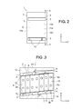
- FIG. 13 is a view of a battery pack device according to a fourth embodiment seen from an air inlet side.
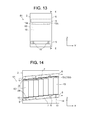
- FIG. 14 is a cross-sectional view of the battery pack device taken along E-E line in FIG. 13 .
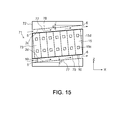
- FIG. 15 is a cross-sectional view showing the structure of a battery pack device according to a fifth embodiment.
- a battery pack device includes a battery module, a casing, an air inlet, an air outlet, and a ventilation channel.
- a battery module a plurality of battery cells stacked one on another are disposed.
- the casing is installed while housing the battery module therein.
- the air inlet is provided in the casing and lets an outside air into the casing.
- the air outlet is provided in the casing, disposed at a position higher than a position of the air inlet, and lets the air out of the casing.
- the ventilation channel in the casing, connects the air inlet and the air outlet, and inclines with respect to a horizontal direction
- a battery pack device 1 is a battery pack device of a fixed type used in ordinary houses, factories, and so on.
- the battery pack device 1 includes a casing 2, a battery module 3, air inlets 5, air outlets 6, ventilation channels (airways) 7, an upper end fixture 8, a lower end fixture 9, stays 10, and control component storages 12, 14.
- the battery cells 15 are each formed in a substantially rectangular parallelepiped shape (thin rectangular box shape) as shown in FIG. 4 .
- the battery cells 15 each have a pair of terminals 15c, 15d projecting from an end surface 15b of a battery cell main body 15a.
- the battery cells 15 are each a secondary battery such as, for example, a lithium-ion battery, a nickel-metal hydride battery, or the like.
- the upper end fixture 8 and the lower end fixture 9 mechanically connect the battery cells 15 to one another.
- the upper end fixture 8 and the lower end fixture 9 integrate and fix the plural stacked battery cells 15 by using, for example, bolts and nuts, with insulating papers or the like interposed between the battery cells 15 or around the battery cells 15.
- the pairs of terminals 15c, 15d of these battery cells 15 are connected to one another via busbars or the like. Consequently, these battery cells 15 are connected to one another in series (or in parallel).
- the plural battery cells 15 which are not only mechanically fixed but also electrically connected to one another are covered by insulating resin such as, for example, polypropylene (PP) from the outside.
- the casing 2 is fixedly installed while housing the battery module 3 with such a structure therein.
- the casing 2 is formed in a rectangular box shape.
- the casing 2 encloses the battery module 3 by its six surfaces, that is, its front surface, rear surface, upper surface, bottom surface, left side surface, and right side surface.
- the control component storages 12, 14 are provided inside an upper casing portion 2a and a lower casing portion 2b of the casing 2.
- various kinds of electronic components such as circuit breakers, plugs, sensors measuring a charge/discharge state, meters, and control boards are provided.
- the stays 10 support the battery module 3 above the lower casing portion 2b of the casing 2.
- the air inlets 5 are formed in a slit shape at two places of one of the side surfaces of the casing 2. These two air inlets 5 let the outside air into the casing 2. Further, the air outlets 6 are provided so as to correspond to the respective two air inlets 5, and are formed in a slit shape at two places of the other side surface of the casing 2. These two air outlets 6 are disposed at positions higher than positions of the corresponding air inlets 5, on the casing 2. These two air outlets 6 let the outside air, which is taken in from the air inlets 5, out of the casing 2.
- the air inlets 5 and the air outlets 6 in the slit shape are formed so that a longitudinal direction of the slit is directed in a horizontal direction (arrow Y direction).
- the ventilation channels 7 extend in the casing 2 from the respective air inlets 5 toward the corresponding air outlets 6 at higher positions in a direction inclined with respect to the horizontal direction. Specifically, the ventilation channels 7 bring the outside air taken in from the air inlets 5 into contact with the battery module 3 that generates heat inside the casing 2. The air heated by this contact is discharged from the air outlets 6 to the outside.
- the battery module 3 is housed in the casing 2, with an arrangement direction of the pair of terminals 15c, 15d on each of the battery cells 15 (width direction of the battery cells), that is, a straight line connecting the terminal 15c and the terminal 15d being directed in a vertical direction (arrow Z direction).
- the battery cells 15 are arranged in a stacked state in a direction from the air inlet 5 side toward the air outlet 6 side.
- the battery cells 15 are disposed so that their positions in the vertical direction become higher stepwise from the air inlet 5 side toward the air outlet 6 side. That is, the upper end fixture 8 and the lower end fixture 9 are each formed in a shape having a plurality of steps.
- the ventilation channels 7 are mainly formed by spaces sandwiched between upper and bottom surfaces of the battery module 3 and the inclined surfaces 2c, 2d. This means that the ventilation channels 7 are formed at positions where the ventilation channels 7 come into contact with at least the upper surface and the bottom surface of the battery module 3 housed in the casing 2.
- a battery pack device 11 in which a plurality of the battery modules 3 arranged side by side along the horizontal direction (arrow Y direction which is a height direction of the battery cells) are housed in a casing 22 as shown in FIG. 5 .
- This battery pack device 11 can also have the same cooling performance as that of the battery pack device 1.
- a battery pack device 21 as a comparative example of the battery pack device 1 and the battery pack device 11 of this embodiment will be exemplified in FIG. 6 and FIG. 7 .
- ventilation channels 27 are flat without being inclined from air inlets 25 toward air outlets 26. Therefore, the air does not easily flow from the air inlet 25 side toward the air outlet side 26 in FIG. 7 . Further, it is highly possible that the outflow and inflow of the air occur only in areas near entrances of both the air inlets 25 and the air outlets 26. Therefore, in the battery pack device 21 of the comparative example, it can be anticipated that performance of cooling a battery module 23 becomes unstable, and in particular, there is a possibility that the vicinity of the center is not cooled.
- the air heated by the heat generation of the battery module 3 in the casing 2 flows from lower sides toward higher sides on the ventilation channels 7 as shown in FIG. 3 . Therefore, the outside air taken in from the air inlets 5, after coming into contact with the surfaces of the battery module 3 in the casing 2, is smoothly discharged to the outside from the air outlets 6. This makes it possible for the battery pack device 1 (and 11) to realize the stable cooling of the battery module 3.
- the inclination angle ⁇ of the inclined surfaces 2c, 2d of the casing 2 shown in FIG. 3 is desirably not less than 4° nor greater than 10°, and 5° is optimum.
- the inclination angle ⁇ is less than 4°, the warmed air becomes stagnant in the course of flowing from the air inlet 5 side toward the air outlet 6 side.
- the inclination angle ⁇ is over 10°, the dense arrangement of various components becomes difficult, even though the flow of the air does not become stagnant. Therefore, in this case, it becomes difficult to improve the energy density of the battery pack device.
- the battery pack devices 1, 11 are each structured so that the upper surface and the bottom surface of the battery module 3 have a plurality of steps as shown in FIG. 3 . Therefore, in the battery pack devices 1, 11, an area of the surfaces of the battery module 3 that come into contact with the outside air practically increases, which makes it possible to obtain a higher cooling effect.
- the air inlets 5 and the air outlets 6 are provided both on the upper surface side and the lower surface side of the battery module 3.
- the air inlet 5 and the air outlet 6 may be provided either on the upper surface side or on the lower surface side. This applies to any of the following embodiments.
- FIG. 8 and FIG. 9 the same constituent elements as those of the first embodiment shown in FIG. 1 to FIG. 3 will be denoted by the same reference numerals and symbols, and a description thereof will be omitted.
- the second embodiment is structured with changes being made to the first embodiment, and only changed structures will be described. Further, in FIG. 8 and FIG. 9 , the illustration of the stays 10 shown in FIG. 2 and FIG. 3 is omitted.
- a battery pack device 31 a plurality of battery modules 3 arranged side by side along a vertical direction (Z direction being a width direction of battery cells) are housed in a casing. Further, in the battery pack device 31, ventilation channels 7 are provided also between the battery modules 3 in the casing. Therefore, a stable cooling effect can be expected also in the battery pack device 31.
- FIG. 10 to FIG. 12 the same constituent elements as those of the first and second embodiments shown in FIG. 1 to FIG. 3 , FIG. 8 , and FIG. 9 are denoted by the same reference numerals and symbols, and a description thereof will be omitted. Note that in FIG. 10 and FIG. 12 , the illustration of the stays 10 shown in FIG. 2 and FIG. 3 is omitted.
- a battery pack device 41 further includes a plurality of ventilation channels (second ventilation channels) 47 formed by gaps in a slit shape between battery cells 15 in a battery module 43.
- These ventilation channels 47 form airflows passing between the battery cells 15 along a vertical direction (Z direction being a width direction of the battery cells) in a casing 2.
- Z direction being a width direction of the battery cells
- the battery pack devices 41, 51 of this embodiment can have a higher effect of cooling the individual battery cells 15 owing to the plural ventilation channels 47 in addition to the ventilation channels 7. As a result, the battery pack devices 41, 51 of this embodiment can realize more stable performance of cooling the battery module 43.
- FIG. 13 and FIG. 14 A fourth embodiment will be described based on FIG. 13 and FIG. 14 .
- the same constituent elements as those of the first to third embodiments shown in FIG. 1 to FIG. 3 and FIG. 8 to FIG. 11 will be denoted by the same reference numerals and symbols, and a description thereof will be omitted.
- a battery module 63 is housed in a casing 2, with a direction in which pairs of terminals 15c, 15d of battery cells 15 project being directed in a vertical direction (Z direction).
- Z direction a vertical direction
- stable performance of cooling the battery module 63 can also be obtained.
- the battery pack device in which a plurality of the battery modules 63 are arranged side by side along the vertical direction (Z direction). Further, it is also possible to form a battery pack device in which a plurality of the battery modules 63 are arranged side by side along the horizontal direction (Y direction being a width direction of the battery cells of this embodiment).
- FIG. 15 A fifth embodiment will be described based on FIG. 15 .
- the same constituent elements as those of the first to fourth embodiments shown in FIG. 1 to FIG. 3 , FIG. 8 to FIG. 11 , FIG. 13, and FIG. 14 will be denoted by the same reference numerals and symbols, and a description thereof will be omitted.
- a battery module 73 or a plurality of battery modules 73 is (are) housed in a casing 72, with a stack direction of battery cells 15 being inclined with respect to a horizontal direction (arrow X direction).
- an upper surface and a bottom surface of the battery module 73 can be flat surfaces without any step shown in FIG. 3 . Therefore, in the battery pack device 71, the stagnation or the like of the air passing through ventilation channels 77 is not likely to occur. Consequently, a good heat removal effect for the battery module 73 can be expected in the battery pack device 71.
- the upper surface and the bottom surface of the battery module 73 can be flat surfaces. This can simplify the shape of an upper end fixture 78 and a lower end fixture 79 in the battery pack device 71, enabling higher productivity of the battery pack device itself.
- the battery module 73 in which the stack direction of the battery cells 15 is inclined with respect to the horizontal direction (arrow X direction) it is also possible to form a battery pack device in which a plurality of the battery modules 73 are arranged side by side along a vertical direction (Z direction). Further, it is also possible to form a battery pack device in which a plurality of the battery modules 73 are arranged side by side along the horizontal direction (Y direction being a height direction of the battery cells of this embodiment).
Landscapes
- Chemical & Material Sciences (AREA)
- Chemical Kinetics & Catalysis (AREA)
- Electrochemistry (AREA)
- General Chemical & Material Sciences (AREA)
- Engineering & Computer Science (AREA)
- Manufacturing & Machinery (AREA)
- Secondary Cells (AREA)
- Battery Mounting, Suspending (AREA)
Abstract
A battery pack device of an embodiment includes a battery module, a casing, an air inlet, an air outlet, and a ventilation channel. In the battery module, a plurality of battery cells stacked one on another are disposed. The casing is installed while housing the battery module therein. The air inlet is provided in the casing and lets an outside air into the casing. The air outlet is provided in the casing, disposed at a position higher than a position of the air inlet, and lets the air out of the casing. The ventilation channel, in the casing, connects the air inlet and the air outlet, and inclines with respect to a horizontal direction.
Description
- Embodiments described herein relate generally to a battery pack device.
- There has been known a battery pack whose battery module in which a plurality of battery cells in a substantially rectangular parallelepiped shape are stacked in their thickness direction via insulators or the like is housed in a casing for battery storage.
- An improvement in energy density (output power per unit volume of the battery pack) is often required of the battery pack of this type. As a result, a restriction on component layout such as the dense arrangement of various kinds of components is imposed on the battery pack of this type. Therefore, in some of such battery packs, an airway for battery cooling is made narrow or a cooling fan or the like is not provided intentionally. Accordingly, stabilization of cooling performance and the like are always required of the battery pack with such a structure.
-
FIG. 1 is a perspective view schematically showing a battery pack device according to a first embodiment. -
FIG. 2 is a view of the battery pack device inFIG. 1 seen from an air inlet side. -
FIG. 3 is a cross-sectional view of the battery pack device taken along A-A line inFIG. 2 . -
FIG. 4 is a perspective view showing a battery cell included in the battery pack device inFIG. 1 . -
FIG. 5 is a view of another battery pack device, different in structure from the battery pack device inFIG. 1 , seen from an air inlet side. -
FIG. 6 is a view of a battery pack device of a comparative example, seen from an air inlet side. -
FIG. 7 is a cross-sectional view of the battery pack device taken along B-B line inFIG. 6 . -
FIG. 8 is a view of a battery pack device according to a second embodiment seen from an air inlet side. -
FIG. 9 is a cross-sectional view of the battery pack device taken along C-C line inFIG. 8 . -
FIG. 10 is a cross-sectional view showing the structure of a battery pack device according to a third embodiment. -
FIG. 11 is a view on arrow showing the battery pack device seen in the direction of an arrow D inFIG. 10 . -
FIG. 12 is a view of another battery pack device, different in structure from the battery pack device inFIG. 10 , seen from an air inlet side. -
FIG. 13 is a view of a battery pack device according to a fourth embodiment seen from an air inlet side. -
FIG. 14 is a cross-sectional view of the battery pack device taken along E-E line inFIG. 13 . -
FIG. 15 is a cross-sectional view showing the structure of a battery pack device according to a fifth embodiment. - A battery pack device according to an embodiment includes a battery module, a casing, an air inlet, an air outlet, and a ventilation channel. In the battery module, a plurality of battery cells stacked one on another are disposed. The casing is installed while housing the battery module therein. The air inlet is provided in the casing and lets an outside air into the casing. The air outlet is provided in the casing, disposed at a position higher than a position of the air inlet, and lets the air out of the casing. The ventilation channel, in the casing, connects the air inlet and the air outlet, and inclines with respect to a horizontal direction
- Hereinafter, embodiments will be described based on the drawings.
- As shown in
FIG. 1 to FIG. 3 , abattery pack device 1 according to this embodiment is a battery pack device of a fixed type used in ordinary houses, factories, and so on. Specifically, thebattery pack device 1 includes acasing 2, abattery module 3,air inlets 5,air outlets 6, ventilation channels (airways) 7, anupper end fixture 8, a lower end fixture 9, stays 10, andcontrol component storages - In the
battery module 3, a plurality ofbattery cells 15 stacked one on another are disposed as shown inFIG. 1 to FIG. 3 . Thebattery cells 15 are each formed in a substantially rectangular parallelepiped shape (thin rectangular box shape) as shown inFIG. 4 . Thebattery cells 15 each have a pair ofterminals end surface 15b of a battery cellmain body 15a. Thebattery cells 15 are each a secondary battery such as, for example, a lithium-ion battery, a nickel-metal hydride battery, or the like. - As shown in
FIG. 3 , theupper end fixture 8 and the lower end fixture 9 mechanically connect thebattery cells 15 to one another. Concretely, theupper end fixture 8 and the lower end fixture 9 integrate and fix the plural stackedbattery cells 15 by using, for example, bolts and nuts, with insulating papers or the like interposed between thebattery cells 15 or around thebattery cells 15. - The pairs of
terminals battery cells 15 are connected to one another via busbars or the like. Consequently, thesebattery cells 15 are connected to one another in series (or in parallel). Theplural battery cells 15 which are not only mechanically fixed but also electrically connected to one another are covered by insulating resin such as, for example, polypropylene (PP) from the outside. - As shown in
FIG. 1 to FIG. 3 , thecasing 2 is fixedly installed while housing thebattery module 3 with such a structure therein. Thecasing 2 is formed in a rectangular box shape. Thecasing 2 encloses thebattery module 3 by its six surfaces, that is, its front surface, rear surface, upper surface, bottom surface, left side surface, and right side surface. Thecontrol component storages upper casing portion 2a and alower casing portion 2b of thecasing 2. In thecontrol component storages FIG. 2 and FIG. 3 , thestays 10 support thebattery module 3 above thelower casing portion 2b of thecasing 2. - Here, a cooling function that the
battery pack device 1 of this embodiment has will be described in detail. As shown inFIG. 1 to FIG. 3 , theair inlets 5 are formed in a slit shape at two places of one of the side surfaces of thecasing 2. These twoair inlets 5 let the outside air into thecasing 2. Further, theair outlets 6 are provided so as to correspond to the respective twoair inlets 5, and are formed in a slit shape at two places of the other side surface of thecasing 2. These twoair outlets 6 are disposed at positions higher than positions of thecorresponding air inlets 5, on thecasing 2. These twoair outlets 6 let the outside air, which is taken in from theair inlets 5, out of thecasing 2. Theair inlets 5 and theair outlets 6 in the slit shape are formed so that a longitudinal direction of the slit is directed in a horizontal direction (arrow Y direction). - Further, as shown in
FIG. 1 to FIG. 3 , theventilation channels 7 extend in thecasing 2 from therespective air inlets 5 toward thecorresponding air outlets 6 at higher positions in a direction inclined with respect to the horizontal direction. Specifically, theventilation channels 7 bring the outside air taken in from theair inlets 5 into contact with thebattery module 3 that generates heat inside thecasing 2. The air heated by this contact is discharged from theair outlets 6 to the outside. Here, as shown inFIG. 2 and FIG. 3 , thebattery module 3 is housed in thecasing 2, with an arrangement direction of the pair ofterminals terminal 15c and theterminal 15d being directed in a vertical direction (arrow Z direction). - Further, as shown in
FIG. 3 , in thebattery module 3, thebattery cells 15 are arranged in a stacked state in a direction from theair inlet 5 side toward theair outlet 6 side. In thebattery module 3, thebattery cells 15 are disposed so that their positions in the vertical direction become higher stepwise from theair inlet 5 side toward theair outlet 6 side. That is, theupper end fixture 8 and the lower end fixture 9 are each formed in a shape having a plurality of steps. - On a bottom surface of the
upper casing portion 2a and an upper surface of thelower casing portion 2b in thecasing 2,inclined surfaces FIG. 1 andFIG. 3 , theventilation channels 7 are mainly formed by spaces sandwiched between upper and bottom surfaces of thebattery module 3 and theinclined surfaces ventilation channels 7 are formed at positions where theventilation channels 7 come into contact with at least the upper surface and the bottom surface of thebattery module 3 housed in thecasing 2. - Instead of such a
battery pack device 1, it is possible to form abattery pack device 11 in which a plurality of thebattery modules 3 arranged side by side along the horizontal direction (arrow Y direction which is a height direction of the battery cells) are housed in acasing 22 as shown inFIG. 5 . Thisbattery pack device 11 can also have the same cooling performance as that of thebattery pack device 1. - Next, a
battery pack device 21 as a comparative example of thebattery pack device 1 and thebattery pack device 11 of this embodiment will be exemplified inFIG. 6 and FIG. 7 . In thebattery pack device 21 of the comparative example,ventilation channels 27 are flat without being inclined fromair inlets 25 towardair outlets 26. Therefore, the air does not easily flow from theair inlet 25 side toward theair outlet side 26 inFIG. 7 . Further, it is highly possible that the outflow and inflow of the air occur only in areas near entrances of both theair inlets 25 and theair outlets 26. Therefore, in thebattery pack device 21 of the comparative example, it can be anticipated that performance of cooling abattery module 23 becomes unstable, and in particular, there is a possibility that the vicinity of the center is not cooled. - On the other hand, in the battery pack device 1 (and 11) of this embodiment, the air heated by the heat generation of the
battery module 3 in thecasing 2 flows from lower sides toward higher sides on theventilation channels 7 as shown inFIG. 3 . Therefore, the outside air taken in from theair inlets 5, after coming into contact with the surfaces of thebattery module 3 in thecasing 2, is smoothly discharged to the outside from theair outlets 6. This makes it possible for the battery pack device 1 (and 11) to realize the stable cooling of thebattery module 3. - Here, the inclination angle α of the
inclined surfaces casing 2 shown inFIG. 3 is desirably not less than 4° nor greater than 10°, and 5° is optimum. When the inclination angle ∝ is less than 4°, the warmed air becomes stagnant in the course of flowing from theair inlet 5 side toward theair outlet 6 side. On the other hand, when the inclination angle α is over 10°, the dense arrangement of various components becomes difficult, even though the flow of the air does not become stagnant. Therefore, in this case, it becomes difficult to improve the energy density of the battery pack device. Further, thebattery pack devices battery module 3 have a plurality of steps as shown inFIG. 3 . Therefore, in thebattery pack devices battery module 3 that come into contact with the outside air practically increases, which makes it possible to obtain a higher cooling effect. - In this embodiment, a description is given of the case where the
air inlets 5 and theair outlets 6 are provided both on the upper surface side and the lower surface side of thebattery module 3. However, depending on the outside air temperature and a heat generation state of thebattery module 3, theair inlet 5 and theair outlet 6 may be provided either on the upper surface side or on the lower surface side. This applies to any of the following embodiments. - Next, a second embodiment will be described based on
FIG. 8 andFIG. 9 . Note that inFIG. 8 andFIG. 9 , the same constituent elements as those of the first embodiment shown inFIG. 1 to FIG. 3 will be denoted by the same reference numerals and symbols, and a description thereof will be omitted. The second embodiment is structured with changes being made to the first embodiment, and only changed structures will be described. Further, inFIG. 8 andFIG. 9 , the illustration of thestays 10 shown inFIG. 2 and FIG. 3 is omitted. - Specifically, as shown in
FIG. 8 andFIG. 9 , in abattery pack device 31, a plurality ofbattery modules 3 arranged side by side along a vertical direction (Z direction being a width direction of battery cells) are housed in a casing. Further, in thebattery pack device 31,ventilation channels 7 are provided also between thebattery modules 3 in the casing. Therefore, a stable cooling effect can be expected also in thebattery pack device 31. - Next, a third embodiment will be described based on
FIG. 10 to FIG. 12 . Note that inFIG. 10 to FIG. 12 , the same constituent elements as those of the first and second embodiments shown inFIG. 1 to FIG. 3 ,FIG. 8 , andFIG. 9 are denoted by the same reference numerals and symbols, and a description thereof will be omitted. Note that inFIG. 10 andFIG. 12 , the illustration of thestays 10 shown inFIG. 2 and FIG. 3 is omitted. - As shown in
FIG. 10 and FIG. 11 , in addition to the structure of thebattery pack device 1 according to the first embodiment, abattery pack device 41 further includes a plurality of ventilation channels (second ventilation channels) 47 formed by gaps in a slit shape betweenbattery cells 15 in abattery module 43. Theseventilation channels 47 form airflows passing between thebattery cells 15 along a vertical direction (Z direction being a width direction of the battery cells) in acasing 2. Here, it is also possible to form abattery pack device 51 in which a plurality of thebattery modules 43 arranged side by side along the vertical direction (Z direction) are housed in the casing as shown inFIG. 12 . - Therefore, the
battery pack devices individual battery cells 15 owing to theplural ventilation channels 47 in addition to theventilation channels 7. As a result, thebattery pack devices battery module 43. - A fourth embodiment will be described based on
FIG. 13 and FIG. 14 . Note that inFIG. 13 and FIG. 14 , the same constituent elements as those of the first to third embodiments shown inFIG. 1 to FIG. 3 andFIG. 8 to FIG. 11 will be denoted by the same reference numerals and symbols, and a description thereof will be omitted. - As shown in
FIG. 13 and FIG. 14 , in abattery pack device 61 of this embodiment, abattery module 63 is housed in acasing 2, with a direction in which pairs ofterminals battery cells 15 project being directed in a vertical direction (Z direction). In thisbattery pack device 61, stable performance of cooling thebattery module 63 can also be obtained. - When the
battery cells 15 are each disposed in such a direction, it is also possible to form a battery pack device in which a plurality of thebattery modules 63 are arranged side by side along the vertical direction (Z direction). Further, it is also possible to form a battery pack device in which a plurality of thebattery modules 63 are arranged side by side along the horizontal direction (Y direction being a width direction of the battery cells of this embodiment). - A fifth embodiment will be described based on
FIG. 15 . Note that inFIG. 15 , the same constituent elements as those of the first to fourth embodiments shown inFIG. 1 to FIG. 3 ,FIG. 8 to FIG. 11 ,FIG. 13, and FIG. 14 will be denoted by the same reference numerals and symbols, and a description thereof will be omitted. - As shown in
FIG. 15 , in abattery pack device 71 of this embodiment, a battery module 73 or a plurality of battery modules 73 is (are) housed in acasing 72, with a stack direction ofbattery cells 15 being inclined with respect to a horizontal direction (arrow X direction). - That is, in this
battery pack device 71, an upper surface and a bottom surface of the battery module 73 can be flat surfaces without any step shown inFIG. 3 . Therefore, in thebattery pack device 71, the stagnation or the like of the air passing throughventilation channels 77 is not likely to occur. Consequently, a good heat removal effect for the battery module 73 can be expected in thebattery pack device 71. - Further, as described above, in the
battery pack device 71, the upper surface and the bottom surface of the battery module 73 can be flat surfaces. This can simplify the shape of anupper end fixture 78 and alower end fixture 79 in thebattery pack device 71, enabling higher productivity of the battery pack device itself. - Incidentally, when the battery module 73 in which the stack direction of the
battery cells 15 is inclined with respect to the horizontal direction (arrow X direction) is applied, it is also possible to form a battery pack device in which a plurality of the battery modules 73 are arranged side by side along a vertical direction (Z direction). Further, it is also possible to form a battery pack device in which a plurality of the battery modules 73 are arranged side by side along the horizontal direction (Y direction being a height direction of the battery cells of this embodiment). - While certain embodiments have been described, these embodiments have been presented by way of example only, and are not intended to limit the scope of the inventions. Indeed, the novel embodiments described herein may be embodied in a variety of other forms; furthermore, various omissions, substitutions and changes in the form of the embodiments described herein may be made without departing from the spirit of the inventions. The accompanying claims and their equivalents are intended to cover such forms or modifications as would fall within the scope and spirit of the inventions.
Claims (8)
- A battery pack device, comprising:a battery module in which a plurality of battery cells stacked one on another are disposed;a casing installed while housing the battery module therein;an air inlet provided in the casing and letting an outside air into the casing;an air outlet provided in the casing, disposed at a position higher than a position of the air inlet, and letting the air out of the casing; anda ventilation channel in the casing connecting the air inlet and the air outlet, in a direction, the ventilation channel being inclined with respect to a horizontal direction.
- The battery pack device according to claim 1,
wherein the ventilation channel is formed at a position where the ventilation channel comes into contact with at least an upper surface or a bottom surface of the battery module housed in the casing. - The battery pack device according to claim 1 or 2,
wherein a plurality of the battery modules are housed in the casing in a state of being arranged side by side along a vertical direction. - The battery pack device according to any one of claims 1 to 3,
wherein a plurality of the battery modules are housed in the casing in a state of being arranged side by side along the horizontal direction. - The battery pack device according to any one of claims 1 to 4,
wherein the plural battery cells each have a pair of terminals projecting from an end surface of the battery cell, and
wherein the battery module is housed in the casing, with a direction of a straight line connecting the pair of terminals on each of the battery cells being directed in a vertical direction. - The battery pack device according to any one of claims 1 to 4,
wherein the plural battery cells each have a pair of terminals projecting from an end surface of the battery cell, and
wherein the battery module is housed in the casing, with a direction in which the pair of terminals on each of the battery cells projects being directed in a vertical direction. - The battery pack device according to any one of claims 1 to 6, further comprising a second ventilation channel formed by a gap between the battery cells in the battery module.
- The battery pack device according to any one of claims 1 to 4 and 7,
wherein the single battery module or the plural battery modules is housed in the casing, with a stack direction of the battery cells being inclined with respect to the horizontal direction
Applications Claiming Priority (1)
| Application Number | Priority Date | Filing Date | Title |
|---|---|---|---|
| JP2010260287A JP2012113874A (en) | 2010-11-22 | 2010-11-22 | Battery pack device |
Publications (1)
| Publication Number | Publication Date |
|---|---|
| EP2456004A1 true EP2456004A1 (en) | 2012-05-23 |
Family
ID=44720603
Family Applications (1)
| Application Number | Title | Priority Date | Filing Date |
|---|---|---|---|
| EP20110179201 Withdrawn EP2456004A1 (en) | 2010-11-22 | 2011-08-29 | Battery pack device |
Country Status (5)
| Country | Link |
|---|---|
| US (1) | US20120129023A1 (en) |
| EP (1) | EP2456004A1 (en) |
| JP (1) | JP2012113874A (en) |
| KR (1) | KR101324409B1 (en) |
| CN (1) | CN102479986B (en) |
Cited By (1)
| Publication number | Priority date | Publication date | Assignee | Title |
|---|---|---|---|---|
| CN106654340A (en) * | 2016-12-31 | 2017-05-10 | 中银(宁波)电池有限公司 | Square battery casing replacing mechanism |
Families Citing this family (23)
| Publication number | Priority date | Publication date | Assignee | Title |
|---|---|---|---|---|
| CN103474594B (en) * | 2012-06-06 | 2016-01-20 | 支红俊 | A kind of lithium ion power battery module |
| JP5927702B2 (en) * | 2012-09-12 | 2016-06-01 | 株式会社日立製作所 | Battery pack and container equipped with the same |
| JP6111911B2 (en) * | 2013-07-09 | 2017-04-12 | 株式会社デンソー | Assembled battery |
| CN110021725B (en) * | 2013-11-26 | 2022-04-01 | 远景Aesc日本有限公司 | Battery |
| US9559393B2 (en) | 2014-09-30 | 2017-01-31 | Johnson Controls Technology Company | Battery module thermal management fluid guide assembly |
| WO2016147280A1 (en) * | 2015-03-13 | 2016-09-22 | 株式会社東芝 | Battery pack and battery pack device |
| KR102308635B1 (en) * | 2015-04-17 | 2021-10-05 | 삼성에스디아이 주식회사 | Battery module |
| WO2017042893A1 (en) * | 2015-09-08 | 2017-03-16 | 株式会社東芝 | Electric device |
| JP6755741B2 (en) * | 2016-07-29 | 2020-09-16 | 株式会社東芝 | Battery device and battery system |
| CN108075062B (en) | 2016-11-09 | 2021-08-06 | Cps科技控股有限公司 | Battery pack with two end plates |
| CN108075063B (en) | 2016-11-09 | 2021-06-29 | Cps科技控股有限公司 | Battery pack with exhaust passage |
| CN108075060B (en) | 2016-11-09 | 2021-04-23 | Cps科技控股有限公司 | Battery pack having a case made of two materials |
| CN114583369A (en) | 2016-11-09 | 2022-06-03 | Cps 科技控股有限公司 | battery pack |
| JP6855914B2 (en) * | 2017-05-10 | 2021-04-07 | 株式会社デンソー | Control module |
| JP6863062B2 (en) * | 2017-05-10 | 2021-04-21 | 株式会社デンソー | Control module |
| JP6946725B2 (en) * | 2017-05-10 | 2021-10-06 | 株式会社デンソー | Control module |
| JP6855913B2 (en) * | 2017-05-10 | 2021-04-07 | 株式会社デンソー | Control module |
| JP6885191B2 (en) * | 2017-05-10 | 2021-06-09 | 株式会社デンソー | Control module |
| CN111370614B (en) * | 2020-03-20 | 2024-11-26 | 深圳市雄韬锂电有限公司 | A battery box with a multi-layer heat dissipation structure |
| US12609409B2 (en) * | 2020-03-31 | 2026-04-21 | Panasonic Intellectual Property Management Co., Ltd. | Battery pack |
| JP7252177B2 (en) * | 2020-06-29 | 2023-04-04 | プライムアースEvエナジー株式会社 | secondary battery pack |
| US20240154205A1 (en) * | 2021-11-23 | 2024-05-09 | Lg Energy Solution, Ltd. | Battery case having natural heat dissipation function |
| JP7527746B2 (en) * | 2022-11-22 | 2024-08-05 | 西芝電機株式会社 | Battery Cooling System |
Citations (3)
| Publication number | Priority date | Publication date | Assignee | Title |
|---|---|---|---|---|
| US5212024A (en) * | 1917-05-17 | 1993-05-18 | Deutsche Automobilgesellschaft Mbh | Battery box with a circulating flow channel |
| US20030068546A1 (en) * | 2001-10-05 | 2003-04-10 | Melichar Robert John | Battery assembly and a method for cooling a battery assembly |
| US20040207368A1 (en) * | 2003-04-16 | 2004-10-21 | Panasonic Ev Energy Co., Ltd. | Battery pack apparatus |
Family Cites Families (19)
| Publication number | Priority date | Publication date | Assignee | Title |
|---|---|---|---|---|
| JP2819927B2 (en) * | 1992-03-02 | 1998-11-05 | トヨタ自動車株式会社 | Battery holder for electric vehicles |
| DE4407156C1 (en) * | 1994-03-04 | 1995-06-08 | Deutsche Automobilgesellsch | Electric storage battery housing for electrically-driven automobile |
| DE19503085C2 (en) * | 1995-02-01 | 1997-02-20 | Deutsche Automobilgesellsch | Battery module with several electrochemical cells |
| DE19504687C1 (en) * | 1995-02-13 | 1996-03-14 | Deutsche Automobilgesellsch | Battery casing housing electrochemical battery cells |
| DE19828252C2 (en) * | 1998-06-25 | 2003-12-24 | Deutsche Automobilgesellsch | battery box |
| DE19848646B4 (en) * | 1998-10-22 | 2004-02-12 | Daimlerchrysler Ag | Electrochemical energy storage and thus equipped vehicle battery |
| JP4355868B2 (en) * | 1999-07-22 | 2009-11-04 | 株式会社ジーエス・ユアサコーポレーション | Battery assembly and arrangement method of long cylindrical battery |
| JP2001283940A (en) * | 2000-04-04 | 2001-10-12 | Japan Storage Battery Co Ltd | Battery pack |
| JP4665289B2 (en) * | 2000-05-12 | 2011-04-06 | 株式会社Gsユアサ | Assembled battery |
| KR100669424B1 (en) * | 2005-03-11 | 2007-01-15 | 삼성에스디아이 주식회사 | Battery Modules and Battery Modules |
| KR100946019B1 (en) * | 2006-04-24 | 2010-03-09 | 미쓰비시덴키 가부시키가이샤 | Power storage devices |
| KR100886571B1 (en) * | 2006-08-07 | 2009-03-05 | 주식회사 엘지화학 | Battery pack case |
| US20100047673A1 (en) * | 2006-10-13 | 2010-02-25 | Yasushi Hirakawa | Battery pack and battery-mounted device |
| JP5242220B2 (en) * | 2008-03-31 | 2013-07-24 | 日立ビークルエナジー株式会社 | Assembled battery |
| JP2009266773A (en) * | 2008-04-30 | 2009-11-12 | Toyota Motor Corp | Battery device |
| JP5330810B2 (en) * | 2008-11-18 | 2013-10-30 | 株式会社日立製作所 | Battery box for storing battery module and railcar equipped with the same |
| JP4807595B2 (en) * | 2008-12-12 | 2011-11-02 | 本田技研工業株式会社 | Battery holding device |
| JP4858726B2 (en) * | 2009-01-07 | 2012-01-18 | 三菱自動車工業株式会社 | Secondary battery holding structure |
| JP2010232206A (en) * | 2009-03-25 | 2010-10-14 | Toyota Motor Corp | Power storage device |
-
2010
- 2010-11-22 JP JP2010260287A patent/JP2012113874A/en active Pending
-
2011
- 2011-08-29 EP EP20110179201 patent/EP2456004A1/en not_active Withdrawn
- 2011-09-22 US US13/240,167 patent/US20120129023A1/en not_active Abandoned
- 2011-09-27 KR KR1020110097435A patent/KR101324409B1/en not_active Expired - Fee Related
- 2011-09-29 CN CN201110305467.3A patent/CN102479986B/en not_active Expired - Fee Related
Patent Citations (3)
| Publication number | Priority date | Publication date | Assignee | Title |
|---|---|---|---|---|
| US5212024A (en) * | 1917-05-17 | 1993-05-18 | Deutsche Automobilgesellschaft Mbh | Battery box with a circulating flow channel |
| US20030068546A1 (en) * | 2001-10-05 | 2003-04-10 | Melichar Robert John | Battery assembly and a method for cooling a battery assembly |
| US20040207368A1 (en) * | 2003-04-16 | 2004-10-21 | Panasonic Ev Energy Co., Ltd. | Battery pack apparatus |
Cited By (1)
| Publication number | Priority date | Publication date | Assignee | Title |
|---|---|---|---|---|
| CN106654340A (en) * | 2016-12-31 | 2017-05-10 | 中银(宁波)电池有限公司 | Square battery casing replacing mechanism |
Also Published As
| Publication number | Publication date |
|---|---|
| CN102479986A (en) | 2012-05-30 |
| CN102479986B (en) | 2014-09-03 |
| JP2012113874A (en) | 2012-06-14 |
| US20120129023A1 (en) | 2012-05-24 |
| KR20120055446A (en) | 2012-05-31 |
| KR101324409B1 (en) | 2013-11-01 |
Similar Documents
| Publication | Publication Date | Title |
|---|---|---|
| EP2456004A1 (en) | Battery pack device | |
| CN110100325B (en) | battery module | |
| JP5916500B2 (en) | Assembled battery | |
| CN102163702B (en) | Power source apparatus and vehicle with the same | |
| CN102473981B (en) | Electrical storage module | |
| KR102172846B1 (en) | Battery pack | |
| CN103918102B (en) | Rechargeable battery | |
| CN102257653B (en) | Battery modules with cooling and medium or large battery packs containing battery modules | |
| US20150270590A1 (en) | Battery module | |
| EP2575195B1 (en) | Battery pack | |
| US20120177970A1 (en) | Flexible battery module for prismatic cells | |
| CN103918101A (en) | Rechargeable electric battery | |
| CN110959224A (en) | Battery modules, battery packs, and combined battery packs | |
| CN102655227B (en) | Power battery pack | |
| CN104620406A (en) | Energy storage device and method | |
| KR102837601B1 (en) | Battery module and battery pack including the same | |
| CN103972601A (en) | Cooling structure of electricity storage device | |
| JP5096842B2 (en) | Battery storage unit | |
| JP5285489B2 (en) | Battery assembly | |
| CN113097639A (en) | a battery pack | |
| US20180131053A1 (en) | Method and device for temperature regulation of battery cells and vehicle | |
| US20060115716A1 (en) | Battery module | |
| JP5119727B2 (en) | Laminate battery pack cooling device | |
| US10886580B2 (en) | Cylindrical battery cell packaging and cooling configuration | |
| CN117954795A (en) | Battery modules, battery packs and vehicles |
Legal Events
| Date | Code | Title | Description |
|---|---|---|---|
| PUAI | Public reference made under article 153(3) epc to a published international application that has entered the european phase |
Free format text: ORIGINAL CODE: 0009012 |
|
| AK | Designated contracting states |
Kind code of ref document: A1 Designated state(s): AL AT BE BG CH CY CZ DE DK EE ES FI FR GB GR HR HU IE IS IT LI LT LU LV MC MK MT NL NO PL PT RO RS SE SI SK SM TR |
|
| AX | Request for extension of the european patent |
Extension state: BA ME |
|
| 17P | Request for examination filed |
Effective date: 20121120 |
|
| 17Q | First examination report despatched |
Effective date: 20160309 |
|
| STAA | Information on the status of an ep patent application or granted ep patent |
Free format text: STATUS: THE APPLICATION IS DEEMED TO BE WITHDRAWN |
|
| 18D | Application deemed to be withdrawn |
Effective date: 20160720 |