EP2455636A1 - Shock absorbing member and shock absorbing structure - Google Patents
Shock absorbing member and shock absorbing structure Download PDFInfo
- Publication number
- EP2455636A1 EP2455636A1 EP10799902A EP10799902A EP2455636A1 EP 2455636 A1 EP2455636 A1 EP 2455636A1 EP 10799902 A EP10799902 A EP 10799902A EP 10799902 A EP10799902 A EP 10799902A EP 2455636 A1 EP2455636 A1 EP 2455636A1
- Authority
- EP
- European Patent Office
- Prior art keywords
- shock absorbing
- ribs
- absorbing portion
- door panel
- mounting plate
- Prior art date
- Legal status (The legal status is an assumption and is not a legal conclusion. Google has not performed a legal analysis and makes no representation as to the accuracy of the status listed.)
- Withdrawn
Links
- 230000035939 shock Effects 0.000 title claims abstract description 206
- 238000010079 rubber tapping Methods 0.000 description 5
- 238000007493 shaping process Methods 0.000 description 4
- 230000000694 effects Effects 0.000 description 3
- 230000004048 modification Effects 0.000 description 3
- 238000012986 modification Methods 0.000 description 3
- 238000003466 welding Methods 0.000 description 2
- 238000005192 partition Methods 0.000 description 1
- 230000002787 reinforcement Effects 0.000 description 1
Images




Classifications
-
- B—PERFORMING OPERATIONS; TRANSPORTING
- B60—VEHICLES IN GENERAL
- B60J—WINDOWS, WINDSCREENS, NON-FIXED ROOFS, DOORS, OR SIMILAR DEVICES FOR VEHICLES; REMOVABLE EXTERNAL PROTECTIVE COVERINGS SPECIALLY ADAPTED FOR VEHICLES
- B60J5/00—Doors
- B60J5/04—Doors arranged at the vehicle sides
- B60J5/042—Reinforcement elements
- B60J5/0451—Block or short strip-type elements
-
- F—MECHANICAL ENGINEERING; LIGHTING; HEATING; WEAPONS; BLASTING
- F16—ENGINEERING ELEMENTS AND UNITS; GENERAL MEASURES FOR PRODUCING AND MAINTAINING EFFECTIVE FUNCTIONING OF MACHINES OR INSTALLATIONS; THERMAL INSULATION IN GENERAL
- F16F—SPRINGS; SHOCK-ABSORBERS; MEANS FOR DAMPING VIBRATION
- F16F7/00—Vibration-dampers; Shock-absorbers
- F16F7/12—Vibration-dampers; Shock-absorbers using plastic deformation of members
- F16F7/121—Vibration-dampers; Shock-absorbers using plastic deformation of members the members having a cellular, e.g. honeycomb, structure
Definitions
- the present invention relates to a shock absorbing member to be mounted in a door panel member, and a shock absorbing structure for the door panel member.
- Vehicles particularly automobiles, are provided with shock absorbing members for absorbing shocks from outside of the vehicle bodies, against impacts exerted on the vehicle-body side surfaces, so-called side impacts.
- Patent Document 1 describes securing a shock absorbing member to a door panel member provided between a door outer panel and a door inner panel such that the shock absorbing member protrudes toward the door outer panel and the door inner panel, and further, providing a brittle portion in the shock absorbing member at its boundary portion between the shock absorbing member and the door panel member, in order to cause the shock absorbing member to break from its brittle portion in the event of impacts exerted on the side surfaces of the vehicle body.
- Patent Document 2 describes provision of a shock absorbing member in a vehicle-body front side with respect to a dash panel.
- This shock absorbing member is structured to include hollow portions extending in the forward and rearward directions of the vehicle body, such that these hollow portions are longitudinally and laterally partitioned by plural partition walls intersecting with each other.
- Patent Document 3 describes forming a tubular-shaped outer wall portion interposed between a door trim and a door panel, such that the internal space within the outer wall portion is partitioned by plural ribs.
- the object of the present invention is to provide a shock absorbing member and a vehicle-body-panel shock absorbing structure which are capable of effectively absorbing shocks from outside of a vehicle body.
- a shock absorbing member which is mounted in a door panel member and is adapted to absorb shocks from outside of a vehicle
- the shock absorbing member includes a mounting plate mounted in the door panel member; a first shock absorbing portion which is provided on one surface of the mounting plate and is positioned in a vehicle inner side with respect to the door panel member; and a second shock absorbing portion which is provided on the other surface of the mounting plate, has a higher shock absorbing ability than that of the first shock absorbing portion and is positioned in a vehicle outer side with respect to the door panel member.
- the first shock absorbing portion includes a plurality of first ribs with the same height which is erected from the mounting plate, and a first encirclement wall which is erected from the mounting plate, encircling the plurality of first ribs and has the same height as that of the first ribs.
- the second shock absorbing portion includes a plurality of second ribs with the same height which is erected from the mounting plate, and a second encirclement wall which is erected from the mounting plate, encircles the plurality of second ribs and has the same height as that of the second ribs.
- the shock absorbing member is provided with the mounting plate which is mounted in the door panel member, and the first shock absorbing portion is formed on one surface of the mounting plate, while the second shock member is formed on the other surface of the mounting plate.
- This second shock absorbing portion is made to have a higher shock absorbing ability than that of the first shock absorbing portion.
- the first shock absorbing portion is placed in the vehicle inner side while the second shock absorbing portion is placed in the vehicle outer side, in order to provide a higher shock absorbing ability in the vehicle outer side than that in the vehicle inner side, for alleviating impulsive forces exerted on the vehicle inner side.
- the first shock absorbing portion includes the plurality of first ribs erected therein and the first encirclement wall encircling the plurality of first ribs.
- the first encirclement wall and the plurality of first ribs all have the same height.
- the second shock absorbing portion includes the plurality of second ribs erected therein and the second encirclement wall encircling the plurality of second ribs.
- the second encirclement wall and the plurality of second ribs all have the same height.
- the first shock absorbing portion does not have a constant height at its end surface and if an impulsive force from the outside is transmitted to the first shock absorbing portion, a portion of the first shock absorbing portion receives the impulsive force transmitted thereto from the outside, and the impulsive force is transmitted from the portion of the first shock absorbing portion to the door panel member through the mounting plate. Namely, the first shock absorbing portion is caused to have portions which cannot absorb impulsive energy, thereby resulting in poor effectiveness.
- first shock absorbing portion and the second shock absorbing portion are made to have respective constant heights at their end surfaces; therefore, the first shock absorbing portion and the second shock absorbing portion at their entire surfaces can receive impulsive forces transmitted thereto from the outside, and thus, can effectively absorb the impulsive energy.
- the plurality of first ribs and the plurality of second ribs can be arranged in respective lattice shapes.
- the plurality of first ribs and the plurality of second ribs are arranged in respective lattice shapes. Namely, the plurality of first ribs or the plurality of second ribs is coupled to each other, so that impulsive forces transmitted to the first shock absorbing portion and the second shock absorbing portion can be received by all the plurality of first ribs or all the plurality of second ribs, while being dispersed longitudinally and laterally. Thus, this impulsive force can be effectively absorbed.
- the second ribs in the first aspect of the present invention, can be formed to have a larger length than that of the first ribs.
- the second ribs are formed to have a larger length than that of the first ribs, so that the second ribs have a lower strength than that of the first ribs, and the second shock absorbing portion is made to have a higher shock absorbing ability than that of the first shock absorbing portion.
- the second ribs in the first aspect of the present invention, can be formed to have a smaller wall thickness than that of the first ribs.
- the second ribs are formed to have a smaller wall thickness than that of the first ribs, so that the second ribs have a lower strength than that of the first ribs, and the second shock absorbing portion is made to have a higher shock absorbing ability than that of the first shock absorbing portion.
- the number of the second ribs can be smaller than the number of the first ribs.
- the number of the second ribs is made smaller than the number of the first ribs, so that the second ribs have a lower strength than that of the first ribs, and the second shock absorbing portion is made to have a higher shock absorbing ability than that of the first shock absorbing portion.
- At least the first ribs or the second ribs can have a wall thickness varying in a stepwise manner or in a gradual manner, from their tip end portions to their root portions.
- At least the first ribs or the second ribs have a wall thickness varying in a stepwise manner or in a gradual manner, from their tip end portions to their root portions, which can vary their shock absorbing abilities in a stepwise manner or in a gradual manner.
- a shock absorbing structure for absorbing shocks from outside of a vehicle, including: the shock absorbing member in the first aspect of the present invention; wherein the first shock absorbing portion can be inserted in a mounting hole formed in the door panel member, from a vehicle outer side, the first shock absorbing portion can be placed in a vehicle inner side with respect to the door panel member, the second shock absorbing portion can be placed in a vehicle outer side with respect to the door panel member, and the mounting plate can be mounted to a portion of the door panel member around the mounting hole.
- the first shock absorbing portion is inserted in the mounting hole formed in the door panel member, the first shock absorbing portion is placed in the vehicle inner side with respect to the door panel member, while the second shock absorbing portion is placed in the vehicle outer side with respect to the door panel member, in order to provide, in the vehicle outer side, a higher shock absorbing ability than that in the vehicle inner side, for alleviating impulsive forces exerted on the vehicle inner side.
- a side door (vehicle body) 10 provided in a vehicle-body side portion includes an outer panel 12 provided in a vehicle outer side of the side door 10, and an inner panel 14 provided in a vehicle inner side thereof, wherein a door panel member 16 is provided between the outer panel 12 and the inner panel 14.
- the door panel member 16, the outer panel 12 and the inner panel 14 are secured to each other by welding and the like, and a shock absorbing member 18 is mounted in the door panel member 16 at a position aligning with a seat bottom portion, which is not illustrated.
- the shock absorbing member 18 includes a first shock absorbing portion 20 having an angular shape, and a second shock absorbing member 22 having an angular shape and, further, the shock absorbing member 18 is provided with a mounting plate 24 between the first shock absorbing portion 20 and the second shock absorbing member 18.
- the first shock absorbing portion 20 and the second shock absorbing member 18 have substantially the same outer shape when viewed in a plane, and the mounting plate 24 has a rectangular shape, such that the mounting plate 24 protrudes from the entire peripheries of the first shock absorbing portion 20 and the second shock absorbing member 18.
- the mounting plate 24 is provided with engagement portions 26 at its corner portions. As illustrated in Fig. 2 , the engagement portions 26 are provided with hole portions 30 into which tapping screws 28 are screwed. Respective angular-shaped sack portions 32 protruding toward the first shock absorbing portion 20 are communicated with these hole portions 30, wherein the tapping screws 28 are screwed into these angular-shaped sack portions 32.
- each angular-shaped sack portion 32 Near the root portion of each angular-shaped sack portion 32 (near the mounting plate 24), there is provided a pair of engagement pieces 34 which is elastically deformable in a state where they are separated from the angular-shaped sack portion 32.
- the angular-shaped sack portions 32 and the engagement pieces 34 have widths smaller than the nominal diameter of the tapping screws 28.
- the door panel member 16 is provided with a rectangular-shaped mounting hole 36, and the mounting hole 36 is adapted to allow the first shock absorbing portion 20 to be inserted therethrough.
- the mounting plate 24 is formed to have an outer shape larger than that of the mounting hole 36, so that the mounting plate 24 is in a surface-to-surface contact with a portion of the door panel member 16 which is around the mounting hole 36, in a state where the first shock absorbing portion 20 is inserted in the mounting hole 36.
- placement holes 38 which are adapted to allow the respective angular-shaped sack portions 32 and the respective engagement pieces 34 to be inserted therein. In a state where the angular-shaped sack portions 32 and the engagement pieces 34 are inserted in the respective placement holes 38, if the respective tapping screws 28 are screwed into the angular-shaped sack portions 32 and the engagement pieces 34, this increases the width of the engagement pieces 34, as the tapping screws 28 are screwed into the angular-shaped sack portions 32.
- the first shock absorbing portion 20 and the second shock absorbing portion 18 have substantially the same outer shape when viewed in a plane, as described above, but the height (H 2 ) of the second shock absorbing portion 18 is made larger than the height (H 1 ) of the first shock absorbing portion 20.
- the first shock absorbing portion 20 and the second shock absorbing portion 18 include rectangular-shaped encirclement walls 40 and 42, respectively. As illustrated in Fig. 1B , there is arranged a plurality of ribs 44 in a lattice shape, inside the encirclement wall 40.
- the ribs 44 are formed to have the same height as that of the encirclement wall 40, and the ribs 44 are aligned at their tip end surfaces with the tip end surface of the encirclement wall 40.
- a plurality of ribs 46 in a lattice shape, inside the encirclement wall 42.
- the ribs 46 are formed to have the same height as that of the encirclement wall 42, and the ribs 46 are aligned at their tip end surfaces with the tip end surface of the encirclement wall 42.
- the number of the ribs 46 provided therein is the same as the number of the ribs 44, and the wall thickness of the ribs 46 is substantially the same as the wall thickness of the ribs 44.
- the wall thickness of the ribs 46 may be slightly different from the wall thickness of the ribs 44, depending on the lengths of the ribs.
- column portions 48 are provided at the respective intersections of the ribs 46.
- these column portions 48 receive ejector pins protruding from the die. Therefore, these column portions 48 are formed to have a larger wall thickness than those of the other portions of the ribs 46. Since these column portions 48 are provided at the respective intersections of the ribs 46, the ribs 46 themselves can be reinforced. Therefore, column portions 50 are also provided in the ribs 44, similarly to in the ribs 46.
- shock absorbing member 18 having the first shock absorbing portion 20, the second shock absorbing portion 18 and the mounting plate 24 formed by shaping integrally with one another
- first shock absorbing portion 20, the second shock absorbing portion 18, and the mounting plate 24 are formed integrally with one another, and therefore, they can also be integrated with one another by welding and the like, after being shaped.
- the height (H 2 ) of the encirclement wall 42 and the ribs 46 in the second shock absorbing portion 18 in the shock absorbing member 18 is made larger than the height (H 1 ) of the encirclement wall 40 and the ribs 44 in the first shock absorbing portion 20 therein.
- the second shock absorbing portion 18 is more brittle than the first shock absorbing portion 20, since the second shock absorbing portion 18 is formed to have a larger height than that of the first shock absorbing portion 20.
- the second shock absorbing portion 18 has a higher shock absorbing ability than that of the first shock absorbing portion.
- the first shock absorbing portion 20 and the second shock absorbing portion 22 are made to have different shock absorbing abilities.
- the first shock absorbing portion 20 is placed in the vehicle inner side, while the second shock absorbing portion 18 is placed in the vehicle outer side, in order to provide, in the vehicle outer side, a higher shock absorbing ability than that in the vehicle inner side. This can alleviate impulsive forces exerted on the vehicle inner side.
- the ribs 44 and 46 in the first shock absorbing portion and the second shock absorbing portion 18 have different lengths, as described above, it is possible to easily control their shock absorbing abilities. Further, since it is necessary only to make the ribs 44 and 46 in the first shock absorbing portion and the second shock absorbing portion 18 have different lengths, it is possible to realize a light-weighted and inexpensive structure, in comparison with cases of providing an additional shock absorbing member in the second shock absorbing portion 18.
- the first shock absorbing portion 20 includes the plural ribs 44 erected therein, and further, includes the encirclement wall 40 encircling these plural ribs 44.
- the encirclement wall 40 is aligned at its tip end surface with the tip end surfaces of the ribs 44.
- the second shock absorbing portion 18 similarly to the first shock absorbing portion 20, includes the plural ribs 46 erected therein and, further, includes the encirclement wall 42 encircling these plural ribs 46.
- the encirclement wall 42 is aligned at its tip end surface with the tip end surfaces of the ribs 46.
- the plural ribs 44 and the plural ribs 46 are arranged in respective lattice shapes, and the plural ribs 44 and the encirclement wall 40 are coupled to each other, or the plural ribs 46 and the encirclement wall 42 are coupled to each other, so that impulsive forces transmitted to the first shock absorbing portion 20 and the second shock absorbing portion 18 can be received by all the plural ribs 44 and the encirclement wall 40 or by all the plural ribs 46 and the encirclement wall 42, while being dispersed longitudinally and laterally.
- the first shock absorbing portion 20 receives, at a portion thereof, impulsive forces transmitted thereto from the outside, and the impulsive forces are transmitted from the portion of the first shock absorbing portion 20 to the door panel member 16 through the mounting plate 24.
- the first shock absorbing portion 20 is caused to have portions which can not absorb impulsive energy, thereby resulting in poor effectiveness.
- the first shock absorbing portion 20 and the second shock absorbing portion 18 are made to have respective constant heights at their end surfaces, as illustrated in Fig. 5B , the first shock absorbing portion 20 can receive, at its entire surface, impulsive forces from the outside (an arrow), and the impulsive energy can be absorbed by deformations of the door panel member 16 and the first shock absorbing portion 20 through the mounting plate 24, thereby resulting in excellent effectiveness.
- the second shock absorbing portion 18 can receive this impulsive force at its entire surface, and the second shock absorbing portion 18 can absorb the impulsive energy by being deformed thereby.
- a reinforce as a reinforcement bar contacts the shock absorbing member 18. If impulsive energy is absorbed by the shock absorbing member 18, then the remaining impulsive energy is transmitted to this reinforce.
- the plural ribs 44 and the plural ribs 46 are arranged in respective lattice shapes, it is not necessary that they are arranged in lattice shapes, since it is necessary only to provide predetermined shock absorbing abilities.
- the plural ribs 44 and the plural ribs 46 can be placed such that they form hexagonal shapes. Further, it is not necessary to couple all the ribs to each other, and each two or more ribs can be coupled to each other, or each two or more ribs can be provided independently. Further, while, in this case, the encirclement walls 40 and 42 are formed to have respective rectangular shapes, they are not necessarily required to have rectangular shapes and can have circular shapes, since they are required only to encircle the ribs 44 and 46.
- the ribs 46 in the second shock absorbing portion 18 are formed to have a height (H 2 ) larger than the height (H 1 ) of the ribs 44 in the first shock absorbing portion 20, in order to make the ribs 46 have a strength lower than that of the ribs 44 to make the second shock absorbing portion 18 have a higher shock absorbing ability than that of the first shock absorbing portion 20.
- H 2 height
- H 1 height
- Fig. 3 the ribs 46 in the second shock absorbing portion 18 are formed to have a height (H 2 ) larger than the height (H 1 ) of the ribs 44 in the first shock absorbing portion 20, in order to make the ribs 46 have a strength lower than that of the ribs 44 to make the second shock absorbing portion 18 have a higher shock absorbing ability than that of the first shock absorbing portion 20.
- the wall thickness (t 2 ) of the ribs 46 can be made smaller than the wall thickness (t 1 ) of the ribs 44, in order to make the ribs 46 have a strength lower than that of the ribs 44 for making the second shock absorbing portion 18 have a higher shock absorbing ability than that of the first shock absorbing portion 20.
- the number of the ribs 46 can be made smaller than the number of the ribs 44, in order to make the ribs 46 have a lower strength than that of the ribs 44, for making the second shock absorbing portion 18 have a higher shock absorbing ability than that of the first shock absorbing portion 20. Also, these structures can be combined.
- the encirclement walls 40 and 42 and the ribs 44 and 46 are provided with draft tapers, and the encirclement walls 40 and 42 and the ribs 44 and 46 have widths gradually increasing from their tip end portions to their root portions, so that the encirclement walls 40 and 42 and the ribs 44 and 46 have shock absorbing abilities gradually increasing from their tip end portions to their root portions. Accordingly, as illustrated in Fig. 9 , the encirclement walls 40 and 42 and the ribs 44 and 46 can be formed to have stepwise wall thicknesses, in order to vary their shock absorbing abilities in a stepwise manner. This enables controlling their shock absorbing abilities in a stepwise manner.
Landscapes
- Engineering & Computer Science (AREA)
- Mechanical Engineering (AREA)
- General Engineering & Computer Science (AREA)
- Vibration Dampers (AREA)
Abstract
Description
- The present invention relates to a shock absorbing member to be mounted in a door panel member, and a shock absorbing structure for the door panel member.
- Vehicles, particularly automobiles, are provided with shock absorbing members for absorbing shocks from outside of the vehicle bodies, against impacts exerted on the vehicle-body side surfaces, so-called side impacts.
- For example,
Patent Document 1 describes securing a shock absorbing member to a door panel member provided between a door outer panel and a door inner panel such that the shock absorbing member protrudes toward the door outer panel and the door inner panel, and further, providing a brittle portion in the shock absorbing member at its boundary portion between the shock absorbing member and the door panel member, in order to cause the shock absorbing member to break from its brittle portion in the event of impacts exerted on the side surfaces of the vehicle body. - Further, Patent Document 2 describes provision of a shock absorbing member in a vehicle-body front side with respect to a dash panel. This shock absorbing member is structured to include hollow portions extending in the forward and rearward directions of the vehicle body, such that these hollow portions are longitudinally and laterally partitioned by plural partition walls intersecting with each other. Further, Patent Document 3 describes forming a tubular-shaped outer wall portion interposed between a door trim and a door panel, such that the internal space within the outer wall portion is partitioned by plural ribs.
-
- Patent Document 1: Japanese Patent No.
3873565 - Patent Document 2:
JP-A No. 2009-51251 - Patent Document 3: Japanese Patent No.
3575096 - In view of the aforementioned circumstances, the object of the present invention is to provide a shock absorbing member and a vehicle-body-panel shock absorbing structure which are capable of effectively absorbing shocks from outside of a vehicle body.
- In a first aspect of the present invention, there is provided a shock absorbing member which is mounted in a door panel member and is adapted to absorb shocks from outside of a vehicle, and the shock absorbing member includes a mounting plate mounted in the door panel member; a first shock absorbing portion which is provided on one surface of the mounting plate and is positioned in a vehicle inner side with respect to the door panel member; and a second shock absorbing portion which is provided on the other surface of the mounting plate, has a higher shock absorbing ability than that of the first shock absorbing portion and is positioned in a vehicle outer side with respect to the door panel member. The first shock absorbing portion includes a plurality of first ribs with the same height which is erected from the mounting plate, and a first encirclement wall which is erected from the mounting plate, encircling the plurality of first ribs and has the same height as that of the first ribs. The second shock absorbing portion includes a plurality of second ribs with the same height which is erected from the mounting plate, and a second encirclement wall which is erected from the mounting plate, encircles the plurality of second ribs and has the same height as that of the second ribs.
- In the aforementioned aspect, the shock absorbing member is provided with the mounting plate which is mounted in the door panel member, and the first shock absorbing portion is formed on one surface of the mounting plate, while the second shock member is formed on the other surface of the mounting plate. This second shock absorbing portion is made to have a higher shock absorbing ability than that of the first shock absorbing portion.
- Namely, there are provided different shock absorbing abilities, in one surface side and in the other-surface side. Further, the first shock absorbing portion is placed in the vehicle inner side while the second shock absorbing portion is placed in the vehicle outer side, in order to provide a higher shock absorbing ability in the vehicle outer side than that in the vehicle inner side, for alleviating impulsive forces exerted on the vehicle inner side.
- In this case, the first shock absorbing portion includes the plurality of first ribs erected therein and the first encirclement wall encircling the plurality of first ribs. The first encirclement wall and the plurality of first ribs all have the same height. Further, the second shock absorbing portion includes the plurality of second ribs erected therein and the second encirclement wall encircling the plurality of second ribs. The second encirclement wall and the plurality of second ribs all have the same height.
- In cases where the first shock absorbing portion does not have a constant height at its end surface and if an impulsive force from the outside is transmitted to the first shock absorbing portion, a portion of the first shock absorbing portion receives the impulsive force transmitted thereto from the outside, and the impulsive force is transmitted from the portion of the first shock absorbing portion to the door panel member through the mounting plate. Namely, the first shock absorbing portion is caused to have portions which cannot absorb impulsive energy, thereby resulting in poor effectiveness.
- However, the first shock absorbing portion and the second shock absorbing portion are made to have respective constant heights at their end surfaces; therefore, the first shock absorbing portion and the second shock absorbing portion at their entire surfaces can receive impulsive forces transmitted thereto from the outside, and thus, can effectively absorb the impulsive energy.
- In a second aspect of the present invention, in the first aspect of the present invention, the plurality of first ribs and the plurality of second ribs can be arranged in respective lattice shapes.
- With the aforementioned structure, the plurality of first ribs and the plurality of second ribs are arranged in respective lattice shapes. Namely, the plurality of first ribs or the plurality of second ribs is coupled to each other, so that impulsive forces transmitted to the first shock absorbing portion and the second shock absorbing portion can be received by all the plurality of first ribs or all the plurality of second ribs, while being dispersed longitudinally and laterally. Thus, this impulsive force can be effectively absorbed.
- In a third aspect of the present invention, in the first aspect of the present invention, the second ribs can be formed to have a larger length than that of the first ribs.
- With the aforementioned structure, the second ribs are formed to have a larger length than that of the first ribs, so that the second ribs have a lower strength than that of the first ribs, and the second shock absorbing portion is made to have a higher shock absorbing ability than that of the first shock absorbing portion.
- In a fourth aspect of the present invention, in the first aspect of the present invention, the second ribs can be formed to have a smaller wall thickness than that of the first ribs.
- With the aforementioned structure, the second ribs are formed to have a smaller wall thickness than that of the first ribs, so that the second ribs have a lower strength than that of the first ribs, and the second shock absorbing portion is made to have a higher shock absorbing ability than that of the first shock absorbing portion.
- In a fifth aspect of the present invention, in the first aspect of the present invention, the number of the second ribs can be smaller than the number of the first ribs.
- With the aforementioned structure, the number of the second ribs is made smaller than the number of the first ribs, so that the second ribs have a lower strength than that of the first ribs, and the second shock absorbing portion is made to have a higher shock absorbing ability than that of the first shock absorbing portion.
- In a sixth aspect of the present invention, in the first aspect of the present invention, at least the first ribs or the second ribs can have a wall thickness varying in a stepwise manner or in a gradual manner, from their tip end portions to their root portions.
- With the aforementioned structure, at least the first ribs or the second ribs have a wall thickness varying in a stepwise manner or in a gradual manner, from their tip end portions to their root portions, which can vary their shock absorbing abilities in a stepwise manner or in a gradual manner.
- In a seventh aspect of the present invention, there is provided a shock absorbing structure for absorbing shocks from outside of a vehicle, including: the shock absorbing member in the first aspect of the present invention; wherein the first shock absorbing portion can be inserted in a mounting hole formed in the door panel member, from a vehicle outer side, the first shock absorbing portion can be placed in a vehicle inner side with respect to the door panel member, the second shock absorbing portion can be placed in a vehicle outer side with respect to the door panel member, and the mounting plate can be mounted to a portion of the door panel member around the mounting hole.
- With the aforementioned structure, the first shock absorbing portion is inserted in the mounting hole formed in the door panel member, the first shock absorbing portion is placed in the vehicle inner side with respect to the door panel member, while the second shock absorbing portion is placed in the vehicle outer side with respect to the door panel member, in order to provide, in the vehicle outer side, a higher shock absorbing ability than that in the vehicle inner side, for alleviating impulsive forces exerted on the vehicle inner side.
- According to the present invention, there are provided the aforementioned structures, which enable effectively absorbing shocks from the outside of the vehicle body.
-
-
Fig. 1A is a perspective view illustrating a shock absorbing member according to the present embodiment, which is viewed from a second shock absorbing portion. -
Fig. 1B is a perspective view illustrating the shock absorbing member according to the present embodiment, which is viewed from a first shock absorbing portion. -
Fig. 2 is a partial cross-sectional view illustrating an engagement portion in the shock absorbing member according to the present embodiment. -
Fig. 3 is a cross-sectional view illustrating the shock absorbing member according to the present embodiment. -
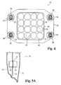
Fig. 4 is a plan view illustrating the shock absorbing member according to the present embodiment, which is viewed from the first shock absorbing portion. -
Fig. 5A is a cross-sectional view of a side door in which the shock absorbing member according to the present embodiment is mounted, in a state before the shock absorbing member experiences a shock. -
Fig. 5B is a cross-sectional view of the side door in which the shock absorbing member according to the present embodiment is mounted, in a state after the shock absorbing member experiences a shock. -
Fig. 6 is a side view of the side door in which the shock absorbing member according to the present embodiment is mounted. -
Fig. 7 is a cross-sectional view illustrating a first modification example of the shock absorbing member according to the present embodiment. -
Fig. 8 is a cross-sectional view illustrating a second modification example of the shock absorbing member according to the present embodiment. -
Fig. 9 is a cross-sectional view illustrating a third modification example of the shock absorbing member according to the present embodiment. - Hereinafter, a shock absorbing member according to the present embodiment will be described, with reference to the drawings.
As illustrated inFig. 5A andFig. 6 , a side door (vehicle body) 10 provided in a vehicle-body side portion includes anouter panel 12 provided in a vehicle outer side of theside door 10, and aninner panel 14 provided in a vehicle inner side thereof, wherein adoor panel member 16 is provided between theouter panel 12 and theinner panel 14. Thedoor panel member 16, theouter panel 12 and theinner panel 14 are secured to each other by welding and the like, and ashock absorbing member 18 is mounted in thedoor panel member 16 at a position aligning with a seat bottom portion, which is not illustrated. - Hereinafter, with reference to
Figs. 1 to 4 , the structure of theshock absorbing member 18 will be described.
As illustrated inFig. 1A and Fig. 1B , theshock absorbing member 18 includes a firstshock absorbing portion 20 having an angular shape, and a secondshock absorbing member 22 having an angular shape and, further, theshock absorbing member 18 is provided with a mountingplate 24 between the firstshock absorbing portion 20 and the secondshock absorbing member 18. The firstshock absorbing portion 20 and the secondshock absorbing member 18 have substantially the same outer shape when viewed in a plane, and the mountingplate 24 has a rectangular shape, such that the mountingplate 24 protrudes from the entire peripheries of the firstshock absorbing portion 20 and the secondshock absorbing member 18. - The mounting
plate 24 is provided withengagement portions 26 at its corner portions. As illustrated inFig. 2 , theengagement portions 26 are provided withhole portions 30 into which tapping screws 28 are screwed. Respective angular-shapedsack portions 32 protruding toward the firstshock absorbing portion 20 are communicated with thesehole portions 30, wherein the tapping screws 28 are screwed into these angular-shapedsack portions 32. - Near the root portion of each angular-shaped sack portion 32 (near the mounting plate 24), there is provided a pair of
engagement pieces 34 which is elastically deformable in a state where they are separated from the angular-shapedsack portion 32. The angular-shapedsack portions 32 and theengagement pieces 34 have widths smaller than the nominal diameter of the tapping screws 28. - On the other hand, the
door panel member 16 is provided with a rectangular-shaped mountinghole 36, and the mountinghole 36 is adapted to allow the firstshock absorbing portion 20 to be inserted therethrough. The mountingplate 24 is formed to have an outer shape larger than that of the mountinghole 36, so that the mountingplate 24 is in a surface-to-surface contact with a portion of thedoor panel member 16 which is around the mountinghole 36, in a state where the firstshock absorbing portion 20 is inserted in the mountinghole 36. - Further, near the corner portions of the mounting
hole 36, there are formed placement holes 38 which are adapted to allow the respective angular-shapedsack portions 32 and therespective engagement pieces 34 to be inserted therein. In a state where the angular-shapedsack portions 32 and theengagement pieces 34 are inserted in the respective placement holes 38, if the respective tapping screws 28 are screwed into the angular-shapedsack portions 32 and theengagement pieces 34, this increases the width of theengagement pieces 34, as the tapping screws 28 are screwed into the angular-shapedsack portions 32. This causes theengagement pieces 34 to engage with portions of thedoor panel member 16 which are around the placement holes 38, which causes thedoor panel member 16 to be held and sandwiched between the mountingplate 24 and theengagement pieces 34, thereby preventing theshock absorbing member 18 from being disengaged therefrom. Namely, theshock absorbing member 18 is secured to thedoor panel member 16. - On the other hand, as illustrated in
Fig. 1A, Fig. 1B andFig. 3 , the firstshock absorbing portion 20 and the secondshock absorbing portion 18 have substantially the same outer shape when viewed in a plane, as described above, but the height (H2) of the secondshock absorbing portion 18 is made larger than the height (H1) of the firstshock absorbing portion 20. - The first
shock absorbing portion 20 and the secondshock absorbing portion 18 include rectangular-shapedencirclement walls Fig. 1B , there is arranged a plurality ofribs 44 in a lattice shape, inside theencirclement wall 40. Theribs 44 are formed to have the same height as that of theencirclement wall 40, and theribs 44 are aligned at their tip end surfaces with the tip end surface of theencirclement wall 40. - Further, as illustrated in
Fig. 1A , there is arranged a plurality ofribs 46 in a lattice shape, inside theencirclement wall 42. Theribs 46 are formed to have the same height as that of theencirclement wall 42, and theribs 46 are aligned at their tip end surfaces with the tip end surface of theencirclement wall 42. - The number of the
ribs 46 provided therein is the same as the number of theribs 44, and the wall thickness of theribs 46 is substantially the same as the wall thickness of theribs 44. However, there is a need for taking account of draft tapers for shaping thereof and, therefore, in some cases, the wall thickness of theribs 46 may be slightly different from the wall thickness of theribs 44, depending on the lengths of the ribs. - Further, at the respective intersections of the
ribs 46, there are providedcolumn portions 48. In shaping theshock absorbing member 18, when thisshock absorbing member 18 is separated from a die (not illustrated) used for shaping theshock absorbing member 18, thesecolumn portions 48 receive ejector pins protruding from the die. Therefore, thesecolumn portions 48 are formed to have a larger wall thickness than those of the other portions of theribs 46. Since thesecolumn portions 48 are provided at the respective intersections of theribs 46, theribs 46 themselves can be reinforced. Therefore,column portions 50 are also provided in theribs 44, similarly to in theribs 46. - Further, while there has been described the
shock absorbing member 18 having the firstshock absorbing portion 20, the secondshock absorbing portion 18 and the mountingplate 24 formed by shaping integrally with one another, it is necessary only that the firstshock absorbing portion 20, the secondshock absorbing portion 18, and the mountingplate 24 are formed integrally with one another, and therefore, they can also be integrated with one another by welding and the like, after being shaped. - Hereinafter, effects and benefits of the
shock absorbing member 18 will be described.
As illustrated inFig. 3 , in the present embodiment, the height (H2) of theencirclement wall 42 and theribs 46 in the secondshock absorbing portion 18 in theshock absorbing member 18 is made larger than the height (H1) of theencirclement wall 40 and theribs 44 in the firstshock absorbing portion 20 therein. Since theribs 44 and theribs 46 have substantially the same wall thickness, and the number of theribs 44 and the number of theribs 46 are equal to each other, the secondshock absorbing portion 18 is more brittle than the firstshock absorbing portion 20, since the secondshock absorbing portion 18 is formed to have a larger height than that of the firstshock absorbing portion 20. - In other words, the second
shock absorbing portion 18 has a higher shock absorbing ability than that of the first shock absorbing portion. Namely, in this case, the firstshock absorbing portion 20 and the secondshock absorbing portion 22 are made to have different shock absorbing abilities. - Further, as illustrated in
Fig. 5A , the firstshock absorbing portion 20 is placed in the vehicle inner side, while the secondshock absorbing portion 18 is placed in the vehicle outer side, in order to provide, in the vehicle outer side, a higher shock absorbing ability than that in the vehicle inner side. This can alleviate impulsive forces exerted on the vehicle inner side. - By making the
ribs shock absorbing portion 18 have different lengths, as described above, it is possible to easily control their shock absorbing abilities. Further, since it is necessary only to make theribs shock absorbing portion 18 have different lengths, it is possible to realize a light-weighted and inexpensive structure, in comparison with cases of providing an additional shock absorbing member in the secondshock absorbing portion 18. - In this case, as illustrated in
Fig. 1A and Fig. 1B , the firstshock absorbing portion 20 includes theplural ribs 44 erected therein, and further, includes theencirclement wall 40 encircling theseplural ribs 44. Theencirclement wall 40 is aligned at its tip end surface with the tip end surfaces of theribs 44. Further, similarly to the firstshock absorbing portion 20, the secondshock absorbing portion 18 includes theplural ribs 46 erected therein and, further, includes theencirclement wall 42 encircling theseplural ribs 46. Theencirclement wall 42 is aligned at its tip end surface with the tip end surfaces of theribs 46. - Further, the
plural ribs 44 and theplural ribs 46 are arranged in respective lattice shapes, and theplural ribs 44 and theencirclement wall 40 are coupled to each other, or theplural ribs 46 and theencirclement wall 42 are coupled to each other, so that impulsive forces transmitted to the firstshock absorbing portion 20 and the secondshock absorbing portion 18 can be received by all theplural ribs 44 and theencirclement wall 40 or by all theplural ribs 46 and theencirclement wall 42, while being dispersed longitudinally and laterally. - For example, although not illustrated, if the first
shock absorbing portion 20 does not have a constant height at its end surface, the firstshock absorbing portion 20 receives, at a portion thereof, impulsive forces transmitted thereto from the outside, and the impulsive forces are transmitted from the portion of the firstshock absorbing portion 20 to thedoor panel member 16 through the mountingplate 24. Namely, the firstshock absorbing portion 20 is caused to have portions which can not absorb impulsive energy, thereby resulting in poor effectiveness. - However, as in the present embodiment, the first
shock absorbing portion 20 and the secondshock absorbing portion 18 are made to have respective constant heights at their end surfaces, as illustrated inFig. 5B , the firstshock absorbing portion 20 can receive, at its entire surface, impulsive forces from the outside (an arrow), and the impulsive energy can be absorbed by deformations of thedoor panel member 16 and the firstshock absorbing portion 20 through the mountingplate 24, thereby resulting in excellent effectiveness. - Further, if the second
shock absorbing portion 18 impinges on theinner panel 14 due to the deformation of thedoor panel member 16, the secondshock absorbing portion 18 can receive this impulsive force at its entire surface, and the secondshock absorbing portion 18 can absorb the impulsive energy by being deformed thereby. Although not illustrated, a reinforce as a reinforcement bar contacts theshock absorbing member 18. If impulsive energy is absorbed by theshock absorbing member 18, then the remaining impulsive energy is transmitted to this reinforce. - Further, while, in the present embodiment, the
plural ribs 44 and theplural ribs 46 are arranged in respective lattice shapes, it is not necessary that they are arranged in lattice shapes, since it is necessary only to provide predetermined shock absorbing abilities. - For example, although not illustrated, the
plural ribs 44 and theplural ribs 46 can be placed such that they form hexagonal shapes. Further, it is not necessary to couple all the ribs to each other, and each two or more ribs can be coupled to each other, or each two or more ribs can be provided independently. Further, while, in this case, theencirclement walls ribs - Further, in this case, as illustrated in
Fig. 3 , theribs 46 in the secondshock absorbing portion 18 are formed to have a height (H2) larger than the height (H1) of theribs 44 in the firstshock absorbing portion 20, in order to make theribs 46 have a strength lower than that of theribs 44 to make the secondshock absorbing portion 18 have a higher shock absorbing ability than that of the firstshock absorbing portion 20. However, alternatively, as illustrated inFig. 7 , the wall thickness (t2) of theribs 46 can be made smaller than the wall thickness (t1) of theribs 44, in order to make theribs 46 have a strength lower than that of theribs 44 for making the secondshock absorbing portion 18 have a higher shock absorbing ability than that of the firstshock absorbing portion 20. - Also, as illustrated in
Fig. 8 , the number of theribs 46 can be made smaller than the number of theribs 44, in order to make theribs 46 have a lower strength than that of theribs 44, for making the secondshock absorbing portion 18 have a higher shock absorbing ability than that of the firstshock absorbing portion 20. Also, these structures can be combined. - Further, the
encirclement walls ribs encirclement walls ribs encirclement walls ribs Fig. 9 , theencirclement walls ribs
Claims (7)
- A shock absorbing member adapted to be mounted in a door panel member for absorbing shocks from outside of a vehicle, the shock absorbing member comprising:a mounting plate adapted to be mounted in the door panel member;a first shock absorbing portion provided on one surface of the mounting plate to be positioned in a vehicle inner side of the door panel member; anda second shock absorbing portion provided on another surface of the mounting plate to be positioned in a vehicle outer side of the door panel member, said second shock absorbing portion having a higher shock absorbing ability than the first shock absorbing portion;wherein the first shock absorbing portion includes a plurality of first ribs with a same height erected from the mounting plate, and a first encirclement wall erected from the mounting plate and encircling the plurality of first ribs, said first encirclement wall having the height same as that of the plurality of first ribs, andthe second shock absorbing portion includes a plurality of second ribs with a same height erected from the mounting plate, and a second encirclement wall erected from the mounting plate and encircling the plurality of second ribs, said second encirclement wall having the height same as that of the plurality of second ribs.
- A shock absorbing member according to claim 1, wherein the plurality of first ribs and the plurality of second ribs are arranged in lattice shapes, respectively.
- A shock absorbing member according to claim 1, wherein the second ribs are formed longer than the first ribs.
- A shock absorbing member according to claim 1, wherein the second ribs are formed to have a smaller wall thickness than the first ribs.
- A shock absorbing member according to claim 1, wherein a number of the second ribs is less than a number of the first ribs.
- A shock absorbing member according to claim 1, wherein tip end portions to root portions of at least the first ribs or the second ribs have a wall thickness varying stepwise or continuously.
- A shock absorbing structure for absorbing shocks from outside of a vehicle, comprising:the shock absorbing member according to claim 1;wherein the first shock absorbing portion is inserted in a mounting hole formed in the door panel member from the vehicle outer side and placed in the vehicle inner side with respect to the door panel member, the second shock absorbing portion is placed in the vehicle outer side with respect to the door panel member, and the mounting plate is mounted to a portion of the door panel member around the mounting hole.
Applications Claiming Priority (2)
| Application Number | Priority Date | Filing Date | Title |
|---|---|---|---|
| JP2009166824A JP2011021673A (en) | 2009-07-15 | 2009-07-15 | Shock absorbing member and shock absorbing structure |
| PCT/JP2010/062009 WO2011007844A1 (en) | 2009-07-15 | 2010-07-15 | Shock absorbing member and shock absorbing structure |
Publications (2)
| Publication Number | Publication Date |
|---|---|
| EP2455636A1 true EP2455636A1 (en) | 2012-05-23 |
| EP2455636A4 EP2455636A4 (en) | 2012-12-12 |
Family
ID=43449454
Family Applications (1)
| Application Number | Title | Priority Date | Filing Date |
|---|---|---|---|
| EP10799902A Withdrawn EP2455636A4 (en) | 2009-07-15 | 2010-07-15 | Shock absorbing member and shock absorbing structure |
Country Status (6)
| Country | Link |
|---|---|
| US (1) | US8807303B2 (en) |
| EP (1) | EP2455636A4 (en) |
| JP (1) | JP2011021673A (en) |
| KR (1) | KR20110007034A (en) |
| CN (1) | CN102472348A (en) |
| WO (1) | WO2011007844A1 (en) |
Cited By (1)
| Publication number | Priority date | Publication date | Assignee | Title |
|---|---|---|---|---|
| WO2015136476A1 (en) * | 2014-03-12 | 2015-09-17 | Tres Srl | Polymeric shock absorbing element for a vehicle and longitudinal side member |
Families Citing this family (20)
| Publication number | Priority date | Publication date | Assignee | Title |
|---|---|---|---|---|
| IT1401982B1 (en) * | 2010-09-28 | 2013-08-28 | Tres Srl | POLYMERIC IMPACT ABSORPTION ELEMENT FOR A VEHICLE AND BUMPER STRUCTURE. |
| JP5465197B2 (en) | 2011-02-03 | 2014-04-09 | ジヤトコ株式会社 | Control device for hybrid vehicle |
| WO2013187490A1 (en) * | 2012-06-14 | 2013-12-19 | 株式会社ニフコ | Load-transmitting member and structure for attaching load-transmitting member to vehicle door |
| JP5802190B2 (en) * | 2012-12-20 | 2015-10-28 | 河西工業株式会社 | Car cabin side wall structure |
| US8733819B1 (en) | 2013-01-22 | 2014-05-27 | Ford Global Technologies, Llc | Variable stiffness energy-absorbing component for vehicle occupant protection |
| JP6156291B2 (en) * | 2014-09-01 | 2017-07-05 | トヨタ自動車株式会社 | Vehicle door structure |
| US9868361B2 (en) * | 2014-12-11 | 2018-01-16 | Ford Global Technologies, Llc | Battery impact absorbing system |
| JP6278915B2 (en) * | 2015-02-20 | 2018-02-14 | 株式会社ニフコ | Load transmission member |
| JP6501118B2 (en) | 2015-08-21 | 2019-04-17 | トヨタ紡織株式会社 | Shock absorption structure |
| JP6585561B2 (en) * | 2016-08-08 | 2019-10-02 | トヨタ自動車東日本株式会社 | Shock absorption structure of automobile |
| JP2018066435A (en) * | 2016-10-19 | 2018-04-26 | 日産自動車株式会社 | Impact absorption member and front roof cross member using impact absorption member |
| US10093158B2 (en) * | 2016-10-24 | 2018-10-09 | Ford Global Technologies Llc | Supplemental load transfer trim system |
| JP6649911B2 (en) * | 2017-03-10 | 2020-02-19 | トヨタ紡織株式会社 | Shock absorbing member |
| CN108146204A (en) * | 2017-12-18 | 2018-06-12 | 吉利汽车研究院(宁波)有限公司 | A kind of buffer structure in arrangements for automotive doors |
| US20190264769A1 (en) * | 2018-02-27 | 2019-08-29 | GM Global Technology Operations LLC | Composite energy-absorbing assembly having discrete energy-absorbing elements supported by a carrier plate |
| US10723271B2 (en) * | 2018-11-09 | 2020-07-28 | GM Global Technology Operations LLC | Running board configured for absorbing energy and method of forming same |
| US11466481B2 (en) * | 2019-02-01 | 2022-10-11 | Nissan North America, Inc. | Vehicle door assembly |
| WO2021174146A1 (en) * | 2020-02-27 | 2021-09-02 | Tesseract Structural Innovations, Inc. | Multilayer uniform deceleration unit |
| CN112026703B (en) * | 2020-07-31 | 2021-10-29 | 东风延锋汽车饰件系统有限公司 | an energy absorber |
| JP2024125878A (en) * | 2023-03-06 | 2024-09-19 | トヨタ自動車株式会社 | Energy absorber |
Family Cites Families (14)
| Publication number | Priority date | Publication date | Assignee | Title |
|---|---|---|---|---|
| JP2841165B2 (en) * | 1994-08-30 | 1998-12-24 | 株式会社イノアックコーポレーション | Interior parts for vehicles |
| JPH08295194A (en) * | 1995-04-28 | 1996-11-12 | Kojima Press Co Ltd | Impact absorbing structural body for vehicle |
| JP3575096B2 (en) * | 1995-01-09 | 2004-10-06 | 豊田合成株式会社 | Door trim shock absorbing structure and method of manufacturing the same |
| JP2870447B2 (en) * | 1995-04-03 | 1999-03-17 | 株式会社イノアックコーポレーション | Interior parts for vehicles |
| JPH0911829A (en) * | 1995-07-03 | 1997-01-14 | Inoac Corp | Interior material for vehicle |
| JPH0948301A (en) * | 1995-08-10 | 1997-02-18 | Inoac Corp | Interior trim material for vehicle |
| JP3403276B2 (en) * | 1995-09-08 | 2003-05-06 | 本田技研工業株式会社 | Door shock absorbing structure |
| US6682128B2 (en) * | 1998-02-04 | 2004-01-27 | Oakwood Energy Management, Inc. | Composite energy absorber |
| JP3873565B2 (en) | 2000-02-29 | 2007-01-24 | マツダ株式会社 | Automotive door |
| JP3882448B2 (en) * | 2000-02-29 | 2007-02-14 | マツダ株式会社 | Automobile door and method of assembling the autodoor |
| CN100351121C (en) * | 2003-05-14 | 2007-11-28 | 京洛株式会社 | Shock absorber of car |
| FR2883348B1 (en) * | 2005-03-21 | 2007-04-27 | Faurecia Interieur Ind Snc | INJECTED PIECE, SPACER ENERGY ABSORPTION ASSEMBLY AND METHOD OF MANUFACTURING SUCH ASSEMBLY |
| JP2009051251A (en) | 2007-08-23 | 2009-03-12 | Toyota Motor Corp | Vehicle front structure |
| US8336933B2 (en) * | 2010-11-04 | 2012-12-25 | Sabic Innovative Plastics Ip B.V. | Energy absorbing device and methods of making and using the same |
-
2009
- 2009-07-15 JP JP2009166824A patent/JP2011021673A/en active Pending
-
2010
- 2010-07-02 KR KR1020100063822A patent/KR20110007034A/en not_active Ceased
- 2010-07-15 CN CN2010800315995A patent/CN102472348A/en active Pending
- 2010-07-15 EP EP10799902A patent/EP2455636A4/en not_active Withdrawn
- 2010-07-15 WO PCT/JP2010/062009 patent/WO2011007844A1/en not_active Ceased
- 2010-07-15 US US13/384,107 patent/US8807303B2/en active Active
Cited By (2)
| Publication number | Priority date | Publication date | Assignee | Title |
|---|---|---|---|---|
| WO2015136476A1 (en) * | 2014-03-12 | 2015-09-17 | Tres Srl | Polymeric shock absorbing element for a vehicle and longitudinal side member |
| US10183638B2 (en) | 2014-03-12 | 2019-01-22 | Tres S.R.L. | Polymeric shock absorbing element for a vehicle and longitudinal side member |
Also Published As
| Publication number | Publication date |
|---|---|
| US8807303B2 (en) | 2014-08-19 |
| EP2455636A4 (en) | 2012-12-12 |
| WO2011007844A1 (en) | 2011-01-20 |
| CN102472348A (en) | 2012-05-23 |
| JP2011021673A (en) | 2011-02-03 |
| KR20110007034A (en) | 2011-01-21 |
| US20120152674A1 (en) | 2012-06-21 |
Similar Documents
| Publication | Publication Date | Title |
|---|---|---|
| US8807303B2 (en) | Shock absorbing member and shock absorbing structure | |
| JP6555235B2 (en) | Lower body structure | |
| US9771106B2 (en) | Vehicle body front structure | |
| EP2082946B1 (en) | Front structure for vehicle | |
| EP2915703A1 (en) | Front structure of vehicle body | |
| EP2263902A2 (en) | Support structure for cooling unit for vehicle | |
| CN104443054A (en) | Vehicle front structure | |
| US9321331B2 (en) | Load-transmitting member and vehicle door attachment structure thereof | |
| EP2979932A1 (en) | Bumper joining structure and crush box | |
| JP5501892B2 (en) | Vehicle tow hook mounting structure | |
| US10363964B2 (en) | Stay drop-off structure in case of impact load input | |
| JP2008007044A (en) | Towing hook mounting structure | |
| CN106240504A (en) | Vehicle bumper and the manufacture method of vehicle bumper | |
| KR101430879B1 (en) | Device for fastening a battery module to a bodyshell of a motor vehicle | |
| CN106660504B (en) | vehicle bumper | |
| JP2018008632A (en) | On-vehicle equipment fixing structure | |
| EP2876022A1 (en) | Steering column device | |
| US20160375939A1 (en) | Vehicle and a cradle assembly for the vehicle | |
| JP2008184125A (en) | Body floor structure | |
| JP5630615B2 (en) | Vehicle body structure | |
| US11505135B2 (en) | Vehicle interior structure | |
| JP2009255854A (en) | Clip mounting base | |
| JP2009137430A (en) | Resin back door reinforcement structure | |
| JP5829886B2 (en) | Bumper structure | |
| JP6292088B2 (en) | Vehicle front structure |
Legal Events
| Date | Code | Title | Description |
|---|---|---|---|
| PUAI | Public reference made under article 153(3) epc to a published international application that has entered the european phase |
Free format text: ORIGINAL CODE: 0009012 |
|
| 17P | Request for examination filed |
Effective date: 20120119 |
|
| AK | Designated contracting states |
Kind code of ref document: A1 Designated state(s): AL AT BE BG CH CY CZ DE DK EE ES FI FR GB GR HR HU IE IS IT LI LT LU LV MC MK MT NL NO PL PT RO SE SI SK SM TR |
|
| DAX | Request for extension of the european patent (deleted) | ||
| A4 | Supplementary search report drawn up and despatched |
Effective date: 20121112 |
|
| RIC1 | Information provided on ipc code assigned before grant |
Ipc: B60J 5/00 20060101ALI20121106BHEP Ipc: B60R 21/04 20060101ALI20121106BHEP Ipc: F16F 7/12 20060101AFI20121106BHEP Ipc: F16F 7/00 20060101ALI20121106BHEP Ipc: B60J 5/04 20060101ALI20121106BHEP |
|
| STAA | Information on the status of an ep patent application or granted ep patent |
Free format text: STATUS: THE APPLICATION IS DEEMED TO BE WITHDRAWN |
|
| 18D | Application deemed to be withdrawn |
Effective date: 20130611 |