EP2455580B1 - Steuervorrichtung für Bohrlochventile - Google Patents
Steuervorrichtung für Bohrlochventile Download PDFInfo
- Publication number
- EP2455580B1 EP2455580B1 EP11188986.1A EP11188986A EP2455580B1 EP 2455580 B1 EP2455580 B1 EP 2455580B1 EP 11188986 A EP11188986 A EP 11188986A EP 2455580 B1 EP2455580 B1 EP 2455580B1
- Authority
- EP
- European Patent Office
- Prior art keywords
- control device
- flow control
- fluid pressure
- control apparatus
- control
- Prior art date
- Legal status (The legal status is an assumption and is not a legal conclusion. Google has not performed a legal analysis and makes no representation as to the accuracy of the status listed.)
- Active
Links
Images


Classifications
-
- E—FIXED CONSTRUCTIONS
- E21—EARTH OR ROCK DRILLING; MINING
- E21B—EARTH OR ROCK DRILLING; OBTAINING OIL, GAS, WATER, SOLUBLE OR MELTABLE MATERIALS OR A SLURRY OF MINERALS FROM WELLS
- E21B34/00—Valve arrangements for boreholes or wells
- E21B34/06—Valve arrangements for boreholes or wells in wells
- E21B34/10—Valve arrangements for boreholes or wells in wells operated by control fluid supplied from outside the borehole
-
- E—FIXED CONSTRUCTIONS
- E21—EARTH OR ROCK DRILLING; MINING
- E21B—EARTH OR ROCK DRILLING; OBTAINING OIL, GAS, WATER, SOLUBLE OR MELTABLE MATERIALS OR A SLURRY OF MINERALS FROM WELLS
- E21B23/00—Apparatus for displacing, setting, locking, releasing or removing tools, packers or the like in boreholes or wells
- E21B23/004—Indexing systems for guiding relative movement between telescoping parts of downhole tools
- E21B23/006—"J-slot" systems, i.e. lug and slot indexing mechanisms
Definitions
- the present invention relates to a control apparatus and a method for controlling downhole flow control devices. More particularly, the present invention relates to a control apparatus capable of opening and closing a downhole flow control device and a method of opening and closing a downhole flow control device.
- pressurised hydraulic fluid extends from a surface pump through the wellhead and connects to a downhole device such as a flow control valve(s).
- a downhole device such as a flow control valve(s).
- a production tubing string is closed off for testing. This allows, among other operations, for production packers to be set and tested.
- flow control valves are deployed as part of a tubing string with hydraulic control lines linked to the surface for remote activation.
- Remote activation of conventional double actuating flow control valves generally utilises two control lines, where one control line is used to open the valve and one control line is used to close the valve.
- Four control lines would be needed if two flow control valves were to be operated.
- one control line acts as the operational control line whereby fluid pressure is applied to the valve to cause the valve to open or close and the second control line for each operation of the valve acts as a return line.
- a double actuating control valve may be capable of being fully open to allow maximum flow through the valve, thereby maximising production or injection rates through the production string. This may also allow for easy access to the well and any equipment below the valve. In a fully closed position the valve is operable to close the flow path through the production string to allow testing of the tubing string to be carried out and to allow setting and testing of production packers etc.
- a control apparatus for a downhole flow control device as recited in Claim 1.
- the control apparatus may be used in downhole well completion applications such as onshore and offshore oil recovery.
- the first and second modules may advantageously facilitate independent remote activation of two flow control devices using only two control lines from surface.
- the first control line may be an operational control line for activating a first flow control device and the second control line may act as a return line for the first flow control device.
- the second control line may be an operational control line for activating a second flow control device and the first control line may act as a return line for the second flow control device.
- the return line provided by the first control line may be adapted to provide feedback indicating activation of the second flow control device.
- the return line provided by the second control line may be adapted to provide feedback indicating activation of the first flow control device.
- the flow control devices may be operated independently of each other and may therefore independently open and close an associated flow control device.
- the operation of each flow control device may therefore be dependent only on which of the two control lines provides fluid pressure to the flow control devices via the associated module.
- the first and second modules may therefore be operated independently.
- the present invention may operate two flow control devices independently of each other using only two control lines. By reducing the complexity of the system to use only two control lines the time and cost of installing and also maintaining control lines may be reduced. In addition, material handling and the cost of materials compared with conventional systems may also be reduced.
- the control apparatus may operate on a closed loop hydraulic circuit, with the lines hydrostatically balancing each other. Therefore, deployment of the downhole valves does not need to be depth dependent as found in prior art systems. Fluid pressure applied via the operational control line may be returned via the other control line. Therefore, feedback may be provided to indicate if the flow control device has functioned correctly.
- each flow control device may be controlled by a flow path through each of the modules, where the flow path may be defined by the switching member.
- the switching member may form part of an actuating piston or alternatively may be a separate component part.
- the switching member may be adapted to rotate, twist and/or turn upon application of fluid pressure via the operational control line such that the flow path may be directed to the relevant output of the module and thereby actuate the flow control device.
- the flow path on the switching member may be defined by one or more directional channels.
- the one or more directional channels defining the flow path may be arranged such that fluid entering the flow path is translated to an outlet only after the switching member rotates, turns, and/or twists to direct the applied fluid to the correct output port for actuation of the flow control device. Rotation, turning and/or twisting of the switching member may divert the flow path of the fluid towards the respective outlet.
- Movement of the piston member may be limited to axial or substantially axial translation only.
- the piston may be prevented from rotation such that only the switching member rotates by a desired amount to ensure correct diversion of the flow path of the fluid towards the respective outlet.
- the piston member may comprise guiding means to minimize any rotation of the piston member during axial translation.
- Axial translation of the piston member may cause rotation of the switching member.
- the piston member may comprise engaging means operable to engage with the switching member to cause rotation of the switching member.
- the engaging means may be a protruding component, such as a lug or key that may be adapted to engage with one or more guiding slots provided in the surface of the switching member.
- the engaging means may be arranged to move axially together with the piston member and to follow a path defined by the one or more slots on the switching member to cause rotation of the switching member.
- the one or more slots may include at least one angular section.
- the one or more slots may also include at least one axial section.
- Axial translation of the piston member and the engaging means may convert to angular movement of the switching member to divert the fluid flow path towards a respective outlet.
- the piston member may be biased in one direction, for example, by a compression spring. Under the application of fluid pressure from the operational control line the piston member may translate axially in one direction only. Axial translation of the piston member in one direction, opposite to the biased to direction, may be caused by application of hydraulic fluid pressure in the same direction as the desired axial translation. Return of the piston member to the biased to direction may occur on removal of the application of hydraulic fluid pressure.
- Each module may comprise a unidirectional flow valve, for example a ball check valve, that may be adapted to be in fluid communication with the fluid flow path in fluid communication with the operational control line.
- the unidirectional valve may be adapted to prevent activation of the flow control device when fluid pressure is applied via the control line designated as a return line for the particular flow control device. Therefore, independent control of each flow control device may be ensured.
- a first indexing module may comprise a first and second inlet port, and a first and second outlet port.
- the first inlet port may be in fluid communication with a first control line and the second inlet port may be in fluid communication with a second control line.
- the outlet ports may be in fluid communication with their respective flow control device such that when fluid pressure is applied via the respective control line and directed to the respective outlet then the respective flow control device may move to the open or closed position as is appropriate.
- the axial translation or substantially axial translation of the piston member may be dependent on the level of fluid pressure applied. Physical activation of the switching member to rotate may also be dependent on the level of fluid pressure applied. Rotation of the switching member may divert the flow path to an associated flow control device.
- the control apparatus may also comprise a limiting mechanism adapted to limit travel of the piston member when the fluid pressure applied is within a first predetermined range of about 69 to 172 bar (about 1000 to 2500 PSI).
- the limiting mechanism may be operable to limit travel of the piston member if the applied fluid pressure is below or within a first predetermined range of about 69 to 172 bar (about 1000 to 2500 PSI). Rotation of the switching member may be prevented if the applied fluid pressure is below or within a first predetermined range of about 69 to 172 bar (about 1000 to 2500 PSI).
- the switching member may be adapted to rotate in one direction upon application of fluid pressure via the operational control line and to rotate in an opposite direction on removal of applied pressure.
- the switching member may be biased in one orientation where the flow path through the device is arranged through a first outlet. Rotation of the switching member may be prevented when the applied pressure is within a first predetermined range of about 69 to 172 bar (about 1000 to 2500 PSI) such that fluid exits through the first outlet. Rotation of the switching member may divert the flow path of the fluid towards a second outlet only when the applied pressure is within a second predetermined range of about 205 to 345 bar (about 3000 to 5000 PSI).
- the second predetermined pressure range may be higher than the first predetermined range.
- the first predetermined pressure range may be about 69 to 172 bar (about 1000 to 2500 PSI).
- the second predetermined pressure range may be about 205 to 345 bar (about 3000 to 5000 PSI).
- the method may therefore be used to open and close a downhole flow control device in a downhole well completion.
- the control apparatus may be as defined in the first aspect.
- a well bore comprising a control apparatus as defined in the first aspect.
- the present invention resides in the provision of a control apparatus capable of independently opening and closing two downhole flow control devices and a method of independently opening and closing two downhole flow control devices using only two control lines from surface.
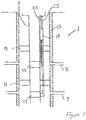
- FIG. 1 there is shown a partial longitudinal sectional view of a completed well bore, generally designated 1.
- the completed well bore 1 includes a substantially tubular production string 3 that extends through particular production zones 5, 7.
- Packers 9, 11 are installed close to and above or substantially above the production zones 5, 7.
- Each packer 9, 11 is operable to isolate an annulus between the tubular string 3 and an inner casing 13 from further downhole in the well bore 1.
- the packers 9, 11 are operable to stop reservoir fluids from flowing up the full length of the inner casing 13.
- the tubular string 3 also includes flow control devices or valves 15, 17.
- the flow control devices or valves 15, 17 may be arranged to be opened or closed to allow or prevent flow through the tubular string 3.
- the flow control devices 15, 17 are each fluidly connected to an indexing carrier 18 comprising two indexing modules 19, 21 which are shown in Figures 2(a) and 2(b) .
- the indexing carrier 18 is generally located above or substantially above the flow control devices 15, 17, with the indexing modules 19, 21 located on the outside of the carrier 18, in the annulus between the tubular string 3 and the casing 13.
- Two control lines 23, 25, located above or substantially above the indexing carrier 18, fluidly connect each of the indexing modules 19, 21 with an associated flow control device 15, 17.
- control lines 23, 25 are each operable to control independent opening and closing of an associated flow control device 15, 17 as described further below.
- FIG. 2(a), 2(b) and 2(c) there is shown a schematic layout of the arrangement of the tubular string 3, the flow control devices 15, 17, the indexing modules 19, 21 and the control lines 23, 25.
- the first indexing module 19 shown in Figure 2(a) comprises a first inlet port 27, a second inlet port 29, a first outlet port 31 and a second outlet port 33.
- the first inlet port 27 is in fluid communication with the first control line 23 and the second inlet port 29 is in fluid communication with the second control line 25.
- the outlet ports 31, 33 are arranged to be in fluid communication with the first flow control device 15 such that when fluid pressure is applied via the first control line 23 and directed to outlet 31 the flow control device 15 moves to the closed position.
- the outlet port 33 is arranged in fluid communication with the first flow control device 15 such that when fluid pressure is applied via the first control line 23 and directed to outlet 33 the flow control device 15 returns to the open position.
- the second indexing module 21 shown in Figure 2(b) operates in the same way as the first, but is arranged to be in fluid communication with the second control device 17. Accordingly, the second indexing module 21 comprises a first inlet port 35, a second inlet port 37, a first outlet port 39 and a second outlet port 41.
- the first inlet port 35 is in fluid communication with the second control line 25 and the second inlet port 37 is in fluid communication with the first control line 23.
- the outlet ports 39, 41 are arranged to be in fluid communication with the second flow control device 17 such that when fluid pressure is applied via the second control line 25 and directed to outlet 39 the flow control device 17 moves to the closed position.
- the outlet port 41 is arranged in fluid communication with the second flow control device 17 such that when fluid pressure is applied via the second control line 25 and directed to outlet 41 the flow control device 17 moves to the open position.
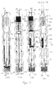
- FIG. 3(a), 3(b), 3(c) and 3(d) An example of the first indexing module 19 and various stages of operation when fluid pressure is applied are illustrated in Figures 3(a), 3(b), 3(c) and 3(d) .
- the first indexing module 19 is illustrated in cross-section and represents the status of the system when no pressure is applied via either of the control lines 23, 25 (shown as phantom lines).
- the first indexing module 19 comprises a tubular casing 43 in which there is provided a movable piston 45 which is biased in the position illustrated by, for example, a compression spring 47.
- a switching or toggle member 49 is shown in cross-section with a central portion illustrated in full in Figures 3(a) and 3(b) to illustrate the surface form of the toggle member 49, which is discussed in more detail below.
- the first indexing module 19 also includes a unidirectional valve 51.
- the unidirectional valve 51 is represented by a ball and spring arrangement (ball check valve) as an example of a suitable unidirectional valve and to illustrate how the flow path through the valve 51 is limited to flow in one direction only.
- the unidirectional valve 51 is operable to allow flow in the direction of the outlets 31, 33 only. It will be appreciated that any suitable non-return or unidirectional valve may be used.
- the toggle member 49 is operable to rotate, turn and/or twist about the axis of the piston 45 on application of fluid pressure from the operational control line 23, 25.
- the term operational control line relates to the control line that delivers fluid pressure to cause a flow control device 15, 17 to open or close. Therefore, the first control line 23 is the operational control line for the first indexing module 19 and the first flow control device 15 and the second control line 25 is the operational control line for the second indexing module 21 and the second flow control device 17.
- the toggle member 49 comprises a helical slot arrangement 56, known generally as a J-slot, formed in the surface of the toggle member 49.
- a key 54 is located in a keyway 60 on the piston 45. The operation of the key 54 relative to the slot 56 is explained further below with reference to Figure 3(b) .
- the piston 45 is guided to move only in an axial direction.
- the tubular casing 43 includes a key 62 that is arranged to engage with a keyway 58 provided on the piston 45. The arrangement of the key 62 and the keyway 58 prevents the piston 45 from rotating (due to reactive torque from the toggle member 49).
- FIG. 3(b) the operation of the first indexing module 19 is illustrated as fluid pressure is applied through the first inlet port 27 via the first control line 23 (indicated by solid arrow 57).
- the darker shaded areas in Figures 3(b) and 3(c) represent fluid in the system as applied via the first control line 23.
- Rotation of the toggle member 49 diverts the flow path of the fluid towards the second outlet 31 as shown by flow path 57 and as illustrated in Figure 3(c) .
- the flow path 57 as illustrated in Figure 3(c) is indicative of fluid exiting the first indexing module 19 via the outlet 31 and then passing to the first flow control device 15 or close the flow control device 15.
- Return flow, from the first flow control device 15, is represented by the arrows showing flow path 59.
- Return flow 59 from the first flow control device 15 passes up through the outlet port 33 of the first indexing module 19 and is returned upstream via the second inlet port 29 and hence the second control line 25.
- the return flow 59 can be used to provide feedback to indicate correct operation of the flow control device 15.
- Figure 3(d) shows the effect of applying fluid pressure to the second inlet port 29 of the first indexing module 19 via the second control line 25, as indicated by flow path 61.
- the fluid pressure in this case acts on the return side of the piston 45 and against the non-return valve 51 such that the pressure at both outlets 31, 33 on the outlet side of the indexing module 19 is balanced. Therefore, fluid pressure applied through the second control line 25 to the first indexing module 19 has no effect on the status of the first flow control device 15.
- the first flow control device 15 is operable between fully open and fully closed only when fluid pressure is applied via the first control line 23 through the first indexing module 19.
- the indexing modules 19, 21 allow for independent control of each flow control device 15, 17.
- the fluid pressure is applied via the operational control line 23, 25 associated with the flow control device 15, 17 to change the status of the flow control device from fully open to fully closed or from fully closed to fully open.
- the flow control devices 15, 17 will maintain the fully open or fully closed position even when fluid pressure is removed or bled off.
- the indexing modules 19, 21 each comprise a mechanical return spring 47, which on bleeding off pressure, will act on the piston 45 to return it axially to the position illustrated in Figure 3(a) .
- the status of the flow control device 15, 17 will remain unaffected until fluid pressure is again applied via the operational control line to cause rotation of the toggle member 49.
- FIGS 3 (a) to (d) equally apply to the operation of the second indexing module 21.
- the operation and function of the second indexing module 21 is the same as the first indexing module 19, except that fluid pressure is applied via the second control line 25 and return flow is via the first control line 23 and that the second flow control device 17 is controlled by the second indexing module 21.
- FIG. 4 A further embodiment of the invention is illustrated in Figures 4 , 5(a) to 5(d) and Figure 6 .
- control apparatus 100 that operates to independently control the opening and closing of two downhole flow control devices 150, 170 using only two control lines 230, 250.
- the control apparatus 100 comprises two indexing modules 190, 210 that are generally located above the flow control devices 150, 170 in the annulus between the tubular string and the casing of a production well bore.
- Two control lines 230, 250 located above or substantially above the indexing modules fluidly connect each of the indexing modules 190, 210 with an associated flow control device 150, 170.
- a first control line 230 is operable to apply fluid pressure, via the first indexing module 190, to open and close the first control device 150 and a second control line 250 is operable to apply fluid pressure, via the second indexing module 210, to open and close the second flow control device 170.
- fluid pressure is being applied to the system via the first control line 230.
- the flow path through the device is indicated by the darker shaded region and arrows 570 to show the direction of flow at entry to the indexing module 190, through the indexing module 190, at the exit 550 from the indexing module and at the inlet to the first flow control device 150.
- fluid pressure is applied within a predetermined range in order to open the flow control device 150.
- the pressure range appropriate for opening the flow control device is in the region of about 205 to 345 bar (about 3000 to 5000psi). Operation of the indexing modules 190, 210 will be described in more detail below with reference to Figures 5(a) to 5(e) and Figure 6 .
- the second control line 250 acts as a return line as indicated by the arrows 580. Fluid pressure acting on the second indexing module 210 from the first control line 230 is hydrostatically balanced and hence the status of the second flow control device 170 is not affected by fluid pressure applied through the first control line 230.
- the return line provided by the second control line 250 may be adapted to provide feedback indicating activation of the first flow control device 150.
- the return line is provided by the first control line 230, which may also be adapted to provide feedback indicating activation of the second flow control device 170.
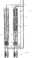
- Figures 5(a) to 5(e) illustrate the first indexing module 190 at various stages of operation.
- Figure 5(a) illustrates the first indexing module 190 and represents its status as it is run into the well bore.
- Figure 5(a) is also representative of the status of the second indexing module 210 when run into the well bore.
- Figure 5(b) illustrates the first indexing module 190 and its status when fluid pressure is applied via the first control line 230 at a level sufficient to close the first flow control device 150.
- Figure 5(b) also shows the flow path 570 through the first indexing module 190 when fluid pressure is applied via the first control line 230 at a level sufficient to close the first flow control device 150.
- Figure 5(b) is also representative of the status of the second indexing module 210 when fluid pressure is applied via the second control line 250 at a level sufficient to close the second flow control device 170.
- Figure 5(c) illustrates the first indexing module 190 and its status when fluid pressure is applied through the first control line 230 at a level sufficient to open the first flow control device 150.
- Figure 5(c) also shows the flow path 570 through the first indexing module 190 when fluid pressure is applied through the first control line 230 at a level sufficient to open the first flow control device 150.
- Figure 5(c) is also representative of the status of the second indexing module 210 when fluid pressure is applied via the second control line 250 at a level sufficient to open the second flow control device 170.
- Figure 5(d) illustrates the first indexing module 190 and its status when no pressure is applied (as in Figure 5(a) ) or when pressure is bled off.
- Figure 5(d) is also representative of the status of the second indexing module 210 when no pressure is applied (as in Figure 5(a) ) or when pressure is bled off.
- Figure 5(e) illustrates the status of the first indexing module 190 when fluid pressure is applied to the control apparatus via the second control line 250.
- Figure 5(e) is also representative of the status of the second indexing module 210 when fluid pressure is applied to the control apparatus via the first control line 230.
- the indexing module 190 comprises a tubular casing 430.
- an actuating piston 450 Within the tubular casing 430 there is housed an actuating piston 450, a latch mechanism 460, a first holding spring 470, a limiter 480 to limit axial translation of the actuating piston 450, a switching or toggle member 490, a second holding spring 500 and a unidirectional flow valve 510.
- the unidirectional valve 510 is represented in Figures 5(a) to 5(e) by a ball and spring arrangement (ball check valve) as an example of a suitable unidirectional valve and to illustrate how the flow path through the valve 510 is limited to flow in one direction only.
- the unidirectional valve 510 operates to allow flow in the direction towards the outlet only. It will be appreciated that any suitable non-return or unidirectional valve may be used.
- the first indexing module 190 comprises a first inlet port 520, a second inlet port 530, a first outlet port 540 and a second outlet port 550.
- the first inlet port 520 is in fluid communication with the first control line 230 and the second inlet port 530 is in fluid communication with the second control line 250.
- Two outlet ports 540, 550 are arranged in fluid communication with the first flow control device 150 such that when fluid pressure is applied via the first control line 230 and directed to a first outlet 540 the flow control device 150 moves to the closed position.
- the second outlet port 550 is arranged in fluid communication with the first flow control device 150 such that when fluid pressure is applied via the first control line 230 and directed to outlet 550 the flow control device 150 returns to the open position.
- the tubular casing 430 includes a central stem portion 431 that includes a thru bore 432, an increased diameter (bulging) portion 433 approximately mid length and a key slot 434 at the lower end of the stem 431.
- the key slot 434 forms part of the limiter 480 to prevent rotation of the actuating piston 450 within the tubular casing 430.
- the limiter 480 also includes a key 435 as part of the actuating piston 450. The key 435 is guided in the key slot 434 to prevent rotation of the actuating piston 450 within the tubular casing 430 and to limit movement of the actuating piston 450 to axial translation only.
- the latch mechanism 460 generally known as a collet latch, together with the first holding spring 470 is arranged to limit the distance travelled by the actuating piston 450 when fluid pressure is applied within a first predetermined range. This is illustrated and discussed further below with reference to Figure 5(b) .
- the latch mechanism 460 includes a sleeve 462 that moves telescopically relative to the stem 431.
- the sleeve 462 includes an upper stop 463 that may be in the form of flexible fingers or keys that act against a stop 464 on the actuating piston 450. The radial position of the stop 463 is held in position by the bulging portion 433 of the stem 431.
- the stops 463, 464 act together to limit axial translation of the actuating piston 450 when the fluid pressure applied via the first control line 230 is below or within the predetermined range.
- fluid pressure is applied in the range of about 69 to 172 bar (about 1000 to 2500 PSI).
- the sleeve 462 includes a lower stop 465 and the stem 431 includes a lower stop 466 between which is arranged the first holding spring 470, which acts to bias the sleeve 462 to the position where the upper stop 463 is in contact with the bulging portion 433 of the stem 431.
- the fluid pressure P2 applied via the first control line 230 is greater than a predetermined value the fluid pressure exceeds the spring force of the first holding spring 470.
- the stop 464 acts against the stop 463 on the latch mechanism to push it below the bulging portion 433 on the stem 431 such that the stop 463 flexes inward and allows the stop 464 to move down (to the right as viewed in Figure 5(c) ) and allows the actuating piston 450 to travel further axially within the tubular casing 430.
- the pressure range appropriate to open the flow control device is in the region of about 205 to 345 bar (about 3000 to 5000psi).
- Figure 5(c) also illustrates the flow direction of fluid as fluid pressure is applied via the first control line 230.
- the action of the actuating piston 450 causes a key 563 to travel axially with the actuating piston 450.
- the key 563 engages with a slot 560 in the toggle member 490 as illustrated in Figure 6 .
- the axial movement of the actuating piston 450 causes rotation of the toggle member 490 such that the flow path is diverted from port 540 to align with and exit from the outlet port 550 such that the first flow control device 150 is opened.
- the toggle member 490 is operable to control the direction of flow from the indexing module 190 to the first indexing module 150.
- the toggle member 490 includes one or more slots 560.
- the slots 560 each include an axial portion 561 and an angular portion 562.
- the slots 560 are independent of each other and are arranged to engage with a key or keys 563 (see Figures 5(a) to 5(e) ) arranged to connect the toggle member 490 and the actuating piston 450.
- the toggle member 490 also includes a seal 564 at one end to prevent fluid ingress between the toggle member 490 and the actuating piston and a shoulder 565 at the opposite end to provide a seat for a return spring 500.
- the movement of the toggle member 490 is a twist and return action.
- the axial movement of the actuating piston 450 causes the key 563 to move axially also, at which time the key 563 engages with the angular part 562 of slot 560 on the toggle member 490 (see Figure 6 ) and causes the toggle member 490 to rotate and therefore shifts the flow path from alignment with first outlet port 540 to align with the second outlet port 550.
- Figure 5(d) shows the effect of removing applied fluid pressure from the system and shows that the mechanical action of the holding springs causes the indexing module 190 to reset itself to the condition it was in when first run into the well bore as illustrated in Figure 5(a) .
- the status of the flow control device 150, 170 will remain unaffected until fluid pressure is again applied via the operational control line 230, 250.
- Figure 5(e) shows the effect of applying fluid pressure to the second inlet port 530 of the first indexing module 190 via the second control line 250, as indicated by flow path 610.
- the fluid pressure acts on the return side of the piston 450 and against the non-return valve 510 such that the pressure at both outlets 540, 550 on the outlet side of the indexing module 190 is balanced. Therefore, fluid pressure applied through the second control line 250 to the first indexing module 190 has no effect on the status of the first flow control device 190.
- the first flow control device 190 is operable between fully open and fully closed only when fluid pressure is applied via the first control line 230 through the first indexing module 190.
- Figures 5(a) to 5(e) also relate to the operation of the second flow control device 170 and the operation of the second indexing module 210.
- the operation and function of the second indexing module 210 is the same as the first indexing module 190, except that fluid pressure is applied via the second control line 250 and return flow is via the first control line 230 and that the second flow control device 170 is controlled by the second indexing module 210.
- the flow control devices 150, 170 are run into the well bore in the open position. Therefore, the first operation of either indexing module 190, 210 is to close the associated flow control device 150, 170.
Landscapes
- Life Sciences & Earth Sciences (AREA)
- Engineering & Computer Science (AREA)
- Geology (AREA)
- Mining & Mineral Resources (AREA)
- Physics & Mathematics (AREA)
- Environmental & Geological Engineering (AREA)
- Fluid Mechanics (AREA)
- General Life Sciences & Earth Sciences (AREA)
- Geochemistry & Mineralogy (AREA)
- Fluid-Pressure Circuits (AREA)
- Multiple-Way Valves (AREA)
Claims (32)
- Steuervorrichtung für Bohrlochströmungssteuereinrichtungen:
wobei die Vorrichtung ein erstes und ein zweites Modul (19, 21) umfasst, wobei jedes Modul bedienbar ist, um sich fluidisch mit einer jeweiligen Bohrlochströmungssteuereinrichtung (15, 17) zu verbinden:wobei jedes Modul zwei Einlassöffnungen (27; 29, 35; 37) und zwei Auslassöffnungen (31, 33, 39, 41) aufweist;wobei eine Einlassöffnung (27, 35) jedes Moduls dazu angepasst ist, fluidisch mit einer ersten Steuerleitung (23), die sich darüber befindet, zu kommunizieren und die andere Einlassöffnung (29, 37) jedes Moduls dazu angepasst ist, fluidisch mit einer zweiten Steuerleitung (25), die sich darüber befindet, zu kommunizieren;wobei das erste Modul bedienbar ist, um eine erste Bohrlochströmungssteuereinrichtung (15) beim Ausüben von Fluiddruck durch die erste Steuerleitung zu öffnen und zu schließen; undwobei das zweite Modul bedienbar ist, um eine zweite Bohrlochströmungssteuereinrichtung (17) beim Ausüben von Fluiddruck durch die zweite Steuerleitung zu öffnen und zu schließen,wobei jedes Modul ein Schaltelement (49) umfasst, das einen Fluidströmungsweg definiert und wobei das Schaltelement während des Ausübens von Fluiddruck von einem von der ersten oder der zweiten Steuerleitung bedienbar ist, um einen Fluiddruck an eine der beiden Auslassöffnungen zu leiten, um ein Öffnen von einem von der ersten und der zweiten Bohrlochströmungssteuereinrichtung zu aktivieren,und wobei das Schaltelement während des Ausübens von Fluiddruck von der einen von der ersten und der zweiten Steuerleitung bedienbar ist, um einen Fluiddruck an die andere der beiden Auslassöffnungen zu leiten, um ein Schließen der einen von der ersten oder der zweiten Bohrlochströmungssteuereinrichtung zu aktivieren. - Steuervorrichtung nach Anspruch 1, wobei das erste und das zweite Modul dazu fähig sind, unabhängig und aus der Ferne die erste und die zweite Bohrlochströmungssteuereinrichtung zu aktivieren.
- Steuervorrichtung nach Anspruch 2, wobei Fernaktivierungsmittel verwendet werden, um die beiden Bohrlochströmungssteuereinrichtungen aus der Ferne zu aktivieren.
- Steuervorrichtung nach einem der vorhergehenden Ansprüche, wobei die erste Steuerleitung während der Verwendung eine operative Steuerleitung bereitstellt, die bedienbar ist, um die erste Bohrlochströmungssteuereinrichtung aus der Ferne zu aktivieren und die zweite Steuerleitung eine operative Steuerleitung bereitstellt, die bedienbar ist, um die zweite Bohrlochströmungssteuereinrichtung aus der Ferne zu aktivieren, und wobei die erste und die zweite Steuerleitung jeweils eine erste und eine zweite Rückführleitung für die zweite Bohrlochströmungssteuereinrichtung und die erste Bohrlochströmungssteuereinrichtung bereitstellen.
- Steuervorrichtung nach Anspruch 4, wobei die erste Rückführleitung, die durch die erste Steuerleitung bereitgestellt wird, dazu angepasst ist, eine Rückkopplung bereitzustellen, die eine Aktivierung der zweiten Bohrlochströmungssteuereinrichtung anzeigt.
- Steuervorrichtung nach Anspruch 4 oder 5, wobei die zweite Rückführleitung, die von der zweiten Steuerleitung bereitgestellt wird, dazu angepasst ist, eine Rückkopplung bereitzustellen, die eine Aktivierung der ersten Bohrlochströmungssteuereinrichtung anzeigt.
- Steuervorrichtung nach Anspruch 4, 5 oder 6, wobei jedes Modul ein Kolbenelement (45) umfasst, das dazu angepasst ist, während des Ausübens von Fluiddruck von der operativen Steuerleitung axial in eine Richtung zu übersetzen, und wobei das Kolbenelement vorgespannt ist, um bei einem Entfernen der Ausübung von Fluiddruck axial in eine entgegengesetzte Richtung zu übersetzen.
- Steuervorrichtung nach Anspruch 7, wobei das Kolbenelement dazu angepasst ist, linear entlang seiner Achse zu übersetzen.
- Steuervorrichtung nach einem der Ansprüche 4 bis 8, wobei das Schaltelement dazu angepasst ist, sich während der Ausübung von Fluiddruck auf den Fluidströmungsweg von der operativen Steuerleitung zu drehen, umzuwenden oder sich zu verbiegen.
- Steuervorrichtung nach Anspruch 9, wobei das Schaltelement bedienbar ist, um sich vollständig zu drehen.
- Steuervorrichtung nach Anspruch 9 oder 10, wobei das Schaltelement bedienbar ist, um sich in einem oder mehreren Inkrementen einer vollen Umdrehung zu drehen.
- Steuervorrichtung nach Anspruch 11, wobei jedes Inkrement eine halbe Umdrehung ist.
- Steuervorrichtung nach Anspruch 11 oder 12, wobei jedes Inkrement einen Strömungsweg durch das Schaltelement an eine der beiden Auslassöffnungen umlenkt.
- Steuervorrichtung nach Anspruch 9, wobei das Schaltelement bedienbar ist, um sich in eine Richtung zu drehen und in die entgegengesetzte Richtung um seine Achse zurückzukehren.
- Steuervorrichtung nach Anspruch 14, wobei jede Drehung ein Inkrement einer vollen Umdrehung ist.
- Steuervorrichtung nach Anspruch 14 oder 15, wobei eine Drehung in eine Richtung einen Strömungsweg durch das Schaltelement zu einer Auslassöffnung umlenkt und eine Drehung in die entgegengesetzte Richtung den Strömungsweg zu der anderen Auslassöffnung umlenkt.
- Steuervorrichtung nach Anspruch 14, 15 oder 16, wobei ein ausgeübter Fluiddruck innerhalb eines vorbestimmten Bereichs bedienbar ist, um eine Drehung des Schaltelements zu aktivieren.
- Steuervorrichtung nach Anspruch 17, wobei ein ausgeübter Druck in dem Bereich von 205 bis 345 bar (3000 bis 5000 psi) eine Drehung des Schaltelements aktiviert.
- Steuervorrichtung nach einem der vorhergehenden Ansprüche, wobei das Schaltelement einen oder mehrere Führungsschlitze (56) umfasst.
- Steuervorrichtung nach Anspruch 19, wobei ein Eingriffselement (54), das als Teil eines Kolbenelements angepasst ist, dazu angepasst ist, mit dem einen oder den mehreren Führungsschlitzen in Eingriff zu stehen.
- Steuervorrichtung nach Anspruch 20, wobei der eine oder die mehreren Führungsschlitze mindestens einen Winkelbereich umfassen.
- Steuervorrichtung nach Anspruch 20 oder 21, wobei der eine oder die mehreren Führungsschlitze mindestens einen axialen Bereich und einen Winkelbereich umfassen.
- Steuervorrichtung nach Anspruch 21 oder 22, wobei das Schaltelement bedienbar ist, um sich zu drehen, wenn das Eingriffselement während der Verwendung einem Weg folgt, der durch einen Winkelbereich der Schlitze definiert ist.
- Steuervorrichtung nach einem der vorhergehenden Ansprüche, ferner umfassend ein unidirektionales Ventil (51), das in Fluidkommunikation mit dem Fluidströmungsweg steht.
- Steuervorrichtung nach einem der vorhergehenden Ansprüche, die einen Hydraulikkreislauf mit geschlossener Schleife umfasst.
- Steuervorrichtung nach einem der vorhergehenden Ansprüche, wobei die Aktivierung zum Öffnen und Schließen der ersten Bohrlochströmungssteuereinrichtung unabhängig von der Aktivierung zum Öffnen und Schließen der zweiten Bohrlochströmungssteuereinrichtung ist.
- Steuervorrichtung nach einem der vorhergehenden Ansprüche, wobei das erste und das zweite Modul für eine Verbindung mit der ersten und der zweiten Steuerleitung über der ersten und der zweiten Steuereinrichtung angepasst sind.
- Steuervorrichtung nach einem der vorhergehenden Ansprüche, wobei eine Aktivierung jeder Strömungssteuereinrichtung dazu fähig ist, durch einen Strömungsweg durch jedes der Module gesteuert zu werden, wobei der Strömungsweg dazu fähig ist, durch das Schaltelement definiert zu werden.
- Steuervorrichtung nach einem der Ansprüche 4 bis 28, wobei jedes Modul ein unidirektionales Strömungsventil umfasst, das dazu fähig ist, dazu angepasst zu sein, in Fluidkommunikation mit einem Fluidströmungsweg zu stehen, der in Fluidkommunikation mit der operativen Steuerleitung steht.
- Verfahren zum Öffnen und Schließen einer Bohrlochströmungssteuereinrichtung unter Verwendung einer Steuervorrichtung, wobei das Verfahren Folgendes umfasst:
Bereitstellen einer Vorrichtung, die ein erstes und ein zweites Modul (19, 21) umfasst, wobei jedes Modul bedienbar ist, um sich fluidisch mit einer jeweiligen Bohrlochsteuereinrichtung (15, 17) zu verbinden:wobei jedes Modul zwei Einlassöffnungen (27, 29, 35, 37) und zwei Auslassöffnungen (31, 33, 39, 41) umfasst;wobei eine Einlassöffnung (27, 35) jedes Moduls dazu angepasst ist, fluidisch mit einer ersten Steuerleitung (23) zu kommunizieren, die sich darüber befindet, und die andere Einlassöffnung (29, 37) jedes Moduls dazu angepasst ist, fluidisch mit einer zweiten Steuerleitung (25) zu kommunizieren, die sich darüber befindet;wobei das erste Modul bedienbar ist, um eine erste Bohrlochströmungssteuereinrichtung (15) beim Ausüben von Fluiddruck durch die erste Steuerleitung zu öffnen und zu schließen; undwobei das zweite Modul bedienbar ist, um eine zweite Bohrlochströmungssteuereinrichtung (17) beim Ausüben von Fluiddruck durch die zweite Steuerleitung zu öffnen und zu schließen;wobei jedes Modul ein Schaltelement (49) umfasst, das einen Fluidströmungsweg definiert, und wobei das Schaltelement während der Ausübung von Fluiddruck von einer von der ersten und der zweiten Steuerleitung bedienbar ist, um einen Fluiddruck an eine der beiden Auslassöffnungen zu leiten, um ein Öffnen von einer von der ersten und der zweiten Bohrlochströmungssteuereinrichtungen zu aktivieren, und wobei das Schaltelement während der Ausübung von Fluiddruck von der einen von der ersten oder der zweiten Steuerleitung bedienbar ist, um einen Fluiddruck an die andere der beiden Auslassöffnungen zu leiten, um ein Schließen der einen von der ersten und der zweiten Bohrlochströmungssteuereinrichtung zu aktivieren. - Verfahren zum Öffnen und Schließen einer Bohrlochströmungssteuereinrichtung nach Anspruch 30, wobei das erste Modul eine erste und eine zweite Einlassöffnung (27, 29) und eine erste und eine zweite Auslassöffnung (31, 33) umfasst, wobei die erste und die zweite Auslassöffnung in Fluidkommunikation mit der ersten Bohrlochströmungssteuereinrichtung stehen, sodass das Schaltelement des ersten Moduls bedienbar ist, um einen Fluiddruck von der ersten Steuerleitung über die erste Einlassöffnung (27) an die erste Auslassöffnung (31) zu leiten, um die erste Bohrlochströmungsvorrichtung in einer ersten geöffneten Position zu aktivieren und an die zweite Auslassöffnung (33) zu leiten, um die erste Bohrlochströmungssteuereinrichtung in einer ersten geschlossenen Position zu aktivieren,
wobei das zweite Modul eine dritte und eine vierte Einlassöffnung (35, 37) und eine dritte und eine vierte Auslassöffnung (39, 41) umfasst, wobei die dritte und die vierte Auslassöffnung in Fluidkommunikation mit der zweiten Bohrlochströmungssteuervorrichtung stehen, sodass das Schaltelement des zweiten Moduls bedienbar ist, um einen Fluiddruck von der zweiten Steuerleitung über die dritte Einlassöffnung (35) an die dritte Auslassöffnung (39) zu leiten, um die zweite Bohrlochströmungssteuereinrichtung in einer zweiten geöffneten Position zu aktivieren und an die vierte Auslassöffnung (41) zu leiten, um die zweite Bohrlochsteuereinrichtung in einer zweiten geschlossenen Position zu aktivieren, und
wobei die erste Einlassöffnung und die vierte Einlassöffnung dazu angepasst sind, fluidisch mit der ersten Steuerleitung zu kommunizieren, und die zweite Einlassöffnung und die dritte Einlassöffnung dazu angepasst sind, fluidisch mit der zweiten Steuerleitung zu kommunizieren. - Bohrloch, das eine Steuervorrichtung nach einem der Ansprüche 1 bis 29 umfasst.
Applications Claiming Priority (1)
| Application Number | Priority Date | Filing Date | Title |
|---|---|---|---|
| GB1019746.5A GB2485608B (en) | 2010-11-22 | 2010-11-22 | Control apparatus for downhole valves |
Publications (3)
| Publication Number | Publication Date |
|---|---|
| EP2455580A2 EP2455580A2 (de) | 2012-05-23 |
| EP2455580A3 EP2455580A3 (de) | 2017-11-29 |
| EP2455580B1 true EP2455580B1 (de) | 2019-01-02 |
Family
ID=43467086
Family Applications (1)
| Application Number | Title | Priority Date | Filing Date |
|---|---|---|---|
| EP11188986.1A Active EP2455580B1 (de) | 2010-11-22 | 2011-11-14 | Steuervorrichtung für Bohrlochventile |
Country Status (3)
| Country | Link |
|---|---|
| US (1) | US8602112B2 (de) |
| EP (1) | EP2455580B1 (de) |
| GB (1) | GB2485608B (de) |
Families Citing this family (11)
| Publication number | Priority date | Publication date | Assignee | Title |
|---|---|---|---|---|
| GB2495502B (en) | 2011-10-11 | 2017-09-27 | Halliburton Mfg & Services Ltd | Valve actuating apparatus |
| GB2497506B (en) | 2011-10-11 | 2017-10-11 | Halliburton Mfg & Services Ltd | Downhole contingency apparatus |
| GB2497913B (en) | 2011-10-11 | 2017-09-20 | Halliburton Mfg & Services Ltd | Valve actuating apparatus |
| GB2495504B (en) | 2011-10-11 | 2018-05-23 | Halliburton Mfg & Services Limited | Downhole valve assembly |
| US9051830B2 (en) * | 2013-08-22 | 2015-06-09 | Halliburton Energy Services, Inc. | Two line operation of two hydraulically controlled downhole devices |
| EP3161259B1 (de) | 2014-06-25 | 2022-03-30 | AOI (Advanced Oilfield Innovations, Inc) | Steuerungssystem für rohrleitungsmontage mit adressierten datagrammen |
| US10280710B2 (en) * | 2015-10-12 | 2019-05-07 | Halliburton Energy Services, Inc. | Auto-shut-in chemical injection valve |
| WO2017070539A1 (en) | 2015-10-23 | 2017-04-27 | Aoi (Advanced Oilfield Innovations, Dba A.O. International Ii, Inc.) | Prime mover system and methods utilizing balanced flow within bi-directional power units |
| US10871174B2 (en) | 2015-10-23 | 2020-12-22 | Aol | Prime mover system and methods utilizing balanced flow within bi-directional power units |
| US10871068B2 (en) | 2017-07-27 | 2020-12-22 | Aol | Piping assembly with probes utilizing addressed datagrams |
| US12454875B2 (en) * | 2019-02-05 | 2025-10-28 | Schlumberger Technology Corporation | System and methodology for selective actuation of a downhole device |
Family Cites Families (7)
| Publication number | Priority date | Publication date | Assignee | Title |
|---|---|---|---|---|
| US5875852A (en) * | 1997-02-04 | 1999-03-02 | Halliburton Energy Services, Inc. | Apparatus and associated methods of producing a subterranean well |
| US6247536B1 (en) * | 1998-07-14 | 2001-06-19 | Camco International Inc. | Downhole multiplexer and related methods |
| US6179052B1 (en) * | 1998-08-13 | 2001-01-30 | Halliburton Energy Services, Inc. | Digital-hydraulic well control system |
| US7182139B2 (en) * | 2002-09-13 | 2007-02-27 | Schlumberger Technology Corporation | System and method for controlling downhole tools |
| US7584800B2 (en) * | 2005-11-09 | 2009-09-08 | Schlumberger Technology Corporation | System and method for indexing a tool in a well |
| GB2434814B (en) * | 2006-02-02 | 2008-09-17 | Schlumberger Holdings | Snorkel Device For Flow Control |
| US7654331B2 (en) * | 2006-02-13 | 2010-02-02 | Baker Hughes Incorporated | Method and apparatus for reduction of control lines to operate a multi-zone completion |
-
2010
- 2010-11-22 GB GB1019746.5A patent/GB2485608B/en active Active
-
2011
- 2011-11-14 EP EP11188986.1A patent/EP2455580B1/de active Active
- 2011-11-15 US US13/296,741 patent/US8602112B2/en active Active
Non-Patent Citations (1)
| Title |
|---|
| None * |
Also Published As
| Publication number | Publication date |
|---|---|
| GB201019746D0 (en) | 2011-01-05 |
| US8602112B2 (en) | 2013-12-10 |
| GB2485608B (en) | 2017-09-13 |
| EP2455580A3 (de) | 2017-11-29 |
| EP2455580A2 (de) | 2012-05-23 |
| US20120125628A1 (en) | 2012-05-24 |
| GB2485608A (en) | 2012-05-23 |
Similar Documents
| Publication | Publication Date | Title |
|---|---|---|
| EP2455580B1 (de) | Steuervorrichtung für Bohrlochventile | |
| EP2221448B1 (de) | Flüssigkeitsdosiervorrichtung und Verfahren für ein Bohrlochwerkzeug | |
| US8215408B2 (en) | Actuation system for well tools | |
| US8256518B2 (en) | Fail as is mechanism and method | |
| US9309745B2 (en) | Interventionless operation of downhole tool | |
| US12247459B2 (en) | System and methodology for actuating a downhole device | |
| US9228402B2 (en) | Anti-stall bypass system for downhole motor | |
| US20090008102A1 (en) | Isolation Valve for Subsurface Safety Valve Line | |
| WO2018140494A1 (en) | Tubular isolation valve resettable lock open mechanism | |
| EP2893122A2 (de) | Mehrtakt-umlaufwerkzeug | |
| WO2010085667A2 (en) | Bidirectional sealing mechanically shifted ball valve for downhole use | |
| US9127528B2 (en) | Multi-position tool actuation system | |
| US20110079394A1 (en) | Multi-stage Pressure Equalization Valve Assembly for Subterranean Valves | |
| US8188881B2 (en) | System and method for controlling multiple well tools | |
| US9695679B2 (en) | Downhole zone flow control system | |
| WO2017118858A1 (en) | Downhole disconnect tool, downhole tool assembly and method | |
| US9316088B2 (en) | Downhole contingency apparatus | |
| US9464505B2 (en) | Flow control system with variable staged adjustable triggering device | |
| EP2971477B1 (de) | Expandierbarer kugelsitz für hydraulisch betätigte werkzeuge | |
| EA042252B1 (ru) | Система подземного оборудования заканчивания скважин |
Legal Events
| Date | Code | Title | Description |
|---|---|---|---|
| PUAI | Public reference made under article 153(3) epc to a published international application that has entered the european phase |
Free format text: ORIGINAL CODE: 0009012 |
|
| AK | Designated contracting states |
Kind code of ref document: A2 Designated state(s): AL AT BE BG CH CY CZ DE DK EE ES FI FR GB GR HR HU IE IS IT LI LT LU LV MC MK MT NL NO PL PT RO RS SE SI SK SM TR |
|
| AX | Request for extension of the european patent |
Extension state: BA ME |
|
| RAP1 | Party data changed (applicant data changed or rights of an application transferred) |
Owner name: HALLIBURTON MANUFACTURING & SERVICES LIMITED |
|
| PUAL | Search report despatched |
Free format text: ORIGINAL CODE: 0009013 |
|
| AK | Designated contracting states |
Kind code of ref document: A3 Designated state(s): AL AT BE BG CH CY CZ DE DK EE ES FI FR GB GR HR HU IE IS IT LI LT LU LV MC MK MT NL NO PL PT RO RS SE SI SK SM TR |
|
| AX | Request for extension of the european patent |
Extension state: BA ME |
|
| RIC1 | Information provided on ipc code assigned before grant |
Ipc: E21B 23/00 20060101ALI20171020BHEP Ipc: E21B 34/10 20060101AFI20171020BHEP |
|
| STAA | Information on the status of an ep patent application or granted ep patent |
Free format text: STATUS: REQUEST FOR EXAMINATION WAS MADE |
|
| 17P | Request for examination filed |
Effective date: 20180322 |
|
| RBV | Designated contracting states (corrected) |
Designated state(s): AL AT BE BG CH CY CZ DE DK EE ES FI FR GB GR HR HU IE IS IT LI LT LU LV MC MK MT NL NO PL PT RO RS SE SI SK SM TR |
|
| RIC1 | Information provided on ipc code assigned before grant |
Ipc: E21B 34/10 20060101AFI20180710BHEP Ipc: E21B 23/00 20060101ALI20180710BHEP |
|
| GRAP | Despatch of communication of intention to grant a patent |
Free format text: ORIGINAL CODE: EPIDOSNIGR1 |
|
| STAA | Information on the status of an ep patent application or granted ep patent |
Free format text: STATUS: GRANT OF PATENT IS INTENDED |
|
| INTG | Intention to grant announced |
Effective date: 20180823 |
|
| GRAS | Grant fee paid |
Free format text: ORIGINAL CODE: EPIDOSNIGR3 |
|
| GRAA | (expected) grant |
Free format text: ORIGINAL CODE: 0009210 |
|
| STAA | Information on the status of an ep patent application or granted ep patent |
Free format text: STATUS: THE PATENT HAS BEEN GRANTED |
|
| AK | Designated contracting states |
Kind code of ref document: B1 Designated state(s): AL AT BE BG CH CY CZ DE DK EE ES FI FR GB GR HR HU IE IS IT LI LT LU LV MC MK MT NL NO PL PT RO RS SE SI SK SM TR |
|
| REG | Reference to a national code |
Ref country code: GB Ref legal event code: FG4D |
|
| REG | Reference to a national code |
Ref country code: CH Ref legal event code: EP Ref country code: AT Ref legal event code: REF Ref document number: 1084612 Country of ref document: AT Kind code of ref document: T Effective date: 20190115 |
|
| REG | Reference to a national code |
Ref country code: IE Ref legal event code: FG4D |
|
| REG | Reference to a national code |
Ref country code: DE Ref legal event code: R096 Ref document number: 602011055309 Country of ref document: DE |
|
| REG | Reference to a national code |
Ref country code: NO Ref legal event code: T2 Effective date: 20190102 |
|
| REG | Reference to a national code |
Ref country code: NL Ref legal event code: MP Effective date: 20190102 |
|
| REG | Reference to a national code |
Ref country code: LT Ref legal event code: MG4D |
|
| REG | Reference to a national code |
Ref country code: AT Ref legal event code: MK05 Ref document number: 1084612 Country of ref document: AT Kind code of ref document: T Effective date: 20190102 |
|
| PG25 | Lapsed in a contracting state [announced via postgrant information from national office to epo] |
Ref country code: NL Free format text: LAPSE BECAUSE OF FAILURE TO SUBMIT A TRANSLATION OF THE DESCRIPTION OR TO PAY THE FEE WITHIN THE PRESCRIBED TIME-LIMIT Effective date: 20190102 |
|
| PG25 | Lapsed in a contracting state [announced via postgrant information from national office to epo] |
Ref country code: FI Free format text: LAPSE BECAUSE OF FAILURE TO SUBMIT A TRANSLATION OF THE DESCRIPTION OR TO PAY THE FEE WITHIN THE PRESCRIBED TIME-LIMIT Effective date: 20190102 Ref country code: LT Free format text: LAPSE BECAUSE OF FAILURE TO SUBMIT A TRANSLATION OF THE DESCRIPTION OR TO PAY THE FEE WITHIN THE PRESCRIBED TIME-LIMIT Effective date: 20190102 Ref country code: PL Free format text: LAPSE BECAUSE OF FAILURE TO SUBMIT A TRANSLATION OF THE DESCRIPTION OR TO PAY THE FEE WITHIN THE PRESCRIBED TIME-LIMIT Effective date: 20190102 Ref country code: ES Free format text: LAPSE BECAUSE OF FAILURE TO SUBMIT A TRANSLATION OF THE DESCRIPTION OR TO PAY THE FEE WITHIN THE PRESCRIBED TIME-LIMIT Effective date: 20190102 Ref country code: SE Free format text: LAPSE BECAUSE OF FAILURE TO SUBMIT A TRANSLATION OF THE DESCRIPTION OR TO PAY THE FEE WITHIN THE PRESCRIBED TIME-LIMIT Effective date: 20190102 Ref country code: PT Free format text: LAPSE BECAUSE OF FAILURE TO SUBMIT A TRANSLATION OF THE DESCRIPTION OR TO PAY THE FEE WITHIN THE PRESCRIBED TIME-LIMIT Effective date: 20190502 |
|
| PG25 | Lapsed in a contracting state [announced via postgrant information from national office to epo] |
Ref country code: RS Free format text: LAPSE BECAUSE OF FAILURE TO SUBMIT A TRANSLATION OF THE DESCRIPTION OR TO PAY THE FEE WITHIN THE PRESCRIBED TIME-LIMIT Effective date: 20190102 Ref country code: HR Free format text: LAPSE BECAUSE OF FAILURE TO SUBMIT A TRANSLATION OF THE DESCRIPTION OR TO PAY THE FEE WITHIN THE PRESCRIBED TIME-LIMIT Effective date: 20190102 Ref country code: LV Free format text: LAPSE BECAUSE OF FAILURE TO SUBMIT A TRANSLATION OF THE DESCRIPTION OR TO PAY THE FEE WITHIN THE PRESCRIBED TIME-LIMIT Effective date: 20190102 Ref country code: IS Free format text: LAPSE BECAUSE OF FAILURE TO SUBMIT A TRANSLATION OF THE DESCRIPTION OR TO PAY THE FEE WITHIN THE PRESCRIBED TIME-LIMIT Effective date: 20190502 Ref country code: GR Free format text: LAPSE BECAUSE OF FAILURE TO SUBMIT A TRANSLATION OF THE DESCRIPTION OR TO PAY THE FEE WITHIN THE PRESCRIBED TIME-LIMIT Effective date: 20190403 Ref country code: BG Free format text: LAPSE BECAUSE OF FAILURE TO SUBMIT A TRANSLATION OF THE DESCRIPTION OR TO PAY THE FEE WITHIN THE PRESCRIBED TIME-LIMIT Effective date: 20190402 |
|
| REG | Reference to a national code |
Ref country code: DE Ref legal event code: R097 Ref document number: 602011055309 Country of ref document: DE |
|
| PG25 | Lapsed in a contracting state [announced via postgrant information from national office to epo] |
Ref country code: AT Free format text: LAPSE BECAUSE OF FAILURE TO SUBMIT A TRANSLATION OF THE DESCRIPTION OR TO PAY THE FEE WITHIN THE PRESCRIBED TIME-LIMIT Effective date: 20190102 Ref country code: AL Free format text: LAPSE BECAUSE OF FAILURE TO SUBMIT A TRANSLATION OF THE DESCRIPTION OR TO PAY THE FEE WITHIN THE PRESCRIBED TIME-LIMIT Effective date: 20190102 Ref country code: CZ Free format text: LAPSE BECAUSE OF FAILURE TO SUBMIT A TRANSLATION OF THE DESCRIPTION OR TO PAY THE FEE WITHIN THE PRESCRIBED TIME-LIMIT Effective date: 20190102 Ref country code: RO Free format text: LAPSE BECAUSE OF FAILURE TO SUBMIT A TRANSLATION OF THE DESCRIPTION OR TO PAY THE FEE WITHIN THE PRESCRIBED TIME-LIMIT Effective date: 20190102 Ref country code: SK Free format text: LAPSE BECAUSE OF FAILURE TO SUBMIT A TRANSLATION OF THE DESCRIPTION OR TO PAY THE FEE WITHIN THE PRESCRIBED TIME-LIMIT Effective date: 20190102 Ref country code: EE Free format text: LAPSE BECAUSE OF FAILURE TO SUBMIT A TRANSLATION OF THE DESCRIPTION OR TO PAY THE FEE WITHIN THE PRESCRIBED TIME-LIMIT Effective date: 20190102 Ref country code: DK Free format text: LAPSE BECAUSE OF FAILURE TO SUBMIT A TRANSLATION OF THE DESCRIPTION OR TO PAY THE FEE WITHIN THE PRESCRIBED TIME-LIMIT Effective date: 20190102 Ref country code: IT Free format text: LAPSE BECAUSE OF FAILURE TO SUBMIT A TRANSLATION OF THE DESCRIPTION OR TO PAY THE FEE WITHIN THE PRESCRIBED TIME-LIMIT Effective date: 20190102 |
|
| PLBE | No opposition filed within time limit |
Free format text: ORIGINAL CODE: 0009261 |
|
| STAA | Information on the status of an ep patent application or granted ep patent |
Free format text: STATUS: NO OPPOSITION FILED WITHIN TIME LIMIT |
|
| PG25 | Lapsed in a contracting state [announced via postgrant information from national office to epo] |
Ref country code: SM Free format text: LAPSE BECAUSE OF FAILURE TO SUBMIT A TRANSLATION OF THE DESCRIPTION OR TO PAY THE FEE WITHIN THE PRESCRIBED TIME-LIMIT Effective date: 20190102 |
|
| 26N | No opposition filed |
Effective date: 20191003 |
|
| PG25 | Lapsed in a contracting state [announced via postgrant information from national office to epo] |
Ref country code: SI Free format text: LAPSE BECAUSE OF FAILURE TO SUBMIT A TRANSLATION OF THE DESCRIPTION OR TO PAY THE FEE WITHIN THE PRESCRIBED TIME-LIMIT Effective date: 20190102 |
|
| PGFP | Annual fee paid to national office [announced via postgrant information from national office to epo] |
Ref country code: FR Payment date: 20191129 Year of fee payment: 9 |
|
| PG25 | Lapsed in a contracting state [announced via postgrant information from national office to epo] |
Ref country code: TR Free format text: LAPSE BECAUSE OF FAILURE TO SUBMIT A TRANSLATION OF THE DESCRIPTION OR TO PAY THE FEE WITHIN THE PRESCRIBED TIME-LIMIT Effective date: 20190102 |
|
| REG | Reference to a national code |
Ref country code: DE Ref legal event code: R119 Ref document number: 602011055309 Country of ref document: DE |
|
| REG | Reference to a national code |
Ref country code: CH Ref legal event code: PL |
|
| PG25 | Lapsed in a contracting state [announced via postgrant information from national office to epo] |
Ref country code: LI Free format text: LAPSE BECAUSE OF NON-PAYMENT OF DUE FEES Effective date: 20191130 Ref country code: MC Free format text: LAPSE BECAUSE OF FAILURE TO SUBMIT A TRANSLATION OF THE DESCRIPTION OR TO PAY THE FEE WITHIN THE PRESCRIBED TIME-LIMIT Effective date: 20190102 Ref country code: CH Free format text: LAPSE BECAUSE OF NON-PAYMENT OF DUE FEES Effective date: 20191130 Ref country code: LU Free format text: LAPSE BECAUSE OF NON-PAYMENT OF DUE FEES Effective date: 20191114 |
|
| REG | Reference to a national code |
Ref country code: BE Ref legal event code: MM Effective date: 20191130 |
|
| PG25 | Lapsed in a contracting state [announced via postgrant information from national office to epo] |
Ref country code: DE Free format text: LAPSE BECAUSE OF NON-PAYMENT OF DUE FEES Effective date: 20200603 Ref country code: IE Free format text: LAPSE BECAUSE OF NON-PAYMENT OF DUE FEES Effective date: 20191114 |
|
| PG25 | Lapsed in a contracting state [announced via postgrant information from national office to epo] |
Ref country code: BE Free format text: LAPSE BECAUSE OF NON-PAYMENT OF DUE FEES Effective date: 20191130 |
|
| PG25 | Lapsed in a contracting state [announced via postgrant information from national office to epo] |
Ref country code: CY Free format text: LAPSE BECAUSE OF FAILURE TO SUBMIT A TRANSLATION OF THE DESCRIPTION OR TO PAY THE FEE WITHIN THE PRESCRIBED TIME-LIMIT Effective date: 20190102 |
|
| PG25 | Lapsed in a contracting state [announced via postgrant information from national office to epo] |
Ref country code: MT Free format text: LAPSE BECAUSE OF FAILURE TO SUBMIT A TRANSLATION OF THE DESCRIPTION OR TO PAY THE FEE WITHIN THE PRESCRIBED TIME-LIMIT Effective date: 20190102 Ref country code: HU Free format text: LAPSE BECAUSE OF FAILURE TO SUBMIT A TRANSLATION OF THE DESCRIPTION OR TO PAY THE FEE WITHIN THE PRESCRIBED TIME-LIMIT; INVALID AB INITIO Effective date: 20111114 |
|
| PG25 | Lapsed in a contracting state [announced via postgrant information from national office to epo] |
Ref country code: FR Free format text: LAPSE BECAUSE OF NON-PAYMENT OF DUE FEES Effective date: 20201130 |
|
| PG25 | Lapsed in a contracting state [announced via postgrant information from national office to epo] |
Ref country code: MK Free format text: LAPSE BECAUSE OF FAILURE TO SUBMIT A TRANSLATION OF THE DESCRIPTION OR TO PAY THE FEE WITHIN THE PRESCRIBED TIME-LIMIT Effective date: 20190102 |
|
| PGFP | Annual fee paid to national office [announced via postgrant information from national office to epo] |
Ref country code: GB Payment date: 20251001 Year of fee payment: 15 |
|
| PGFP | Annual fee paid to national office [announced via postgrant information from national office to epo] |
Ref country code: NO Payment date: 20251024 Year of fee payment: 15 |