EP2455057A1 - Automatic medication dispensing device - Google Patents
Automatic medication dispensing device Download PDFInfo
- Publication number
- EP2455057A1 EP2455057A1 EP10799623A EP10799623A EP2455057A1 EP 2455057 A1 EP2455057 A1 EP 2455057A1 EP 10799623 A EP10799623 A EP 10799623A EP 10799623 A EP10799623 A EP 10799623A EP 2455057 A1 EP2455057 A1 EP 2455057A1
- Authority
- EP
- European Patent Office
- Prior art keywords
- medication
- tray
- section
- flap
- Prior art date
- Legal status (The legal status is an assumption and is not a legal conclusion. Google has not performed a legal analysis and makes no representation as to the accuracy of the status listed.)
- Granted
Links
Images







Classifications
-
- G—PHYSICS
- G07—CHECKING-DEVICES
- G07F—COIN-FREED OR LIKE APPARATUS
- G07F11/00—Coin-freed apparatus for dispensing, or the like, discrete articles
- G07F11/70—Coin-freed apparatus for dispensing, or the like, discrete articles in which the articles are formed in the apparatus from components, blanks, or material constituents
-
- G—PHYSICS
- G07—CHECKING-DEVICES
- G07F—COIN-FREED OR LIKE APPARATUS
- G07F13/00—Coin-freed apparatus for controlling dispensing or fluids, semiliquids or granular material from reservoirs
- G07F13/06—Coin-freed apparatus for controlling dispensing or fluids, semiliquids or granular material from reservoirs with selective dispensing of different fluids or materials or mixtures thereof
-
- G—PHYSICS
- G07—CHECKING-DEVICES
- G07F—COIN-FREED OR LIKE APPARATUS
- G07F17/00—Coin-freed apparatus for hiring articles; Coin-freed facilities or services
- G07F17/0092—Coin-freed apparatus for hiring articles; Coin-freed facilities or services for assembling and dispensing of pharmaceutical articles
Definitions
- the present invention relates to an automatic medication dispensing device which dispenses a medicine based on a prescription instruction in a hospital or the like.
- An automatic medication dispensing device automatically dispenses a medicine in accordance with a prescription to a tray which is prepared for each patient.
- the automatic medication dispensing device is provided with a medication supplying unit which stores medicines in an accommodating section, and which dispenses the medicine based on a prescription instruction.
- the medication supplying unit is provided with supplying means which takes out a desired medicine from the accommodating section, and dispenses the medicine to a tray, and supplying means having various ingenuities have been disclosed in the past (patent document 1 and patent document 2).
- the automatic medication dispensing device inevitably becomes large in size and a large installation space is required because it is necessary to accommodates a large number of medicines and the device requires places where vacant trays as many as the number of patients are prepared and stored and where trays to which medicines are dispensed are accommodated. Further, if various functions are added, a depth dimension of the device is increased and this is a cause of increase in the installation space. Especially in a medium-scale hospital having about 200 to 400 beds, the automatic medication dispensing device exerts effect if the automatic medication dispensing device is introduced, but there is a problem that the device can not be introduced due to the installation space. Hence, an automatic medication dispensing device requiring a small installation space is desired.
- the automatic medication dispensing device also dispenses a medicine which is accommodated in an easily breakable container and which must be handled with the greatest care such as an injection ampule and an instilment bag.
- a medicine container which is accommodated in an easily breakable container and which must be handled with the greatest care
- an injection ampule and an instilment bag such as an injection ampule and an instilment bag.
- one of procedures in which a medicine container is prone to be damaged is a step of taking out a medicine to a step of supplying the medicine to a tray. Therefore, it is desired to realize supplying means which does not easily damage a medicine.
- an object of the present invention to provide an automatic medication dispensing device requiring a small installation space especially a small depth dimension.
- an automatic medication dispensing device having supplying means which supplies accommodated medications to a tray based on the prescription instruction, wherein the supplying means includes a head body section, a pocket section which temporarily holds a taken out medication and which places the medication on the tray, and an arm section which couples the head body section and the pocket section to each other, the pocket section is turnably connected to one end of the arm section through a first shaft, and the other end of the arm section and the head body section are turnably connected to each other through a second shaft.
- the "pocket section" can temporarily hold a taken out medicine and its shape is not limited.
- the "arm section" can connect the head body and the pocket section with each other, its shape is not limited and the arm section need not be of a plate-shape or a rod-shape.
- an abutment section is provided at a position of the head body section closer to the tray than the first shaft, the pocket section is provided with a guide section, the guide section abuts against the abutment section and in this state, the pocket section places a medication on the tray.
- the guide section includes a first guide surface and a second guide surface which is continuous with the first guide surface and which has a curvature or an angle different from that of the first guide surface.
- the device comprises tray conveying means which conveys the tray, the tray conveying means includes moving means which moves the tray toward the pocket section when a medication is placed on the tray.
- the device further comprises tray conveying means which conveys the tray, the tray conveying means includes turning means which rotates the tray in a horizontal direction.
- an automatic medication dispensing device including supplying means which temporarily holds medications accommodated in a medication storing case and then dispenses the medication to a tray based on a prescription instruction, wherein the automatic medication dispensing device includes a flap provided at a position where the flap comes into contact with the medication when the medication is taken out from the medication storing case to the supplying means.
- the "flap" is a cloth body or a plate body whose one end is connected to the supplying means, and it is necessary that the flap can move in a direction in which a medicine moves when the medicine is taken out from the medication storing case to the supplying means.
- the automatic medication dispensing device of claim 7 when the medication in the medication storing case is taken out to the supplying means based on a prescription instruction, the medication is temporarily stopped by the flap, and after the medication is temporarily stopped, the flap is moved, thereby releasing engagement between the medication and the flap to drop the medication into the supplying means.
- the device further comprises holding means which holds the flap at a position where the medication is temporarily stopped and a position where engagement with respect to the medication is released when the medication in the medication storing case is taken out to the supplying means.
- the device further comprises a movable section at a path where the medication is taken out from the medication storing case, an inclination angle of the movable section is changed in an interlocking manner with movement of the flap.
- the automatic medication dispensing device since the automatic medication dispensing device includes the arm section, when a medication is placed on the tray, i.e., when a medication is dispensed, the pocket section can be moved toward a tray located more forward. That is, it is unnecessary to move the tray toward the head body section, or even if the tray is moved, its moving distance can be shortened, depth dimension of the automatic medication dispensing device can be shortened, and it is possible to realize an automatic medication dispensing device requiring a small installation area.
- the automatic medication dispensing device has the arm section, it is possible to supply a medication from a location lower than that of the conventional technique, it is possible to supply a medication to the tray by a method having a smaller impact, and it is possible to prevent a medication from being damaged.
- the guide section and the abutment section are provided. According to this, it is possible to move the pocket section toward a tray located more forward than the abutment section, and to dispense a medication to the tray.
- the tray toward the head body section it is unnecessary to move the tray toward the head body section, or even if the tray is moved, its moving distance can be shortened, depth dimension of the automatic medication dispensing device can be shortened, and it is possible to realize an automatic medication dispensing device requiring a small installation area.
- the abutment section is provided at the position in front of the first shaft, it is possible to reduce the angle of the bottom surface of the pocket section with respect to the tray when a medication is to be dispensed, and even if a medication is accommodated in a breakable medication container, the medication can be moved to the tray slowly, and it is possible to realize supplying means having less possibility of damage of the medication container.
- the guide section is provided a guide surface having a plurality of curvatures or angles, operation of the pocket section can be changed.
- the pocket section is first moved to a location directly above the tray and then, a medication is moved to the tray at a gentle angle between the bottom surface of the pocket section and a bottom surface of the tray, and medications can reliably be transferred to the trays without allowing medications to remain in the pocket section while increasing the angle.
- the tray can be moved toward the head body section, the pocket section and the tray come close to each other and hence, it is possible to dispense a medication more swiftly.
- the moving distance to the tray toward the depth dimension can be shortened by moving the pocket section toward the forward tray.
- the tray can be rotated, even when a medication is to be placed on a region of the tray farthest away from the pocket section, the medication can be placed on the tray by rotating the tray without moving the tray by the moving means. According to this, since the moving distance of the tray in the depth dimension direction can be shortened, the depth dimension of the automatic medication dispensing device can be shortened, and it is possible to realize an automatic medication dispensing device requiring a small installation area.
- the taken out medication comes into contact with the flap and the speed of the medication can sufficiently be reduced, and it is possible to open the flap by the weight of the medication its own, and to reliably drop the medication into the supplying means.
- a medication is temporarily stopped by the flap and the speed of the medication can be brought into zero. After the speed of the medication taken out from the medication storing case is brought into zero, the engagement between the flap and the medication is released and the medication is made to drop into the supplying means.
- the speed of the medication dropping into the supplying means does not correspond to a position of the medication storing case but corresponds to a position where the medication is temporarily stopped. According to this, the height from the supplying means can be lowered and the speed of the medication dropping into the supplying means can be reduced and thus, it is possible to prevent the medication from being damaged. After the medication is temporarily stopped by the flap, the engagement with respect to the flap is released and the medication is made to drop into the supplying means.
- the flap can be held at a predetermined position by the holding means. Hence, it is possible to release the engagement between a medication and the flap and to reliably drop the medication into the supplying means by reliably and temporarily stopping the medication and releasing the flap-holding state by the holding means.
- a medication is temporarily stopped by the flap and the movable section whose inclination angle is changed in the interlocking manner with the movement of the flap, and the speed of the medication taken out into the supplying means can sufficiently be reduced. Therefore, even when a plurality of medications are to be taken out into the supplying means, it is possible to avoid a case where the medications collide against each other and the medications are damaged.
- Fig. 1 is a front view of an outward appearance of an automatic medication dispensing device 101.
- the automatic medication dispensing device 101 includes a non-accommodated tray unit 102, a medication supplying unit 103, a printer unit 104, an accommodated tray unit 105 and tray conveying means 106 which connect these units to one another.
- the non-accommodated tray unit 102 loads and accommodates vacant trays 107 on which various medications are placed, and supplies vacant trays to the tray conveying means 106.
- the vacant tray accommodating unit 102 is provided at its front surface with a door made of clear plastic or glass so that stock of trays can be checked, but this cover is not absolutely required and the trays 107 may be loaded and accommodated such that the trays are exposed.
- the medication supplying unit 103 stores various kinds of medications in a fractionation manner, and supplies and places a medication which is necessary for each patient to and on a vacant tray 107 conveyed from the non-accommodated tray unit 102 by the tray conveying means 106 based on a prescription instruction such as prescription data.
- the medication supplying unit includes a large number of medication cases in which medications are stored by kinds, and supplying means which takes out a desired medication from the medication case based on the prescription instruction by placing the medication on the tray.
- the printer unit 104 includes a printer for printing a prescription on which contents of medicine prescription such as an injection label or printing medication labels of various kinds of medicines are described.
- the printer unit 104 supplies and places the printed prescription and a medication label to and on a tray 107 conveyed from the medication supplying unit 103 by the tray conveying means 106.
- a front surface of the printer unit is covered with an opaque metal or plastic door to prevent dust and foreign matter from entering from outside and the door can be opened and closed.
- Individual information is described on a printed matter printed by the printer, and confidentiality thereof is high. Hence, individual certification means may be provided and the door may be opened and closed.
- Positions of the medication supplying unit 103 and the printer unit 104 may be reversed.
- the accommodated tray unit 105 receives, loads and accommodates a tray 107 conveyed from the printer unit 104 by the tray conveying means 106. At this point, various kinds of medications, injection labels and medication labels are placed on the trays 107.
- the accommodated tray unit 105 is also provided at its front surface with a door made of clear plastic or glass so that accommodated strays can be checked. According to this configuration, it is possible to prevent a tray 107 on which a medicine is placed from being destroyed and to prevent the medicine from being damaged. However, these covers are not absolutely required in terms of function, and the trays 107 may be placed and accommodated such that they are exposed. A tray 107 placed on the accommodated tray unit 105 is transferred to a cart or the like, and conveyed to a doctor or a patient by a nurse or a pharmacist.
- the tray conveying means 106 connect the non-accommodated tray unit 102 to the accommodated tray unit 105 through the medication supplying unit 103 and the printer unit 104 by means such as belt conveyers. According to this embodiment, the tray conveying means 106 are independently provided on lower portion of these units.
- the tray conveying means receives a vacant tray 107 from the non-accommodated tray unit 102, the tray conveying means receives a medication from the medication supplying unit 103, the tray conveying means receives a prescription and a medication label from the printer unit 104 onto the tray 107, and the tray 107 on which the medicine and the prescription are placed is delivered to the accommodated tray unit 105.
- tray conveying means 106 By providing these tray conveying means 106 on a line, trays can be disposed, medications can be supplied, printed matters can be supplied, and trays can be delivered by each unit simultaneously in parallel, and it is possible to realize more swift dispensation. Detailed configuration and movements of the tray transferring means 106 will be described later.
- Fig. 2 is a perspective view of an outward appearance of the tray conveying means of a lower portion of the medication supplying unit.
- Fig. 3 is a configuration diagram of a second conveyor of the tray conveying means which can turn.
- Figs. 2 and 3 show a configuration when trays are conveyed from right to left, but the trays may be conveyed from left to right depending upon a space of a hospital.
- the tray conveying means 106 located at a lower portion of the medication supplying unit 103 includes a combination of a plurality of belt conveyors. That is, the tray conveying means 106 includes a first conveyor 201, a second conveyor 202 and a third conveyor 203.
- the first conveyor 201 includes rollers, a belt and a motor for driving the rollers, the first conveyor 201 receives a command from a control device such as a computer (not shown) to drive the motor, and conveys trays.
- the first conveyor 201 is located upstream of the medication supplying unit 103, receives a tray 107 which flows from a side of the non-accommodated tray unit 102, and delivers the tray to the second conveyor 202.
- trays 107 stagnate on the second conveyor 202, it is possible to control such that the trays 107 wait on the first conveyor 201.
- An electronic card writing device 204 is provided at an intermediate portion of the first conveyor 201, patient information such as date, name of patient, hospital ward, hospital room and patient ID is written on an electronic card 401 which is a patient card provided on a side surface of a tray 107, and the information is displayed by display means on the electronic card. Information such as contents of prescription and kinds of prescribed medicine may be written at the same time.
- the electronic card writing device 204 may be provided on the third conveyor 203 or the tray conveying means 106 of a lower portion of the printer unit 104.
- the second conveyor 202 is located between the first conveyor 201 and the third conveyor 203, receives a tray from the first conveyor 201, and delivers the tray to the third conveyor 203.
- the second conveyor 202 corresponds to moving means and turning means.
- the second conveyor 202 itself moves in a direction perpendicular to a conveying direction of a tray, or the second conveyor 202 itself turns.
- the supplying means is provided on the second conveyor, and the supplying means dispenses a medication to a region of a desired tray by combining the moving means and the turning means.
- a detailed configuration of the second conveyor 202 will be described using Fig. 3 .
- the second conveyor 202 functions as the moving means which moves a tray toward the supplying means, and as the turning means which rotates a tray.
- the moving means and the turning means are not limited to the following means only if they can move a tray in a direction perpendicular to the conveying direction or can rotate a tray.
- the second conveyor 202 includes rollers 205, belts 206 and a motor 207.
- a driving force of the motor 207 is transmitted to the rollers 205, the endless belts 206 are rotated, thereby conveying a tray 107 on upper ends of the belts 206.
- the second conveyor 202 also includes a turning section 208, a motor 209, a belt 210 and rollers 211.
- a driving force of the motor 209 is transmitted to the turning section 208 through the belt 210 and the rollers 211, the turning section 208 turns, thereby rotating the entire second conveyor 202 in the horizontal direction together with a tray placed on the upper portion.
- the second conveyor 202 is provided with a motor 212, a ball screw 213, and a rail member 214.
- a driving force of the motor 212 is transmitted to the ball screw 213, rotation movement of the motor 212 is converted into straight movement, and the entire second conveyor 202 can move in a direction (direction of arrow in Fig. 3 ) perpendicular to a conveying path of a tray extending from the first conveyor 201 to the third conveyor 203.
- the third conveyor 203 also includes rollers, belts and a motor for driving the rollers, the third conveyor 203 receives a command from a control device (not shown) such as a computer and drives the motor, and conveys a tray.
- the third conveyor 203 is located downstream of the medication supplying unit 103, and delivers a tray 107 on which a medication is placed to a conveyor provided at lower portions of the printer unit 104 and the accommodated tray unit 105.
- Fig. 4 is a side view of an interior of the medication supplying unit of the automatic medication dispensing device.
- a deep side vertical direction on the sheet is X direction
- a downward direction of the sheet is Z direction
- a leftward direction is Y direction.
- the medication supplying unit includes a head section 401 which takes out a medication from the medication storing case and conveys the medication to a tray 107, a head conveying section 402 which conveys a medication by moving the head section 401 in XZ direction, and a plurality of medication storing cases 403 which store medications by kinds.
- the head section 401 is moved to the medication storing case 403 which stores a desired medication by the head conveying section 402 based on the prescription instruction from a computer (not shown), receives the medication, and is again moved to a location directly above a tray 107 by the head conveying section 402, and places the medication on the tray 107, i.e., dispenses the medication.
- a pocket 404 of the head section 401 has such a configuration that pocket 404 moves forward toward the tray 107 as will be described later with reference to Fig. 7 .
- the medication storing cases 403 can be extended rearward correspondingly and therefore, more medications can be stored.
- a configuration of the head section 401 will be described based on the following embodiments.
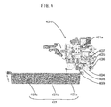
- Figs. 5 and 6 are perspective view and a side view of an outward appearance of the head section 401 which is the supplying means of a first embodiment.
- the head section 401 is provided with a head section body 401a.
- the head section body 401a includes the pocket 404, an arm 405, a first shaft 406, a second shaft 407, a guide 408 and a roller 409.
- the head section body 401a is a head body section, and the head section body 401a has various mechanisms for taking out a medication from the medication storing cases 403 and supplying the medication to a tray.
- the pocket 404 is a pocket section, the pocket 404 temporarily holds a medication received from an upper left front of the head section 401, opens at a location directly above a tray 107 to move toward a lower left side in the drawing, and places a medication on the tray 107 on the supplying side (left end of the pocket 404 in the drawing) of the pocket 404.
- An inner surface of the pocket 404 is curved so that a plurality of medications can be accommodated and held.
- the inner surface of the pocket 404 is provided with a cushioning such as a cloth or an elastic body such as rubber to prevent the medication container from being damaged.
- the pocket has any shape only if the pocket can temporarily hold a medication and can place the medication on a tray.
- the pocket may have a cylindrical cross section.
- the arm 405 is an arm section, and the arm 405 couples the head section body 401a and the pocket 404 with each other.
- the pocket 404 is turnably connected to one end of the arm 405 through the first shaft 406, and the head section body 401a is turnably connected to the other end of the arm 405 through the second shaft 407.
- the second shaft is rotated by driving means (not shown).
- the driving means is not connected to the first shaft, and the first shaft can freely rotate.
- the guide 408 is a guide section, and is provided on a side surface of the pocket 404.
- a guide surface of the guide 408 abuts against the roller 409, the guide 408 moves such that it slides on the roller 409, thereby moving the pocket 404 and opening and closing the pocket 404. That is, locus, opening and closing movements and timing of the pocket 404 depend on a shape of the guide 408.
- a surface which is in contact with the roller 409 includes a first guide surface 408a and a second guide surface 408b.
- the first guide surface 408a mainly realizes a forward movement of the pocket 404 toward a tray, and the first guide surface 408a comes into contact with the roller 409 until the first shaft 406 reaches the lowest point.
- An angle of the second guide surface 408b is smaller than that of the first guide surface 408a, and mainly realizes opening movement of the pocket 404.
- the second guide surface 408b comes into contact with the roller 409 after the first shaft 406 starts moving upward from the lowest point.
- the first guide surface 408a and the second guide surface 408b are connected to each other through a gentle curved surface such that inclinations of tangents are continued. According to this configuration, it is possible to realize smooth opening and closing movements of the pocket 404.
- the roller 409 is an abutment section, and projects downward from the head section body 401a.
- the roller 409 is provided closer to a tray than the first shaft 406, i.e., in a positive direction from the first shaft 406 along the Y axis in the drawing. In this direction, the pocket 404 moves forward.
- a tray 107 waits for a medication to be supplied by the supplying device.
- Figs. 5 and 6 show that a tray 107 waits for a medication is supplied to a region 107a. This position may be a position where the tray 107 is conveyed on the second conveyor 202, or may be a position moved by the moving means perpendicularly to the conveying direction of the tray 107.
- Figs. 7 show opening and closing movements of the pocket 404.
- a series of the movements is realized by applying a driving force to the second shaft 407 by driving means (not shown) such as a motor.
- Figs. 7(a) shows a state where the pocket 404 is accommodated in the head section body 401a, i.e., a state where the pocket 404 is closed. At that time, a bottom surface of the pocket 404 is directed horizontal, or directed slightly upward toward a supplying opening so that a held medication does not drop.
- Figs. 7(a) to 7(d) show, with broken lines, the state shown in Fig. 7(a) .
- Fig. 7 show, with broken lines, the state shown in Fig. 7(a) .
- FIG. 7(b) shows a state immediately before the pocket 404 starts opening.
- the arm 405 is turned by the second shaft 407, the arm 405 is swung forward and with this, the pocket 404 moves forward toward a tray (leftward in the drawing).
- the first shaft 406 of the arm 405 moves downward and the pocket 404 moves downward. Therefore, on the whole, it appears that the pocket moves in a left lower direction.
- a bottom surface of the pocket 404 still remains horizontally. If this state is viewed from the guide, the pocket 404 moves in the left lower direction toward a tray such that the first guide surface 408a of the guide 408 slides on the roller 409.
- Fig. 7(c) shows a state when the pocket 404 opens and a medication is to be supplied.
- the roller 409 is located at a boundary between the first guide surface 408a and the second guide surface 408b.
- the second guide surface 408b is provided at an angle close to horizontal as compared with the first guide surface 408a.
- the pocket 404 is supported by the roller 409 and the first shaft 406 and in this state, as the first shaft 406 again moves upward from the lowest point, an angle formed between the first shaft 406 and the roller 409 abruptly increases, and a supplying inlet side of the pocket 404 gradually sinks. That is, the pocket 404 starts opening, and the bottom surface of the tray 107 and the supplying opening of the pocket 404 come into contact with each other. Since the pocket 404 once sinks and then starts opening in this manner, a medication is supplied at a height from the tray 107 lower than that of the conventional technique, that is, a medication can be supplied dispensed at an angle gentler than that of the conventional technique.
- Fig. 7 (d) shows a state where the pocket is fully opened. At that time, a position of the roller 409 is on the second guide surface 408b as shown with solid lines in Fig. 7(d) . Since the first shaft 406 is moved further upward and lifts the pocket 404, the pocket 404 fully opens as shown in the drawing, and the bottom surface of the pocket 404 is directed substantially vertically.
- a medication does not remain in the pocket 404 and it is possible to reliably dispense the medication. If control is performed such that the entire head section 401 is brought upward, it is possible to dispense a medication from the pocket 404 to a tray 107 more reliably.
- Figs. 8 show movements of a tray when a medication is dispensed to the tray and a dispensing position of the medication on the tray.
- "X" shows a position where the pocket of the head dispenses the medication.
- a accommodating section of the tray 107 is divided by two partition plates into three sections, i.e., accommodating sections 107a, 107b and 107c.
- the pocket 404 moves forward from above in the drawing and a medication is placed on the accommodating section 107a of the tray 107 on a conveying path.
- the pocket 404 moves such that its supplying opening moves forward, it is unnecessary to move the tray 107 toward the pocket 404 when a medication is placed on the accommodating section 107a.
- the tray 107 is rotated by the turning means.
- the pocket 404 moves forward from above in the drawing and the medication is placed on the accommodating section 107c. In this case also, it is unnecessary to move the tray 107 toward the pocket 404.
- the tray 107 is moved toward the pocket 404 by the moving means.
- the pocket 404 moves forward and a medication is placed on the accommodating section 107b.
- the pocket 404 can move forward and the medication can be dispensed to the tray 107, the distance through which the tray 107 is moved by the moving means can be shortened, and a depth dimension of the device can be shortened. It is necessary that a moving space for the head section 401 in the Y axis direction (see Fig. 4 ) is provided only directly above the tray 107, it is possible to extend the depth dimension of the medication storing case and it is possible to store more medicines in a limited space. Lastly, as shown in Fig. 8(d) , the tray is returned to the original tray conveying path by the moving means and the orientation of the tray 107 is returned to its original orientation.
- the medications are placed on the accommodating sections 107a and 107c, the medications are received on the conveying path, but it is also possible to move the tray in a direction perpendicular to the conveying path by the moving means.
- the moving means By employing such a configuration, since the pocket and the tray come close to each other, the movement of the tray in the direction perpendicular to the tray conveying path can be suppressed to the minimum value, and it is possible to shorten the depth dimension of the medication dispensing device. More specifically, in this embodiment, since the pocket 404 comes close by 50 mm and the tray 107 comes close by 150 mm, the device itself can be thinned by 50 mm.
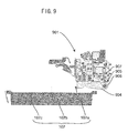
- Fig. 9 is a side view of a head 901 which is supplying means of a second embodiment. Unlike the first embodiment, the guide section and the abutment section are not provided. Only the second shaft 407 is driven in the first embodiment, but a first shaft 906 is also driven in addition to the second shaft in the second embodiment. That is, the first shaft 906 and a second shaft 907 are connected to driving means (not shown) and rotate a pocket 904 and an arm 905. Both the second shaft 907 and the first shaft 906 are driven in this manner, it is possible to freely control a forward moving amount of the pocket 904 and an angle of the pocket 904, and it is possible to realize the same operation as that of the first embodiment. Further, it is also possible to realize more complicated operation than that of the first embodiment.
- the arm 905 is rotated by the driving means connected to the second shaft 907 until the arm 905 is oriented perpendicular to a bottom surface of a tray.
- the driving means connected to the first shaft 906 is brought into synchronization with the driving means connected to the second shaft 907, and they rotate at the same speed.
- the pocket 904 can be maintained horizontally until the arm 905 reaches the lowest point.
- the rotation speed of the first shaft is gradually increased. According to this, the supplying opening side (left end of the pocket) of the pocket 904 starts lowering.
- the pocket 904 is fully opened and a medication can reliably be supplied to the tray.
- the supplying point of a medication can be set forward as compared with the conventional technique, the moving amount of the tray is reduced, it is possible to realize a thinner medication dispensing device. Since the supplying point of the medication can be set lower as compared with the conventional technique, it is possible to supply a medication to a tray using the method in which an impact applied to the medication is small.
- a third and subsequent embodiments are not for preventing damage of the medication container generated when a medication is dispensed from the supplying means to a tray, but are for supplying means to prevent damage of a medication container generated between instant when the supplying means takes out a medication from a medication storing case and instant when the medication reaches a pocket of the supplying means.
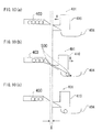
- Figs. 10 are schematic diagrams showing, in stages, medication taking out movements in the automatic medication dispensing device. This automatic medication dispensing device does not include a flap having a limited installation space, especially a limited depth dimension. As shown in Figs. 10 (a) to (c) , the head section 401 has a pocket 404 and a chute 410.
- the chute 410 functions as a path of a medication 500 when the medication 500 in the medication storing case 403 is taken out into the head section 401.
- the chute 410 of the head section 401 moves toward the medication storing case 403 (direction of arrow A).
- the medication 500 in the medication storing case 403 is made to drop into the pocket 404 through the chute 410 and is taken out as shown in Fig. 10(b) .
- the chute 410 moves in a direction separating away from the medication storing case 403 (direction of arrow B).
- Fig. 10(a) when the medication 500 in the medication storing case 403 is taken out, the chute 410 of the head section 401 moves toward the medication storing case 403 (direction of arrow A).
- the medication 500 in the medication storing case 403 is made to drop into the pocket 404 through the chute 410 and is taken out as shown in Fig. 10(b) .
- the chute 410 moves in a direction separating away from the medication storing case 40
- the chute 410 returns to its original position (same position as that shown in Fig. 10 (a) ) and the taking out operation of the medication 500 from the medication storing case 403 by the head section 401 is completed.
- a medication 500 is temporarily stopped in a chute 610 as shown in Fig. 16 (b) by sufficiently securing a moving distance X: of the chute 610, speed of the medication 500 generated when it drops into the chute 610 from the medication storing case 403 is absorbed and then, the medication 500 is taken out from the chute 610 into the pocket 604 as shown in Fig. 16(c) .
- the automatic medication dispensing device 101 having the limited depth dimension, however, when a medication 500 is taken out from the medication storing case 403, since the moving distance X of the chute 410 is limited, the medication 500 can not be absorbed in the chute 410. As a result, the medication 500 drops directly into the pocket 404 of the head section 401 from the medication storing case 403 (see Fig. 10(b) ). Therefore, since dropping speed of the medication 500 into the pocket 404 corresponds to a height of the medication storing case 403 from the pocket 404, when a plurality of medications 500 are taken out into the pocket 404, the medications 500 collide against each other and there is fear that a problem that the medications 500 become cracked.
- the head section 401 of the third embodiment is provided with a flap 411 which temporarily stops a medication 500 when it is taken out from the medication storing case 403 to the head section 401 as shown in Figs. 11 .
- the flap 411 temporarily stops a medication 500 when it is taken out from the medication storing case 403 to the head section 401 based on the prescription instruction, and after the medication 500 is temporarily stopped, the medication 500 is moved in a direction in which engagement with the medication 500 is released, thereby releasing the engagement with the medication 500 and the medication 500 is made to drop into the pocket 404.
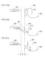
- Figs. 11 are schematic diagrams showing, in stages, medicine taking out movements of the automatic medication dispensing device of the third embodiment of the device.
- Fig. 11 (a) when a medication 500 in the medication storing case 403 is taken out, the chute 410 of the head section 401 moves in a direction approaching the medication storing case 403 (direction of arrow A1), and the flap 411 moves in a direction approaching the path for the medication 500 in the chute 410 (direction of arrow A2).
- the flap 411 moves in a direction in which the flap 411 is pushed against the chute 410 in an interlocking manner with a mechanism which opens a rear gate (not shown) of the medication storing case 403 located on the head section 401 when the head section 401 approaches the medication storing case 403. Since the flap 411 is made to stand utilizing the mechanism which opens the rear gate of the medication storing case 403 of the head section 401 in this manner, it is possible to excellently bring the movement of the head section 401 and the movement of the flap 411 into synchronization with each other. Then, as shown in Fig.
- the medication 500 which was taken out from the medication storing case 403 by the flap 411 is temporarily stopped in the chute 410, thereby absorbing the speed of the medication 500.
- the chute 410 is moved to a direction (direction of arrow B1) returning to its original position (see Fig. 11 (a) ).
- the flap 411 is also moved to a direction (direction of arrow B2) returning to its original position (see Fig. 11(a) ). More specifically, in a state where the head section 401 is separated away from the medication storing case 403, the flap 411 is in a state where it is biased by a spring and separated away from the chute 410.
- the flap 411 is automatically moved in the direction in which it is biased by a spring provided on a later-described hinge 412 and the flap 411 is opened. If the flap 411 is moved to jump up in the direction of arrow B2, the engagement between the flap 411 and the medication 500 is released as shown in Fig. 11(c) , and the medication 500 can reliably be made to drop into the pocket 404.
- a medication 500 is temporarily stopped in the chute 410 in this manner. According to this, the speed of the medication 500 which drops into the pocket 404 of the head section 401 can be reduced. Therefore, when a plurality of medications 500 are to be taken out into the pocket 404, it is possible to avoid a case where the medications 500 collide against each other and they are damaged. If the flap 411 automatically moves in accordance with movement of the chute 410, it is possible to reliably drop, into the pocket 404, a medication 500 which was temporarily held in the chute 410 when the medication 500 is dispensed.
- the flap 411 is moved through the hinge 412 which is biased by the spring (not shown) in synchronization with the movement of the chute 410 in this embodiment, the flap 411 may be moved in synchronization with movement of the entire head section 401 of course.
- the flap is always biased toward the medication storing case 403 through a resilient member such as a spring via the hinge 412, and when the head section 401 is disengaged from the medication storing case 403, the flap 411 is moved to jump up the flap 411. At that time, after sufficient time during which a medication 500 drops into the pocket 404 is elapsed, the flap 411 may be moved toward the medication storing case 403.
- Fig. 12 is a side view showing a state where one of side surfaces is removed for explaining an interior structure of the head section 401.
- Fig. 12 shows a state where the medication 500 shown in Fig. 11(b) is temporarily stopped in the chute 410. As shown in Fig. 12 , if the flap 411 is held at a predetermined position, the medication 500 can temporarily be stopped on the chute 410. If the flap 411 is moved such that an end 411B of a lower side of the flap 411 jumps up, engagement between the flap 411 and the medication 500 can be released and the medication 500 can drop into the pocket 404.
- the flap 411 in the third embodiment is hinged to the head section 401 by the hinge 412 as holding means in an upper end 411A which is opposite from an end 411B of the flap 411. Hence, the flap 411 can turn around a portion thereof which is hinged on the head section 401 by the hinge 412.
- the flap 411 of the third embodiment is held by the hinge 412 at a position where a medication 500 is temporarily stopped in the chute 410 or at a position where engagement between the flap 411 and the medication 500 is released and the medication 500 can drop into the pocket 404 in accordance with a stage of the taking out operation of the medication 500.
- Means for driving the flap 411 may be integrally formed with the hinge 412, or may be formed as an independent member.
- the taking out speed of a medication into the supplying means can sufficiently be reduced. Therefore, when a plurality of medications 500 are to be taken out into the supplying means, it is possible to avoid a case where the medications collide against each other and they are damaged. In the dispensing operation of a medication, it is possible to reliably avoid such an error that a taken out medication can not open the flap by its own weight and does not drop into the supplying means and the medication is not dispensed, and such an error that a medication which did not drop is dispensed when another medication for other patient is dispensed.
- the head section 401 having the flap 411 is described in the third embodiment, but in a fourth embodiment, an automatic medication dispensing device 101 having a movable section 413 in addition to the flap 411 will be described. Since an entire configuration of the automatic medication dispensing device is the same as that of the third embodiment, explanation thereof will be omitted. Members having the same functions as those described above are designated with the same numbers and explanation thereof will be omitted.
- Figs. 13 are schematic diagram showing, in stages, medication taking out movements of the automatic medication dispensing device of the fourth embodiment of the invention.
- Fig. 13(a) when a medication 500 in the medication storing case 403 is taken out, the chute 410 moves in a direction (direction of arrow A1) approaching the medication storing case 403, the flap 411 moves in a direction (direction of arrow2) approaching a path for the medication 500 in the chute 410, and the movable section 413 moves upward (direction of arrow A3).
- a medication 500 taken out from the medication storing case 403 is temporarily stopped by the flap 411 and the movable section 413, thereby absorbing its speed.
- the flap 411 and the movable section 413 return to their original positions ( Fig. 13(a) ) after a medication 500 is temporarily stopped, they move in the directions shown with the arrow B1, B2 and B3. By this movement, the engagement between the flap 411, the movable section 413 and the medication 500 is released, and the medication 500 can drop into the pocket 404.
- the dropping speed of the medication 500 into the pocket 404 of the head section 401 can be reduced. Therefore, when a plurality of medications 500 are to be taken out into the pocket 404, it is possible to avoid a case where the medications collide against each other and they are damaged.
- Positions of the flap 411 and the movable section 413 are changed in accordance with the movement of the chute 410, that is, an inclination angle of the movable section 413 is changed in an interlocking manner with movement of the flap 411.
- the inclination angle of the movable section 413 is an angle formed between a horizontal surface and a straight line which connects a portion of the movable section 413 where a medication 500 is temporarily stopped and an end 413B (see Fig. 14 ) of the movable section 413 with each other.
- a surface of the movable section 413 is oriented horizontally, i.e., an inclination angle of the movable section 413 is set to 0°, and the surface of the movable section 413 is inclined such that its end 413B is moved downward in an interlocking manner with the movement of the flap 411. According to this, in the dispensing operation of the medication 500, it is possible to reliably drop, into the pocket 404, a medication 500 which is temporarily held in the chute 410.
- the inclination angle of the movable section 413 is set to 0° in a state where a medication 500 is temporarily stopped in the chute 410 and is set to 30° in an interlocking manner with the movement of the flap 411, but the inclination angle is not limited to this and the inclination angle can appropriately be set.
- a fact that the inclination angle of the movable section 413 is changed in the interlocking manner with the movement of the flap 411 means that the inclination angle of the movable section 413 is changed while a medication 500 which is temporarily held in the chute 410 by the flap 411 exists on the movable section 413. Therefore, the invention is not limited to a configuration that the inclination angle of the movable section 413 is changed simultaneously with the movement of the flap 411, and it is possible to employ a configuration that the flap 411 moves after the inclination angle of the movable section 413 is changed, or a configuration that the flap 411 moves before the inclination angle of the movable section 413 is changed.
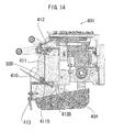
- Fig. 14 is a side view showing a state where one of side surfaces is removed for explaining an interior structure of the head section 401.
- Fig. 14 shows a state where a medication 500 shown in Fig. 13(b) is temporarily stopped in the chute 410. As shown in Fig. 14 , it is possible to temporarily stop the medication 500 by holding the flap 411 and the movable section 413 at predetermined positions. From the state shown in Fig.
- the movable section 413 of the fourth embodiment is a plate body on which a medication 500 can be placed.
- the end 413B is movable in the vertical direction such that the end 413B on the side where the movable section 413 passes when the medication 500 drops into the pocket 404 comes lower than a portion thereof where the medication 500 is placed.
- the path through which a medication 500 is taken out from the medication storing case 403 to the head section 401 is provided with the movable section 413, and the end 413B of the movable section 413 moves downward in the interlocking manner with the movement of the flap 411. That is, the automatic medication dispensing device of this embodiment includes the movable section which swings together with the flap as means for stopping a medication, and the speed of a medication when it is taken out to the supplying means can sufficiently be reduced. Therefore, when a plurality of medications is to be taken out into the supplying means, it is possible to avoid a case where the medications collide against each other and they are damaged.
- Figs. 15 are schematic diagram showing, in stages, medication taking out movements of the automatic medication dispensing device of the fifth embodiment of the invention. As shown in Fig.
- the chute 410 moves in a direction (direction of arrow A1) approaching the medication storing case 403.
- the flap 411 of the fifth embodiment is hinged to the head section 401 such that its end 411B on the side of the chute 410 can freely turn.
- the flap 411 does not have means which drives the flap 411 to hold the end 411B at a predetermined position, but the flap 411 is provided at a position where it comes into contact with a medication 500 when the medication 500 in the medication storing case 403 is taken out to the head section 401.
- the medication 500 taken out from the medication storing case 403 comes into contact with the flap 411 in the chute 410, and the medication 500 moves such that its one end jumps up. At that time, it is possible to reduce the speed of the medication 500 by a value corresponding to energy consumed for jumping the flap 411 up.
- the flap 411 By providing the flap 411 at the position where it comes into contact with a medication 500, the dropping speed of the medication 500 into the pocket 404 of the head section 401 can be reduced. Therefore, when a plurality of medications 500 are to be taken out into the pocket 404, it is possible to avoid a case where the medications collide against each other and they are damaged.
- By appropriately adjusting size, weight and resistance against turning motion of the flap 411 in accordance with weight of a medication 500 it is possible to reliably avoid such an error that a taken out medication 500 can not open the flap by its own weight and does not drop into the supplying means and the medication is not dispensed, and such an error that a medication which did not drop is dispensed when another medication for other patient is dispensed.
- the present invention can be utilized as the automatic medication dispensing device in a hospital and in addition, the invention can also be utilized as a device which accommodates various kinds of articles in a fractionation manner in accordance with predetermined information.
Landscapes
- Physics & Mathematics (AREA)
- General Physics & Mathematics (AREA)
- Medical Preparation Storing Or Oral Administration Devices (AREA)
- Specific Conveyance Elements (AREA)
Abstract
Description
- The present invention relates to an automatic medication dispensing device which dispenses a medicine based on a prescription instruction in a hospital or the like.
- An automatic medication dispensing device automatically dispenses a medicine in accordance with a prescription to a tray which is prepared for each patient. The automatic medication dispensing device is provided with a medication supplying unit which stores medicines in an accommodating section, and which dispenses the medicine based on a prescription instruction. The medication supplying unit is provided with supplying means which takes out a desired medicine from the accommodating section, and dispenses the medicine to a tray, and supplying means having various ingenuities have been disclosed in the past (
patent document 1 and patent document 2). -
- [Patent Document 1] Japanese Patent Application Laid-open No.
2007-209599 - [Patent Document 2] Japanese Patent Application Laid-open No.
2003-81429 - However, the automatic medication dispensing device inevitably becomes large in size and a large installation space is required because it is necessary to accommodates a large number of medicines and the device requires places where vacant trays as many as the number of patients are prepared and stored and where trays to which medicines are dispensed are accommodated. Further, if various functions are added, a depth dimension of the device is increased and this is a cause of increase in the installation space. Especially in a medium-scale hospital having about 200 to 400 beds, the automatic medication dispensing device exerts effect if the automatic medication dispensing device is introduced, but there is a problem that the device can not be introduced due to the installation space. Hence, an automatic medication dispensing device requiring a small installation space is desired.
The automatic medication dispensing device also dispenses a medicine which is accommodated in an easily breakable container and which must be handled with the greatest care such as an injection ampule and an instilment bag. In the automatic medication dispensing device, one of procedures in which a medicine container is prone to be damaged is a step of taking out a medicine to a step of supplying the medicine to a tray. Therefore, it is desired to realize supplying means which does not easily damage a medicine. - Hence, it is an object of the present invention to provide an automatic medication dispensing device requiring a small installation space especially a small depth dimension. In addition, it is an object of the invention to provide an automatic medication dispensing device having supplying means which does not easily damage a medicine container.
- According to an invention described in
claim 1, there is provided an automatic medication dispensing device having supplying means which supplies accommodated medications to a tray based on the prescription instruction, wherein the supplying means includes a head body section, a pocket section which temporarily holds a taken out medication and which places the medication on the tray, and an arm section which couples the head body section and the pocket section to each other, the pocket section is turnably connected to one end of the arm section through a first shaft, and the other end of the arm section and the head body section are turnably connected to each other through a second shaft.
Here, it is only necessary that the "pocket section" can temporarily hold a taken out medicine and its shape is not limited. It is only necessary that the "arm section" can connect the head body and the pocket section with each other, its shape is not limited and the arm section need not be of a plate-shape or a rod-shape.
According to an invention described in claim 2, in the automatic medication dispensing device ofclaim 1, an abutment section is provided at a position of the head body section closer to the tray than the first shaft, the pocket section is provided with a guide section, the guide section abuts against the abutment section and in this state, the pocket section places a medication on the tray.
According to an invention described in claim 3, in the automatic medication dispensing device of claim 2, the guide section includes a first guide surface and a second guide surface which is continuous with the first guide surface and which has a curvature or an angle different from that of the first guide surface.
According to an invention described in claim 4, in the automatic medication dispensing device ofclaim 1, 2 or 3, the device comprises tray conveying means which conveys the tray, the tray conveying means includes moving means which moves the tray toward the pocket section when a medication is placed on the tray.
According to an invention described in claim 5, in the automatic medication dispensing device ofclaim 1, 2 or 3, the device further comprises tray conveying means which conveys the tray, the tray conveying means includes turning means which rotates the tray in a horizontal direction.
According to an invention described in claim 6, there is provided an automatic medication dispensing device including supplying means which temporarily holds medications accommodated in a medication storing case and then dispenses the medication to a tray based on a prescription instruction, wherein the automatic medication dispensing device includes a flap provided at a position where the flap comes into contact with the medication when the medication is taken out from the medication storing case to the supplying means.
Here, the "flap" is a cloth body or a plate body whose one end is connected to the supplying means, and it is necessary that the flap can move in a direction in which a medicine moves when the medicine is taken out from the medication storing case to the supplying means.
According to an invention described in claim 7, in the automatic medication dispensing device of claim 6, when the medication in the medication storing case is taken out to the supplying means based on a prescription instruction, the medication is temporarily stopped by the flap, and after the medication is temporarily stopped, the flap is moved, thereby releasing engagement between the medication and the flap to drop the medication into the supplying means.
According to an invention described in claim 8, in the automatic medication dispensing device of claim 7, the device further comprises holding means which holds the flap at a position where the medication is temporarily stopped and a position where engagement with respect to the medication is released when the medication in the medication storing case is taken out to the supplying means.
According to an invention described in claim 9, in the automatic medication dispensing device of claim 7 or 8, the device further comprises a movable section at a path where the medication is taken out from the medication storing case, an inclination angle of the movable section is changed in an interlocking manner with movement of the flap. - According to the invention described in
claim 1, since the automatic medication dispensing device includes the arm section, when a medication is placed on the tray, i.e., when a medication is dispensed, the pocket section can be moved toward a tray located more forward. That is, it is unnecessary to move the tray toward the head body section, or even if the tray is moved, its moving distance can be shortened, depth dimension of the automatic medication dispensing device can be shortened, and it is possible to realize an automatic medication dispensing device requiring a small installation area. Since the automatic medication dispensing device has the arm section, it is possible to supply a medication from a location lower than that of the conventional technique, it is possible to supply a medication to the tray by a method having a smaller impact, and it is possible to prevent a medication from being damaged.
According to the invention described in claim 2, the guide section and the abutment section are provided. According to this, it is possible to move the pocket section toward a tray located more forward than the abutment section, and to dispense a medication to the tray. That is, it is unnecessary to move the tray toward the head body section, or even if the tray is moved, its moving distance can be shortened, depth dimension of the automatic medication dispensing device can be shortened, and it is possible to realize an automatic medication dispensing device requiring a small installation area. Further, since the abutment section is provided at the position in front of the first shaft, it is possible to reduce the angle of the bottom surface of the pocket section with respect to the tray when a medication is to be dispensed, and even if a medication is accommodated in a breakable medication container, the medication can be moved to the tray slowly, and it is possible to realize supplying means having less possibility of damage of the medication container.
According to the invention described in claim 3, since the guide section is provided a guide surface having a plurality of curvatures or angles, operation of the pocket section can be changed. For example, the pocket section is first moved to a location directly above the tray and then, a medication is moved to the tray at a gentle angle between the bottom surface of the pocket section and a bottom surface of the tray, and medications can reliably be transferred to the trays without allowing medications to remain in the pocket section while increasing the angle.
According to the invention described in claim 4, since the tray can be moved toward the head body section, the pocket section and the tray come close to each other and hence, it is possible to dispense a medication more swiftly. The moving distance to the tray toward the depth dimension can be shortened by moving the pocket section toward the forward tray. Therefore, it is possible to shorten the depth dimension of the automatic medication dispensing device, and it is possible to realize an automatic medication dispensing device requiring a small installation area.
According to the invention described in claim 5, since the tray can be rotated, even when a medication is to be placed on a region of the tray farthest away from the pocket section, the medication can be placed on the tray by rotating the tray without moving the tray by the moving means. According to this, since the moving distance of the tray in the depth dimension direction can be shortened, the depth dimension of the automatic medication dispensing device can be shortened, and it is possible to realize an automatic medication dispensing device requiring a small installation area.
According to the invention described in claim 6, when a medication is taken out so that the medication is temporarily held by the supplying means, the medication comes into contact with the flap and the flap is jumped up in a direction in which a barycenter of the flap becomes high and according to this, the speed of the medication can be reduced. Therefore, when a plurality of medications is taken out into the supplying means, it is possible to avoid a case where the medications collide against each other and the medications are damaged.
Further, if material, shape, size of the flap and a coupling method with respect to the supplying means are appropriately adjusted in accordance with weight and shape of medications, the taken out medication comes into contact with the flap and the speed of the medication can sufficiently be reduced, and it is possible to open the flap by the weight of the medication its own, and to reliably drop the medication into the supplying means.
According to the invention described in claim 7, a medication is temporarily stopped by the flap and the speed of the medication can be brought into zero. After the speed of the medication taken out from the medication storing case is brought into zero, the engagement between the flap and the medication is released and the medication is made to drop into the supplying means. Therefore, the speed of the medication dropping into the supplying means does not correspond to a position of the medication storing case but corresponds to a position where the medication is temporarily stopped. According to this, the height from the supplying means can be lowered and the speed of the medication dropping into the supplying means can be reduced and thus, it is possible to prevent the medication from being damaged.
After the medication is temporarily stopped by the flap, the engagement with respect to the flap is released and the medication is made to drop into the supplying means. Hence, in the dispensing operation of the medication, it is possible to reliably avoid such an error that a taken out medication can not open the flap by its own weight and does not drop into the supplying means and the medication is not dispensed, and such an error that a medication which did not drop is dispensed when another medication for other patient is dispensed.
According to the invention described in claim 8, the flap can be held at a predetermined position by the holding means. Hence, it is possible to release the engagement between a medication and the flap and to reliably drop the medication into the supplying means by reliably and temporarily stopping the medication and releasing the flap-holding state by the holding means.
According to the invention described in claim 9, a medication is temporarily stopped by the flap and the movable section whose inclination angle is changed in the interlocking manner with the movement of the flap, and the speed of the medication taken out into the supplying means can sufficiently be reduced. Therefore, even when a plurality of medications are to be taken out into the supplying means, it is possible to avoid a case where the medications collide against each other and the medications are damaged. -
-
Fig. 1 is a front view of an automatic medication dispensing device of the present invention; -
Fig. 2 is a perspective view of an outward appearance of a tray conveying unit of the device; -
Fig. 3 is a configuration diagram of an essential portion of the tray conveying unit of the device; -
Fig. 4 is a side view of an interior of a medication supplying unit of the device; -
Fig. 5 is a perspective view of an outward appearance of supplying means of a first embodiment of the device; -
Fig. 6 is a side view of the supplying means of the first embodiment of the device; -
Figs. 7 are explanatory diagrams showing movements of a pocket section configuring the supplying means of the first embodiment of the device; -
Figs. 8 are explanatory diagrams showing movements of a tray of the device; -
Fig. 9 is a side view of supplying means of a second embodiment of the device; -
Figs. 10 are schematic diagrams showing, in stages, medication taking out movements when a medication supplying unit does not have a flap; -
Figs. 11 are schematic diagrams showing, in stages, medicine taking out movements of a third embodiment of the device; -
Fig. 12 is a side view showing a state where one of side surfaces is removed for explaining an interior structure of a medication supplying unit of a automatic medication dispensing device of the third embodiment of the device; -
Figs. 13 are schematic diagram showing, in stages, medication taking out movements of a fourth embodiment of the device; -
Fig. 14 is a side view showing a state where one of side surfaces is removed for explaining an interior structure of a medication supplying unit of a fourth embodiment of the device; -
Figs. 15 are schematic diagram showing, in stages, medication taking out movements of a fifth embodiment of the device; and -
Figs. 16 are schematic diagram showing, in stages, medication taking out movements of supplying means of a conventional automatic medication dispensing device. -
- 101
- automatic medication dispensing device
- 102
- non-accommodated tray unit
- 103
- medication supplying unit
- 104
- printer unit
- 105
- accommodated tray unit
- 106
- tray conveying means
- 107
- tray
- 201
- first conveyor
- 202
- second conveyor
- 203
- third conveyor
- 401, 901
- head
- 401a
- head body
- 403
- medication storing case
- 404, 904
- 405, 905
- arm
- 406, 906
- first shaft
- 407, 907
- second shaft
- 408
- guide
- 409
- rollers
- 410
- chute
- 411
- flap
- 412
- hinge
- 413
- movable section
- 500
- medication
- Concerning an exemplary example of the present invention, a structure of an entire automatic medication dispensing device of the present invention having supplying means which supplies an accommodated medication to a tray based on a prescription instruction will be described with reference to
Fig. 1 .
Fig. 1 is a front view of an outward appearance of an automaticmedication dispensing device 101. The automaticmedication dispensing device 101 includes anon-accommodated tray unit 102, amedication supplying unit 103, aprinter unit 104, an accommodatedtray unit 105 and tray conveying means 106 which connect these units to one another.
Thenon-accommodated tray unit 102 loads and accommodatesvacant trays 107 on which various medications are placed, and supplies vacant trays to thetray conveying means 106. In this embodiment, the vacanttray accommodating unit 102 is provided at its front surface with a door made of clear plastic or glass so that stock of trays can be checked, but this cover is not absolutely required and thetrays 107 may be loaded and accommodated such that the trays are exposed.
Themedication supplying unit 103 stores various kinds of medications in a fractionation manner, and supplies and places a medication which is necessary for each patient to and on avacant tray 107 conveyed from thenon-accommodated tray unit 102 by the tray conveying means 106 based on a prescription instruction such as prescription data. The medication supplying unit includes a large number of medication cases in which medications are stored by kinds, and supplying means which takes out a desired medication from the medication case based on the prescription instruction by placing the medication on the tray. Details thereof will be described later. It is only necessary that medications are to be prescribed, and examples of the medications are injection drug, drops, internal medicine, medical plaster, suppository and the like. Typical packages of medications themselves are an ampule and a plastic bottom in the case of injection drug, a transfusion bag in the case of the drops, and a small bottle or a SP packet in the case of internal use tablet or powdered medicine.
Theprinter unit 104 includes a printer for printing a prescription on which contents of medicine prescription such as an injection label or printing medication labels of various kinds of medicines are described. Theprinter unit 104 supplies and places the printed prescription and a medication label to and on atray 107 conveyed from themedication supplying unit 103 by thetray conveying means 106. In this embodiment, a front surface of the printer unit is covered with an opaque metal or plastic door to prevent dust and foreign matter from entering from outside and the door can be opened and closed. Individual information is described on a printed matter printed by the printer, and confidentiality thereof is high. Hence, individual certification means may be provided and the door may be opened and closed. Positions of themedication supplying unit 103 and theprinter unit 104 may be reversed.
The accommodatedtray unit 105 receives, loads and accommodates atray 107 conveyed from theprinter unit 104 by thetray conveying means 106. At this point, various kinds of medications, injection labels and medication labels are placed on thetrays 107. Like thenon-accommodated tray unit 102, the accommodatedtray unit 105 is also provided at its front surface with a door made of clear plastic or glass so that accommodated strays can be checked. According to this configuration, it is possible to prevent atray 107 on which a medicine is placed from being destroyed and to prevent the medicine from being damaged. However, these covers are not absolutely required in terms of function, and thetrays 107 may be placed and accommodated such that they are exposed. Atray 107 placed on the accommodatedtray unit 105 is transferred to a cart or the like, and conveyed to a doctor or a patient by a nurse or a pharmacist.
The tray conveying means 106 connect thenon-accommodated tray unit 102 to the accommodatedtray unit 105 through themedication supplying unit 103 and theprinter unit 104 by means such as belt conveyers. According to this embodiment, the tray conveying means 106 are independently provided on lower portion of these units. The tray conveying means receives avacant tray 107 from thenon-accommodated tray unit 102, the tray conveying means receives a medication from themedication supplying unit 103, the tray conveying means receives a prescription and a medication label from theprinter unit 104 onto thetray 107, and thetray 107 on which the medicine and the prescription are placed is delivered to the accommodatedtray unit 105. By providing these tray conveying means 106 on a line, trays can be disposed, medications can be supplied, printed matters can be supplied, and trays can be delivered by each unit simultaneously in parallel, and it is possible to realize more swift dispensation. Detailed configuration and movements of the tray transferring means 106 will be described later. - A configuration of the tray conveying means will be described using
Figs. 2 and3 .Fig. 2 is a perspective view of an outward appearance of the tray conveying means of a lower portion of the medication supplying unit.Fig. 3 is a configuration diagram of a second conveyor of the tray conveying means which can turn. AlthoughFigs. 2 and3 show a configuration when trays are conveyed from right to left, but the trays may be conveyed from left to right depending upon a space of a hospital.
The tray conveying means 106 located at a lower portion of themedication supplying unit 103 includes a combination of a plurality of belt conveyors. That is, the tray conveying means 106 includes afirst conveyor 201, asecond conveyor 202 and athird conveyor 203.
Thefirst conveyor 201 includes rollers, a belt and a motor for driving the rollers, thefirst conveyor 201 receives a command from a control device such as a computer (not shown) to drive the motor, and conveys trays. Thefirst conveyor 201 is located upstream of themedication supplying unit 103, receives atray 107 which flows from a side of thenon-accommodated tray unit 102, and delivers the tray to thesecond conveyor 202. Whentrays 107 stagnate on thesecond conveyor 202, it is possible to control such that thetrays 107 wait on thefirst conveyor 201.
An electroniccard writing device 204 is provided at an intermediate portion of thefirst conveyor 201, patient information such as date, name of patient, hospital ward, hospital room and patient ID is written on anelectronic card 401 which is a patient card provided on a side surface of atray 107, and the information is displayed by display means on the electronic card. Information such as contents of prescription and kinds of prescribed medicine may be written at the same time. The electroniccard writing device 204 may be provided on thethird conveyor 203 or the tray conveying means 106 of a lower portion of theprinter unit 104. Thesecond conveyor 202 is located between thefirst conveyor 201 and thethird conveyor 203, receives a tray from thefirst conveyor 201, and delivers the tray to thethird conveyor 203. Thesecond conveyor 202 corresponds to moving means and turning means. Thesecond conveyor 202 itself moves in a direction perpendicular to a conveying direction of a tray, or thesecond conveyor 202 itself turns. The supplying means is provided on the second conveyor, and the supplying means dispenses a medication to a region of a desired tray by combining the moving means and the turning means.
A detailed configuration of thesecond conveyor 202 will be described usingFig. 3 . Thesecond conveyor 202 functions as the moving means which moves a tray toward the supplying means, and as the turning means which rotates a tray. The moving means and the turning means are not limited to the following means only if they can move a tray in a direction perpendicular to the conveying direction or can rotate a tray.
Thesecond conveyor 202 includesrollers 205,belts 206 and amotor 207. A driving force of themotor 207 is transmitted to therollers 205, theendless belts 206 are rotated, thereby conveying atray 107 on upper ends of thebelts 206. Thesecond conveyor 202 also includes aturning section 208, amotor 209, abelt 210 androllers 211. A driving force of themotor 209 is transmitted to theturning section 208 through thebelt 210 and therollers 211, theturning section 208 turns, thereby rotating the entiresecond conveyor 202 in the horizontal direction together with a tray placed on the upper portion. Thesecond conveyor 202 is provided with amotor 212, aball screw 213, and arail member 214. A driving force of themotor 212 is transmitted to theball screw 213, rotation movement of themotor 212 is converted into straight movement, and the entiresecond conveyor 202 can move in a direction (direction of arrow inFig. 3 ) perpendicular to a conveying path of a tray extending from thefirst conveyor 201 to thethird conveyor 203.
Like thefirst conveyor 201, thethird conveyor 203 also includes rollers, belts and a motor for driving the rollers, thethird conveyor 203 receives a command from a control device (not shown) such as a computer and drives the motor, and conveys a tray. Thethird conveyor 203 is located downstream of themedication supplying unit 103, and delivers atray 107 on which a medication is placed to a conveyor provided at lower portions of theprinter unit 104 and the accommodatedtray unit 105. - Details of the supplying means in the medication supplying unit of the automatic medication dispensing device of the invention will be described using
Figs. 4 to 6 .
Fig. 4 is a side view of an interior of the medication supplying unit of the automatic medication dispensing device. InFig. 4 , a deep side vertical direction on the sheet is X direction, a downward direction of the sheet is Z direction, and a leftward direction is Y direction. The medication supplying unit includes ahead section 401 which takes out a medication from the medication storing case and conveys the medication to atray 107, ahead conveying section 402 which conveys a medication by moving thehead section 401 in XZ direction, and a plurality ofmedication storing cases 403 which store medications by kinds.
Thehead section 401 is moved to themedication storing case 403 which stores a desired medication by thehead conveying section 402 based on the prescription instruction from a computer (not shown), receives the medication, and is again moved to a location directly above atray 107 by thehead conveying section 402, and places the medication on thetray 107, i.e., dispenses the medication. When the medication is dispensed, apocket 404 of thehead section 401 has such a configuration thatpocket 404 moves forward toward thetray 107 as will be described later with reference toFig. 7 . Therefore, a space in which thehead section 401 rides on thehead conveying section 402 and moves can be made small, themedication storing cases 403 can be extended rearward correspondingly and therefore, more medications can be stored. A configuration of thehead section 401 will be described based on the following embodiments. -
Figs. 5 and6 are perspective view and a side view of an outward appearance of thehead section 401 which is the supplying means of a first embodiment.
Thehead section 401 is provided with ahead section body 401a. Thehead section body 401a includes thepocket 404, anarm 405, afirst shaft 406, asecond shaft 407, aguide 408 and aroller 409.
Thehead section body 401a is a head body section, and thehead section body 401a has various mechanisms for taking out a medication from themedication storing cases 403 and supplying the medication to a tray.
Thepocket 404 is a pocket section, thepocket 404 temporarily holds a medication received from an upper left front of thehead section 401, opens at a location directly above atray 107 to move toward a lower left side in the drawing, and places a medication on thetray 107 on the supplying side (left end of thepocket 404 in the drawing) of thepocket 404. An inner surface of thepocket 404 is curved so that a plurality of medications can be accommodated and held. Preferably, the inner surface of thepocket 404 is provided with a cushioning such as a cloth or an elastic body such as rubber to prevent the medication container from being damaged. The pocket has any shape only if the pocket can temporarily hold a medication and can place the medication on a tray. For example, the pocket may have a cylindrical cross section.
Thearm 405 is an arm section, and thearm 405 couples thehead section body 401a and thepocket 404 with each other. Thepocket 404 is turnably connected to one end of thearm 405 through thefirst shaft 406, and thehead section body 401a is turnably connected to the other end of thearm 405 through thesecond shaft 407. The second shaft is rotated by driving means (not shown). In this embodiment, the driving means is not connected to the first shaft, and the first shaft can freely rotate.
Theguide 408 is a guide section, and is provided on a side surface of thepocket 404. A guide surface of theguide 408 abuts against theroller 409, theguide 408 moves such that it slides on theroller 409, thereby moving thepocket 404 and opening and closing thepocket 404. That is, locus, opening and closing movements and timing of thepocket 404 depend on a shape of theguide 408. In this embodiment, a surface which is in contact with theroller 409 includes afirst guide surface 408a and asecond guide surface 408b. Thefirst guide surface 408a mainly realizes a forward movement of thepocket 404 toward a tray, and thefirst guide surface 408a comes into contact with theroller 409 until thefirst shaft 406 reaches the lowest point. An angle of thesecond guide surface 408b is smaller than that of thefirst guide surface 408a, and mainly realizes opening movement of thepocket 404. Thesecond guide surface 408b comes into contact with theroller 409 after thefirst shaft 406 starts moving upward from the lowest point. Thefirst guide surface 408a and thesecond guide surface 408b are connected to each other through a gentle curved surface such that inclinations of tangents are continued. According to this configuration, it is possible to realize smooth opening and closing movements of thepocket 404.
Theroller 409 is an abutment section, and projects downward from thehead section body 401a. Theroller 409 is provided closer to a tray than thefirst shaft 406, i.e., in a positive direction from thefirst shaft 406 along the Y axis in the drawing. In this direction, thepocket 404 moves forward.
Atray 107 waits for a medication to be supplied by the supplying device.Figs. 5 and6 show that atray 107 waits for a medication is supplied to aregion 107a. This position may be a position where thetray 107 is conveyed on thesecond conveyor 202, or may be a position moved by the moving means perpendicularly to the conveying direction of thetray 107. - Movements of the
head section 401 having the above-described configuration will be described usingFigs. 7 .
Figs. 7 show opening and closing movements of thepocket 404. A series of the movements is realized by applying a driving force to thesecond shaft 407 by driving means (not shown) such as a motor.
Figs. 7(a) shows a state where thepocket 404 is accommodated in thehead section body 401a, i.e., a state where thepocket 404 is closed. At that time, a bottom surface of thepocket 404 is directed horizontal, or directed slightly upward toward a supplying opening so that a held medication does not drop.Figs. 7(a) to 7(d) show, with broken lines, the state shown inFig. 7(a) .
Fig. 7(b) shows a state immediately before thepocket 404 starts opening. As shown with solid lines inFig. 7(b) , if thearm 405 is turned by thesecond shaft 407, thearm 405 is swung forward and with this, thepocket 404 moves forward toward a tray (leftward in the drawing). At the same time, thefirst shaft 406 of thearm 405 moves downward and thepocket 404 moves downward. Therefore, on the whole, it appears that the pocket moves in a left lower direction. However, in this state, a bottom surface of thepocket 404 still remains horizontally. If this state is viewed from the guide, thepocket 404 moves in the left lower direction toward a tray such that thefirst guide surface 408a of theguide 408 slides on theroller 409. According to this, since thepocket 404 has moved toward the tray, it is unnecessary to move thetray 107 toward thehead section 401 using the moving means, or even if thetray 107 is moved toward thehead section 401, the moving distance becomes shorter. Since thepocket 404 has also moved downward, it is possible to supply a medication at a gentler angle as compared with the conventional technique.
Fig. 7(c) shows a state when thepocket 404 opens and a medication is to be supplied. As shown with solid lines inFig. 7 (c) , theroller 409 is located at a boundary between thefirst guide surface 408a and thesecond guide surface 408b. Thesecond guide surface 408b is provided at an angle close to horizontal as compared with thefirst guide surface 408a. Thepocket 404 is supported by theroller 409 and thefirst shaft 406 and in this state, as thefirst shaft 406 again moves upward from the lowest point, an angle formed between thefirst shaft 406 and theroller 409 abruptly increases, and a supplying inlet side of thepocket 404 gradually sinks. That is, thepocket 404 starts opening, and the bottom surface of thetray 107 and the supplying opening of thepocket 404 come into contact with each other. Since thepocket 404 once sinks and then starts opening in this manner, a medication is supplied at a height from thetray 107 lower than that of the conventional technique, that is, a medication can be supplied dispensed at an angle gentler than that of the conventional technique. Therefore, an impact applied to a medication can be reduced and it is possible to prevent the medication from being damaged. Since thepocket 404 starts opening in a state where it moves forward, it is unnecessary to move thetray 107 toward the head, or even if thetray 107 is moved, its moving distance can be minimized.
Fig. 7 (d) shows a state where the pocket is fully opened. At that time, a position of theroller 409 is on thesecond guide surface 408b as shown with solid lines inFig. 7(d) . Since thefirst shaft 406 is moved further upward and lifts thepocket 404, thepocket 404 fully opens as shown in the drawing, and the bottom surface of thepocket 404 is directed substantially vertically. According to this, a medication does not remain in thepocket 404 and it is possible to reliably dispense the medication. If control is performed such that theentire head section 401 is brought upward, it is possible to dispense a medication from thepocket 404 to atray 107 more reliably. -
Figs. 8 show movements of a tray when a medication is dispensed to the tray and a dispensing position of the medication on the tray. In the drawings, "X" shows a position where the pocket of the head dispenses the medication.
A accommodating section of thetray 107 is divided by two partition plates into three sections, i.e.,accommodating sections
First, as shown inFig. 8(a) , thepocket 404 moves forward from above in the drawing and a medication is placed on theaccommodating section 107a of thetray 107 on a conveying path. As described above, since thepocket 404 moves such that its supplying opening moves forward, it is unnecessary to move thetray 107 toward thepocket 404 when a medication is placed on theaccommodating section 107a.
Next, as shown inFig. 8(b) , thetray 107 is rotated by the turning means. Thepocket 404 moves forward from above in the drawing and the medication is placed on theaccommodating section 107c. In this case also, it is unnecessary to move thetray 107 toward thepocket 404.
As shown inFig. 8(c) , thetray 107 is moved toward thepocket 404 by the moving means. Thepocket 404 moves forward and a medication is placed on theaccommodating section 107b. Since thepocket 404 can move forward and the medication can be dispensed to thetray 107, the distance through which thetray 107 is moved by the moving means can be shortened, and a depth dimension of the device can be shortened. It is necessary that a moving space for thehead section 401 in the Y axis direction (seeFig. 4 ) is provided only directly above thetray 107, it is possible to extend the depth dimension of the medication storing case and it is possible to store more medicines in a limited space.
Lastly, as shown inFig. 8(d) , the tray is returned to the original tray conveying path by the moving means and the orientation of thetray 107 is returned to its original orientation.
When medications are placed on theaccommodating sections
By employing such a configuration, since the pocket and the tray come close to each other, the movement of the tray in the direction perpendicular to the tray conveying path can be suppressed to the minimum value, and it is possible to shorten the depth dimension of the medication dispensing device. More specifically, in this embodiment, since thepocket 404 comes close by 50 mm and thetray 107 comes close by 150 mm, the device itself can be thinned by 50 mm. -
Fig. 9 is a side view of ahead 901 which is supplying means of a second embodiment. Unlike the first embodiment, the guide section and the abutment section are not provided. Only thesecond shaft 407 is driven in the first embodiment, but afirst shaft 906 is also driven in addition to the second shaft in the second embodiment. That is, thefirst shaft 906 and asecond shaft 907 are connected to driving means (not shown) and rotate apocket 904 and anarm 905.
Both thesecond shaft 907 and thefirst shaft 906 are driven in this manner, it is possible to freely control a forward moving amount of thepocket 904 and an angle of thepocket 904, and it is possible to realize the same operation as that of the first embodiment. Further, it is also possible to realize more complicated operation than that of the first embodiment. The operation will be described below.
First, thearm 905 is rotated by the driving means connected to thesecond shaft 907 until thearm 905 is oriented perpendicular to a bottom surface of a tray. At that time, the driving means connected to thefirst shaft 906 is brought into synchronization with the driving means connected to thesecond shaft 907, and they rotate at the same speed. According to this, thepocket 904 can be maintained horizontally until thearm 905 reaches the lowest point.
After thearm 905 exceeds the lowest point, the rotation speed of the first shaft is gradually increased. According to this, the supplying opening side (left end of the pocket) of thepocket 904 starts lowering.
After a supplying opening side of thepocket 904 comes into contact with the bottom surface of thetray 107, thehead 901 is brought upward. According to this, thepocket 904 is fully opened and a medication can reliably be supplied to the tray.
In this embodiment also, since the supplying point of a medication can be set forward as compared with the conventional technique, the moving amount of the tray is reduced, it is possible to realize a thinner medication dispensing device. Since the supplying point of the medication can be set lower as compared with the conventional technique, it is possible to supply a medication to a tray using the method in which an impact applied to the medication is small. - A third and subsequent embodiments are not for preventing damage of the medication container generated when a medication is dispensed from the supplying means to a tray, but are for supplying means to prevent damage of a medication container generated between instant when the supplying means takes out a medication from a medication storing case and instant when the medication reaches a pocket of the supplying means.
Figs. 10 are schematic diagrams showing, in stages, medication taking out movements in the automatic medication dispensing device. This automatic medication dispensing device does not include a flap having a limited installation space, especially a limited depth dimension. As shown inFigs. 10 (a) to (c) , thehead section 401 has apocket 404 and achute 410. Thechute 410 functions as a path of amedication 500 when themedication 500 in themedication storing case 403 is taken out into thehead section 401.
As shown inFig. 10(a) , when themedication 500 in themedication storing case 403 is taken out, thechute 410 of thehead section 401 moves toward the medication storing case 403 (direction of arrow A). Then, themedication 500 in themedication storing case 403 is made to drop into thepocket 404 through thechute 410 and is taken out as shown inFig. 10(b) . Thereafter, thechute 410 moves in a direction separating away from the medication storing case 403 (direction of arrow B). As shown inFig. 10 (c) , thechute 410 returns to its original position (same position as that shown inFig. 10 (a) ) and the taking out operation of themedication 500 from themedication storing case 403 by thehead section 401 is completed.
According to a conventionalmedication supplying unit 600 shown inFigs. 16 , amedication 500 is temporarily stopped in achute 610 as shown inFig. 16 (b) by sufficiently securing a moving distance X: of thechute 610, speed of themedication 500 generated when it drops into thechute 610 from themedication storing case 403 is absorbed and then, themedication 500 is taken out from thechute 610 into thepocket 604 as shown inFig. 16(c) . In the automaticmedication dispensing device 101 having the limited depth dimension, however, when amedication 500 is taken out from themedication storing case 403, since the moving distance X of thechute 410 is limited, themedication 500 can not be absorbed in thechute 410. As a result, themedication 500 drops directly into thepocket 404 of thehead section 401 from the medication storing case 403 (seeFig. 10(b) ). Therefore, since dropping speed of themedication 500 into thepocket 404 corresponds to a height of themedication storing case 403 from thepocket 404, when a plurality ofmedications 500 are taken out into thepocket 404, themedications 500 collide against each other and there is fear that a problem that themedications 500 become cracked.
To prevent this problem from generating, thehead section 401 of the third embodiment is provided with aflap 411 which temporarily stops amedication 500 when it is taken out from themedication storing case 403 to thehead section 401 as shown inFigs. 11 . Theflap 411 temporarily stops amedication 500 when it is taken out from themedication storing case 403 to thehead section 401 based on the prescription instruction, and after themedication 500 is temporarily stopped, themedication 500 is moved in a direction in which engagement with themedication 500 is released, thereby releasing the engagement with themedication 500 and themedication 500 is made to drop into thepocket 404. -
Figs. 11 are schematic diagrams showing, in stages, medicine taking out movements of the automatic medication dispensing device of the third embodiment of the device. As shown inFig. 11 (a) , when amedication 500 in themedication storing case 403 is taken out, thechute 410 of thehead section 401 moves in a direction approaching the medication storing case 403 (direction of arrow A1), and theflap 411 moves in a direction approaching the path for themedication 500 in the chute 410 (direction of arrow A2). More specifically, theflap 411 moves in a direction in which theflap 411 is pushed against thechute 410 in an interlocking manner with a mechanism which opens a rear gate (not shown) of themedication storing case 403 located on thehead section 401 when thehead section 401 approaches themedication storing case 403. Since theflap 411 is made to stand utilizing the mechanism which opens the rear gate of themedication storing case 403 of thehead section 401 in this manner, it is possible to excellently bring the movement of thehead section 401 and the movement of theflap 411 into synchronization with each other. Then, as shown inFig. 11(b) , themedication 500 which was taken out from themedication storing case 403 by theflap 411 is temporarily stopped in thechute 410, thereby absorbing the speed of themedication 500.
After themedication 500 is temporarily stopped in thechute 410, thechute 410 is moved to a direction (direction of arrow B1) returning to its original position (seeFig. 11 (a) ). When thechute 410 is moved, theflap 411 is also moved to a direction (direction of arrow B2) returning to its original position (seeFig. 11(a) ). More specifically, in a state where thehead section 401 is separated away from themedication storing case 403, theflap 411 is in a state where it is biased by a spring and separated away from thechute 410. That is, if thehead section 401 is brought into the state where it is separated away from themedication storing case 403, theflap 411 is automatically moved in the direction in which it is biased by a spring provided on a later-describedhinge 412 and theflap 411 is opened. If theflap 411 is moved to jump up in the direction of arrow B2, the engagement between theflap 411 and themedication 500 is released as shown inFig. 11(c) , and themedication 500 can reliably be made to drop into thepocket 404. - A
medication 500 is temporarily stopped in thechute 410 in this manner. According to this, the speed of themedication 500 which drops into thepocket 404 of thehead section 401 can be reduced. Therefore, when a plurality ofmedications 500 are to be taken out into thepocket 404, it is possible to avoid a case where themedications 500 collide against each other and they are damaged.
If theflap 411 automatically moves in accordance with movement of thechute 410, it is possible to reliably drop, into thepocket 404, amedication 500 which was temporarily held in thechute 410 when themedication 500 is dispensed. Hence, it is possible to reliably avoid such an error that a taken outmedication 500 can not open the flap by its own weight and does not drop into the supplying means and themedication 500 is not dispensed, and such an error that a medication which did not drop is dispensed when another medication for other patient is dispensed.
Although theflap 411 is moved through thehinge 412 which is biased by the spring (not shown) in synchronization with the movement of thechute 410 in this embodiment, theflap 411 may be moved in synchronization with movement of theentire head section 401 of course. Alternatively, it is possible to employ such a configuration that the flap is always biased toward themedication storing case 403 through a resilient member such as a spring via thehinge 412, and when thehead section 401 is disengaged from themedication storing case 403, theflap 411 is moved to jump up theflap 411. At that time, after sufficient time during which amedication 500 drops into thepocket 404 is elapsed, theflap 411 may be moved toward themedication storing case 403. -
Fig. 12 is a side view showing a state where one of side surfaces is removed for explaining an interior structure of thehead section 401.Fig. 12 shows a state where themedication 500 shown inFig. 11(b) is temporarily stopped in thechute 410. As shown inFig. 12 , if theflap 411 is held at a predetermined position, themedication 500 can temporarily be stopped on thechute 410. If theflap 411 is moved such that anend 411B of a lower side of theflap 411 jumps up, engagement between theflap 411 and themedication 500 can be released and themedication 500 can drop into thepocket 404.
Theflap 411 in the third embodiment is hinged to thehead section 401 by thehinge 412 as holding means in anupper end 411A which is opposite from anend 411B of theflap 411. Hence, theflap 411 can turn around a portion thereof which is hinged on thehead section 401 by thehinge 412. - The
flap 411 of the third embodiment is held by thehinge 412 at a position where amedication 500 is temporarily stopped in thechute 410 or at a position where engagement between theflap 411 and themedication 500 is released and themedication 500 can drop into thepocket 404 in accordance with a stage of the taking out operation of themedication 500. Means for driving theflap 411 may be integrally formed with thehinge 412, or may be formed as an independent member. - As described above, according to the automatic medication dispensing device of the third embodiment, the taking out speed of a medication into the supplying means can sufficiently be reduced. Therefore, when a plurality of
medications 500 are to be taken out into the supplying means, it is possible to avoid a case where the medications collide against each other and they are damaged.
In the dispensing operation of a medication, it is possible to reliably avoid such an error that a taken out medication can not open the flap by its own weight and does not drop into the supplying means and the medication is not dispensed, and such an error that a medication which did not drop is dispensed when another medication for other patient is dispensed. - The
head section 401 having theflap 411 is described in the third embodiment, but in a fourth embodiment, an automaticmedication dispensing device 101 having amovable section 413 in addition to theflap 411 will be described. Since an entire configuration of the automatic medication dispensing device is the same as that of the third embodiment, explanation thereof will be omitted. Members having the same functions as those described above are designated with the same numbers and explanation thereof will be omitted. -
Figs. 13 are schematic diagram showing, in stages, medication taking out movements of the automatic medication dispensing device of the fourth embodiment of the invention. As shown inFig. 13(a) , when amedication 500 in themedication storing case 403 is taken out, thechute 410 moves in a direction (direction of arrow A1) approaching themedication storing case 403, theflap 411 moves in a direction (direction of arrow2) approaching a path for themedication 500 in thechute 410, and themovable section 413 moves upward (direction of arrow A3).
As shown inFig. 13(b) , amedication 500 taken out from themedication storing case 403 is temporarily stopped by theflap 411 and themovable section 413, thereby absorbing its speed. Since all of thechute 410, theflap 411 and themovable section 413 return to their original positions (Fig. 13(a) ) after amedication 500 is temporarily stopped, they move in the directions shown with the arrow B1, B2 and B3. By this movement, the engagement between theflap 411, themovable section 413 and themedication 500 is released, and themedication 500 can drop into thepocket 404.
By temporarily stopping themedication 500 in thechute 410, the dropping speed of themedication 500 into thepocket 404 of thehead section 401 can be reduced. Therefore, when a plurality ofmedications 500 are to be taken out into thepocket 404, it is possible to avoid a case where the medications collide against each other and they are damaged.
Positions of theflap 411 and themovable section 413 are changed in accordance with the movement of thechute 410, that is, an inclination angle of themovable section 413 is changed in an interlocking manner with movement of theflap 411. Here, the inclination angle of themovable section 413 is an angle formed between a horizontal surface and a straight line which connects a portion of themovable section 413 where amedication 500 is temporarily stopped and anend 413B (seeFig. 14 ) of themovable section 413 with each other. For example, in a state where amedication 500 is temporarily stopped in thechute 410, a surface of themovable section 413 is oriented horizontally, i.e., an inclination angle of themovable section 413 is set to 0°, and the surface of themovable section 413 is inclined such that itsend 413B is moved downward in an interlocking manner with the movement of theflap 411. According to this, in the dispensing operation of themedication 500, it is possible to reliably drop, into thepocket 404, amedication 500 which is temporarily held in thechute 410. Therefore, it is possible to reliably avoid such an error that a taken outmedication 500 can not open the flap by its own weight and does not drop into the supplying means and the medication is not dispensed, and such an error that a medication which did not drop is dispensed when another medication for other patient is dispensed.
It is possible to employ such a configuration that the inclination angle of themovable section 413 is set to 0° in a state where amedication 500 is temporarily stopped in thechute 410 and is set to 30° in an interlocking manner with the movement of theflap 411, but the inclination angle is not limited to this and the inclination angle can appropriately be set.
A fact that the inclination angle of themovable section 413 is changed in the interlocking manner with the movement of theflap 411 means that the inclination angle of themovable section 413 is changed while amedication 500 which is temporarily held in thechute 410 by theflap 411 exists on themovable section 413. Therefore, the invention is not limited to a configuration that the inclination angle of themovable section 413 is changed simultaneously with the movement of theflap 411, and it is possible to employ a configuration that theflap 411 moves after the inclination angle of themovable section 413 is changed, or a configuration that theflap 411 moves before the inclination angle of themovable section 413 is changed. -
Fig. 14 is a side view showing a state where one of side surfaces is removed for explaining an interior structure of thehead section 401.Fig. 14 shows a state where amedication 500 shown inFig. 13(b) is temporarily stopped in thechute 410. As shown inFig. 14 , it is possible to temporarily stop themedication 500 by holding theflap 411 and themovable section 413 at predetermined positions. From the state shown inFig. 14 , if theflap 411 is moved to jump up thelower end 411B of theflap 411 and themovable section 413 is moved such that theend 413B on the side where themovable section 413 passes when themedication 500 drops into thepocket 404, the engagement between theflap 411, themovable section 413 and themedication 500 can be released, and it is possible to reliably drop themedication 500 into thepocket 404.
Themovable section 413 of the fourth embodiment is a plate body on which amedication 500 can be placed. Theend 413B is movable in the vertical direction such that theend 413B on the side where themovable section 413 passes when themedication 500 drops into thepocket 404 comes lower than a portion thereof where themedication 500 is placed. - As described above, according to the automatic
medication dispensing device 101 of the fourth embodiment, the path through which amedication 500 is taken out from themedication storing case 403 to thehead section 401 is provided with themovable section 413, and theend 413B of themovable section 413 moves downward in the interlocking manner with the movement of theflap 411. That is, the automatic medication dispensing device of this embodiment includes the movable section which swings together with the flap as means for stopping a medication, and the speed of a medication when it is taken out to the supplying means can sufficiently be reduced. Therefore, when a plurality of medications is to be taken out into the supplying means, it is possible to avoid a case where the medications collide against each other and they are damaged.
Further, in the dispensing operation of medications, it is possible to reliably avoid such an error that a taken out medication can not open the flap by its own weight and does not drop into the supplying means and the medication is not dispensed, and such an error that a medication which did not drop is dispensed when another medication for other patient is dispensed. - In the third and fourth embodiments, it is described that when a medication is taken out, the medication is temporarily stopped and the speed of the medication is once brought to zero. In a fifth embodiment, the medication is not temporarily stopped when it is taken out, and the dropping speed of the medication into the supplying means is reduced to prevent the medication from being damaged. This configuration will be described below. Since the entire structure of the automatic medication dispensing device has been already explained, explanation thereof will be omitted. Members having the same functions as those described above are designated with the same numbers and explanation thereof will be omitted.
Figs. 15 are schematic diagram showing, in stages, medication taking out movements of the automatic medication dispensing device of the fifth embodiment of the invention. As shown inFig. 15 (a) , when amedication 500 in themedication storing case 403 is taken out, thechute 410 moves in a direction (direction of arrow A1) approaching themedication storing case 403. Theflap 411 of the fifth embodiment is hinged to thehead section 401 such that itsend 411B on the side of thechute 410 can freely turn. Theflap 411 does not have means which drives theflap 411 to hold theend 411B at a predetermined position, but theflap 411 is provided at a position where it comes into contact with amedication 500 when themedication 500 in themedication storing case 403 is taken out to thehead section 401. Hence, themedication 500 taken out from themedication storing case 403 comes into contact with theflap 411 in thechute 410, and themedication 500 moves such that its one end jumps up. At that time, it is possible to reduce the speed of themedication 500 by a value corresponding to energy consumed for jumping theflap 411 up. - By providing the
flap 411 at the position where it comes into contact with amedication 500, the dropping speed of themedication 500 into thepocket 404 of thehead section 401 can be reduced. Therefore, when a plurality ofmedications 500 are to be taken out into thepocket 404, it is possible to avoid a case where the medications collide against each other and they are damaged.
By appropriately adjusting size, weight and resistance against turning motion of theflap 411 in accordance with weight of amedication 500, it is possible to reliably avoid such an error that a taken outmedication 500 can not open the flap by its own weight and does not drop into the supplying means and the medication is not dispensed, and such an error that a medication which did not drop is dispensed when another medication for other patient is dispensed. - The present invention can be utilized as the automatic medication dispensing device in a hospital and in addition, the invention can also be utilized as a device which accommodates various kinds of articles in a fractionation manner in accordance with predetermined information.
Claims (9)
- An automatic medication dispensing device having supplying means which supplies accommodated medications to a tray based on the prescription instruction, wherein
the supplying means includes
a head body section,
a pocket section which temporarily holds a taken out medication and which places the medication on the tray, and
an arm section which couples the head body section and the pocket section to each other,
the pocket section is turnably connected to one end of the arm section through a first shaft, and the other end of the arm section and the head body section are turnably connected to each other through a second shaft. - The automatic medication dispensing device according to claim 1, wherein
an abutment section is provided at a position of the head body section closer to the tray than the first shaft,
the pocket section is provided with a guide section,
the guide section abuts against the abutment section and in this state, the pocket section places a medication on the tray. - The automatic medication dispensing device according to claim 2, wherein the guide section includes a first guide surface and a second guide surface which is continuous with the first guide surface and which has a curvature or an angle different from that of the first guide surface.
- The automatic medication dispensing device according to claim 3, further comprising tray conveying means which conveys the tray, wherein
the tray conveying means includes moving means which moves the tray toward the pocket section when a medication is placed on the tray. - The automatic medication dispensing device according to any one of claims 1, 2 and 3, further comprising tray conveying means which conveys the tray, wherein
the tray conveying means includes turning means which rotates the tray in a horizontal direction. - An automatic medication dispensing device including supplying means which temporarily holds medications accommodated in a medication storing case and then dispenses the medication to a tray based on a prescription instruction, wherein
the automatic medication dispensing device includes a flap provided at a position where the flap comes into contact with the medication when the medication is taken out from the medication storing case to the supplying means. - The automatic medication dispensing device according to claim 6, wherein when the medication in the medication storing case is taken out to the supplying means based on a prescription instruction, the medication is temporarily stopped by the flap, and after the medication is temporarily stopped, the flap is moved, thereby releasing engagement between the medication and the flap to drop the medication into the supplying means.
- The automatic medication dispensing device according to claim 7, further comprising holding means which holds the flap at a position where the medication is temporarily stopped and a position where engagement with respect to the medication is released when the medication in the medication storing case is taken out to the supplying means.
- The automatic medication dispensing device according to claim 7 or 8, further comprising a movable section at a path where the medication is taken out from the medication storing case, wherein an inclination angle of the movable section is changed in an interlocking manner with movement of the flap.
Applications Claiming Priority (2)
| Application Number | Priority Date | Filing Date | Title |
|---|---|---|---|
| JP2009165287 | 2009-07-14 | ||
| PCT/JP2010/004543 WO2011007559A1 (en) | 2009-07-14 | 2010-07-13 | Automatic medication dispensing device |
Publications (3)
| Publication Number | Publication Date |
|---|---|
| EP2455057A1 true EP2455057A1 (en) | 2012-05-23 |
| EP2455057A4 EP2455057A4 (en) | 2015-03-18 |
| EP2455057B1 EP2455057B1 (en) | 2017-12-27 |
Family
ID=43449169
Family Applications (1)
| Application Number | Title | Priority Date | Filing Date |
|---|---|---|---|
| EP10799623.3A Not-in-force EP2455057B1 (en) | 2009-07-14 | 2010-07-13 | Automatic medication dispensing device |
Country Status (4)
| Country | Link |
|---|---|
| US (1) | US20120175380A1 (en) |
| EP (1) | EP2455057B1 (en) |
| JP (1) | JP5691002B2 (en) |
| WO (1) | WO2011007559A1 (en) |
Cited By (2)
| Publication number | Priority date | Publication date | Assignee | Title |
|---|---|---|---|---|
| CN105377215A (en) * | 2013-09-05 | 2016-03-02 | 松下健康医疗控股株式会社 | Drug extraction unit, drug extraction device having same, and control method of drug extraction device |
| CN112441406A (en) * | 2019-09-05 | 2021-03-05 | 沈阳新松机器人自动化股份有限公司 | Automatic medicine dispensing device |
Families Citing this family (7)
| Publication number | Priority date | Publication date | Assignee | Title |
|---|---|---|---|---|
| JP5883445B2 (en) * | 2011-06-27 | 2016-03-15 | パナソニックヘルスケアホールディングス株式会社 | Chemical dispensing device and container identification device |
| US9150119B2 (en) | 2013-03-15 | 2015-10-06 | Aesynt Incorporated | Apparatuses, systems, and methods for anticipating and delivering medications from a central pharmacy to a patient using a track based transport system |
| US9511945B2 (en) | 2012-10-12 | 2016-12-06 | Aesynt Incorporated | Apparatuses, systems, and methods for transporting medications from a central pharmacy to a patient in a healthcare facility |
| JP6267058B2 (en) * | 2014-05-27 | 2018-01-24 | パナソニックヘルスケアホールディングス株式会社 | Chemical dispensing unit, chemical dispensing apparatus equipped with the chemical dispensing unit, and chemical dispensing method |
| WO2016047487A1 (en) * | 2014-09-24 | 2016-03-31 | 株式会社湯山製作所 | Medicine dispensing device |
| CN107235323B (en) * | 2017-07-17 | 2023-06-06 | 福建(泉州)哈工大工程技术研究院 | Self-opening and closing material taking device |
| WO2019053540A1 (en) | 2017-09-14 | 2019-03-21 | Sabic Global Technologies B.V. | Methods of producing alpha, beta-unsaturated carboxylic acid salts from alkanes and carbon dioxide |
Family Cites Families (14)
| Publication number | Priority date | Publication date | Assignee | Title |
|---|---|---|---|---|
| CH668136A5 (en) * | 1985-08-20 | 1988-11-30 | Autelca Ag | DEVICE ON A SELF-CASHING MACHINE TO RECEIVE OBJECTS DELIVERED BY IT. |
| JP4275798B2 (en) * | 1999-04-08 | 2009-06-10 | 株式会社湯山製作所 | Ampoule delivery device |
| JP4393669B2 (en) * | 2000-05-11 | 2010-01-06 | 八幡電機精工株式会社 | Medical drug delivery device |
| JP4467850B2 (en) * | 2001-09-14 | 2010-05-26 | パナソニック株式会社 | Injection medicine automatic dispensing device |
| US7124791B2 (en) * | 2001-10-11 | 2006-10-24 | Kirby Lester, Llc | Method and system for high-speed tablet counting and dispensing |
| US7228198B2 (en) * | 2002-08-09 | 2007-06-05 | Mckesson Automation Systems, Inc. | Prescription filling apparatus implementing a pick and place method |
| TWI300755B (en) * | 2002-10-18 | 2008-09-11 | Yuyama Mfg Co Ltd | Medicine dispensing apparatus |
| US7686184B2 (en) * | 2004-05-19 | 2010-03-30 | Yuyama Mfg. Co., Ltd. | Medicine dispensing device |
| JP2006277479A (en) * | 2005-03-30 | 2006-10-12 | Matsushita Electric Ind Co Ltd | Vending machine product storage device |
| EP1876885B1 (en) * | 2005-05-04 | 2012-04-11 | Groß, Fritz | Dispenser device with remote-controlled dispenser for the release of dispenser materials for an animal and corresponding method |
| JP4992262B2 (en) * | 2005-09-30 | 2012-08-08 | 株式会社湯山製作所 | Drug dispensing device |
| JP4562665B2 (en) | 2006-02-10 | 2010-10-13 | 株式会社トーショー | Chemical dispensing device |
| US20080093372A1 (en) * | 2006-10-23 | 2008-04-24 | Milton Monroe T | Method and apparatus for sorting, counting and packaging pharmaceutical drugs and other objects |
| US8434641B2 (en) * | 2008-01-24 | 2013-05-07 | Scriptpro Llc | Medicament dispensing system |
-
2010
- 2010-07-13 US US13/383,559 patent/US20120175380A1/en not_active Abandoned
- 2010-07-13 EP EP10799623.3A patent/EP2455057B1/en not_active Not-in-force
- 2010-07-13 WO PCT/JP2010/004543 patent/WO2011007559A1/en not_active Ceased
- 2010-07-13 JP JP2011522731A patent/JP5691002B2/en active Active
Cited By (3)
| Publication number | Priority date | Publication date | Assignee | Title |
|---|---|---|---|---|
| CN105377215A (en) * | 2013-09-05 | 2016-03-02 | 松下健康医疗控股株式会社 | Drug extraction unit, drug extraction device having same, and control method of drug extraction device |
| CN105377215B (en) * | 2013-09-05 | 2019-06-28 | 普和希控股公司 | Medicine extraction unit, medicine extraction device having same, and control method of medicine extraction device |
| CN112441406A (en) * | 2019-09-05 | 2021-03-05 | 沈阳新松机器人自动化股份有限公司 | Automatic medicine dispensing device |
Also Published As
| Publication number | Publication date |
|---|---|
| JPWO2011007559A1 (en) | 2012-12-20 |
| WO2011007559A1 (en) | 2011-01-20 |
| US20120175380A1 (en) | 2012-07-12 |
| JP5691002B2 (en) | 2015-04-01 |
| EP2455057B1 (en) | 2017-12-27 |
| EP2455057A4 (en) | 2015-03-18 |
Similar Documents
| Publication | Publication Date | Title |
|---|---|---|
| EP2455057B1 (en) | Automatic medication dispensing device | |
| US9073692B2 (en) | Medicine issuing device and container identifying device | |
| JP4259811B2 (en) | Drug supply device | |
| EP1929991A1 (en) | Apparatus for releasing drugs | |
| CN112704617B (en) | Intelligent dressing change mobile system and method for surgical nursing | |
| JP2011015902A (en) | Automatic medicine dispenser and tray for automatic medicine dispenser | |
| JP4393669B2 (en) | Medical drug delivery device | |
| JP5433329B2 (en) | Tray and automatic medicine dispensing device using the same | |
| US12387829B2 (en) | Medication support apparatus | |
| JP2006206090A (en) | Medicine feeder | |
| JP5522986B2 (en) | Drug dispensing device | |
| JP4488917B2 (en) | Drug supply device | |
| JP4562665B2 (en) | Chemical dispensing device | |
| JP2011020694A5 (en) | ||
| JP4488918B2 (en) | Drug supply device | |
| JP4230712B2 (en) | Drug supply device | |
| JP2011010768A5 (en) | ||
| JP4459073B2 (en) | Drug supply device | |
| JP2006204495A (en) | Medicine supplier | |
| JPH08133421A (en) | Injection drug dispensing device | |
| JP2013244173A (en) | Container moving device and medicine dispenser | |
| TW202607749A (en) | Automatic medication dispensing device, medicine storage device, and medication transport device | |
| TW201620799A (en) | Ampoule pick-up mechanism | |
| JP2013244174A (en) | Container moving device and medicine dispenser | |
| JP2011004972A (en) | Medicine dispenser |
Legal Events
| Date | Code | Title | Description |
|---|---|---|---|
| PUAI | Public reference made under article 153(3) epc to a published international application that has entered the european phase |
Free format text: ORIGINAL CODE: 0009012 |
|
| 17P | Request for examination filed |
Effective date: 20120214 |
|
| AK | Designated contracting states |
Kind code of ref document: A1 Designated state(s): AL AT BE BG CH CY CZ DE DK EE ES FI FR GB GR HR HU IE IS IT LI LT LU LV MC MK MT NL NO PL PT RO SE SI SK SM TR |
|
| DAX | Request for extension of the european patent (deleted) | ||
| RAP1 | Party data changed (applicant data changed or rights of an application transferred) |
Owner name: PANASONIC HEALTHCARE CO., LTD. |
|
| A4 | Supplementary search report drawn up and despatched |
Effective date: 20150212 |
|
| RIC1 | Information provided on ipc code assigned before grant |
Ipc: G07F 13/06 20060101ALI20150206BHEP Ipc: G07F 17/00 20060101ALI20150206BHEP Ipc: G07F 11/70 20060101AFI20150206BHEP |
|
| 17Q | First examination report despatched |
Effective date: 20151104 |
|
| RAP1 | Party data changed (applicant data changed or rights of an application transferred) |
Owner name: PANASONIC HEALTHCARE HOLDINGS CO., LTD. |
|
| REG | Reference to a national code |
Ref country code: DE Ref legal event code: R079 Ref document number: 602010047682 Country of ref document: DE Free format text: PREVIOUS MAIN CLASS: A61J0003000000 Ipc: G07F0011380000 |
|
| RIC1 | Information provided on ipc code assigned before grant |
Ipc: G07F 11/38 20060101AFI20170504BHEP Ipc: G07F 17/00 20060101ALI20170504BHEP Ipc: G07F 11/16 20060101ALI20170504BHEP |
|
| GRAP | Despatch of communication of intention to grant a patent |
Free format text: ORIGINAL CODE: EPIDOSNIGR1 |
|
| STAA | Information on the status of an ep patent application or granted ep patent |
Free format text: STATUS: GRANT OF PATENT IS INTENDED |
|
| INTG | Intention to grant announced |
Effective date: 20170707 |
|
| GRAS | Grant fee paid |
Free format text: ORIGINAL CODE: EPIDOSNIGR3 |
|
| GRAA | (expected) grant |
Free format text: ORIGINAL CODE: 0009210 |
|
| STAA | Information on the status of an ep patent application or granted ep patent |
Free format text: STATUS: THE PATENT HAS BEEN GRANTED |
|
| AK | Designated contracting states |
Kind code of ref document: B1 Designated state(s): AL AT BE BG CH CY CZ DE DK EE ES FI FR GB GR HR HU IE IS IT LI LT LU LV MC MK MT NL NO PL PT RO SE SI SK SM TR |
|
| REG | Reference to a national code |
Ref country code: GB Ref legal event code: FG4D |
|
| REG | Reference to a national code |
Ref country code: CH Ref legal event code: EP |
|
| REG | Reference to a national code |
Ref country code: AT Ref legal event code: REF Ref document number: 958911 Country of ref document: AT Kind code of ref document: T Effective date: 20180115 |
|
| REG | Reference to a national code |
Ref country code: IE Ref legal event code: FG4D |
|
| REG | Reference to a national code |
Ref country code: DE Ref legal event code: R096 Ref document number: 602010047682 Country of ref document: DE |
|
| PG25 | Lapsed in a contracting state [announced via postgrant information from national office to epo] |
Ref country code: FI Free format text: LAPSE BECAUSE OF FAILURE TO SUBMIT A TRANSLATION OF THE DESCRIPTION OR TO PAY THE FEE WITHIN THE PRESCRIBED TIME-LIMIT Effective date: 20171227 Ref country code: NO Free format text: LAPSE BECAUSE OF FAILURE TO SUBMIT A TRANSLATION OF THE DESCRIPTION OR TO PAY THE FEE WITHIN THE PRESCRIBED TIME-LIMIT Effective date: 20180327 Ref country code: LT Free format text: LAPSE BECAUSE OF FAILURE TO SUBMIT A TRANSLATION OF THE DESCRIPTION OR TO PAY THE FEE WITHIN THE PRESCRIBED TIME-LIMIT Effective date: 20171227 |
|
| REG | Reference to a national code |
Ref country code: NL Ref legal event code: MP Effective date: 20171227 |
|
| REG | Reference to a national code |
Ref country code: LT Ref legal event code: MG4D |
|
| REG | Reference to a national code |
Ref country code: AT Ref legal event code: MK05 Ref document number: 958911 Country of ref document: AT Kind code of ref document: T Effective date: 20171227 |
|
| PG25 | Lapsed in a contracting state [announced via postgrant information from national office to epo] |
Ref country code: GR Free format text: LAPSE BECAUSE OF FAILURE TO SUBMIT A TRANSLATION OF THE DESCRIPTION OR TO PAY THE FEE WITHIN THE PRESCRIBED TIME-LIMIT Effective date: 20180328 Ref country code: HR Free format text: LAPSE BECAUSE OF FAILURE TO SUBMIT A TRANSLATION OF THE DESCRIPTION OR TO PAY THE FEE WITHIN THE PRESCRIBED TIME-LIMIT Effective date: 20171227 Ref country code: BG Free format text: LAPSE BECAUSE OF FAILURE TO SUBMIT A TRANSLATION OF THE DESCRIPTION OR TO PAY THE FEE WITHIN THE PRESCRIBED TIME-LIMIT Effective date: 20180327 Ref country code: LV Free format text: LAPSE BECAUSE OF FAILURE TO SUBMIT A TRANSLATION OF THE DESCRIPTION OR TO PAY THE FEE WITHIN THE PRESCRIBED TIME-LIMIT Effective date: 20171227 |
|
| PG25 | Lapsed in a contracting state [announced via postgrant information from national office to epo] |
Ref country code: NL Free format text: LAPSE BECAUSE OF FAILURE TO SUBMIT A TRANSLATION OF THE DESCRIPTION OR TO PAY THE FEE WITHIN THE PRESCRIBED TIME-LIMIT Effective date: 20171227 |
|
| REG | Reference to a national code |
Ref country code: DE Ref legal event code: R082 Ref document number: 602010047682 Country of ref document: DE Representative=s name: EISENFUEHR SPEISER PATENTANWAELTE RECHTSANWAEL, DE Ref country code: DE Ref legal event code: R081 Ref document number: 602010047682 Country of ref document: DE Owner name: PHC HOLDINGS CORP., JP Free format text: FORMER OWNER: PANASONIC HEALTHCARE HOLDINGS CO., LTD., TOKYO, JP |
|
| RAP2 | Party data changed (patent owner data changed or rights of a patent transferred) |
Owner name: PHC HOLDINGS CORPORATION |
|
| PG25 | Lapsed in a contracting state [announced via postgrant information from national office to epo] |
Ref country code: EE Free format text: LAPSE BECAUSE OF FAILURE TO SUBMIT A TRANSLATION OF THE DESCRIPTION OR TO PAY THE FEE WITHIN THE PRESCRIBED TIME-LIMIT Effective date: 20171227 Ref country code: CY Free format text: LAPSE BECAUSE OF FAILURE TO SUBMIT A TRANSLATION OF THE DESCRIPTION OR TO PAY THE FEE WITHIN THE PRESCRIBED TIME-LIMIT Effective date: 20171227 Ref country code: SK Free format text: LAPSE BECAUSE OF FAILURE TO SUBMIT A TRANSLATION OF THE DESCRIPTION OR TO PAY THE FEE WITHIN THE PRESCRIBED TIME-LIMIT Effective date: 20171227 Ref country code: CZ Free format text: LAPSE BECAUSE OF FAILURE TO SUBMIT A TRANSLATION OF THE DESCRIPTION OR TO PAY THE FEE WITHIN THE PRESCRIBED TIME-LIMIT Effective date: 20171227 Ref country code: ES Free format text: LAPSE BECAUSE OF FAILURE TO SUBMIT A TRANSLATION OF THE DESCRIPTION OR TO PAY THE FEE WITHIN THE PRESCRIBED TIME-LIMIT Effective date: 20171227 |
|
| PG25 | Lapsed in a contracting state [announced via postgrant information from national office to epo] |
Ref country code: PL Free format text: LAPSE BECAUSE OF FAILURE TO SUBMIT A TRANSLATION OF THE DESCRIPTION OR TO PAY THE FEE WITHIN THE PRESCRIBED TIME-LIMIT Effective date: 20171227 Ref country code: AT Free format text: LAPSE BECAUSE OF FAILURE TO SUBMIT A TRANSLATION OF THE DESCRIPTION OR TO PAY THE FEE WITHIN THE PRESCRIBED TIME-LIMIT Effective date: 20171227 Ref country code: IT Free format text: LAPSE BECAUSE OF FAILURE TO SUBMIT A TRANSLATION OF THE DESCRIPTION OR TO PAY THE FEE WITHIN THE PRESCRIBED TIME-LIMIT Effective date: 20171227 Ref country code: SM Free format text: LAPSE BECAUSE OF FAILURE TO SUBMIT A TRANSLATION OF THE DESCRIPTION OR TO PAY THE FEE WITHIN THE PRESCRIBED TIME-LIMIT Effective date: 20171227 Ref country code: RO Free format text: LAPSE BECAUSE OF FAILURE TO SUBMIT A TRANSLATION OF THE DESCRIPTION OR TO PAY THE FEE WITHIN THE PRESCRIBED TIME-LIMIT Effective date: 20171227 Ref country code: IS Free format text: LAPSE BECAUSE OF FAILURE TO SUBMIT A TRANSLATION OF THE DESCRIPTION OR TO PAY THE FEE WITHIN THE PRESCRIBED TIME-LIMIT Effective date: 20180427 |
|
| REG | Reference to a national code |
Ref country code: DE Ref legal event code: R097 Ref document number: 602010047682 Country of ref document: DE |
|
| PLBE | No opposition filed within time limit |
Free format text: ORIGINAL CODE: 0009261 |
|
| STAA | Information on the status of an ep patent application or granted ep patent |
Free format text: STATUS: NO OPPOSITION FILED WITHIN TIME LIMIT |
|
| PG25 | Lapsed in a contracting state [announced via postgrant information from national office to epo] |
Ref country code: DK Free format text: LAPSE BECAUSE OF FAILURE TO SUBMIT A TRANSLATION OF THE DESCRIPTION OR TO PAY THE FEE WITHIN THE PRESCRIBED TIME-LIMIT Effective date: 20171227 |
|
| 26N | No opposition filed |
Effective date: 20180928 |
|
| PG25 | Lapsed in a contracting state [announced via postgrant information from national office to epo] |
Ref country code: SI Free format text: LAPSE BECAUSE OF FAILURE TO SUBMIT A TRANSLATION OF THE DESCRIPTION OR TO PAY THE FEE WITHIN THE PRESCRIBED TIME-LIMIT Effective date: 20171227 |
|
| REG | Reference to a national code |
Ref country code: CH Ref legal event code: PL |
|
| PG25 | Lapsed in a contracting state [announced via postgrant information from national office to epo] |
Ref country code: MC Free format text: LAPSE BECAUSE OF FAILURE TO SUBMIT A TRANSLATION OF THE DESCRIPTION OR TO PAY THE FEE WITHIN THE PRESCRIBED TIME-LIMIT Effective date: 20171227 Ref country code: LU Free format text: LAPSE BECAUSE OF NON-PAYMENT OF DUE FEES Effective date: 20180713 |
|
| REG | Reference to a national code |
Ref country code: BE Ref legal event code: MM Effective date: 20180731 |
|
| REG | Reference to a national code |
Ref country code: IE Ref legal event code: MM4A |
|
| PG25 | Lapsed in a contracting state [announced via postgrant information from national office to epo] |
Ref country code: FR Free format text: LAPSE BECAUSE OF NON-PAYMENT OF DUE FEES Effective date: 20180731 Ref country code: LI Free format text: LAPSE BECAUSE OF NON-PAYMENT OF DUE FEES Effective date: 20180731 Ref country code: CH Free format text: LAPSE BECAUSE OF NON-PAYMENT OF DUE FEES Effective date: 20180731 Ref country code: IE Free format text: LAPSE BECAUSE OF NON-PAYMENT OF DUE FEES Effective date: 20180713 |
|
| PG25 | Lapsed in a contracting state [announced via postgrant information from national office to epo] |
Ref country code: BE Free format text: LAPSE BECAUSE OF NON-PAYMENT OF DUE FEES Effective date: 20180731 |
|
| PGFP | Annual fee paid to national office [announced via postgrant information from national office to epo] |
Ref country code: DE Payment date: 20190702 Year of fee payment: 10 |
|
| PGFP | Annual fee paid to national office [announced via postgrant information from national office to epo] |
Ref country code: GB Payment date: 20190710 Year of fee payment: 10 |
|
| PG25 | Lapsed in a contracting state [announced via postgrant information from national office to epo] |
Ref country code: MT Free format text: LAPSE BECAUSE OF NON-PAYMENT OF DUE FEES Effective date: 20180713 |
|
| PG25 | Lapsed in a contracting state [announced via postgrant information from national office to epo] |
Ref country code: TR Free format text: LAPSE BECAUSE OF FAILURE TO SUBMIT A TRANSLATION OF THE DESCRIPTION OR TO PAY THE FEE WITHIN THE PRESCRIBED TIME-LIMIT Effective date: 20171227 |
|
| PG25 | Lapsed in a contracting state [announced via postgrant information from national office to epo] |
Ref country code: HU Free format text: LAPSE BECAUSE OF FAILURE TO SUBMIT A TRANSLATION OF THE DESCRIPTION OR TO PAY THE FEE WITHIN THE PRESCRIBED TIME-LIMIT; INVALID AB INITIO Effective date: 20100713 Ref country code: PT Free format text: LAPSE BECAUSE OF FAILURE TO SUBMIT A TRANSLATION OF THE DESCRIPTION OR TO PAY THE FEE WITHIN THE PRESCRIBED TIME-LIMIT Effective date: 20171227 |
|
| PG25 | Lapsed in a contracting state [announced via postgrant information from national office to epo] |
Ref country code: SE Free format text: LAPSE BECAUSE OF FAILURE TO SUBMIT A TRANSLATION OF THE DESCRIPTION OR TO PAY THE FEE WITHIN THE PRESCRIBED TIME-LIMIT Effective date: 20171227 Ref country code: MK Free format text: LAPSE BECAUSE OF NON-PAYMENT OF DUE FEES Effective date: 20171227 |
|
| PG25 | Lapsed in a contracting state [announced via postgrant information from national office to epo] |
Ref country code: AL Free format text: LAPSE BECAUSE OF FAILURE TO SUBMIT A TRANSLATION OF THE DESCRIPTION OR TO PAY THE FEE WITHIN THE PRESCRIBED TIME-LIMIT Effective date: 20171227 |
|
| REG | Reference to a national code |
Ref country code: DE Ref legal event code: R119 Ref document number: 602010047682 Country of ref document: DE |
|
| GBPC | Gb: european patent ceased through non-payment of renewal fee |
Effective date: 20200713 |
|
| PG25 | Lapsed in a contracting state [announced via postgrant information from national office to epo] |
Ref country code: GB Free format text: LAPSE BECAUSE OF NON-PAYMENT OF DUE FEES Effective date: 20200713 |
|
| PG25 | Lapsed in a contracting state [announced via postgrant information from national office to epo] |
Ref country code: DE Free format text: LAPSE BECAUSE OF NON-PAYMENT OF DUE FEES Effective date: 20210202 |