EP2454970A1 - Combination of bracket and slide assembly - Google Patents
Combination of bracket and slide assembly Download PDFInfo
- Publication number
- EP2454970A1 EP2454970A1 EP11181770A EP11181770A EP2454970A1 EP 2454970 A1 EP2454970 A1 EP 2454970A1 EP 11181770 A EP11181770 A EP 11181770A EP 11181770 A EP11181770 A EP 11181770A EP 2454970 A1 EP2454970 A1 EP 2454970A1
- Authority
- EP
- European Patent Office
- Prior art keywords
- bracket
- support member
- connection
- bent section
- opening
- Prior art date
- Legal status (The legal status is an assumption and is not a legal conclusion. Google has not performed a legal analysis and makes no representation as to the accuracy of the status listed.)
- Granted
Links
Images







Classifications
-
- A—HUMAN NECESSITIES
- A47—FURNITURE; DOMESTIC ARTICLES OR APPLIANCES; COFFEE MILLS; SPICE MILLS; SUCTION CLEANERS IN GENERAL
- A47B—TABLES; DESKS; OFFICE FURNITURE; CABINETS; DRAWERS; GENERAL DETAILS OF FURNITURE
- A47B88/00—Drawers for tables, cabinets or like furniture; Guides for drawers
- A47B88/40—Sliding drawers; Slides or guides therefor
Definitions
- the present invention relates to a bracket and a slide assembly, and more particularly, to a structure that reinforces the connection strength between the bracket and the slide assembly.
- U.S. Patent No. 6,726,164 to Baiza discloses a "Mounting bracket having a tapered plunger latch" which comprises a rail 52 and a bracket 54, wherein the bracket 54 has a body 98 and three slots 95 which extend along the longitudinal direction of the body 98 and are secured by extending fasteners 68 through the slots 95 and connected to the rail 52.
- the connection between the bracket 54 and the rail 52 is weak and cannot bear loads.
- U.S. Patent No. 6,854,816 to Milligan discloses a "Three member thin drawer slide" which comprises a bracket 151 slidably connected to an outer member 11 and an intermediate slide member 19 is connected to the outer member 11, and an inner slide member 27 connected to the intermediate slide member 19.
- the bracket 151 has two flanges 171, 173 which are in contact with the top and bottom of the outer member 11.
- the bracket 151 and the outer member 11 are connected by the connection pin located in the slot at the intermediate portion of the outer member 11, the flanges 171, 173 of the bracket 151 are easily deformed by the pressure from the outer member 11.
- the present invention relates to a combination of bracket and slide assembly, and comprises a bracket having a top portion, a bottom portion located corresponding to the top portion, a side portion connected to the top and bottom portions, and a support member fixedly to the side portion.
- the top portion, the bottom portion and the side portion define a longitudinal path.
- the support member is located in the longitudinal path and has a first connection portion and a second connection portion, wherein the first and second connection portions are located away from the side portion.
- a rail extends through the longitudinal path of the bracket and has a top wall, a bottom wall located corresponding to the top wall, and a sidewall connected to the top and the bottom walls.
- the sidewall has a reinforcement path with a recessed surface.
- the reinforcement path extends along the longitudinal direction of the rail and located corresponding to the support member of the bracket.
- a first protrusion and a second protrusion are located on the top and the bottom of the reinforcement path.
- the top wall of the rail is engaged with the top portion of the bracket.
- the bottom wall of the rail is engaged with the bottom portion of the bracket.
- the sidewall of the rail is located corresponding to the side portion of the bracket.
- the first and second connection portions of the support member are respectively in contact with the first and second protrusions and located in the reinforcement path.
- the first protrusion is connected to the sidewall of the rail and extends downward and into the reinforcement path.
- the second protrusion is connected to the sidewall of the rail and extends upward and into the reinforcement path.
- the side portion of the bracket forms a rib which is located adjacent to the support member and the rib extends into the longitudinal path.
- the support member has an intermediate portion connected to the first and second connection portions, and multiple connection walls connected between the intermediate portion of the support member and the side portion of the bracket.
- the support member has an intermediate portion connected to the first and second connection portions.
- the intermediate portion is fixed to the side portion of the bracket.
- the first connection portion has a first bent section which is located away from the side portion of the bracket.
- the second connection portion of the support member has a second bent section which is located corresponding to the first bent section.
- the support member has an intermediate portion connected to the first and second connection portions.
- the side portion of the bracket forms a rib which is located corresponding to the intermediate portion of the support member.
- the intermediate portion is fixed to the rib.
- the support member has an intermediate portion connected to the first and second connection portions.
- the side portion of the bracket has an opening located corresponding to the intermediate portion of the support member.
- the intermediate portion of the support member has a bent fixing section which extends through the opening and is connected to the side portion of the bracket.
- the side portion of the support member has an opening.
- a first bent section is connected between the first connection portion of the support member and a wall of a first end of the opening.
- a second bent section is connected between the second connection portion and a wall of a second end of the opening. The second bent section is located corresponding to the first bent section.
- the side portion of the support member has a first opening located corresponding to the first connection portion of the support member.
- a second opening is located corresponding to the second connection portion of the support member.
- a first bent section is connected between the first connection portion and a wall of the first opening.
- a second bent section is connected between the second connection portion and a wall of the second opening. The first connection portion extends upward from the first bent section and the second connection portion extends downward from the second bent section.
- the first protrusion is connected to the recessed surface of the reinforcement path and extends upward.
- the second protrusion is connected to the recessed surface of the reinforcement path and extends downward.
- the side portion of the bracket has a first opening which is located corresponding to the first connection portion of the support member, and a second opening which is located corresponding to the second connection portion of the support member.
- a first bent section is connected between two respective walls of the first connection portion and the first opening.
- a second bent section is connected between two respective walls of the second connection portion and the second opening. The first connection portion extends downward from the first bent section and the second connection portion extends upward from the second bent section.
- a connection plate is connected between the first and second protrusion.
- the connection plate is fixed to the recessed surface of the reinforcement path.
- the first protrusion is located away from the recessed surface of the reinforcement path and extends upward.
- the second protrusion is located away from the recessed surface of the reinforcement path and extends downward.
- the side portion of the bracket has a first opening located corresponding to the first connection portion of the support member, and a second opening located corresponding to the second connection portion of the support member.
- a first bent section is connected between the first connection portion and a wall of the first opening.
- a second bent section is connected between the second connection portion and a wall of the second opening. The first connection portion extends downward from the first bent section and the second connection portion extends upward from the second bent section.
- the primary object of the present invention is to provide a combination of a bracket and a slide assembly, wherein the structure of the bracket is reinforced regardless of the movement between the bracket and the rail.
- the bracket and the slide assembly of the first embodiment of the present invention comprises a bracket 10 and a rail 12, wherein the bracket 10 has a top portion 14a, a bottom portion 14b located corresponding to the top portion 14a, a side portion 16 connected to the top and bottom portions 14a, 14b, and a support member 18 fixedly to the side portion 16.
- the top portion 14a, the bottom portion 14b and the side portion 16 define a longitudinal path 20.
- the support member 18 is located in the longitudinal path 20 by a means and preferably, by way of pressing.
- the support member 18 has a first connection portion 22a and a second connection portion 22b.
- the support member 18 has an intermediate portion 24 connected to the first and second connection portions 22a, 22b.
- connection walls 28 are connected between the intermediate portion 24 of the support member 18 and the side portion 16 (or the rib 26) of the bracket 10.
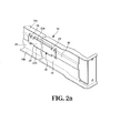
- the arrangement of the connection walls 28 as shown in Fig. 2a the connection walls 28 are arranged in vertical direction and connected between the intermediate portion 24 of the support member 18 and the side portion 16 of the bracket 10.
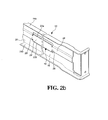
- the second arrangement of the connection walls 28 as shown in Fig. 2b the connection walls 28 are arranged in horizontal direction and connected between the intermediate portion 24 of the support member 18 and the rib 26 extended from the side portion 16 of the bracket 10.
- the arrangement of the connection walls 28 can also be shown in Fig. 2c which is a combination of the arrangements in Figs. 2a and 2b . Therefore, the first and second connection portions 22a, 22b are located away from the side portion 16 and a gap is defined between the connection portions 22a, 22b and the side portion 16.
- the rail 12 extends through the longitudinal path 20 of the bracket 10 and has a top wall 30a, a bottom wall 30b located corresponding to the top wall 30a, and a sidewall 32 connected to the top and the bottom walls 30a, 30b.
- the sidewall 32 has a reinforcement path 36 with a recessed surface 34.
- the reinforcement path 36 is located corresponding to the support member 18 of the bracket 10.
- the reinforcement path 36 extends along the longitudinal direction of the rail 12 and the rail 12 is reinforced by the curved cross section of the reinforcement path 36.
- the reinforcement path 36 has a first protrusion 38 and a second protrusion 40 located on the top and the bottom of the reinforcement path 36.
- the first protrusion 38 is connected to the sidewall 32 of the rail 12 and extends downward and into the reinforcement path 36.
- the second protrusion 40 is connected to the sidewall 32 of the rail 12 and extends upward and into the reinforcement path 36.
- the first and second protrusions 38, 40 extend from the sidewall 32 by way of pressing.
- the rail 12 is located in the longitudinal path 20 of the bracket 10.
- the top wall 30a of the rail 12 is engaged with the top portion 14a of the bracket 10, and the bottom wall 30b of the rail 12 is engaged with the bottom portion 14b of the bracket 10.
- the sidewall 32 of the rail 12 is located corresponding to the side portion 16 of the bracket 10.
- the support member 18 of the bracket 10 is located in the reinforcement path 36 of the rail 12, and the first and second connection portions 22a, 22b of the support member 18 respectively contact the first and second protrusions 38, 40. Therefore, the support member 18 movably extends through the reinforcement path 36. Accordingly, the connection of the bracket 10 and the rail 12, regardless the stationary or movable connection, the structure and anti-bent ability are reinforced.
- the second embodiment comprises a bracket 200 and a rail 202 engaged with the bracket 200.
- the bracket 200 has a side portion 204.
- the support member 206 has an intermediate portion 207 connected to the first and second connection portions 208a, 208b.
- the intermediate portion 207 is fixed to the side portion 204 of the bracket 200.
- the first connection portion 208a has a first bent section 210a which is located away from the side portion 204 of the bracket 200
- the second connection portion 208b of the support member 206 has a second bent section 210b which is located corresponding to the first bent section 210a.
- the third embodiment comprises a bracket 300 and a rail 302 engaged with the bracket 300.
- the bracket 300 has a side portion 304.
- the support member 306 has an intermediate portion 310 connected to the first and second connection portions 308a, 308b.
- the side portion 304 of the bracket 300 forms a rib 312 which is located corresponding to the intermediate portion 310 of the support member 306.
- the intermediate portion 310 is fixed to the rib 312 by way of rivets for example.
- the fourth embodiment comprises a bracket 400 and a rail 402 engaged with the bracket 400.
- the bracket 400 has a side portion 404.
- the support member 406 has an intermediate portion 410 connected to the first and second connection portions 408a, 408b.
- the side portion 404 of the bracket 400 has an opening 412 located corresponding to the intermediate portion 410 of the support member 406.
- the intermediate portion 410 of the support member 406 has a bent fixing section 414 which extends through the opening 412 and is connected to the side portion 404 of the bracket 400 by way of rivets for example.
- the fifth embodiment comprises a bracket 500 and a rail 502 engaged with the bracket 500.
- the bracket 500 has a side portion 504.
- the side portion 504 of the support member 500 has an opening 508.
- a first bent section 512a is connected between the first connection portion 510a of the support member 506 and the wall of the first end of the opening 508.
- a second bent section 512b is connected between the second connection portion 510b of the support member 506 and the wall of the second end of the opening 508.
- the second bent section 512b is located corresponding to the first bent section 512a.
- the sixth embodiment comprises a bracket 600 and a rail 602 engaged with the bracket 600.
- the bracket 600 has a side portion 604.
- the side portion 604 of the support member 600 has a first opening 608 located corresponding to the first connection portion 610a of the support member 606, a second opening 612 located corresponding to the second connection portion 610b of the support member 606.
- a first bent section 614a is connected between the first connection portion 610a and the wall of the first opening 608.
- a second bent section 614b is connected between the second connection portion 610b and the wall of the second opening 612.
- the first connection portion 610a extends upward from the first bent section 614a and the second connection portion 610b extends downward from the second bent section 614b.
- the seventh embodiment comprises a bracket 700 and a rail 702 engaged with the bracket 700.
- the bracket 700 has a side portion 704.
- the side portion 704 of the bracket 700 has a first opening 708 which is located corresponding to the first connection portion 710a of the support member 706, and a second opening 712 which is located corresponding to the second connection portion 710b of the support member 706.
- a first bent section 714a is connected between two respective walls of the first connection portion 710a and the first opening 708.
- a second bent section 714b is connected between two respective walls of the second connection portion 710b and the second opening 712.
- the first protrusion 716 is connected to the recessed surface 720 of the reinforcement path 718 and extends upward.
- the second protrusion 722 is connected to the recessed surface 720 of the reinforcement path 718 and extends downward.
- the first connection portion 710a extends downward from the first bent section 714a and the second connection portion 710b extends upward from the second bent section 714b.
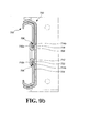
- the eighth embodiment comprises a bracket 800 and a rail 802 engaged with the bracket 800.
- the bracket 800 has a side portion 804.
- the side portion 804 of the bracket 800 has a first opening 808 located corresponding to the first connection portion 810a of the support member 806, and a second opening 812 located corresponding to the second connection portion 810b of the support member 806.
- a first bent section 814a is connected between the first connection portion 810a and the wall of the first opening 808.
- a second bent section 814b is connected between the second connection portion 810b and the wall of the second opening 812.
- a connection plate 824 is connected between the first and second protrusion 816, 822.
- connection plate 824 is fixed to the recessed surface 820 of the reinforcement path 818.
- the first protrusion 816 is located away from the recessed surface 820 of the reinforcement path 818 and extends upward.
- the second protrusion 822 is located away from the recessed surface 820 of the reinforcement path 818 and extends downward.
- the first connection portion 810a extends downward from the first bent section 814a and the second connection portion 810b extends upward from the second bent section 814b.
Landscapes
- Drawers Of Furniture (AREA)
Abstract
Description
- The present invention relates to a bracket and a slide assembly, and more particularly, to a structure that reinforces the connection strength between the bracket and the slide assembly.
-
U.S. Patent No. 6,726,164 to Baiza discloses a "Mounting bracket having a tapered plunger latch" which comprises a rail 52 and a bracket 54, wherein the bracket 54 has a body 98 and three slots 95 which extend along the longitudinal direction of the body 98 and are secured by extending fasteners 68 through the slots 95 and connected to the rail 52. However, the connection between the bracket 54 and the rail 52 is weak and cannot bear loads. -
U.S. Patent No. 6,854,816 to Milligan discloses a "Three member thin drawer slide" which comprises a bracket 151 slidably connected to an outer member 11 and an intermediate slide member 19 is connected to the outer member 11, and an inner slide member 27 connected to the intermediate slide member 19. The bracket 151 has two flanges 171, 173 which are in contact with the top and bottom of the outer member 11. However, when a load is applied to the inner and intermediate slide members 27, 19, the outer member 11 is also applied by the load, the bracket 151 and the outer member 11 are connected by the connection pin located in the slot at the intermediate portion of the outer member 11, the flanges 171, 173 of the bracket 151 are easily deformed by the pressure from the outer member 11. - Therefore, a reinforcement device for the slide assembly is needed, especially when the outer member and the bracket are made to be narrower.
- The present invention relates to a combination of bracket and slide assembly, and comprises a bracket having a top portion, a bottom portion located corresponding to the top portion, a side portion connected to the top and bottom portions, and a support member fixedly to the side portion. The top portion, the bottom portion and the side portion define a longitudinal path. The support member is located in the longitudinal path and has a first connection portion and a second connection portion, wherein the first and second connection portions are located away from the side portion. A rail extends through the longitudinal path of the bracket and has a top wall, a bottom wall located corresponding to the top wall, and a sidewall connected to the top and the bottom walls. The sidewall has a reinforcement path with a recessed surface. The reinforcement path extends along the longitudinal direction of the rail and located corresponding to the support member of the bracket. A first protrusion and a second protrusion are located on the top and the bottom of the reinforcement path. The top wall of the rail is engaged with the top portion of the bracket. The bottom wall of the rail is engaged with the bottom portion of the bracket. The sidewall of the rail is located corresponding to the side portion of the bracket. The first and second connection portions of the support member are respectively in contact with the first and second protrusions and located in the reinforcement path.
- Preferably, the first protrusion is connected to the sidewall of the rail and extends downward and into the reinforcement path. The second protrusion is connected to the sidewall of the rail and extends upward and into the reinforcement path.
- Preferably, the side portion of the bracket forms a rib which is located adjacent to the support member and the rib extends into the longitudinal path.
- Preferably, the support member has an intermediate portion connected to the first and second connection portions, and multiple connection walls connected between the intermediate portion of the support member and the side portion of the bracket.
- Preferably, the support member has an intermediate portion connected to the first and second connection portions. The intermediate portion is fixed to the side portion of the bracket. The first connection portion has a first bent section which is located away from the side portion of the bracket. The second connection portion of the support member has a second bent section which is located corresponding to the first bent section.
- Preferably, the support member has an intermediate portion connected to the first and second connection portions. The side portion of the bracket forms a rib which is located corresponding to the intermediate portion of the support member. The intermediate portion is fixed to the rib.
- Preferably, the support member has an intermediate portion connected to the first and second connection portions. The side portion of the bracket has an opening located corresponding to the intermediate portion of the support member. The intermediate portion of the support member has a bent fixing section which extends through the opening and is connected to the side portion of the bracket.
- Preferably, the side portion of the support member has an opening. A first bent section is connected between the first connection portion of the support member and a wall of a first end of the opening. A second bent section is connected between the second connection portion and a wall of a second end of the opening. The second bent section is located corresponding to the first bent section.
- Preferably, the side portion of the support member has a first opening located corresponding to the first connection portion of the support member. A second opening is located corresponding to the second connection portion of the support member. A first bent section is connected between the first connection portion and a wall of the first opening. A second bent section is connected between the second connection portion and a wall of the second opening. The first connection portion extends upward from the first bent section and the second connection portion extends downward from the second bent section.
- Preferably, the first protrusion is connected to the recessed surface of the reinforcement path and extends upward. The second protrusion is connected to the recessed surface of the reinforcement path and extends downward. The side portion of the bracket has a first opening which is located corresponding to the first connection portion of the support member, and a second opening which is located corresponding to the second connection portion of the support member. A first bent section is connected between two respective walls of the first connection portion and the first opening. A second bent section is connected between two respective walls of the second connection portion and the second opening. The first connection portion extends downward from the first bent section and the second connection portion extends upward from the second bent section.
- Preferably, a connection plate is connected between the first and second protrusion. The connection plate is fixed to the recessed surface of the reinforcement path. The first protrusion is located away from the recessed surface of the reinforcement path and extends upward. The second protrusion is located away from the recessed surface of the reinforcement path and extends downward. The side portion of the bracket has a first opening located corresponding to the first connection portion of the support member, and a second opening located corresponding to the second connection portion of the support member. A first bent section is connected between the first connection portion and a wall of the first opening. A second bent section is connected between the second connection portion and a wall of the second opening. The first connection portion extends downward from the first bent section and the second connection portion extends upward from the second bent section.
- The primary object of the present invention is to provide a combination of a bracket and a slide assembly, wherein the structure of the bracket is reinforced regardless of the movement between the bracket and the rail.
- The present invention will become more obvious from the following description when taken in connection with the accompanying drawings which show, for purposes of illustration only, a preferred embodiment in accordance with the present invention.
-
-
Fig. 1 is an exploded view to show the bracket and the rail of the present invention; -
Fig. 2a shows the first connection of the first embodiment between the bracket and the support member; -
Fig. 2b shows the second connection of the first embodiment between the bracket and the support member; -
Fig. 2c shows the third connection of the first embodiment between the bracket and the support member; -
Fig. 3 is a cross sectional view to show the bracket and the rail of the present invention; -
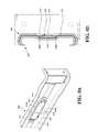
Fig. 4a shows the connection of the second embodiment between the bracket and the support member; -
Fig. 4b shows the cross sectional view of the second embodiment between the bracket and the rail; -
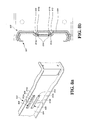
Fig. 5a shows the connection of the third embodiment between the bracket and the support member; -
Fig. 5b shows the cross sectional view of the third embodiment between the bracket and the rail; -
Fig. 6a shows the connection of the fourth embodiment between the bracket and the support member; -
Fig. 6b shows the cross sectional view of the fourth embodiment between the bracket and the rail; -
Fig. 7a shows the connection of the fifth embodiment between the bracket and the support member; -
Fig. 7b shows the cross sectional view of the fifth embodiment between the bracket and the rail; -
Fig. 8a shows the connection view of the sixth embodiment between the bracket and the support member; -
Fig. 8b shows the cross sectional view of the sixth embodiment between the bracket and the support member; -
Fig. 9a shows the connection of the seventh embodiment between the bracket and the rail; -
Fig. 9b shows the cross sectional view of the seventh embodiment between the bracket and the rail; -
Fig. 10a shows the connection of the eighth embodiment between the bracket and the rail, and -
Fig. 10b shows the cross sectional view of the seventh embodiment between the bracket and the rail. - Referring to
Fig. 1 , the bracket and the slide assembly of the first embodiment of the present invention comprises abracket 10 and arail 12, wherein thebracket 10 has atop portion 14a, abottom portion 14b located corresponding to thetop portion 14a, aside portion 16 connected to the top andbottom portions support member 18 fixedly to theside portion 16. Thetop portion 14a, thebottom portion 14b and theside portion 16 define alongitudinal path 20. Thesupport member 18 is located in thelongitudinal path 20 by a means and preferably, by way of pressing. Thesupport member 18 has afirst connection portion 22a and asecond connection portion 22b. Thesupport member 18 has anintermediate portion 24 connected to the first andsecond connection portions side portion 16 of thebracket 10 forms arib 26 which is located adjacent to thesupport member 18 and therib 26 extends into thelongitudinal path 20.Multiple connection walls 28 are connected between theintermediate portion 24 of thesupport member 18 and the side portion 16 (or the rib 26) of thebracket 10. The arrangement of theconnection walls 28 as shown inFig. 2a , theconnection walls 28 are arranged in vertical direction and connected between theintermediate portion 24 of thesupport member 18 and theside portion 16 of thebracket 10. The second arrangement of theconnection walls 28 as shown inFig. 2b , theconnection walls 28 are arranged in horizontal direction and connected between theintermediate portion 24 of thesupport member 18 and therib 26 extended from theside portion 16 of thebracket 10. The arrangement of theconnection walls 28 can also be shown inFig. 2c which is a combination of the arrangements inFigs. 2a and2b . Therefore, the first andsecond connection portions side portion 16 and a gap is defined between theconnection portions side portion 16. - The
rail 12 extends through thelongitudinal path 20 of thebracket 10 and has atop wall 30a, abottom wall 30b located corresponding to thetop wall 30a, and asidewall 32 connected to the top and thebottom walls sidewall 32 has areinforcement path 36 with a recessedsurface 34. Thereinforcement path 36 is located corresponding to thesupport member 18 of thebracket 10. Thereinforcement path 36 extends along the longitudinal direction of therail 12 and therail 12 is reinforced by the curved cross section of thereinforcement path 36. Thereinforcement path 36 has afirst protrusion 38 and asecond protrusion 40 located on the top and the bottom of thereinforcement path 36. In detail, thefirst protrusion 38 is connected to thesidewall 32 of therail 12 and extends downward and into thereinforcement path 36. Thesecond protrusion 40 is connected to thesidewall 32 of therail 12 and extends upward and into thereinforcement path 36. Preferably, there are multiple first andsecond protrusions reinforcement path 36. The first andsecond protrusions sidewall 32 by way of pressing. - As shown in
Fig. 3 , therail 12 is located in thelongitudinal path 20 of thebracket 10. Thetop wall 30a of therail 12 is engaged with thetop portion 14a of thebracket 10, and thebottom wall 30b of therail 12 is engaged with thebottom portion 14b of thebracket 10. Thesidewall 32 of therail 12 is located corresponding to theside portion 16 of thebracket 10. Thesupport member 18 of thebracket 10 is located in thereinforcement path 36 of therail 12, and the first andsecond connection portions support member 18 respectively contact the first andsecond protrusions support member 18 movably extends through thereinforcement path 36. Accordingly, the connection of thebracket 10 and therail 12, regardless the stationary or movable connection, the structure and anti-bent ability are reinforced. - As shown in
Figs. 4a and 4b , the second embodiment comprises abracket 200 and arail 202 engaged with thebracket 200. Thebracket 200 has aside portion 204. Thesupport member 206 has anintermediate portion 207 connected to the first andsecond connection portions intermediate portion 207 is fixed to theside portion 204 of thebracket 200. Thefirst connection portion 208a has a firstbent section 210a which is located away from theside portion 204 of thebracket 200, thesecond connection portion 208b of thesupport member 206 has a secondbent section 210b which is located corresponding to the firstbent section 210a. - As shown in
Figs. 5a and 5b , the third embodiment comprises abracket 300 and arail 302 engaged with thebracket 300. Thebracket 300 has aside portion 304. Thesupport member 306 has anintermediate portion 310 connected to the first andsecond connection portions side portion 304 of thebracket 300 forms arib 312 which is located corresponding to theintermediate portion 310 of thesupport member 306. Theintermediate portion 310 is fixed to therib 312 by way of rivets for example. - As shown in
Figs. 6a and 6b , the fourth embodiment comprises abracket 400 and arail 402 engaged with thebracket 400. Thebracket 400 has aside portion 404. Thesupport member 406 has anintermediate portion 410 connected to the first andsecond connection portions side portion 404 of thebracket 400 has anopening 412 located corresponding to theintermediate portion 410 of thesupport member 406. Theintermediate portion 410 of thesupport member 406 has abent fixing section 414 which extends through theopening 412 and is connected to theside portion 404 of thebracket 400 by way of rivets for example. - As shown in
Figs. 7a and 7b , the fifth embodiment comprises abracket 500 and arail 502 engaged with thebracket 500. Thebracket 500 has aside portion 504. Theside portion 504 of thesupport member 500 has anopening 508. A firstbent section 512a is connected between thefirst connection portion 510a of thesupport member 506 and the wall of the first end of theopening 508. A secondbent section 512b is connected between thesecond connection portion 510b of thesupport member 506 and the wall of the second end of theopening 508. The secondbent section 512b is located corresponding to the firstbent section 512a. - As shown in
Figs. 8a and 8b , the sixth embodiment comprises abracket 600 and arail 602 engaged with thebracket 600. Thebracket 600 has aside portion 604. Theside portion 604 of thesupport member 600 has afirst opening 608 located corresponding to thefirst connection portion 610a of thesupport member 606, asecond opening 612 located corresponding to thesecond connection portion 610b of thesupport member 606. A firstbent section 614a is connected between thefirst connection portion 610a and the wall of thefirst opening 608. A secondbent section 614b is connected between thesecond connection portion 610b and the wall of thesecond opening 612. Thefirst connection portion 610a extends upward from the firstbent section 614a and thesecond connection portion 610b extends downward from the secondbent section 614b. - As shown in
Figs. 9a and9b , the seventh embodiment comprises abracket 700 and arail 702 engaged with thebracket 700. Thebracket 700 has aside portion 704. Theside portion 704 of thebracket 700 has afirst opening 708 which is located corresponding to thefirst connection portion 710a of thesupport member 706, and asecond opening 712 which is located corresponding to thesecond connection portion 710b of thesupport member 706. A firstbent section 714a is connected between two respective walls of thefirst connection portion 710a and thefirst opening 708. A secondbent section 714b is connected between two respective walls of thesecond connection portion 710b and thesecond opening 712. Thefirst protrusion 716 is connected to the recessed surface 720 of thereinforcement path 718 and extends upward. Thesecond protrusion 722 is connected to the recessed surface 720 of thereinforcement path 718 and extends downward. Thefirst connection portion 710a extends downward from the firstbent section 714a and thesecond connection portion 710b extends upward from the secondbent section 714b. - As shown in
Figs. 10a and10b , the eighth embodiment comprises abracket 800 and arail 802 engaged with thebracket 800. Thebracket 800 has aside portion 804. Theside portion 804 of thebracket 800 has afirst opening 808 located corresponding to thefirst connection portion 810a of thesupport member 806, and asecond opening 812 located corresponding to thesecond connection portion 810b of thesupport member 806. A firstbent section 814a is connected between thefirst connection portion 810a and the wall of thefirst opening 808. A secondbent section 814b is connected between thesecond connection portion 810b and the wall of thesecond opening 812. Aconnection plate 824 is connected between the first andsecond protrusion connection plate 824 is fixed to the recessedsurface 820 of thereinforcement path 818. Thefirst protrusion 816 is located away from the recessedsurface 820 of thereinforcement path 818 and extends upward. Thesecond protrusion 822 is located away from the recessedsurface 820 of thereinforcement path 818 and extends downward. Thefirst connection portion 810a extends downward from the firstbent section 814a and thesecond connection portion 810b extends upward from the secondbent section 814b. By the arrangement, thebracket 800 and therail 802 can be movably connected to thereinforcement path 818 by thesupport member 806. - While we have shown and described the embodiment in accordance with the present invention, it should be clear to those skilled in the art that further embodiments may be made without departing from the scope of the present invention.
Claims (12)
- A combination of bracket and slide assembly, comprising:a bracket (10) having a top portion (14a), a bottom portion (14b) located corresponding to the top portion (14a), a side portion (16) connected to the top and bottom portions (14a, 14b), and a support member (18) fixedly to the side portion (16), the top portion (14a), the bottom portion (14b) and the side portion (16) defining a longitudinal path (20), the support member (18) located in the longitudinal path (20) and having a first connection portion (22a) and a second connection portion (22b), the first and second connection portions (22a, 22b) located away from the side portion (16); anda rail (12) extending through the longitudinal path (20) of the bracket (10) and having a top wall (30a), a bottom wall (30b) located corresponding to the top wall (30a), and a sidewall (32) connected to the top and the bottom walls (30a, 30b), the sidewall (32) having a reinforcement path (36) with a recessed surface (34), the reinforcement path (36) extending along a longitudinal direction of the rail (12) and located corresponding to the support member (18) of the bracket (10), a first protrusion (38) and a second protrusion (40) located on a top and a bottom of the reinforcement path (36);wherein the top wall (30a) of the rail (12) is engaged with the top portion (14a) of the bracket (10), the bottom wall (30b) of the rail (12) is engaged with the bottom portion (14b) of the bracket (10), the sidewall (32) of the rail (12) is located corresponding to the side portion (16) of the bracket (10), the first and second connection portions (22a, 22b) of the support member (18) respectively contact the first and second protrusions (38, 40) and are located in the reinforcement path (36).
- The combination as claimed in claim 1, wherein the first protrusion (38) is connected to the sidewall (32) of the rail (12) and extends downward and into the reinforcement path (36), the second protrusion (40) is connected to the sidewall (32) of the rail (12) and extends upward and into the reinforcement path (36).
- The combination as claimed in claim 1, wherein the support member (18) has an intermediate portion (24) connected to the first and second connection portions (22a, 22b), and multiple connection walls (28) connected between the intermediate portion (24) of the support member (18) and the side portion (16) of the bracket (10).
- The combination as claimed in claim 1, wherein the side portion (16) of the bracket (10) forms a rib (26) which is located adjacent to the support member (18) and the rib (26) extends into the longitudinal path (20).
- The combination as claimed in claim 4, wherein the support member (18) has an intermediate portion (24) connected to the first and second connection portions (22a, 22b), and multiple connection walls (28) connected between the intermediate portion (24) of the support member (18) and the side portion (16) of the bracket (10).
- The combination as claimed in claim 1, wherein the support member (206) has an intermediate portion (207) connected to the first and second connection portions (208a, 208b), the intermediate portion (207) is fixed to the side portion (204) of the bracket (200), the first connection portion (208a) has a first bent section (210a) which is located away from the side portion (204) of the bracket (200), the second connection portion (208b) of the support member (206) has a second bent section (210b) which is located corresponding to the first bent section (210a).
- The combination as claimed in claim 1, wherein the support member (306) has an intermediate portion (310) connected to the first and second connection portions (308a, 308b), the side portion (304) of the bracket (300) forms a rib (312) which is located corresponding to the intermediate portion (310) of the support member (306), the intermediate portion (310) is fixed to the rib (312).
- The combination as claimed in claim 1, wherein the support member (406) has an intermediate portion (410) connected to the first and second connection portions (408a, 408b), the side portion (404) of the bracket (400) has an opening (412) located corresponding to the intermediate portion (410) of the support member (406), the intermediate portion (410) of the support member (406) has a bent fixing section (414) which extends through the opening (412) and is connected to the side portion (404) of the bracket (400).
- The combination as claimed in claim 1, wherein the side portion (504) of the support member (500) has an opening (508), a first bent section (512a) is connected between the first connection portion (510a) of the support member (506) and a wall of a first end of the opening (508), a second bent section (512b) is connected between the second connection portion (510b) and a wall of a second end of the opening (508), the second bent section (512b) is located corresponding to the first bent section (512a).
- The combination as claimed in claim 1, wherein the side portion (604) of the support member (600) has a first opening (608) located corresponding to the first connection portion (610a) of the support member (606), a second opening (612) located corresponding to the second connection portion (610b) of the support member (606), a first bent section (614a) is connected between the first connection portion (610a) and a wall of the first opening (608), a second bent section (614b) is connected between the second connection portion (610b) and a wall of the second opening (612), the first connection portion (610a) extends upward from the first bent section (614a) and the second connection portion (610b) extends downward from the second bent section (614b).
- The combination as claimed in claim 1, wherein the first protrusion (716) is connected to the recessed surface (720) of the reinforcement path (718) and extends upward, the second protrusion (722) is connected to the recessed surface (720) of the reinforcement path (718) and extends downward, the side portion (704) of the bracket (700) has a first opening (708) which is located corresponding to the first connection portion (710a) of the support member (706) and a second opening (712) which is located corresponding to the second connection portion (710b) of the support member (706), a first bent section (714a) is connected between two respective walls of the first connection portion (710a) and the first opening (708), a second bent section (714b) is connected between two respective walls of the second connection portion (710b) and the second opening (712), the first connection portion (710a) extends downward from the first bent section (714a) and the second connection portion (710b) extends upward from the second bent section (714b).
- The combination as claimed in claim 1, wherein a connection plate (824) is connected between the first and second protrusion (816, 822), the connection plate (824) is fixed to the recessed surface (820) of the reinforcement path (818), the first protrusion (816) is located away from the recessed surface (820) of the reinforcement path (818) and extends upward, the second protrusion (822) is located away from the recessed surface (820) of the reinforcement path (818) and extends downward, the side portion (804) of the bracket (800) has a first opening (808) located corresponding to the first connection portion (810a) of the support member (806), and a second opening (812) located corresponding to the second connection portion (810b) of the support member (806), a first bent section (814a) is connected between the first connection portion (810a) and a wall of the first opening (808), a second bent section (814b) is connected between the second connection portion (810b) and a wall of the second opening (812), the first connection portion (810a) extends downward from the first bent section (814a) and the second connection portion (810b) extends upward from the second bent section (814b).
Applications Claiming Priority (1)
| Application Number | Priority Date | Filing Date | Title |
|---|---|---|---|
| TW99139844A TWI468097B (en) | 2010-11-18 | 2010-11-18 | Bracket and slide assembly |
Publications (2)
| Publication Number | Publication Date |
|---|---|
| EP2454970A1 true EP2454970A1 (en) | 2012-05-23 |
| EP2454970B1 EP2454970B1 (en) | 2013-08-28 |
Family
ID=44677723
Family Applications (1)
| Application Number | Title | Priority Date | Filing Date |
|---|---|---|---|
| EP11181770.6A Active EP2454970B1 (en) | 2010-11-18 | 2011-09-19 | Combination of bracket and slide assembly |
Country Status (4)
| Country | Link |
|---|---|
| US (1) | US8733866B2 (en) |
| EP (1) | EP2454970B1 (en) |
| JP (1) | JP3171621U (en) |
| TW (1) | TWI468097B (en) |
Cited By (1)
| Publication number | Priority date | Publication date | Assignee | Title |
|---|---|---|---|---|
| EP3189750A1 (en) * | 2016-01-06 | 2017-07-12 | King Slide Works Co., Ltd. | Slide rail assembly |
Families Citing this family (15)
| Publication number | Priority date | Publication date | Assignee | Title |
|---|---|---|---|---|
| CN105682411B (en) * | 2014-11-20 | 2018-08-03 | 川湖科技股份有限公司 | Slide rail assembly and its bracket device |
| CN105722367B (en) * | 2014-12-02 | 2018-08-03 | 川湖科技股份有限公司 | Sliding rail assembly |
| CN105992485B (en) * | 2015-02-06 | 2019-02-01 | 川湖科技股份有限公司 | Sliding rail assembly |
| US9861197B2 (en) * | 2015-02-13 | 2018-01-09 | King Slide Works Co., Ltd. | Slide rail assembly |
| TWI561153B (en) * | 2015-10-06 | 2016-12-01 | King Slide Works Co Ltd | Slide rail assembly with bracket |
| CN107007050B (en) * | 2016-01-11 | 2020-12-01 | 川湖科技股份有限公司 | Slide rail assembly |
| TWI610639B (en) * | 2016-11-22 | 2018-01-11 | 川湖科技股份有限公司 | Slide rail assembly |
| CN108235643B (en) * | 2016-12-21 | 2020-06-05 | 伊姆西Ip控股有限责任公司 | Guide rail for cabinet, cabinet and cabinet |
| CN108958386B (en) * | 2017-05-23 | 2021-10-01 | 鸿富锦精密电子(天津)有限公司 | Sliding rail bracket structure |
| NL2022397B1 (en) * | 2019-01-14 | 2020-08-14 | Walraven Holding Bv J Van | Profiled section element with stepped sidewall |
| TWI726418B (en) * | 2019-09-12 | 2021-05-01 | 川湖科技股份有限公司 | Telescopic mechanism |
| TWD214175S (en) | 2020-12-09 | 2021-09-21 | 南俊國際股份有限公司 | bracket |
| TWI739718B (en) * | 2021-03-10 | 2021-09-11 | 川湖科技股份有限公司 | Slide rail mechanism and slide rail kit thereof |
| USD1061246S1 (en) * | 2022-03-15 | 2025-02-11 | Schoeller Allibert Gmbh | Spacer for stacking multiple containers |
| DE102022109787A1 (en) | 2022-04-22 | 2023-10-26 | Schock Metallwerk Gmbh. | Excerpt guide |
Citations (6)
| Publication number | Priority date | Publication date | Assignee | Title |
|---|---|---|---|---|
| US3744869A (en) * | 1971-07-06 | 1973-07-10 | Amerock Corp | Drawer with guide tracks |
| US6726164B1 (en) | 2001-04-26 | 2004-04-27 | Central Industrial Supply, Company, Inc. | Mounting bracket having a tapered plunger latch |
| US6854816B2 (en) | 2001-10-12 | 2005-02-15 | Accuride International Inc. | Three member thin drawer slide |
| DE202009007022U1 (en) * | 2008-05-16 | 2009-09-03 | King Slide Works Co., Ltd., Lu-Chu Hsiang | Holder for a pull-out rail |
| US20100046863A1 (en) * | 2008-08-20 | 2010-02-25 | Chi-Tsun Cheng | Drawable track assembly |
| WO2010148645A1 (en) * | 2009-06-25 | 2010-12-29 | 宁波邦达实业有限公司 | Detachable drawer slide rail |
Family Cites Families (12)
| Publication number | Priority date | Publication date | Assignee | Title |
|---|---|---|---|---|
| US6230903B1 (en) * | 1999-10-27 | 2001-05-15 | Hewlett-Packard Company | Snap-on rack slide mounting system |
| US6681942B2 (en) * | 1999-10-27 | 2004-01-27 | Hewlett-Packard Development Company | Rack mount assembly |
| US20020074915A1 (en) * | 2000-12-15 | 2002-06-20 | Shoei-Yuan Shih | Slideout support for server cabinet |
| DE10156931C2 (en) * | 2001-11-19 | 2003-10-30 | Rittal Gmbh & Co Kg | Universal installation kit for a device that can be built into a frame |
| US6615992B1 (en) * | 2002-03-11 | 2003-09-09 | Hewlett-Packard Development Company L.P. | Adjustable rackmount assembly |
| US20040217073A1 (en) * | 2003-05-01 | 2004-11-04 | Dobler Karl J. | System and method for utilizing a tool-less rail in a rack |
| US7350884B2 (en) | 2004-03-29 | 2008-04-01 | Emc Corporation | Tray with integrated rail guides for facilitating installation of equipment units into a cabinet rack |
| JP4175325B2 (en) * | 2005-01-18 | 2008-11-05 | 日本電気株式会社 | rack |
| TWM277202U (en) * | 2005-04-19 | 2005-10-01 | Speed Tech Corp | Light sliding mechanism |
| US20080036347A1 (en) * | 2006-08-09 | 2008-02-14 | Super Micro Computer, Inc. | Rail device for extracting computer equipment |
| TWM374793U (en) * | 2008-05-16 | 2010-03-01 | zhen-hong Zhuang | Multi-sectioned slide rail structure |
| US8132874B2 (en) * | 2009-05-08 | 2012-03-13 | Oracle America, Inc. | Server chassis rack rail with self-aligning, magnetic guide assembly for positioning servers in storage rack |
-
2010
- 2010-11-18 TW TW99139844A patent/TWI468097B/en active
-
2011
- 2011-08-29 JP JP2011005031U patent/JP3171621U/en not_active Expired - Lifetime
- 2011-08-30 US US13/220,986 patent/US8733866B2/en active Active
- 2011-09-19 EP EP11181770.6A patent/EP2454970B1/en active Active
Patent Citations (6)
| Publication number | Priority date | Publication date | Assignee | Title |
|---|---|---|---|---|
| US3744869A (en) * | 1971-07-06 | 1973-07-10 | Amerock Corp | Drawer with guide tracks |
| US6726164B1 (en) | 2001-04-26 | 2004-04-27 | Central Industrial Supply, Company, Inc. | Mounting bracket having a tapered plunger latch |
| US6854816B2 (en) | 2001-10-12 | 2005-02-15 | Accuride International Inc. | Three member thin drawer slide |
| DE202009007022U1 (en) * | 2008-05-16 | 2009-09-03 | King Slide Works Co., Ltd., Lu-Chu Hsiang | Holder for a pull-out rail |
| US20100046863A1 (en) * | 2008-08-20 | 2010-02-25 | Chi-Tsun Cheng | Drawable track assembly |
| WO2010148645A1 (en) * | 2009-06-25 | 2010-12-29 | 宁波邦达实业有限公司 | Detachable drawer slide rail |
Cited By (1)
| Publication number | Priority date | Publication date | Assignee | Title |
|---|---|---|---|---|
| EP3189750A1 (en) * | 2016-01-06 | 2017-07-12 | King Slide Works Co., Ltd. | Slide rail assembly |
Also Published As
| Publication number | Publication date |
|---|---|
| TW201223411A (en) | 2012-06-01 |
| EP2454970B1 (en) | 2013-08-28 |
| US8733866B2 (en) | 2014-05-27 |
| JP3171621U (en) | 2011-11-10 |
| US20120128278A1 (en) | 2012-05-24 |
| TWI468097B (en) | 2015-01-01 |
Similar Documents
| Publication | Publication Date | Title |
|---|---|---|
| EP2454970B1 (en) | Combination of bracket and slide assembly | |
| US8721012B2 (en) | Reinforcement and adjustment device for slide assembly | |
| EP2438835A1 (en) | Reinforcement device for slide assembly | |
| US7744177B2 (en) | Mounting apparatus for slide rail | |
| EP2757274A1 (en) | Fastener | |
| JP2013519852A (en) | Fixing device | |
| US9371649B2 (en) | Support metal structure of a false ceiling | |
| JP2014505845A (en) | Fixing device | |
| CN206213617U (en) | Drawer wall element and furniture with the drawer wall element | |
| US20170110268A1 (en) | Input device, electronic equipment, and method of manufacturing the input device | |
| CN108916172A (en) | A kind of buckle structure and air conditioner | |
| CN104414487A (en) | Drawer assembly and oven with drawer assembly | |
| CN101422799A (en) | The device that is used for the connection with holes of metallic plate | |
| CN102525149A (en) | Bracket and sliding rail assembly | |
| CN105848524B (en) | Furniture drawer and drawer wall elements for drawer | |
| CN101194801A (en) | Kitchen unit with handle | |
| CN203974491U (en) | For reinforced support, car door and the vehicle of car door | |
| US20090235801A1 (en) | Base For A Paper Punch And A Paper Punch With Such A Base | |
| KR200408932Y1 (en) | Furniture reinforcement assembly member | |
| US11821450B2 (en) | Rivet | |
| KR101304781B1 (en) | a shelf wall prop reinforcement and angle have control measure | |
| CN204572666U (en) | Combined fastener | |
| EP2664256B1 (en) | Reinforced metallic shelf for modular shelves structure | |
| EP2901891B1 (en) | Slide assembly | |
| CN201422763Y (en) | Connecting structure for panhandle and pan body |
Legal Events
| Date | Code | Title | Description |
|---|---|---|---|
| PUAI | Public reference made under article 153(3) epc to a published international application that has entered the european phase |
Free format text: ORIGINAL CODE: 0009012 |
|
| AK | Designated contracting states |
Kind code of ref document: A1 Designated state(s): AL AT BE BG CH CY CZ DE DK EE ES FI FR GB GR HR HU IE IS IT LI LT LU LV MC MK MT NL NO PL PT RO RS SE SI SK SM TR |
|
| AX | Request for extension of the european patent |
Extension state: BA ME |
|
| 17P | Request for examination filed |
Effective date: 20121123 |
|
| GRAJ | Information related to disapproval of communication of intention to grant by the applicant or resumption of examination proceedings by the epo deleted |
Free format text: ORIGINAL CODE: EPIDOSDIGR1 |
|
| GRAP | Despatch of communication of intention to grant a patent |
Free format text: ORIGINAL CODE: EPIDOSNIGR1 |
|
| RIC1 | Information provided on ipc code assigned before grant |
Ipc: A47B 88/00 20060101ALI20130228BHEP Ipc: A47B 88/04 20060101AFI20130228BHEP |
|
| RIN1 | Information on inventor provided before grant (corrected) |
Inventor name: CHEN, KEN-CHING Inventor name: HUANG, CHIEN-LI Inventor name: WANG, CHUN-CHIANG |
|
| GRAS | Grant fee paid |
Free format text: ORIGINAL CODE: EPIDOSNIGR3 |
|
| GRAA | (expected) grant |
Free format text: ORIGINAL CODE: 0009210 |
|
| AK | Designated contracting states |
Kind code of ref document: B1 Designated state(s): AL AT BE BG CH CY CZ DE DK EE ES FI FR GB GR HR HU IE IS IT LI LT LU LV MC MK MT NL NO PL PT RO RS SE SI SK SM TR |
|
| REG | Reference to a national code |
Ref country code: GB Ref legal event code: FG4D |
|
| REG | Reference to a national code |
Ref country code: CH Ref legal event code: EP |
|
| REG | Reference to a national code |
Ref country code: AT Ref legal event code: REF Ref document number: 628808 Country of ref document: AT Kind code of ref document: T Effective date: 20130915 |
|
| REG | Reference to a national code |
Ref country code: IE Ref legal event code: FG4D |
|
| REG | Reference to a national code |
Ref country code: DE Ref legal event code: R096 Ref document number: 602011002817 Country of ref document: DE Effective date: 20131024 |
|
| REG | Reference to a national code |
Ref country code: NL Ref legal event code: T3 |
|
| REG | Reference to a national code |
Ref country code: AT Ref legal event code: MK05 Ref document number: 628808 Country of ref document: AT Kind code of ref document: T Effective date: 20130828 |
|
| REG | Reference to a national code |
Ref country code: LT Ref legal event code: MG4D |
|
| PG25 | Lapsed in a contracting state [announced via postgrant information from national office to epo] |
Ref country code: AT Free format text: LAPSE BECAUSE OF FAILURE TO SUBMIT A TRANSLATION OF THE DESCRIPTION OR TO PAY THE FEE WITHIN THE PRESCRIBED TIME-LIMIT Effective date: 20130828 Ref country code: IS Free format text: LAPSE BECAUSE OF FAILURE TO SUBMIT A TRANSLATION OF THE DESCRIPTION OR TO PAY THE FEE WITHIN THE PRESCRIBED TIME-LIMIT Effective date: 20131228 Ref country code: SE Free format text: LAPSE BECAUSE OF FAILURE TO SUBMIT A TRANSLATION OF THE DESCRIPTION OR TO PAY THE FEE WITHIN THE PRESCRIBED TIME-LIMIT Effective date: 20130828 Ref country code: PT Free format text: LAPSE BECAUSE OF FAILURE TO SUBMIT A TRANSLATION OF THE DESCRIPTION OR TO PAY THE FEE WITHIN THE PRESCRIBED TIME-LIMIT Effective date: 20131230 Ref country code: HR Free format text: LAPSE BECAUSE OF FAILURE TO SUBMIT A TRANSLATION OF THE DESCRIPTION OR TO PAY THE FEE WITHIN THE PRESCRIBED TIME-LIMIT Effective date: 20130828 Ref country code: NO Free format text: LAPSE BECAUSE OF FAILURE TO SUBMIT A TRANSLATION OF THE DESCRIPTION OR TO PAY THE FEE WITHIN THE PRESCRIBED TIME-LIMIT Effective date: 20131128 Ref country code: CY Free format text: LAPSE BECAUSE OF FAILURE TO SUBMIT A TRANSLATION OF THE DESCRIPTION OR TO PAY THE FEE WITHIN THE PRESCRIBED TIME-LIMIT Effective date: 20130828 Ref country code: LT Free format text: LAPSE BECAUSE OF FAILURE TO SUBMIT A TRANSLATION OF THE DESCRIPTION OR TO PAY THE FEE WITHIN THE PRESCRIBED TIME-LIMIT Effective date: 20130828 |
|
| PG25 | Lapsed in a contracting state [announced via postgrant information from national office to epo] |
Ref country code: FI Free format text: LAPSE BECAUSE OF FAILURE TO SUBMIT A TRANSLATION OF THE DESCRIPTION OR TO PAY THE FEE WITHIN THE PRESCRIBED TIME-LIMIT Effective date: 20130828 Ref country code: BE Free format text: LAPSE BECAUSE OF FAILURE TO SUBMIT A TRANSLATION OF THE DESCRIPTION OR TO PAY THE FEE WITHIN THE PRESCRIBED TIME-LIMIT Effective date: 20130828 Ref country code: PL Free format text: LAPSE BECAUSE OF FAILURE TO SUBMIT A TRANSLATION OF THE DESCRIPTION OR TO PAY THE FEE WITHIN THE PRESCRIBED TIME-LIMIT Effective date: 20130828 Ref country code: SI Free format text: LAPSE BECAUSE OF FAILURE TO SUBMIT A TRANSLATION OF THE DESCRIPTION OR TO PAY THE FEE WITHIN THE PRESCRIBED TIME-LIMIT Effective date: 20130828 Ref country code: LV Free format text: LAPSE BECAUSE OF FAILURE TO SUBMIT A TRANSLATION OF THE DESCRIPTION OR TO PAY THE FEE WITHIN THE PRESCRIBED TIME-LIMIT Effective date: 20130828 |
|
| PG25 | Lapsed in a contracting state [announced via postgrant information from national office to epo] |
Ref country code: DK Free format text: LAPSE BECAUSE OF FAILURE TO SUBMIT A TRANSLATION OF THE DESCRIPTION OR TO PAY THE FEE WITHIN THE PRESCRIBED TIME-LIMIT Effective date: 20130828 Ref country code: RO Free format text: LAPSE BECAUSE OF FAILURE TO SUBMIT A TRANSLATION OF THE DESCRIPTION OR TO PAY THE FEE WITHIN THE PRESCRIBED TIME-LIMIT Effective date: 20130828 Ref country code: SK Free format text: LAPSE BECAUSE OF FAILURE TO SUBMIT A TRANSLATION OF THE DESCRIPTION OR TO PAY THE FEE WITHIN THE PRESCRIBED TIME-LIMIT Effective date: 20130828 Ref country code: EE Free format text: LAPSE BECAUSE OF FAILURE TO SUBMIT A TRANSLATION OF THE DESCRIPTION OR TO PAY THE FEE WITHIN THE PRESCRIBED TIME-LIMIT Effective date: 20130828 |
|
| PG25 | Lapsed in a contracting state [announced via postgrant information from national office to epo] |
Ref country code: ES Free format text: LAPSE BECAUSE OF FAILURE TO SUBMIT A TRANSLATION OF THE DESCRIPTION OR TO PAY THE FEE WITHIN THE PRESCRIBED TIME-LIMIT Effective date: 20130828 Ref country code: MC Free format text: LAPSE BECAUSE OF FAILURE TO SUBMIT A TRANSLATION OF THE DESCRIPTION OR TO PAY THE FEE WITHIN THE PRESCRIBED TIME-LIMIT Effective date: 20130828 Ref country code: IT Free format text: LAPSE BECAUSE OF FAILURE TO SUBMIT A TRANSLATION OF THE DESCRIPTION OR TO PAY THE FEE WITHIN THE PRESCRIBED TIME-LIMIT Effective date: 20130828 |
|
| REG | Reference to a national code |
Ref country code: DE Ref legal event code: R097 Ref document number: 602011002817 Country of ref document: DE |
|
| PLBE | No opposition filed within time limit |
Free format text: ORIGINAL CODE: 0009261 |
|
| STAA | Information on the status of an ep patent application or granted ep patent |
Free format text: STATUS: NO OPPOSITION FILED WITHIN TIME LIMIT |
|
| 26N | No opposition filed |
Effective date: 20140530 |
|
| REG | Reference to a national code |
Ref country code: FR Ref legal event code: ST Effective date: 20140709 |
|
| REG | Reference to a national code |
Ref country code: DE Ref legal event code: R097 Ref document number: 602011002817 Country of ref document: DE Effective date: 20140530 |
|
| PG25 | Lapsed in a contracting state [announced via postgrant information from national office to epo] |
Ref country code: FR Free format text: LAPSE BECAUSE OF NON-PAYMENT OF DUE FEES Effective date: 20131028 |
|
| REG | Reference to a national code |
Ref country code: CH Ref legal event code: PL |
|
| PG25 | Lapsed in a contracting state [announced via postgrant information from national office to epo] |
Ref country code: SM Free format text: LAPSE BECAUSE OF FAILURE TO SUBMIT A TRANSLATION OF THE DESCRIPTION OR TO PAY THE FEE WITHIN THE PRESCRIBED TIME-LIMIT Effective date: 20130828 |
|
| PG25 | Lapsed in a contracting state [announced via postgrant information from national office to epo] |
Ref country code: TR Free format text: LAPSE BECAUSE OF FAILURE TO SUBMIT A TRANSLATION OF THE DESCRIPTION OR TO PAY THE FEE WITHIN THE PRESCRIBED TIME-LIMIT Effective date: 20130828 Ref country code: MT Free format text: LAPSE BECAUSE OF FAILURE TO SUBMIT A TRANSLATION OF THE DESCRIPTION OR TO PAY THE FEE WITHIN THE PRESCRIBED TIME-LIMIT Effective date: 20130828 |
|
| PG25 | Lapsed in a contracting state [announced via postgrant information from national office to epo] |
Ref country code: RS Free format text: LAPSE BECAUSE OF FAILURE TO SUBMIT A TRANSLATION OF THE DESCRIPTION OR TO PAY THE FEE WITHIN THE PRESCRIBED TIME-LIMIT Effective date: 20131128 Ref country code: BG Free format text: LAPSE BECAUSE OF FAILURE TO SUBMIT A TRANSLATION OF THE DESCRIPTION OR TO PAY THE FEE WITHIN THE PRESCRIBED TIME-LIMIT Effective date: 20130828 Ref country code: CH Free format text: LAPSE BECAUSE OF NON-PAYMENT OF DUE FEES Effective date: 20140930 Ref country code: LU Free format text: LAPSE BECAUSE OF NON-PAYMENT OF DUE FEES Effective date: 20130919 Ref country code: MK Free format text: LAPSE BECAUSE OF FAILURE TO SUBMIT A TRANSLATION OF THE DESCRIPTION OR TO PAY THE FEE WITHIN THE PRESCRIBED TIME-LIMIT Effective date: 20130828 Ref country code: HU Free format text: LAPSE BECAUSE OF FAILURE TO SUBMIT A TRANSLATION OF THE DESCRIPTION OR TO PAY THE FEE WITHIN THE PRESCRIBED TIME-LIMIT; INVALID AB INITIO Effective date: 20110919 Ref country code: LI Free format text: LAPSE BECAUSE OF NON-PAYMENT OF DUE FEES Effective date: 20140930 |
|
| PG25 | Lapsed in a contracting state [announced via postgrant information from national office to epo] |
Ref country code: GR Free format text: LAPSE BECAUSE OF NON-PAYMENT OF DUE FEES Effective date: 20130828 |
|
| REG | Reference to a national code |
Ref country code: DE Ref legal event code: R079 Ref document number: 602011002817 Country of ref document: DE Free format text: PREVIOUS MAIN CLASS: A47B0088040000 Ipc: A47B0088400000 |
|
| PG25 | Lapsed in a contracting state [announced via postgrant information from national office to epo] |
Ref country code: AL Free format text: LAPSE BECAUSE OF FAILURE TO SUBMIT A TRANSLATION OF THE DESCRIPTION OR TO PAY THE FEE WITHIN THE PRESCRIBED TIME-LIMIT Effective date: 20130828 |
|
| PGFP | Annual fee paid to national office [announced via postgrant information from national office to epo] |
Ref country code: NL Payment date: 20250714 Year of fee payment: 15 |
|
| PGFP | Annual fee paid to national office [announced via postgrant information from national office to epo] |
Ref country code: DE Payment date: 20250714 Year of fee payment: 15 |
|
| PGFP | Annual fee paid to national office [announced via postgrant information from national office to epo] |
Ref country code: GB Payment date: 20250708 Year of fee payment: 15 |
|
| PGFP | Annual fee paid to national office [announced via postgrant information from national office to epo] |
Ref country code: IE Payment date: 20250715 Year of fee payment: 15 Ref country code: CZ Payment date: 20250911 Year of fee payment: 15 |