EP2454969B1 - Height-adjustable table stand - Google Patents
Height-adjustable table stand Download PDFInfo
- Publication number
- EP2454969B1 EP2454969B1 EP10192245.8A EP10192245A EP2454969B1 EP 2454969 B1 EP2454969 B1 EP 2454969B1 EP 10192245 A EP10192245 A EP 10192245A EP 2454969 B1 EP2454969 B1 EP 2454969B1
- Authority
- EP
- European Patent Office
- Prior art keywords
- battery
- height
- electric motor
- power
- solar panel
- Prior art date
- Legal status (The legal status is an assumption and is not a legal conclusion. Google has not performed a legal analysis and makes no representation as to the accuracy of the status listed.)
- Active
Links
- 230000006698 induction Effects 0.000 claims description 21
- 230000008878 coupling Effects 0.000 claims description 2
- 238000010168 coupling process Methods 0.000 claims description 2
- 238000005859 coupling reaction Methods 0.000 claims description 2
- 230000005611 electricity Effects 0.000 description 9
- 230000000295 complement effect Effects 0.000 description 1
- 230000001419 dependent effect Effects 0.000 description 1
Images

Classifications
-
- A—HUMAN NECESSITIES
- A47—FURNITURE; DOMESTIC ARTICLES OR APPLIANCES; COFFEE MILLS; SPICE MILLS; SUCTION CLEANERS IN GENERAL
- A47B—TABLES; DESKS; OFFICE FURNITURE; CABINETS; DRAWERS; GENERAL DETAILS OF FURNITURE
- A47B9/00—Tables with tops of variable height
- A47B9/04—Tables with tops of variable height with vertical spindle
Definitions
- the present disclosure relates to a height-adjustable table stand, and particularly a height-adjustable table stand powered by a solar cell panel.
- a height-adjusting arrangement is adapted to provide a vertical movement of the table stand by use of an electric motor.
- a height-adjustable table comprising an electric motor for providing vertical movement of a linear actuator, and control means for controlling the operation of the electric motor.
- the height-adjusting arrangements in known table stands are supplied with electricity from a domestic electricity supply system, i.e. connected to a power socket.
- a domestic electricity supply system i.e. connected to a power socket.
- the location of power sockets must be taken into consideration when placing the table stand.
- the table stand may not be possible to place at a wanted position due to the location of power sockets.
- electrically adjustable tables which include solar panels as a complement to domestic electricity supply systems are disclosed for example in WO2010054656 A1 and US2010064945 .
- US20090299689 disclose a height-adjustable table where the circuit board can be powered by a battery or solar cells.Consequently, there is a need for a height-adjustable table stand with a height-adjusting arrangement that is independent of power supply from a domestic electricity supply system.
- a height-adjustable table stand comprising a height-adjusting arrangement for adjusting the height of the table stand, wherein the height-adjusting arrangement comprises at least one leg, each leg having an inner tubular member and an outer tubular member arranged for telescopic movement relative to each other.
- the height-adjusting arrangement further comprises a linear actuator coupled to said tubular members and adapted to provide the telescopic movement between the tubular members, an electric motor connected to the linear actuator and adapted to operate the linear actuator for providing telescopic movement between the tubular members, and a control device for controlling the operation of the electric motor.
- the table stand further comprises a solar panel connected to the height-adjusting arrangement for providing power to the electric motor.
- the table stand may be operated without any connection to a domestic electricity supply system, or to any other power source.
- the solar panel may be connected to the height-adjusting arrangement via a cable.
- the solar panel may be placed such that it receives sufficient light.
- the cable may be connected to the electric motor.
- the cable may be connected to the control device.
- the control device may provide electric current to the electric motor to control the operation of the electric motor.
- the control device may control the direction of rotation of the electric motor.
- the electric motor may be connected to the linear actuator in a leg.
- the electric motor may be connected to each linear actuator in each leg.
- the linear actuator When the electric motor is rotated, the linear actuator may be rotated such that it converts the rotational movement to a linear movement.
- the linear movement of the linear actuator may provide the telescopic movement between the inner and the outer tubular member in the leg.
- the electric motor may be adapted to be powered by an electric current provided by the solar panel.
- the height-adjusting arrangement further comprises a battery for storing power generated by the solar panel, and wherein the battery provides power to the electric motor.
- the solar panel may charge the battery during time when the electric motor is not operated. Most of the time, the electric motor is not operated, and thereby the solar panel may charge the battery during a long time before the power stored in the battery is needed for powering the electric motor.
- a solar panel with less capacity may be used with the height-adjusting arrangement when a battery stores the power generated by the solar panel, than if the solar panel would power the electric motor directly. Further, a stronger electric motor may be used, that needs more electric current than the current generated by the solar panel, when using a battery than if the solar panel would power the electric motor directly. Since the electric motor is used rather rarely and during a short period, the power stored in the battery may be used for other purposes, separate from the height-adjusting arrangement, during the time when the electric motor is not operated.
- the table may further comprise a power providing means connected to the battery for providing power to an additional device, such as a computer.
- the additional device may further be other devices such as a lamp, a screen, a charger or the like.
- the battery may provide power to an additional device, separate from the height-adjusting arrangement.
- the battery may charge a lap top computer during the time when the electric motor is not operated.
- the battery or the power providing means may be provided with means that controls that the battery does not provide power to an additional device if the power level in the battery is below a predetermined level.
- the predetermined power level may correspond to a power level needed for powering the electric motor such that the table stand may be raised or lowered.
- the power providing means may be provided with a switch that may enable or disable the powering of an additional device.
- the disabling of the powering of an additional device may be performed by the switch as a response to the power level in the battery reaching the predetermined level, or to the electric motor being operated.
- the enabling of the powering of an additional device may be performed by the switch as a response to the power level in the battery reaching above the predetermined level, or to the operation of the electric motor being terminated.
- the predetermined level may be two separate predetermined levels for the disabling and the enabling operation by the switch.
- the power providing means may be located adjacent to the battery.
- the power providing means may be a box provided with power sockets for connecting of an additional device.
- the power providing means may further be mounted on top of a table top attached to the table stand.
- a predetermined power level of the battery may be set corresponding to an amount of power needed for a raising or lowering operation of the height-adjusting arrangement, and wherein the power providing means connected to the battery may be adapted to terminate the powering of an additional device when the predetermined power level of the battery is reached.
- the power level of the battery may be monitored, such that not all power in the battery is consumed.
- the power providing means may be adapted to switch the powering of the additional device back on when the battery is charged such that the power level is above the predetermined power level.
- the powering of the additional device may be switch back on when the battery is charged to a power level that is a specified amount above the predetermined power level.
- the table may further comprise an induction device powered by the battery.
- the induction device may be used for powering a device adapted for induction powering.
- the induction device may provide a magnetic field such that an electric current is created in the device adapted for induction powering.
- the device adapted for induction powering may be a battery that is adapted for being charged by induction.
- the solar panel may then generate power that is used for powering a device adapted for induction powering.
- the table stand may be provided with a controlling means that control that the powering of the induction device is terminated when the power level in the battery is below a predetermined level.
- the controlling means may further terminate the powering of the induction device when the electric motor is operated.
- the battery may further comprise means for coupling the battery to a battery charger for charging the battery.
- the battery may be charged by a battery charger as well as by the solar panel.
- the power for charging the battery may be provided by a domestic electricity supply system.
- the battery may thereby temporarily be connected to a domestic electricity supply system for being charged.
- the solar panel may be mounted on a horizontal surface of the table.
- the solar panel may thereby be attached to the table stand at a fixed position.
- the table stand may be provided with a table top, such that the fixed position of the solar panel may be at a horizontal surface of the table stand such as the table top.
- the position of the solar panel may be adapted for receiving a sufficient amount of light.
- the solar panel is movable relative to the height-adjusting arrangement.
- the solar panel may be placed at a location that is separated from the table stand.
- the solar panel may be placed at a location that is optimal for the solar panel to produce electric current.
- the solar panel may for instance be placed at a window to receive light.
- the solar panel may be connected to the height-adjusting arrangement via a cable.
- the solar panel may be provided with fastening means for arranging the solar panel at a location that provides sufficient light.
- the fastening means may adapt the solar panel to be arranged at a window to receive light.
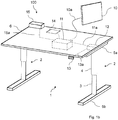
- Fig 1 a illustrates a height-adjustable table 100 comprising a table top 6 and a table stand 1.
- the table stand 1 comprises a height-adjusting arrangement.
- the height-adjusting arrangement comprises two legs 2 each comprising an inner tube 3 and an outer tube 4.
- the inner and the outer tubes 3, 4 are arranged for telescopic movement relative to each other.
- a linear actuator (not shown) is provided inside the tubes 3, 4.
- the linear actuator is in one end attached to the inner tube 3 and in the other end attached to the outer tube 4.
- the linear actuator provides the telescopic movement between the inner tube 3 and the outer tube 4 when the linear actuator is rotated.
- the leg 2 further comprises a top part 5a and a bottom part 5b.
- the top part 5a attaches the leg to the table top 6.
- the bottom part 5b functions as a foot for the table stand 1 when the table 100 stands on a surface.
- An electric motor 12 is connected to the linear actuator.
- the electric motor 12 rotates the linear actuator such that a linear telescopic movement of the inner tube 3 and the outer tube 4 is provided.
- the electric motor 12 is an electric direct current motor preferably adapted for a voltage in the range of 12-40 V.
- a control device 13 is provided for control of the operation of the electric motor 12.
- the control device 13 is mounted underneath the table top 6 for easy access for a user.
- the control device 13 is connected to the electric motor 12 via a cable 13a.
- the control device 13 is provided with two buttons, one for raising the table and one for lowering the table. The two buttons control the direction of rotation of the electric motor 12, and thereby the direction of rotation of the linear actuator. The linear actuator then elongates or retracts depending of the direction of rotation of the electric motor 12.
- the electric motor 12 is powered by a battery 11 via a cable 11a.
- the battery 11 is charged by a solar panel 10.
- the solar panel 10 is connected to the battery 11 via a cable 10a.
- the solar panel 10 is moveable relative to the battery 11, the electric motor 12 and the table top 6.
- the solar panel 10 may thereby be placed at various locations such as at a window, near a lamp or on the table top 6.
- the cable 10a has a length that provides a mobility of the solar panel 10 to a location separate from the table 100.
- the length of the cable 10a is preferably at least 2 meters.
- the cable 10a is only attached at its end portions. At one end portion, the cable 10a is attached to the solar panel 10, and at the other end portion the cable 10a is attached to the battery 11.
- the battery 11 is mounted on an underside of the table top 6.
- the battery 11 is connected to the electric motor 12.
- the battery 11 and the electric motor 12 could be placed in one integrated unit.
- the battery 11 may be provided with a connector (not shown) for connecting the battery 11 to a battery charger.
- the battery charger could charge the battery in a similar way as the solar panel 10 charges the battery 11.
- the battery charger may be connectable to a domestic electricity supply system.
- the battery 11 may further be provided with means for powering an additional device such as a computer, a lamp, a screen, a phone or the like.
- the power level in the battery 11 is monitored such that a predetermined power level is detected.
- the predetermined power level corresponds to a power level needed for powering the electric motor 12 during a raising or lowering operation of the height-adjustable table 1.
- the powering of any additional device is terminated. Thereby, there will always be a sufficient amount of power in the battery 11 even when the battery 11 also powers other devices than the electric motor 12.
- the battery 11 is charged by the solar panel 10 or a battery charger, such that the power level in the battery is above the predetermined power level, the powering of the additional device is switched back on.
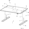
- Fig 1b illustrates a height-adjustable table 100 similar as in fig 1 a, wherein the table stand 1 is provided with an induction device 14.
- the induction device 14 is mounted on the table top 6 and connected to the battery 11.
- the induction device 14 is powered by the battery 11.
- the induction device 14 is used for powering a device adapted for induction powering.
- Such device adapted for induction powering may be a battery in an electric device such as a phone, a computer or the like.
- the powering of the induction device 14 and/or any other additional device is terminated. Thereby, there will always be a sufficient amount of power in the battery 11 even when the battery 11 also powers other devices than the electric motor 12.
- the battery 11 is charged by the solar panel 10 or a battery charger, such that the power level in the battery is above the predetermined power level, the powering of the additional device and/or the induction device is switch back on.
- the table stand 1 further comprises a power providing means 15 connected to the battery 11 via a cable 15a.
- the power providing means 15 is mounted on top of the table top 6.
- the power providing means may be provided with power sockets or other connecting means for connecting an additional device adapted to be powered via the power providing means 15.
- the power providing means 15 controls the powering of any additional device connected to the power providing means 15.
- the power providing means could also control the powering of the induction device 14.
- the power providing means 15 comprises a switch that enables or disables the powering of an additional device. The enabling and disabling of the powering of an additional device is performed as a response to the power level in the battery 11 reaching a predetermined level, or to that the electric motor 12 is operated.
- the switch disables the powering of an additional device when the battery level reaches below a first predetermined level. Further, the switch enables the powering of an additional device when the battery level reaches above a second predetermined level, wherein the second predetermined level is higher than the first predetermined level.
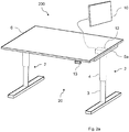
- Fig 1c illustrates a height-adjustable table 100 similar as in fig 1 a, not according to the invention, wherein the solar panel 10 is mounted on the table top 6.
- the solar panel 10 mounted on the table top 6 is connected to the battery 11 via a cable.
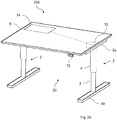
- Fig 2a illustrates a height-adjustable table 200 comprising a table top 6 and a height-adjustable table stand 20 with a height-adjusting arrangement comprising two legs 2, an electric motor 12 and a solar panel 10.
- the solar panel 10 is connected directly to the electric motor 12 via a cable.
- the solar panel 10 is moveable relative to the electric motor 12 and the table top 6.
- the solar panel 10 may be placed at various locations to receive light for producing electric current to the electric motor 12.
- the electric motor 12 is operated by the control device 13. When a button on the control device 13 is pressed, the electric motor 12 rotates the linear actuator in a leg 2.
- the electric current for the operation of the electric motor 12 is produced by the solar panel 10.
- Fig 2b illustrates a height-adjustable table 200 similar as in fig 2a , not according to the invention, wherein the solar panel 10 is mounted on the table top 6.
- the solar panel 10 mounted on the table top 6 is connected to the electric motor 12 via a cable.
Description
- The present disclosure relates to a height-adjustable table stand, and particularly a height-adjustable table stand powered by a solar cell panel.
- In known height-adjustable table stands, a height-adjusting arrangement is adapted to provide a vertical movement of the table stand by use of an electric motor. In
EP2019606 A2 , a height-adjustable table is disclosed, comprising an electric motor for providing vertical movement of a linear actuator, and control means for controlling the operation of the electric motor. - The height-adjusting arrangements in known table stands are supplied with electricity from a domestic electricity supply system, i.e. connected to a power socket. When furnishing a room or an office, the location of power sockets must be taken into consideration when placing the table stand. In some occasions, the table stand may not be possible to place at a wanted position due to the location of power sockets. Examples of electrically adjustable tables which include solar panels as a complement to domestic electricity supply systems are disclosed for example in
WO2010054656 A1 andUS2010064945 .US20090299689 disclose a height-adjustable table where the circuit board can be powered by a battery or solar cells.Consequently, there is a need for a height-adjustable table stand with a height-adjusting arrangement that is independent of power supply from a domestic electricity supply system. - It is an object of the present invention to provide an improved solution that alleviates the mentioned drawbacks with present devices. Furthermore, it is an object to provide a height-adjustable table stand that can be electrically operated independent of power supply from a domestic electricity supply system.
- This is achieved by providing a height-adjustable table stand comprising a height-adjusting arrangement for adjusting the height of the table stand, wherein the height-adjusting arrangement comprises at least one leg, each leg having an inner tubular member and an outer tubular member arranged for telescopic movement relative to each other. The height-adjusting arrangement further comprises a linear actuator coupled to said tubular members and adapted to provide the telescopic movement between the tubular members, an electric motor connected to the linear actuator and adapted to operate the linear actuator for providing telescopic movement between the tubular members, and a control device for controlling the operation of the electric motor. The table stand further comprises a solar panel connected to the height-adjusting arrangement for providing power to the electric motor.
- By providing the table stand with a solar panel for powering the electric motor, the table stand may be operated without any connection to a domestic electricity supply system, or to any other power source. When placing the table stand in a room, the placement may not be dependent on the location of power sockets in the room. The solar panel may be connected to the height-adjusting arrangement via a cable. The solar panel may be placed such that it receives sufficient light. The cable may be connected to the electric motor. The cable may be connected to the control device. The control device may provide electric current to the electric motor to control the operation of the electric motor. The control device may control the direction of rotation of the electric motor. The electric motor may be connected to the linear actuator in a leg. The electric motor may be connected to each linear actuator in each leg. When the electric motor is rotated, the linear actuator may be rotated such that it converts the rotational movement to a linear movement. The linear movement of the linear actuator may provide the telescopic movement between the inner and the outer tubular member in the leg. The electric motor may be adapted to be powered by an electric current provided by the solar panel. According to
claim 1, the height-adjusting arrangement further comprises a battery for storing power generated by the solar panel, and wherein the battery provides power to the electric motor. - By providing a battery between the solar panel and the electric motor, the solar panel may charge the battery during time when the electric motor is not operated. Most of the time, the electric motor is not operated, and thereby the solar panel may charge the battery during a long time before the power stored in the battery is needed for powering the electric motor. A solar panel with less capacity may be used with the height-adjusting arrangement when a battery stores the power generated by the solar panel, than if the solar panel would power the electric motor directly. Further, a stronger electric motor may be used, that needs more electric current than the current generated by the solar panel, when using a battery than if the solar panel would power the electric motor directly. Since the electric motor is used rather rarely and during a short period, the power stored in the battery may be used for other purposes, separate from the height-adjusting arrangement, during the time when the electric motor is not operated.
- In another embodiment, the table may further comprise a power providing means connected to the battery for providing power to an additional device, such as a computer.
- The additional device may further be other devices such as a lamp, a screen, a charger or the like. During the time when the electric motor is not operated the battery may provide power to an additional device, separate from the height-adjusting arrangement. For instance, the battery may charge a lap top computer during the time when the electric motor is not operated. The battery or the power providing means may be provided with means that controls that the battery does not provide power to an additional device if the power level in the battery is below a predetermined level. The predetermined power level may correspond to a power level needed for powering the electric motor such that the table stand may be raised or lowered. The power providing means may be provided with a switch that may enable or disable the powering of an additional device. The disabling of the powering of an additional device may be performed by the switch as a response to the power level in the battery reaching the predetermined level, or to the electric motor being operated. The enabling of the powering of an additional device may be performed by the switch as a response to the power level in the battery reaching above the predetermined level, or to the operation of the electric motor being terminated. The predetermined level may be two separate predetermined levels for the disabling and the enabling operation by the switch. The power providing means may be located adjacent to the battery. The power providing means may be a box provided with power sockets for connecting of an additional device. The power providing means may further be mounted on top of a table top attached to the table stand.
- In one embodiment, a predetermined power level of the battery may be set corresponding to an amount of power needed for a raising or lowering operation of the height-adjusting arrangement, and wherein the power providing means connected to the battery may be adapted to terminate the powering of an additional device when the predetermined power level of the battery is reached.
- When an additional device, such as a computer, a lamp, a screen, a charger or the like, is connected to the battery via the power providing means, the power level of the battery may be monitored, such that not all power in the battery is consumed. By setting a predetermined power level, corresponding to the power level needed for operating the height-adjusting arrangement, and terminating the powering of any additional device when that predetermined power level is reached, a scenario wherein the battery contains less power than needed for a height-adjusting operation may be avoided. The power providing means may be adapted to switch the powering of the additional device back on when the battery is charged such that the power level is above the predetermined power level. The powering of the additional device may be switch back on when the battery is charged to a power level that is a specified amount above the predetermined power level.
- In a further embodiment, the table may further comprise an induction device powered by the battery.
- The induction device may be used for powering a device adapted for induction powering. The induction device may provide a magnetic field such that an electric current is created in the device adapted for induction powering. The device adapted for induction powering may be a battery that is adapted for being charged by induction. The solar panel may then generate power that is used for powering a device adapted for induction powering. The table stand may be provided with a controlling means that control that the powering of the induction device is terminated when the power level in the battery is below a predetermined level. The controlling means may further terminate the powering of the induction device when the electric motor is operated.
- In one embodiment, the battery may further comprise means for coupling the battery to a battery charger for charging the battery.
- Thereby, the battery may be charged by a battery charger as well as by the solar panel. The power for charging the battery may be provided by a domestic electricity supply system. The battery may thereby temporarily be connected to a domestic electricity supply system for being charged.
- In a further embodiment, the solar panel may be mounted on a horizontal surface of the table. In this embodiment not falling under the scope of the claimed invention, the solar panel may thereby be attached to the table stand at a fixed position. The table stand may be provided with a table top, such that the fixed position of the solar panel may be at a horizontal surface of the table stand such as the table top. The position of the solar panel may be adapted for receiving a sufficient amount of light. According to
claim 1 the solar panel is movable relative to the height-adjusting arrangement. - Thereby, the solar panel may be placed at a location that is separated from the table stand. The solar panel may be placed at a location that is optimal for the solar panel to produce electric current. The solar panel may for instance be placed at a window to receive light. The solar panel may be connected to the height-adjusting arrangement via a cable. The solar panel may be provided with fastening means for arranging the solar panel at a location that provides sufficient light. The fastening means may adapt the solar panel to be arranged at a window to receive light.
- The invention will in the following be described in more detail with reference to the enclosed drawings, wherein:
-
Fig 1 a shows a perspective view of a table with a height-adjustable table stand according to an embodiment of the invention, -
Fig 1b shows a perspective view of a table with a height-adjustable table stand according to another embodiment of the invention, -
Fig 1c shows a perspective view of a table with a height-adjustable table stand according to yet another embodiment not according to the invention, -
Fig 2a shows a perspective view of a table with a height-adjustable table stand according to another embodiment of the invention, and -
Fig 2b shows a perspective view of a table with a height-adjustable table stand according to yet another embodiment not according to the invention. - The present invention will be described more fully hereinafter with reference to the accompanying drawings, in which preferred embodiments of the invention are shown. This invention may, however, be embodied in many different forms and should not be construed as limited to the embodiments set forth herein; rather, these embodiments are provided so that this disclosure will be thorough and complete, and will fully convey the scope of the invention to those skilled in the art. In the drawings, like numbers refer to like elements.
-
Fig 1 a illustrates a height-adjustable table 100 comprising atable top 6 and atable stand 1. The table stand 1 comprises a height-adjusting arrangement. The height-adjusting arrangement comprises twolegs 2 each comprising aninner tube 3 and anouter tube 4. The inner and theouter tubes tubes inner tube 3 and in the other end attached to theouter tube 4. The linear actuator provides the telescopic movement between theinner tube 3 and theouter tube 4 when the linear actuator is rotated. Theleg 2 further comprises atop part 5a and abottom part 5b. Thetop part 5a attaches the leg to thetable top 6. Thebottom part 5b functions as a foot for thetable stand 1 when the table 100 stands on a surface. - An
electric motor 12 is connected to the linear actuator. Theelectric motor 12 rotates the linear actuator such that a linear telescopic movement of theinner tube 3 and theouter tube 4 is provided. Theelectric motor 12 is an electric direct current motor preferably adapted for a voltage in the range of 12-40 V. - A
control device 13 is provided for control of the operation of theelectric motor 12. Thecontrol device 13 is mounted underneath thetable top 6 for easy access for a user. Thecontrol device 13 is connected to theelectric motor 12 via acable 13a. Thecontrol device 13 is provided with two buttons, one for raising the table and one for lowering the table. The two buttons control the direction of rotation of theelectric motor 12, and thereby the direction of rotation of the linear actuator. The linear actuator then elongates or retracts depending of the direction of rotation of theelectric motor 12. - The
electric motor 12 is powered by abattery 11 via acable 11a. Thebattery 11 is charged by asolar panel 10. Thesolar panel 10 is connected to thebattery 11 via acable 10a. Thesolar panel 10 is moveable relative to thebattery 11, theelectric motor 12 and thetable top 6. Thesolar panel 10 may thereby be placed at various locations such as at a window, near a lamp or on thetable top 6. Thecable 10a has a length that provides a mobility of thesolar panel 10 to a location separate from the table 100. The length of thecable 10a is preferably at least 2 meters. Thecable 10a is only attached at its end portions. At one end portion, thecable 10a is attached to thesolar panel 10, and at the other end portion thecable 10a is attached to thebattery 11. - The
battery 11 is mounted on an underside of thetable top 6. Thebattery 11 is connected to theelectric motor 12. Thebattery 11 and theelectric motor 12 could be placed in one integrated unit. Thebattery 11 may be provided with a connector (not shown) for connecting thebattery 11 to a battery charger. The battery charger could charge the battery in a similar way as thesolar panel 10 charges thebattery 11. The battery charger may be connectable to a domestic electricity supply system. Thebattery 11 may further be provided with means for powering an additional device such as a computer, a lamp, a screen, a phone or the like. - When the
electric motor 12 is operated via thecontrol device 13, the powering of an additional device is disconnected. Thereby, all available power in thebattery 11 and from thesolar panel 10 is available for theelectric motor 12. - Further, the power level in the
battery 11 is monitored such that a predetermined power level is detected. The predetermined power level corresponds to a power level needed for powering theelectric motor 12 during a raising or lowering operation of the height-adjustable table 1. When the predetermined power level in thebattery 11 is detected, the powering of any additional device is terminated. Thereby, there will always be a sufficient amount of power in thebattery 11 even when thebattery 11 also powers other devices than theelectric motor 12. When thebattery 11 is charged by thesolar panel 10 or a battery charger, such that the power level in the battery is above the predetermined power level, the powering of the additional device is switched back on. -
Fig 1b illustrates a height-adjustable table 100 similar as infig 1 a, wherein thetable stand 1 is provided with aninduction device 14. Theinduction device 14 is mounted on thetable top 6 and connected to thebattery 11. Theinduction device 14 is powered by thebattery 11. Theinduction device 14 is used for powering a device adapted for induction powering. Such device adapted for induction powering may be a battery in an electric device such as a phone, a computer or the like. - When the
electric motor 12 is operated via thecontrol device 13, the powering of an additional device and/or the induction device is disconnected. Thereby, all available power in thebattery 11 and from thesolar panel 10 is available for theelectric motor 12. - When the predetermined power level in the
battery 11 is detected, the powering of theinduction device 14 and/or any other additional device is terminated. Thereby, there will always be a sufficient amount of power in thebattery 11 even when thebattery 11 also powers other devices than theelectric motor 12. When thebattery 11 is charged by thesolar panel 10 or a battery charger, such that the power level in the battery is above the predetermined power level, the powering of the additional device and/or the induction device is switch back on. - The table stand 1 further comprises a power providing means 15 connected to the
battery 11 via acable 15a. The power providing means 15 is mounted on top of thetable top 6. The power providing means may be provided with power sockets or other connecting means for connecting an additional device adapted to be powered via the power providing means 15. The power providing means 15 controls the powering of any additional device connected to the power providing means 15. The power providing means could also control the powering of theinduction device 14. The power providing means 15 comprises a switch that enables or disables the powering of an additional device. The enabling and disabling of the powering of an additional device is performed as a response to the power level in thebattery 11 reaching a predetermined level, or to that theelectric motor 12 is operated. In one embodiment, the switch disables the powering of an additional device when the battery level reaches below a first predetermined level. Further, the switch enables the powering of an additional device when the battery level reaches above a second predetermined level, wherein the second predetermined level is higher than the first predetermined level. -
Fig 1c illustrates a height-adjustable table 100 similar as infig 1 a, not according to the invention, wherein thesolar panel 10 is mounted on thetable top 6. Thesolar panel 10 mounted on thetable top 6 is connected to thebattery 11 via a cable. -
Fig 2a illustrates a height-adjustable table 200 comprising atable top 6 and a height-adjustable table stand 20 with a height-adjusting arrangement comprising twolegs 2, anelectric motor 12 and asolar panel 10. Thesolar panel 10 is connected directly to theelectric motor 12 via a cable. Thesolar panel 10 is moveable relative to theelectric motor 12 and thetable top 6. Thesolar panel 10 may be placed at various locations to receive light for producing electric current to theelectric motor 12. Theelectric motor 12 is operated by thecontrol device 13. When a button on thecontrol device 13 is pressed, theelectric motor 12 rotates the linear actuator in aleg 2. The electric current for the operation of theelectric motor 12 is produced by thesolar panel 10. -
Fig 2b illustrates a height-adjustable table 200 similar as infig 2a , not according to the invention, wherein thesolar panel 10 is mounted on thetable top 6. Thesolar panel 10 mounted on thetable top 6 is connected to theelectric motor 12 via a cable. - In the drawings and specification, there have been disclosed preferred embodiments and examples of the invention and, although specific terms are employed, they are used in a generic and descriptive sense only and not for the purpose of limitation, the scope of the invention being set forth in the following claims.
Claims (6)
- A height-adjustable table stand (1, 20) comprising,
a table top, and
a height-adjusting arrangement for adjusting the height of the table stand, wherein the height-adjusting arrangement comprises,at least one leg (2), each leg having an inner tubular member (3) and an outer tubular member (4) arranged for telescopic movement relative to each other,a linear actuator coupled to said tubular members (3, 4) and adapted to provide the telescopic movement between the tubular members,an electric motor (12) connected to the linear actuator and adapted to operate the linear actuator for providing telescopic movement between the tubular members (3, 4), anda control device (13) for controlling the operation of the electric motor (12), and whereinthe table stand further comprises a solar panel (10) connected to the height-adjusting arrangement for providing power to the electric motor (12),characterized in that
the height-adjusting arrangement further comprises a battery (11) for storing power generated by the solar panel (10), and wherein the battery provides power to the electric motor (12), and
the solar panel is movable relative to the battery, the electric motor and the table top. - Height-adjustable table stand according to claim 1, wherein the table stand (1, 20) further comprises a power providing means (15) connected to the battery (11) for providing power to an additional device, such as a computer.
- Height-adjustable table stand according to claim 2, wherein a predetermined power level of the battery (11) is set, and wherein the power providing means connected to the battery is adapted to terminate the powering of an additional device when battery power reaches the predetermined power level.
- Height-adjustable table stand according to any of the claims 1-3, wherein the table stand (1, 20) further comprises an induction device (14) powered by the battery (11).
- Height-adjustable table stand according to any of the claims 1-4, wherein the battery (11) further comprises means for coupling the battery to a battery charger for charging the battery.
- Height-adjustable table stand according to any of the claims 1-5, wherein the solar panel (10) is movable relative to the height-adjusting arrangement.
Priority Applications (7)
| Application Number | Priority Date | Filing Date | Title |
|---|---|---|---|
| ES10192245.8T ES2666551T3 (en) | 2010-11-23 | 2010-11-23 | Adjustable height table stand |
| NO10192245A NO2454969T3 (en) | 2010-11-23 | 2010-11-23 | |
| DK10192245.8T DK2454969T3 (en) | 2010-11-23 | 2010-11-23 | Height adjustable table |
| PL10192245T PL2454969T3 (en) | 2010-11-23 | 2010-11-23 | Height-adjustable table stand |
| LTEP10192245.8T LT2454969T (en) | 2010-11-23 | 2010-11-23 | Height-adjustable table stand |
| EP10192245.8A EP2454969B1 (en) | 2010-11-23 | 2010-11-23 | Height-adjustable table stand |
| US13/286,367 US10045610B2 (en) | 2010-11-23 | 2011-11-01 | Height adjustable table stand |
Applications Claiming Priority (1)
| Application Number | Priority Date | Filing Date | Title |
|---|---|---|---|
| EP10192245.8A EP2454969B1 (en) | 2010-11-23 | 2010-11-23 | Height-adjustable table stand |
Publications (2)
| Publication Number | Publication Date |
|---|---|
| EP2454969A1 EP2454969A1 (en) | 2012-05-23 |
| EP2454969B1 true EP2454969B1 (en) | 2018-02-28 |
Family
ID=43828135
Family Applications (1)
| Application Number | Title | Priority Date | Filing Date |
|---|---|---|---|
| EP10192245.8A Active EP2454969B1 (en) | 2010-11-23 | 2010-11-23 | Height-adjustable table stand |
Country Status (7)
| Country | Link |
|---|---|
| US (1) | US10045610B2 (en) |
| EP (1) | EP2454969B1 (en) |
| DK (1) | DK2454969T3 (en) |
| ES (1) | ES2666551T3 (en) |
| LT (1) | LT2454969T (en) |
| NO (1) | NO2454969T3 (en) |
| PL (1) | PL2454969T3 (en) |
Families Citing this family (42)
| Publication number | Priority date | Publication date | Assignee | Title |
|---|---|---|---|---|
| US10506898B2 (en) * | 2005-12-09 | 2019-12-17 | Maureen P. Herbst | Bathtub table |
| WO2013176690A1 (en) | 2012-05-24 | 2013-11-28 | Gemmy Industries Corporation | Adjustable desktop platform |
| DE202012008994U1 (en) * | 2012-09-19 | 2014-01-09 | Grass Gmbh | Furniture and device for controlling movement of a furniture part |
| USD732317S1 (en) * | 2014-02-14 | 2015-06-23 | Chien-Kuo Chang | Desk |
| CN103929123B (en) * | 2014-04-27 | 2016-04-06 | 重庆工业职业技术学院 | The portable folding office platform that solar panel rotates with the sun can be made |
| USD790268S1 (en) * | 2014-09-19 | 2017-06-27 | Unifor S.P.A. | Structure for a height-adjustable table |
| CN104433206A (en) * | 2014-11-29 | 2015-03-25 | 河南新乐电器有限公司 | Liftable electric heating table |
| USD795619S1 (en) * | 2015-01-21 | 2017-08-29 | Stirworks Inc. | Desk with legs |
| USD795620S1 (en) * | 2015-01-21 | 2017-08-29 | Stirworks Inc. | Desk with feet |
| KR102053015B1 (en) * | 2015-04-23 | 2020-01-08 | 티모션 테크놀로지 코., 엘티디. | Electrical Adjustable Table and Control Method for Electrical Adjustable Table |
| USD794982S1 (en) * | 2016-04-14 | 2017-08-22 | Williams-Sonoma, Inc. | Desk |
| JP1571594S (en) * | 2016-06-07 | 2017-03-13 | ||
| USD837573S1 (en) * | 2016-06-28 | 2019-01-08 | Konecranes Global Corporation | Workstation |
| US20180078134A1 (en) | 2016-09-17 | 2018-03-22 | Globechek, Llc | Eye examination kiosk system and method for remote eye examination |
| US11019920B2 (en) | 2016-09-23 | 2021-06-01 | Varidesk, Llc | Electrically-lifted computer desk and office desk thereof |
| CN206390562U (en) | 2016-09-23 | 2017-08-11 | 廖良成 | Electric lifting computer desk and its desk |
| US11058216B2 (en) * | 2016-09-26 | 2021-07-13 | Kessebohmer Produktions Gmbh & Co. Kg | Control of a height adjustable table using fingerprints |
| JP1585173S (en) * | 2016-10-06 | 2017-09-04 | ||
| US10258150B2 (en) * | 2016-12-27 | 2019-04-16 | Yi-Cheng Tseng | Height adjustable desk |
| US10791826B2 (en) * | 2017-03-31 | 2020-10-06 | Twin-Star International, Inc. | Adjustable height desk system |
| CA3056300A1 (en) * | 2017-05-15 | 2018-11-22 | Linak A/S | Height-adjustable table |
| USD825239S1 (en) * | 2017-06-07 | 2018-08-14 | Okamura Corporation | Desk |
| US10413063B2 (en) | 2017-08-14 | 2019-09-17 | Knoll, Inc. | Table connection mechanism and method of using the same |
| CN208434914U (en) * | 2017-08-29 | 2019-01-29 | 第一传动科技股份有限公司 | Platform lifting device |
| TWM558564U (en) * | 2017-11-02 | 2018-04-21 | Zheng zhong sheng | Smart table |
| US10390611B2 (en) | 2017-11-15 | 2019-08-27 | Knoll, Inc. | Privacy screen table connection mechanism |
| DE102018104195A1 (en) * | 2018-02-23 | 2019-08-29 | Logicdata Electronic & Software Entwicklungs Gmbh | Furniture, method for calibrating an actuator and method for adjusting a component of a piece of furniture |
| CN114376335A (en) * | 2018-04-16 | 2022-04-22 | 游乐场商店有限公司 | Table system |
| US10779638B2 (en) | 2018-06-04 | 2020-09-22 | Knoll, Inc. | Table height adjustment system and method of using the same |
| US10588401B1 (en) * | 2018-12-20 | 2020-03-17 | Dong Guan Song Wei Electric Technology Co., Ltd. | Height-adjustable multifunctional table |
| US10555602B1 (en) * | 2018-12-20 | 2020-02-11 | Dong Guan Song Wei Electric Technology Co., Ltd. | Height-adjustable table |
| US11304508B2 (en) * | 2019-01-08 | 2022-04-19 | OMT—VEYHL USA Corporation | Height adjustable table and components of same |
| MX2021013032A (en) | 2019-04-25 | 2022-02-10 | Ergotron Inc | Height adjustable workstations with zero idle power. |
| TWM601047U (en) * | 2019-05-15 | 2020-09-11 | 第一傳動科技股份有限公司 | Mechatronics electric table stand |
| USD913733S1 (en) | 2020-05-18 | 2021-03-23 | Knoll, Inc. | Shelving unit |
| USD947579S1 (en) * | 2020-06-15 | 2022-04-05 | zhejiang zhongwei smart furniture Co., LTD | Electric lift table |
| US11549537B2 (en) | 2020-06-19 | 2023-01-10 | Knoll, Inc. | Article of furniture and method of installing same |
| USD961962S1 (en) * | 2020-07-02 | 2022-08-30 | Yajun Hun | Gaming desk |
| USD950986S1 (en) * | 2020-07-13 | 2022-05-10 | Yajun Hu | Height adjustable desk |
| USD966015S1 (en) * | 2020-08-03 | 2022-10-11 | Ningbo Yuanjing Electronic Technology Co., Ltd | Desk |
| US11944208B2 (en) | 2021-06-14 | 2024-04-02 | Knoll, Inc. | Chair and method of making the chair |
| US11877646B2 (en) | 2021-07-12 | 2024-01-23 | Knoll, Inc. | Work surface attachment mechanism, article of furniture, and method of making the article of furniture |
Citations (3)
| Publication number | Priority date | Publication date | Assignee | Title |
|---|---|---|---|---|
| EP2019606A2 (en) * | 2006-05-01 | 2009-02-04 | Linak A/S | Electrically adjustable piece of furniture |
| US20090212638A1 (en) * | 2008-02-25 | 2009-08-27 | L & P Property Management Company | Inductively coupled work surfaces |
| US20090299689A1 (en) * | 2008-06-02 | 2009-12-03 | David Robert Stubben | Portable Leveling Table |
Family Cites Families (7)
| Publication number | Priority date | Publication date | Assignee | Title |
|---|---|---|---|---|
| CH664434A5 (en) * | 1984-02-20 | 1988-02-29 | Magnetic Elektromotoren Ag | TELESCOPIC COLUMN WITH ELECTRIC MOTOR DRIVE AND FURNITURE WITH THE TELESCOPIC COLUMN AS A FOOT. |
| US6682030B2 (en) * | 2001-03-08 | 2004-01-27 | Lista International Corporation | Workstation with adjustable height frame |
| US7098807B2 (en) * | 2003-11-19 | 2006-08-29 | 9076-0935 Quebec Inc. | Traffic-signaling system |
| US7507151B1 (en) * | 2006-05-12 | 2009-03-24 | University Of Central Florida Research Foundation, Inc. | High efficiency solar powered fan |
| NL2001472C2 (en) * | 2008-04-11 | 2009-10-13 | Vehold B V | Adjustment device. |
| US20100064945A1 (en) * | 2008-05-30 | 2010-03-18 | Golden Sun Solar Lighting And Tchnolgoy Co. Ltd | Table With Solar Power Module |
| WO2010054656A1 (en) * | 2008-11-13 | 2010-05-20 | Linak A/S | Article of electrically adjustable furniture, such as a table, bed or reclining chair |
-
2010
- 2010-11-23 NO NO10192245A patent/NO2454969T3/no unknown
- 2010-11-23 LT LTEP10192245.8T patent/LT2454969T/en unknown
- 2010-11-23 PL PL10192245T patent/PL2454969T3/en unknown
- 2010-11-23 ES ES10192245.8T patent/ES2666551T3/en active Active
- 2010-11-23 EP EP10192245.8A patent/EP2454969B1/en active Active
- 2010-11-23 DK DK10192245.8T patent/DK2454969T3/en active
-
2011
- 2011-11-01 US US13/286,367 patent/US10045610B2/en active Active
Patent Citations (3)
| Publication number | Priority date | Publication date | Assignee | Title |
|---|---|---|---|---|
| EP2019606A2 (en) * | 2006-05-01 | 2009-02-04 | Linak A/S | Electrically adjustable piece of furniture |
| US20090212638A1 (en) * | 2008-02-25 | 2009-08-27 | L & P Property Management Company | Inductively coupled work surfaces |
| US20090299689A1 (en) * | 2008-06-02 | 2009-12-03 | David Robert Stubben | Portable Leveling Table |
Also Published As
| Publication number | Publication date |
|---|---|
| LT2454969T (en) | 2018-05-10 |
| ES2666551T3 (en) | 2018-05-07 |
| PL2454969T3 (en) | 2018-07-31 |
| NO2454969T3 (en) | 2018-07-28 |
| EP2454969A1 (en) | 2012-05-23 |
| US10045610B2 (en) | 2018-08-14 |
| US20120126072A1 (en) | 2012-05-24 |
| DK2454969T3 (en) | 2018-05-07 |
Similar Documents
| Publication | Publication Date | Title |
|---|---|---|
| EP2454969B1 (en) | Height-adjustable table stand | |
| JP3219564U (en) | Smart table | |
| US10263373B2 (en) | Portable tower with electrical outlets | |
| CN210123909U (en) | Furniture system | |
| US9084475B2 (en) | Height adjustable piece of furniture with zero stand-by power consumption | |
| US7786622B2 (en) | Juvenile product inductive power transfer | |
| US20040026998A1 (en) | Low voltage electrified furniture unit | |
| US20150026890A1 (en) | Emergency power supply device for an electromotive furniture drive for a piece of furniture, electromotive furniture drive, and a corresponding piece of furniture | |
| CN205813956U (en) | Desk | |
| US20130036914A1 (en) | Machine for the preparation of beverages, in particular coffee | |
| JP7442105B2 (en) | power supply stand | |
| WO2010102629A2 (en) | Actuator system | |
| KR200481061Y1 (en) | Wireless Rechargeable Table | |
| KR20110095024A (en) | Potable receptacle for family use | |
| CN215498316U (en) | Portable power box for navigation aid lamp | |
| CN209300414U (en) | A kind of Intelligent movable desk | |
| CN220174698U (en) | Electricity taking device of electric lifting table | |
| CN215225418U (en) | Intelligent lifting executive desk | |
| WO2014183766A1 (en) | Actuator system | |
| US20200036202A1 (en) | Piece of furniture and electromotive furniture drive comprising a charging apparatus | |
| CN205725098U (en) | 86 type wireless charging panels | |
| CN217090030U (en) | Intelligent mirror cabinet | |
| CN220777750U (en) | Electric heating table with portable power source | |
| CN220551276U (en) | Vertical fan | |
| CN202503317U (en) | Portable standby power supply with bracket |
Legal Events
| Date | Code | Title | Description |
|---|---|---|---|
| PUAI | Public reference made under article 153(3) epc to a published international application that has entered the european phase |
Free format text: ORIGINAL CODE: 0009012 |
|
| AK | Designated contracting states |
Kind code of ref document: A1 Designated state(s): AL AT BE BG CH CY CZ DE DK EE ES FI FR GB GR HR HU IE IS IT LI LT LU LV MC MK MT NL NO PL PT RO RS SE SI SK SM TR |
|
| AX | Request for extension of the european patent |
Extension state: BA ME |
|
| 17P | Request for examination filed |
Effective date: 20121122 |
|
| 17Q | First examination report despatched |
Effective date: 20170328 |
|
| GRAP | Despatch of communication of intention to grant a patent |
Free format text: ORIGINAL CODE: EPIDOSNIGR1 |
|
| INTG | Intention to grant announced |
Effective date: 20170928 |
|
| GRAS | Grant fee paid |
Free format text: ORIGINAL CODE: EPIDOSNIGR3 |
|
| GRAA | (expected) grant |
Free format text: ORIGINAL CODE: 0009210 |
|
| AK | Designated contracting states |
Kind code of ref document: B1 Designated state(s): AL AT BE BG CH CY CZ DE DK EE ES FI FR GB GR HR HU IE IS IT LI LT LU LV MC MK MT NL NO PL PT RO RS SE SI SK SM TR |
|
| REG | Reference to a national code |
Ref country code: GB Ref legal event code: FG4D Ref country code: CH Ref legal event code: EP |
|
| REG | Reference to a national code |
Ref country code: AT Ref legal event code: REF Ref document number: 973186 Country of ref document: AT Kind code of ref document: T Effective date: 20180315 |
|
| REG | Reference to a national code |
Ref country code: IE Ref legal event code: FG4D |
|
| REG | Reference to a national code |
Ref country code: DE Ref legal event code: R096 Ref document number: 602010048784 Country of ref document: DE |
|
| REG | Reference to a national code |
Ref country code: CH Ref legal event code: NV Representative=s name: WEINMANN ZIMMERLI, CH |
|
| REG | Reference to a national code |
Ref country code: DK Ref legal event code: T3 Effective date: 20180502 Ref country code: ES Ref legal event code: FG2A Ref document number: 2666551 Country of ref document: ES Kind code of ref document: T3 Effective date: 20180507 |
|
| REG | Reference to a national code |
Ref country code: SE Ref legal event code: TRGR |
|
| REG | Reference to a national code |
Ref country code: NL Ref legal event code: FP |
|
| REG | Reference to a national code |
Ref country code: NO Ref legal event code: T2 Effective date: 20180228 |
|
| REG | Reference to a national code |
Ref country code: EE Ref legal event code: FG4A Ref document number: E015417 Country of ref document: EE Effective date: 20180604 |
|
| PG25 | Lapsed in a contracting state [announced via postgrant information from national office to epo] |
Ref country code: HR Free format text: LAPSE BECAUSE OF FAILURE TO SUBMIT A TRANSLATION OF THE DESCRIPTION OR TO PAY THE FEE WITHIN THE PRESCRIBED TIME-LIMIT Effective date: 20180228 Ref country code: CY Free format text: LAPSE BECAUSE OF FAILURE TO SUBMIT A TRANSLATION OF THE DESCRIPTION OR TO PAY THE FEE WITHIN THE PRESCRIBED TIME-LIMIT Effective date: 20180228 |
|
| PG25 | Lapsed in a contracting state [announced via postgrant information from national office to epo] |
Ref country code: GR Free format text: LAPSE BECAUSE OF FAILURE TO SUBMIT A TRANSLATION OF THE DESCRIPTION OR TO PAY THE FEE WITHIN THE PRESCRIBED TIME-LIMIT Effective date: 20180529 Ref country code: BG Free format text: LAPSE BECAUSE OF FAILURE TO SUBMIT A TRANSLATION OF THE DESCRIPTION OR TO PAY THE FEE WITHIN THE PRESCRIBED TIME-LIMIT Effective date: 20180528 Ref country code: RS Free format text: LAPSE BECAUSE OF FAILURE TO SUBMIT A TRANSLATION OF THE DESCRIPTION OR TO PAY THE FEE WITHIN THE PRESCRIBED TIME-LIMIT Effective date: 20180228 |
|
| PG25 | Lapsed in a contracting state [announced via postgrant information from national office to epo] |
Ref country code: RO Free format text: LAPSE BECAUSE OF FAILURE TO SUBMIT A TRANSLATION OF THE DESCRIPTION OR TO PAY THE FEE WITHIN THE PRESCRIBED TIME-LIMIT Effective date: 20180228 Ref country code: AL Free format text: LAPSE BECAUSE OF FAILURE TO SUBMIT A TRANSLATION OF THE DESCRIPTION OR TO PAY THE FEE WITHIN THE PRESCRIBED TIME-LIMIT Effective date: 20180228 |
|
| REG | Reference to a national code |
Ref country code: DE Ref legal event code: R097 Ref document number: 602010048784 Country of ref document: DE |
|
| PG25 | Lapsed in a contracting state [announced via postgrant information from national office to epo] |
Ref country code: CZ Free format text: LAPSE BECAUSE OF FAILURE TO SUBMIT A TRANSLATION OF THE DESCRIPTION OR TO PAY THE FEE WITHIN THE PRESCRIBED TIME-LIMIT Effective date: 20180228 Ref country code: SK Free format text: LAPSE BECAUSE OF FAILURE TO SUBMIT A TRANSLATION OF THE DESCRIPTION OR TO PAY THE FEE WITHIN THE PRESCRIBED TIME-LIMIT Effective date: 20180228 Ref country code: SM Free format text: LAPSE BECAUSE OF FAILURE TO SUBMIT A TRANSLATION OF THE DESCRIPTION OR TO PAY THE FEE WITHIN THE PRESCRIBED TIME-LIMIT Effective date: 20180228 |
|
| PLBE | No opposition filed within time limit |
Free format text: ORIGINAL CODE: 0009261 |
|
| STAA | Information on the status of an ep patent application or granted ep patent |
Free format text: STATUS: NO OPPOSITION FILED WITHIN TIME LIMIT |
|
| 26N | No opposition filed |
Effective date: 20181129 |
|
| PG25 | Lapsed in a contracting state [announced via postgrant information from national office to epo] |
Ref country code: SI Free format text: LAPSE BECAUSE OF FAILURE TO SUBMIT A TRANSLATION OF THE DESCRIPTION OR TO PAY THE FEE WITHIN THE PRESCRIBED TIME-LIMIT Effective date: 20180228 |
|
| PG25 | Lapsed in a contracting state [announced via postgrant information from national office to epo] |
Ref country code: MC Free format text: LAPSE BECAUSE OF FAILURE TO SUBMIT A TRANSLATION OF THE DESCRIPTION OR TO PAY THE FEE WITHIN THE PRESCRIBED TIME-LIMIT Effective date: 20180228 Ref country code: LU Free format text: LAPSE BECAUSE OF NON-PAYMENT OF DUE FEES Effective date: 20181123 |
|
| REG | Reference to a national code |
Ref country code: IE Ref legal event code: MM4A |
|
| PG25 | Lapsed in a contracting state [announced via postgrant information from national office to epo] |
Ref country code: IE Free format text: LAPSE BECAUSE OF NON-PAYMENT OF DUE FEES Effective date: 20181123 |
|
| PG25 | Lapsed in a contracting state [announced via postgrant information from national office to epo] |
Ref country code: MT Free format text: LAPSE BECAUSE OF NON-PAYMENT OF DUE FEES Effective date: 20181123 |
|
| PGFP | Annual fee paid to national office [announced via postgrant information from national office to epo] |
Ref country code: NL Payment date: 20191129 Year of fee payment: 10 Ref country code: NO Payment date: 20191202 Year of fee payment: 10 Ref country code: LT Payment date: 20191203 Year of fee payment: 10 Ref country code: FI Payment date: 20191220 Year of fee payment: 10 |
|
| PGFP | Annual fee paid to national office [announced via postgrant information from national office to epo] |
Ref country code: BE Payment date: 20191126 Year of fee payment: 10 Ref country code: LV Payment date: 20191129 Year of fee payment: 10 Ref country code: ES Payment date: 20191218 Year of fee payment: 10 Ref country code: FR Payment date: 20191129 Year of fee payment: 10 Ref country code: EE Payment date: 20191202 Year of fee payment: 10 Ref country code: PL Payment date: 20191118 Year of fee payment: 10 |
|
| PG25 | Lapsed in a contracting state [announced via postgrant information from national office to epo] |
Ref country code: TR Free format text: LAPSE BECAUSE OF FAILURE TO SUBMIT A TRANSLATION OF THE DESCRIPTION OR TO PAY THE FEE WITHIN THE PRESCRIBED TIME-LIMIT Effective date: 20180228 |
|
| PGFP | Annual fee paid to national office [announced via postgrant information from national office to epo] |
Ref country code: CH Payment date: 20191219 Year of fee payment: 10 |
|
| PGFP | Annual fee paid to national office [announced via postgrant information from national office to epo] |
Ref country code: GB Payment date: 20191218 Year of fee payment: 10 |
|
| PG25 | Lapsed in a contracting state [announced via postgrant information from national office to epo] |
Ref country code: PT Free format text: LAPSE BECAUSE OF FAILURE TO SUBMIT A TRANSLATION OF THE DESCRIPTION OR TO PAY THE FEE WITHIN THE PRESCRIBED TIME-LIMIT Effective date: 20180228 |
|
| PG25 | Lapsed in a contracting state [announced via postgrant information from national office to epo] |
Ref country code: MK Free format text: LAPSE BECAUSE OF NON-PAYMENT OF DUE FEES Effective date: 20180228 Ref country code: HU Free format text: LAPSE BECAUSE OF FAILURE TO SUBMIT A TRANSLATION OF THE DESCRIPTION OR TO PAY THE FEE WITHIN THE PRESCRIBED TIME-LIMIT; INVALID AB INITIO Effective date: 20101123 |
|
| PG25 | Lapsed in a contracting state [announced via postgrant information from national office to epo] |
Ref country code: IS Free format text: LAPSE BECAUSE OF FAILURE TO SUBMIT A TRANSLATION OF THE DESCRIPTION OR TO PAY THE FEE WITHIN THE PRESCRIBED TIME-LIMIT Effective date: 20180628 |
|
| REG | Reference to a national code |
Ref country code: DE Ref legal event code: R081 Ref document number: 602010048784 Country of ref document: DE Owner name: ROL AB, SE Free format text: FORMER OWNER: KIH-UTVECKLING AB, JOENKOEPING, SE |
|
| REG | Reference to a national code |
Ref country code: AT Ref legal event code: PC Ref document number: 973186 Country of ref document: AT Kind code of ref document: T Owner name: ROL AB, SE Effective date: 20210305 Ref country code: AT Ref legal event code: UEP Ref document number: 973186 Country of ref document: AT Kind code of ref document: T Effective date: 20180228 |
|
| REG | Reference to a national code |
Ref country code: EE Ref legal event code: MM4A Ref document number: E015417 Country of ref document: EE Effective date: 20201130 Ref country code: FI Ref legal event code: MAE |
|
| REG | Reference to a national code |
Ref country code: NO Ref legal event code: MMEP |
|
| REG | Reference to a national code |
Ref country code: CH Ref legal event code: PL |
|
| REG | Reference to a national code |
Ref country code: NL Ref legal event code: MM Effective date: 20201201 |
|
| GBPC | Gb: european patent ceased through non-payment of renewal fee |
Effective date: 20201123 |
|
| PG25 | Lapsed in a contracting state [announced via postgrant information from national office to epo] |
Ref country code: NO Free format text: LAPSE BECAUSE OF NON-PAYMENT OF DUE FEES Effective date: 20201130 Ref country code: EE Free format text: LAPSE BECAUSE OF NON-PAYMENT OF DUE FEES Effective date: 20201130 Ref country code: FI Free format text: LAPSE BECAUSE OF NON-PAYMENT OF DUE FEES Effective date: 20201123 |
|
| REG | Reference to a national code |
Ref country code: BE Ref legal event code: MM Effective date: 20201130 |
|
| PG25 | Lapsed in a contracting state [announced via postgrant information from national office to epo] |
Ref country code: LI Free format text: LAPSE BECAUSE OF NON-PAYMENT OF DUE FEES Effective date: 20201130 Ref country code: CH Free format text: LAPSE BECAUSE OF NON-PAYMENT OF DUE FEES Effective date: 20201130 Ref country code: NL Free format text: LAPSE BECAUSE OF NON-PAYMENT OF DUE FEES Effective date: 20201201 Ref country code: LV Free format text: LAPSE BECAUSE OF NON-PAYMENT OF DUE FEES Effective date: 20201123 |
|
| REG | Reference to a national code |
Ref country code: LT Ref legal event code: MM4D Effective date: 20201123 |
|
| PG25 | Lapsed in a contracting state [announced via postgrant information from national office to epo] |
Ref country code: LT Free format text: LAPSE BECAUSE OF NON-PAYMENT OF DUE FEES Effective date: 20201123 Ref country code: FR Free format text: LAPSE BECAUSE OF NON-PAYMENT OF DUE FEES Effective date: 20201130 |
|
| PG25 | Lapsed in a contracting state [announced via postgrant information from national office to epo] |
Ref country code: GB Free format text: LAPSE BECAUSE OF NON-PAYMENT OF DUE FEES Effective date: 20201123 |
|
| REG | Reference to a national code |
Ref country code: ES Ref legal event code: FD2A Effective date: 20220202 |
|
| PG25 | Lapsed in a contracting state [announced via postgrant information from national office to epo] |
Ref country code: ES Free format text: LAPSE BECAUSE OF NON-PAYMENT OF DUE FEES Effective date: 20201124 |
|
| PG25 | Lapsed in a contracting state [announced via postgrant information from national office to epo] |
Ref country code: BE Free format text: LAPSE BECAUSE OF NON-PAYMENT OF DUE FEES Effective date: 20201130 |
|
| PG25 | Lapsed in a contracting state [announced via postgrant information from national office to epo] |
Ref country code: PL Free format text: LAPSE BECAUSE OF NON-PAYMENT OF DUE FEES Effective date: 20201123 |
|
| PGFP | Annual fee paid to national office [announced via postgrant information from national office to epo] |
Ref country code: SE Payment date: 20231016 Year of fee payment: 14 Ref country code: IT Payment date: 20231017 Year of fee payment: 14 Ref country code: DK Payment date: 20231013 Year of fee payment: 14 Ref country code: DE Payment date: 20231018 Year of fee payment: 14 Ref country code: AT Payment date: 20231017 Year of fee payment: 14 |