EP2454470B1 - Method of applying abrasion resistant materials to rotors - Google Patents
Method of applying abrasion resistant materials to rotors Download PDFInfo
- Publication number
- EP2454470B1 EP2454470B1 EP09847438.0A EP09847438A EP2454470B1 EP 2454470 B1 EP2454470 B1 EP 2454470B1 EP 09847438 A EP09847438 A EP 09847438A EP 2454470 B1 EP2454470 B1 EP 2454470B1
- Authority
- EP
- European Patent Office
- Prior art keywords
- abrasion resistant
- rotor
- coat
- resistant material
- elastomeric
- Prior art date
- Legal status (The legal status is an assumption and is not a legal conclusion. Google has not performed a legal analysis and makes no representation as to the accuracy of the status listed.)
- Active
Links
Images



Classifications
-
- F—MECHANICAL ENGINEERING; LIGHTING; HEATING; WEAPONS; BLASTING
- F01—MACHINES OR ENGINES IN GENERAL; ENGINE PLANTS IN GENERAL; STEAM ENGINES
- F01D—NON-POSITIVE DISPLACEMENT MACHINES OR ENGINES, e.g. STEAM TURBINES
- F01D5/00—Blades; Blade-carrying members; Heating, heat-insulating, cooling or antivibration means on the blades or the members
- F01D5/005—Repairing methods or devices
-
- C—CHEMISTRY; METALLURGY
- C23—COATING METALLIC MATERIAL; COATING MATERIAL WITH METALLIC MATERIAL; CHEMICAL SURFACE TREATMENT; DIFFUSION TREATMENT OF METALLIC MATERIAL; COATING BY VACUUM EVAPORATION, BY SPUTTERING, BY ION IMPLANTATION OR BY CHEMICAL VAPOUR DEPOSITION, IN GENERAL; INHIBITING CORROSION OF METALLIC MATERIAL OR INCRUSTATION IN GENERAL
- C23C—COATING METALLIC MATERIAL; COATING MATERIAL WITH METALLIC MATERIAL; SURFACE TREATMENT OF METALLIC MATERIAL BY DIFFUSION INTO THE SURFACE, BY CHEMICAL CONVERSION OR SUBSTITUTION; COATING BY VACUUM EVAPORATION, BY SPUTTERING, BY ION IMPLANTATION OR BY CHEMICAL VAPOUR DEPOSITION, IN GENERAL
- C23C4/00—Coating by spraying the coating material in the molten state, e.g. by flame, plasma or electric discharge
- C23C4/02—Pretreatment of the material to be coated, e.g. for coating on selected surface areas
-
- F—MECHANICAL ENGINEERING; LIGHTING; HEATING; WEAPONS; BLASTING
- F01—MACHINES OR ENGINES IN GENERAL; ENGINE PLANTS IN GENERAL; STEAM ENGINES
- F01D—NON-POSITIVE DISPLACEMENT MACHINES OR ENGINES, e.g. STEAM TURBINES
- F01D5/00—Blades; Blade-carrying members; Heating, heat-insulating, cooling or antivibration means on the blades or the members
- F01D5/12—Blades
- F01D5/28—Selecting particular materials; Particular measures relating thereto; Measures against erosion or corrosion
- F01D5/288—Protective coatings for blades
-
- F—MECHANICAL ENGINEERING; LIGHTING; HEATING; WEAPONS; BLASTING
- F05—INDEXING SCHEMES RELATING TO ENGINES OR PUMPS IN VARIOUS SUBCLASSES OF CLASSES F01-F04
- F05D—INDEXING SCHEME FOR ASPECTS RELATING TO NON-POSITIVE-DISPLACEMENT MACHINES OR ENGINES, GAS-TURBINES OR JET-PROPULSION PLANTS
- F05D2230/00—Manufacture
- F05D2230/30—Manufacture with deposition of material
-
- F—MECHANICAL ENGINEERING; LIGHTING; HEATING; WEAPONS; BLASTING
- F05—INDEXING SCHEMES RELATING TO ENGINES OR PUMPS IN VARIOUS SUBCLASSES OF CLASSES F01-F04
- F05D—INDEXING SCHEME FOR ASPECTS RELATING TO NON-POSITIVE-DISPLACEMENT MACHINES OR ENGINES, GAS-TURBINES OR JET-PROPULSION PLANTS
- F05D2230/00—Manufacture
- F05D2230/30—Manufacture with deposition of material
- F05D2230/31—Layer deposition
-
- F—MECHANICAL ENGINEERING; LIGHTING; HEATING; WEAPONS; BLASTING
- F05—INDEXING SCHEMES RELATING TO ENGINES OR PUMPS IN VARIOUS SUBCLASSES OF CLASSES F01-F04
- F05D—INDEXING SCHEME FOR ASPECTS RELATING TO NON-POSITIVE-DISPLACEMENT MACHINES OR ENGINES, GAS-TURBINES OR JET-PROPULSION PLANTS
- F05D2230/00—Manufacture
- F05D2230/30—Manufacture with deposition of material
- F05D2230/31—Layer deposition
- F05D2230/312—Layer deposition by plasma spraying
-
- F—MECHANICAL ENGINEERING; LIGHTING; HEATING; WEAPONS; BLASTING
- F05—INDEXING SCHEMES RELATING TO ENGINES OR PUMPS IN VARIOUS SUBCLASSES OF CLASSES F01-F04
- F05D—INDEXING SCHEME FOR ASPECTS RELATING TO NON-POSITIVE-DISPLACEMENT MACHINES OR ENGINES, GAS-TURBINES OR JET-PROPULSION PLANTS
- F05D2230/00—Manufacture
- F05D2230/80—Repairing, retrofitting or upgrading methods
-
- F—MECHANICAL ENGINEERING; LIGHTING; HEATING; WEAPONS; BLASTING
- F05—INDEXING SCHEMES RELATING TO ENGINES OR PUMPS IN VARIOUS SUBCLASSES OF CLASSES F01-F04
- F05D—INDEXING SCHEME FOR ASPECTS RELATING TO NON-POSITIVE-DISPLACEMENT MACHINES OR ENGINES, GAS-TURBINES OR JET-PROPULSION PLANTS
- F05D2230/00—Manufacture
- F05D2230/90—Coating; Surface treatment
-
- Y—GENERAL TAGGING OF NEW TECHNOLOGICAL DEVELOPMENTS; GENERAL TAGGING OF CROSS-SECTIONAL TECHNOLOGIES SPANNING OVER SEVERAL SECTIONS OF THE IPC; TECHNICAL SUBJECTS COVERED BY FORMER USPC CROSS-REFERENCE ART COLLECTIONS [XRACs] AND DIGESTS
- Y02—TECHNOLOGIES OR APPLICATIONS FOR MITIGATION OR ADAPTATION AGAINST CLIMATE CHANGE
- Y02T—CLIMATE CHANGE MITIGATION TECHNOLOGIES RELATED TO TRANSPORTATION
- Y02T50/00—Aeronautics or air transport
- Y02T50/60—Efficient propulsion technologies, e.g. for aircraft
-
- Y—GENERAL TAGGING OF NEW TECHNOLOGICAL DEVELOPMENTS; GENERAL TAGGING OF CROSS-SECTIONAL TECHNOLOGIES SPANNING OVER SEVERAL SECTIONS OF THE IPC; TECHNICAL SUBJECTS COVERED BY FORMER USPC CROSS-REFERENCE ART COLLECTIONS [XRACs] AND DIGESTS
- Y10—TECHNICAL SUBJECTS COVERED BY FORMER USPC
- Y10T—TECHNICAL SUBJECTS COVERED BY FORMER US CLASSIFICATION
- Y10T29/00—Metal working
- Y10T29/49—Method of mechanical manufacture
- Y10T29/49316—Impeller making
- Y10T29/49318—Repairing or disassembling
Definitions
- the present application relates generally to the field of abrasion resistant materials and, more particularly, to a process for applying abrasion resistant materials to a substrate.
- Rotors are well known in the art for effectively propelling various types of aircraft in flight.
- Figure 1 illustrates a conventional tiltrotor aircraft 101 propelled by two rotors 103 and 105
- Figure 2 illustrates a conventional helicopter 201 propelled by rotor 203.
- Rotors come in various shapes, sizes and with different aerodynamic contouring for providing maximum propulsion.
- rotors 103 and 105 have a shorter longitudinal length and a greater axial curvature than rotor 203.
- rotors 103, 105, and 203 are composed of sufficiently flexible materials for withstanding forces exerted against the rotor during flight. Typical rotor materials include metals, plastics, composites, wood, and other suitable materials.
- rotors rotate at high velocities and experience substantial wear due to particulate matter, i.e., water and sand, hitting the surface of the rotor.
- particulate matter i.e., water and sand
- water spheres exert high impact forces against the rotor which can result in elastomeric delaminating within the polymeric coating of the rotor.
- the water spheres can form micro-cracks on metal that can propagate together to form macro-cracks, thereby causing the rotors to fail.
- Abrasion resistant materials are applied to the rotors for overcoming the undesired wear. Abrasion resistant materials help to maintain the original design of the rotor by withstanding mechanical action such as rubbing, scraping, or erosion that tends to progressively remove material from the surface.
- abrasion resistant materials There exist various methods for applying abrasion resistant materials to a substrate.
- U.S. Patent No. 4,802,828 to Rutz et al. suggests several techniques for providing an abrasion resistant layer to a substrate, including powder metallurgy techniques, plasma spray techniques, and electroplating techniques.
- alternative techniques include mechanical shields and electroforming.
- a method of protecting a substrate against damage comprising disposing on a substrate one or more coatings, wherein one coating comprises an isocyanate-terminated polyurethane prepolymer and a curing agent; wherein the curing agents comprise polyaspartic esters, ketimines, aldimines, or a combination comprising at least one of the foregoing curing agents; reacting the isocyanate-terminated polyurethane prepolymer with a curing agent; wherein the reacting can optionally be carried out in the presence of moisture or heat; and curing the isoycyanate-terminated polyurethane prepolymer to form the coating.
- a rotor blade assembly which comprises a rotor blade root and a disk attachment slot that are contoured to provide increasing clearance between the bottom of the blade root and the slot as the blade is withdrawn axially from the slot. Rocking of the blade within the provided clearance enables withdrawal of the blade past shroud segments of the adjacent blades.
- Mechanical shields include tape, wood, metal or other similarly suited materials configured for fitting on the contoured surface of the rotor.
- the shields are securely screwed or adhesively bonded to the exposed surface.
- the shields provide an inexpensive solution for adding additional abrasion and erosion resistance, but have been found to be ineffective as a means for reducing wear.
- Electroplating is a process that uses a chemical bath to plate the surface area of the rotor with an abrasion resistant material. This process includes placing the rotor within a sufficiently sized bath and applying an electric current to the bath for depositing an abrasion resistant material on the surface area of the rotor.
- the coating thickness of the abrasion resistant material is not uniform, resulting in considerable post-process upgrade work, such as grinding to make the rotor aerodynamically satisfactory.
- Electroforming is a process that uses an electrodeposition in a plating bath over a base form or mandrel which is subsequently removed.
- it is a process of synthesizing a metal object by controlling the electrodeposition of metal passing through an electrolytic solution onto a metal or metallized form. More simply, a metal skin is built up on a metal surface, or any surface that has been rendered electroconductive through the application of a paint that contains metal particles. Essentially, a metal part is fabricated from the plating itself. This process differs from electroplating because the skin is much thicker and can exist as a self-supporting structure if the original matrix, or mandrel, is removed.
- electroforming requires a large bath sufficiently sized for a rotor and considerable post-process upgrade work is performed.
- the rotors must be shipped to the facility, resulting in disassembly, handling, and shipping costs.
- Both electroplating and electroforming process are slow, difficult to control, complex in nature, and limited with regard to suppliers of services and raw materials.
- Plasma spraying devices and techniques are also well known in the art for depositing protective coating on underlying substrates.
- One known device is illustrated in U.S. Patent No. 3,145,287 to Siebein et al entitled "Plasma Flame Generator and Spray Gun.”
- a plasma-forming gas forms a sheath around an electric arc.
- the sheath of gases constricts and extends the arc part way down the nozzle.
- the gas is converted to a plasma state and leaves the arc and nozzle as a hot plasma stream. Powders are injected into the hot plasma stream and propelled onto the surface of the substrate to be coated.
- the present application is directed to a process for applying abrasion resistant materials to a rotor according to claim 1.
- the abrasion resistant material is thermally sprayed onto the rotor either through a manual or by an automated process. The process can be performed in the field or within a facility.
- the abrasion resistant material is composed of a mixed composition comprising a first and a second material.
- the first material is an elastomeric material
- the second material is a metallic material.
- a plurality of abrasion resistant coats are applied to the surface of the rotor. The coats gradually transition from an elastomeric rich material to a metallic rich material as additional coats are applied.
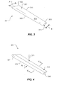
- Rotor 301 has a tip 303, a root 305, and an airfoil surface 307 disposed between tip 303 and root 305.
- Airfoil surface 307 has a leading edge 309 and a trailing edge 311.
- a suction surface 313 and a pressure surface 315 extend from leading edge 309 to trailing edge 311.
- Rotor 301 has two chord lengths A and B that extend linearly from leading edge 309 to trailing edge 311. Chord A is located at root 305 while chord B is located at tip 303. In the exemplary embodiment, chord A has a greater length than chord B and gradually decreases in length from root 305 to tip 303. Rotors are designed with various shapes, sizes and geometric contouring. For example, in alternative embodiments, the chord length could increase then decrease from root to tip. Considerable time and effort is invested in forming, grinding, polishing, and bonding the surface of the rotor through conventional methods for applying abrasion resistant materials. Additional time and effort is exhausted as the longitudinal length of the rotor increases and when the contouring becomes more complex.
- FIG. 4 an oblique view of rotor 301 is shown with an abrasion resistant material 401 that has been applied according to the preferred process of the present application.
- Abrasion resistant material 401 is applied to the leading edge 309, a portion of suction surface 313, and a portion of pressure surface 315.
- Two forces F1 and F2 illustrate forces acting against rotor 301 during flight.
- Force F1 depicts a force exerted against the surface of the rotor as the aircraft is propelled during flight.
- Rotors are composed of sufficiently flexible materials such as composites, metals, plastics, wood, and other suitable materials for counteracting force F1.
- the first coat of abrasion resistant material should be composed primarily of an elastomeric or similarly suited material for enabling the rotor to retain flexibility.
- the first coat has a composition of approximately 70 percent part per volume of an elastomeric material and approximately 30 percent part per volume of a metallic material. It should be understood that these percentages can vary in alternative embodiments.
- the first composition could be composed of approximately 90 percent elastomeric material and 10 percent metallic material.
- the abrasion resistant material is composed of an elastomeric material and a metallic material.
- the elastomeric material includes Teflon, polyimide, epoxy, or other suitable materials.
- the metallic material could include nickel, cobalt, or other suitable materials.
- the abrasion resistant material could be composed of one or more materials in addition to the elastomeric and metallic materials discussed.
- an alternative embodiment could include an abrasion resistant material composed of composite, plastic, and metallic materials.
- the first coat should be composed of a material suited for allowing the rotor to retain flexibility.
- Force F2 depicts the force exerted against leading edge 309 due to the bombardment of particulate matter during flight.
- the particulate matter gradually wears down the contoured shape of the leading edge.
- abrasion resistant material is applied to overcome the undesired wear.
- abrasion resistant material 401 is applied to leading edge 309, a portion of suction surface 313, and a portion of pressure surface 315 to a length up to 30 percent of the chord length, the chord length being measured from leading edge 309 to trailing edge 311.
- abrasion resistant material 401 could be applied to various portions of the rotor, including the entire surface area or solely to the suction or pressure surfaces.
- the abrasion resistant material is composed of both a metallic material and an elastomeric material.
- the elastomeric material provides means for allowing the rotor to retain flexibility, while the metallic material withstands wear from particulate matter.
- the second coat is composed of an abrasion resistant material having a metallic rich composition.
- the second coat is composed of approximately 5 percent part per volume of the elastomeric material and approximately 95 percent part per volume of the metallic material.
- the second composition could be composed of an abrasion resistant material having 30 percent part per volume of the elastomeric material and 70 percent part per volume of the metallic material.
- the second coat should be composed of a material that efficiently withstands wear from particulate matter.
- a coat is defined as a layer of abrasion resistant material having a different composition than the other layers of abrasion resistant material applied.
- a first coat is a layer of abrasion resistant material having a first composition
- a second coat is a layer of abrasion resistant material having a second composition, the second coat having a different composition than the first coat.
- Continuous application of multiple layers of abrasion resistant material that gradually transitions from a first composition to a second composition is considered to be comprised of multiple coats of abrasion resistant material. It should be appreciated that alternative embodiments could include solely a first and a second coat.
- a plurality of thin intermediary coats are disposed between the first and second coats.
- the intermediary coats are composed of both metallic and elastomeric materials. The intermediary coats gradually transition from an elastomeric rich to a metallic rich composition.
- FIG. 5 an enlarged longitudinal cross-sectional view of a section 501 of rotor 301 is shown taken at V-V of Figure 4 .
- Figure 5 illustrates cross-section 501 with abrasion resistant material 401 applied according to the preferred process of the present application.
- Abrasion resistant material 401 is applied to leading edge 309, a portion of suction surface 313, and a portion of pressure surface 315 with a spray coating system 503.
- System 503 includes a spray gun 505 having a nozzle 507 for directing spray 509 onto the surface of the rotor.
- Spray gun 505 is translatable in different directions with respect to rotor 301. As is shown, spray gun 505 can pivoted about arches C and D for spraying abrasion resistant materials onto surfaces 313 and 315, respectively. Spray gun 505 can also traverse down the longitudinal axis of rotor 301 for spraying the entire length of leading edge 309. In the preferred process, a larger sized nozzle 507 is used to produce larger diameter particles of spray 509 for creating a rough finish. A smaller sized nozzle 507 is used to produce finer particles of spray 509 for creating a smoother finish. Spray gun 505 can be configured to couple to an automative device 511 such as automative rail system or a robotic arm.
- an automative device 511 such as automative rail system or a robotic arm.
- Spray 509 is composed of a carrier gas and abrasion resistant material 401.
- the carrier gas includes a primary gas (Argon) and a secondary gas (Helium or Hydrogen).
- the carrier gas is heated to a temperature that sufficiently melts abrasion resistant material 401, but is not heated to a temperature that changes the microstructure or properties of the rotor during the application process.
- rotor 301 is composed of a material sufficiently flexible to withstand forces F1 and F2.
- the rotor is susceptible to deformation during the abrasion application process.
- the spray is applied at a temperature of less than 250 degrees Fahrenheit and with a Mach velocity ranging between Mach 1 and Mach 3.
- the splat size and density of the abrasion resistant material varies according to the nozzle size, temperature applied, and velocity propelled.
- the low temperature and high velocity provides sufficient thermal and kinetic energy for effectively bonding the abrasion resistant material to the surface of the rotor.
- FIG. 6 an enlarged cross-sectional view of a portion of section 501 is shown taken at VI-VI of Figure 5.
- Figure 6 illustrates abrasion resistant material 401 applied to pressure surface 315 according to the preferred process of the present application.
- abrasion resistant material 401 has a thickness T and includes three coatings 601, 603, and 605.
- abrasion resistant material 401 has a thickness T between .001 to .08 inches.
- spray coating system can be configured to apply coats with various thicknesses, thereby varying the overall thickness T of the abrasion resistant material. For example, in some applications a larger thickness of abrasion resistant material is desired at the tip of the rotor.
- System 503 can be configured to decrease the longitudinal speed near the tip while retaining the same feed rate of propelling spray 509, thereby increasing the thickness of each coat applied.
- first coat 603 is composed primary of an elastomeric material
- second coat 605 is composed primary of a metallic material
- intermediary coat 603 includes a plurality of layers disposed between first coat 601 and second coat 605.
- Each layer within intermediary coat 603 is composed of composition of abrasion resistant material that gradually transitions from an elastomeric rich material to a metallic rich material.
- coats 601, 603, and 605, as well as layers from coat 603 or other coats can be interposed by other layers and coats of other material as desired.
- material 401 can gradually transition from one composition to another rather than be composed of discrete coats and layers.
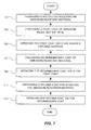
- Figure 7 a flow chart depicting the preferred process for applying abrasion resistant material according to the present application is illustrated.
- Figure 7 includes a number of interrelated steps for applying an abrasion resistant material to a rotor.
- Box 701 pertains to the process of preparing a rotor for receiving the abrasion resistant material.
- the surface of the rotor is cleaned and roughened to enhance adherence of subsequently applied abrasion resistant material.
- Cleaning techniques include mechanical abrasion such as through a vapor or air blast type process employing dry or liquid abrasion materials that impact the surface of the rotor.
- This step also includes the process of preparing the rotor for application of the abrasion resistant material either through a manual process or an automative process.
- the abrasion resistant material is applied in the field through a manual or automative process while the rotor remains attached to the aircraft.
- equipment used to apply the abrasion resistant materials i.e., powder feeder, compressor, gas supply, etc.
- the preferred process enables a worker to either manually apply abrasion resistant material to the rotor or to use an automative device to perform such features.
- the automative device is preprogrammed with the geometric dimensions of the rotor, feed rates for applying the abrasion resistant material, elastomeric to metallic ratios, and thicknesses for each coat.
- this step could include a process of detaching the rotor from the aircraft and coupling the rotor to a support structure. After the rotor is coupled to the support structure, the abrasion resistant material is applied either manually or through automative means, as described above. In this process, the support structure can be transported to the aircraft for field operations.
- Boxes 703 and 705 pertain to the process of preparing a first coat of abrasive material and spraying the first coat onto the surface of the rotor.
- the step of prepared the first coat is achieved by providing a hopper or similar device for storing and mixing the elastomeric and the metallic materials.
- the mixing process can be achieved by manually mixing the materials together or by mixing the materials through an automative process.
- a powder feeder is operably associated with the hopper for providing the desired elastomeric to metallic material ratios.
- the first coat is sprayed directly onto the surface of the rotor via spray system 503.
- Boxes 707 and 709 pertain to the process of preparing an intermediary coat of abrasive material and the process of spraying the intermediary coat onto the first coat.
- the intermediary coats are composed of both metallic and elastomeric materials and gradually transition from an elastomeric rich to a metallic rich composition.
- the elastomeric to metallic ratios are adjusted through an automative or manual process.
- Boxes 711 and 713 pertain to the process of preparing a second coat of an abrasion resistant material and spraying the second coat onto the intermediary coat.
- the second coat is the final coat applied.
- this coat is composed of an abrasion resistant material having a larger percentage part per volume of the metallic material.
- FIG. 8 a flow chart depicts an alternative process for applying abrasion resistant material to an abrasion strip.
- Figure 8 includes a number of interrelated steps for applying the abrasion resistant material to the abrasion strip. It should be understood that this process is substantially similar to the preferred process of applying abrasion resistant material to a rotor and that the preferred process can be applied to any suitable substrate.
- the wing of an aircraft experiences constant bombardment of particulate matter during flight, resulting in substantial wear.
- abrasion resistant material is applied to the wing according to the preferred process of the present application.
- box 801 pertains to an abrasion strip being prepared for abrasion resistant material.
- the surface of the abrasion strip is cleaned and roughened to enhance adherence of subsequently applied abrasion resistant material.
- Cleaning techniques include mechanical abrasion such as through a vapor or air blast type process employing dry or liquid abrasion materials that impact the surface of the abrasion strip.
- Boxes 803 and 805 pertain to the first coat being prepared and sprayed onto the surface of the abrasion strip.
- the first coat includes a composition composed of at least a first and a second material.
- the first coat is composed of a higher percentage part per volume of the first material than the percentage part per volume of the second material.
- the first material is an elastomeric material and the second material is a metallic material.
- the abrasion resistant material is applied in the field through a manual or automative process while the abrasion strip remains attached to the aircraft.
- equipment used to apply the abrasion resistant materials i.e., powder feeder, compressor, gas supply, etc.
- the preferred process enables a worker to either manually apply abrasion resistant material to the abrasion strip or to use an automative device to perform such features.
- the automative device is preprogrammed with the geometric dimensions of the abrasion strip, feed rates for applying the abrasion resistant material, elastomeric to metallic ratios, and thicknesses for each coat.
- this step could include a process of detaching the abrasion strip from the aircraft and coupling the abrasion strip to a support structure. After the abrasion strip is coupled to the support structure, the abrasion resistant material is applied either manually or through automative means, as described above. In this process, the support structure can be transported to the aircraft for field operations.
- Boxes 807 and 809 pertain to the process of preparing and spraying an intermediary coat onto the first coat.
- the intermediary coats are composed of both metallic and elastomeric materials and gradually transition from an elastomeric rich to a metallic rich composition.
- the elastomeric to metallic ratios are adjusted through an automative or manual process.
- Boxes 811 and 813 pertain to the second coat being prepared and sprayed onto the surface of the first coat.
- the second coat is the final coat applied.
- the second coat is composed of an abrasion resistant material having a larger percentage part per volume of the second material.
- the process of the present application provides significant advantages, including: (1) handling and shipping costs are reduced; (2) substantial time and effort is no longer exhausted through the upgrading process; (3) different coatings are applied without having to change any forming or cutting tooling; and (4) the worker can perform the application process in the field.
Landscapes
- Engineering & Computer Science (AREA)
- Chemical & Material Sciences (AREA)
- Mechanical Engineering (AREA)
- Materials Engineering (AREA)
- General Engineering & Computer Science (AREA)
- Physics & Mathematics (AREA)
- Plasma & Fusion (AREA)
- Chemical Kinetics & Catalysis (AREA)
- Metallurgy (AREA)
- Organic Chemistry (AREA)
- Coating By Spraying Or Casting (AREA)
- Application Of Or Painting With Fluid Materials (AREA)
Description
- The present application relates generally to the field of abrasion resistant materials and, more particularly, to a process for applying abrasion resistant materials to a substrate.
- Rotors are well known in the art for effectively propelling various types of aircraft in flight. For example,
Figure 1 illustrates aconventional tiltrotor aircraft 101 propelled by tworotors Figure 2 illustrates aconventional helicopter 201 propelled byrotor 203. Rotors come in various shapes, sizes and with different aerodynamic contouring for providing maximum propulsion. As is shown,rotors rotor 203. Like the majority of rotors,rotors - Abrasion resistant materials are applied to the rotors for overcoming the undesired wear. Abrasion resistant materials help to maintain the original design of the rotor by withstanding mechanical action such as rubbing, scraping, or erosion that tends to progressively remove material from the surface. There exist various methods for applying abrasion resistant materials to a substrate. For example,
U.S. Patent No. 4,802,828 to Rutz et al. suggests several techniques for providing an abrasion resistant layer to a substrate, including powder metallurgy techniques, plasma spray techniques, and electroplating techniques. In addition, alternative techniques include mechanical shields and electroforming. - In
WO2006/055038 , a method of protecting a substrate against damage is described. The method comprising disposing on a substrate one or more coatings, wherein one coating comprises an isocyanate-terminated polyurethane prepolymer and a curing agent; wherein the curing agents comprise polyaspartic esters, ketimines, aldimines, or a combination comprising at least one of the foregoing curing agents; reacting the isocyanate-terminated polyurethane prepolymer with a curing agent; wherein the reacting can optionally be carried out in the presence of moisture or heat; and curing the isoycyanate-terminated polyurethane prepolymer to form the coating. - In
WO2007/075497 , the repair and removal of erosion or impact damage to a curved substrate are described, wherein hand sandable elastomeric coatings are applied to a curved substrate, particularly surfaces such as the leading edge of an airfoil. - In
GB 2115499 - Mechanical shields include tape, wood, metal or other similarly suited materials configured for fitting on the contoured surface of the rotor. The shields are securely screwed or adhesively bonded to the exposed surface. The shields provide an inexpensive solution for adding additional abrasion and erosion resistance, but have been found to be ineffective as a means for reducing wear.
- Electroplating is a process that uses a chemical bath to plate the surface area of the rotor with an abrasion resistant material. This process includes placing the rotor within a sufficiently sized bath and applying an electric current to the bath for depositing an abrasion resistant material on the surface area of the rotor. The coating thickness of the abrasion resistant material is not uniform, resulting in considerable post-process upgrade work, such as grinding to make the rotor aerodynamically satisfactory. There is also a need to ship the rotors to the plating facility, as plating lines cannot be moved to where the aircraft is located. As a result, disassembly, handling, and shipping costs accrue.
- Electroforming is a process that uses an electrodeposition in a plating bath over a base form or mandrel which is subsequently removed. Technically, it is a process of synthesizing a metal object by controlling the electrodeposition of metal passing through an electrolytic solution onto a metal or metallized form. More simply, a metal skin is built up on a metal surface, or any surface that has been rendered electroconductive through the application of a paint that contains metal particles. Essentially, a metal part is fabricated from the plating itself. This process differs from electroplating because the skin is much thicker and can exist as a self-supporting structure if the original matrix, or mandrel, is removed. Like the electroplating process, electroforming requires a large bath sufficiently sized for a rotor and considerable post-process upgrade work is performed. In addition, the rotors must be shipped to the facility, resulting in disassembly, handling, and shipping costs. In both cases, there is a considerable effort and time invested in forming, grinding, polishing, and bonding in order to arrive at the finished product. Both electroplating and electroforming process are slow, difficult to control, complex in nature, and limited with regard to suppliers of services and raw materials.
- Plasma spraying devices and techniques are also well known in the art for depositing protective coating on underlying substrates. One known device is illustrated in
U.S. Patent No. 3,145,287 to Siebein et al entitled "Plasma Flame Generator and Spray Gun." In accordance with the teachings of Siebein et al, a plasma-forming gas forms a sheath around an electric arc. The sheath of gases constricts and extends the arc part way down the nozzle. The gas is converted to a plasma state and leaves the arc and nozzle as a hot plasma stream. Powders are injected into the hot plasma stream and propelled onto the surface of the substrate to be coated. - Although the foregoing developments represent great strides in the area of applying abrasion resistant materials to rotors, many shortcomings remain.
- The invention provides a process for applying an abrasion resistant material to a rotor of an aircraft according to claim 1. The novel features characteristic of the invention are set forth in the appended claims. However, the application itself, as well as, a preferred mode of use, and further objectives and advantages thereof, will best be understood by reference to the following detailed description when read in conjunction with the accompanying drawings, wherein:
-
Figure 1 is an oblique view of a conventional tiltrotor aircraft; -
Figure 2 is a side view of a conventional helicopter; -
Figure 3 is an oblique view of a rotor; -
Figure 4 is an oblique view of the rotor ofFigure 3 with an abrasion resistant material applied according to the preferred process of the present application; -
Figure 5 is an enlarged longitudinal cross-sectional view of the rotor ofFigure 4 taken at V-V inFigure 4 ; -
Figure 6 is an enlarged cross-sectional view of a portion of the rotor ofFigure 5 taken at VI-VI inFigure 5 ; -
Figure 7 is a flow chart illustrating the process of applying an abrasion resistant material to a rotor according to preferred process of the present application; and -
Figure 8 is a flow chart illustrating the process of applying an abrasion resistant material to an abrasion strip according to preferred process of the present application. - While the process of the present application is susceptible to various modifications and alternative forms, specific embodiments thereof have been shown by way of example in the drawings and are herein described in detail.
- The process for applying an abrasion resistant material to a rotor according to claim 1, overcomes the disadvantages of conventional techniques for applying abrasion resistant materials to rotors. Illustrative embodiments are described below. It will of course be appreciated that in the development of any actual embodiment, numerous implementation-specific decisions will be made to achieve the developer's specific goals, such as compliance with system-related and business-related constraints, which will vary from one implementation to another. Moreover, it will be appreciated that such a development effort might be complex and time-consuming, but would nevertheless be a routine undertaking for those of ordinary skill in the art having the benefit of this disclosure.
- The present application is directed to a process for applying abrasion resistant materials to a rotor according to claim 1. The abrasion resistant material is thermally sprayed onto the rotor either through a manual or by an automated process. The process can be performed in the field or within a facility. The abrasion resistant material is composed of a mixed composition comprising a first and a second material. In the preferred embodiment, the first material is an elastomeric material, while the second material is a metallic material. A plurality of abrasion resistant coats are applied to the surface of the rotor. The coats gradually transition from an elastomeric rich material to a metallic rich material as additional coats are applied.
- Referring now to
Figure 3 in the drawings, an oblique view of arotor 301 is shown.Rotor 301 has atip 303, aroot 305, and anairfoil surface 307 disposed betweentip 303 androot 305.Airfoil surface 307 has aleading edge 309 and a trailingedge 311. Asuction surface 313 and apressure surface 315 extend from leadingedge 309 to trailingedge 311. -
Rotor 301 has two chord lengths A and B that extend linearly from leadingedge 309 to trailingedge 311. Chord A is located atroot 305 while chord B is located attip 303. In the exemplary embodiment, chord A has a greater length than chord B and gradually decreases in length fromroot 305 totip 303. Rotors are designed with various shapes, sizes and geometric contouring. For example, in alternative embodiments, the chord length could increase then decrease from root to tip. Considerable time and effort is invested in forming, grinding, polishing, and bonding the surface of the rotor through conventional methods for applying abrasion resistant materials. Additional time and effort is exhausted as the longitudinal length of the rotor increases and when the contouring becomes more complex. - Referring now to
Figure 4 in the drawings, an oblique view ofrotor 301 is shown with an abrasionresistant material 401 that has been applied according to the preferred process of the present application. Abrasionresistant material 401 is applied to theleading edge 309, a portion ofsuction surface 313, and a portion ofpressure surface 315. Two forces F1 and F2 illustrate forces acting againstrotor 301 during flight. - Force F1 depicts a force exerted against the surface of the rotor as the aircraft is propelled during flight. Rotors are composed of sufficiently flexible materials such as composites, metals, plastics, wood, and other suitable materials for counteracting force F1. To retain such flexibility, it is found that the first coat of abrasion resistant material should be composed primarily of an elastomeric or similarly suited material for enabling the rotor to retain flexibility. In the preferred embodiment, the first coat has a composition of approximately 70 percent part per volume of an elastomeric material and approximately 30 percent part per volume of a metallic material. It should be understood that these percentages can vary in alternative embodiments. For example, the first composition could be composed of approximately 90 percent elastomeric material and 10 percent metallic material.
- In the preferred embodiment, the abrasion resistant material is composed of an elastomeric material and a metallic material. The elastomeric material includes Teflon, polyimide, epoxy, or other suitable materials. The metallic material could include nickel, cobalt, or other suitable materials. In alternative embodiments, the abrasion resistant material could be composed of one or more materials in addition to the elastomeric and metallic materials discussed. For example, an alternative embodiment could include an abrasion resistant material composed of composite, plastic, and metallic materials. Despite the materials used, the first coat should be composed of a material suited for allowing the rotor to retain flexibility.
- Force F2 depicts the force exerted against
leading edge 309 due to the bombardment of particulate matter during flight. The particulate matter gradually wears down the contoured shape of the leading edge. As such, abrasion resistant material is applied to overcome the undesired wear. In the preferred embodiment, abrasionresistant material 401 is applied to leadingedge 309, a portion ofsuction surface 313, and a portion ofpressure surface 315 to a length up to 30 percent of the chord length, the chord length being measured from leadingedge 309 to trailingedge 311. In alternative embodiments, abrasionresistant material 401 could be applied to various portions of the rotor, including the entire surface area or solely to the suction or pressure surfaces. - In the preferred embodiment, the abrasion resistant material is composed of both a metallic material and an elastomeric material. The elastomeric material provides means for allowing the rotor to retain flexibility, while the metallic material withstands wear from particulate matter. Thus, in the preferred embodiment the second coat is composed of an abrasion resistant material having a metallic rich composition. The second coat is composed of approximately 5 percent part per volume of the elastomeric material and approximately 95 percent part per volume of the metallic material. However, it should be understood that these percentages can change in alternative embodiments. For example, the second composition could be composed of an abrasion resistant material having 30 percent part per volume of the elastomeric material and 70 percent part per volume of the metallic material. Despite the elastomeric to metallic ratio used, the second coat should be composed of a material that efficiently withstands wear from particulate matter.
- In the preferred embodiment, multiple coats of abrasion resistant material are applied to the rotor. It should be understood that for the purpose of this application, a coat is defined as a layer of abrasion resistant material having a different composition than the other layers of abrasion resistant material applied. For example, a first coat is a layer of abrasion resistant material having a first composition and a second coat is a layer of abrasion resistant material having a second composition, the second coat having a different composition than the first coat. Continuous application of multiple layers of abrasion resistant material that gradually transitions from a first composition to a second composition is considered to be comprised of multiple coats of abrasion resistant material. It should be appreciated that alternative embodiments could include solely a first and a second coat. In the preferred embodiment, a plurality of thin intermediary coats are disposed between the first and second coats. Like the first and second coats, the intermediary coats are composed of both metallic and elastomeric materials. The intermediary coats gradually transition from an elastomeric rich to a metallic rich composition.
- Referring now to
Figure 5 in the drawings, an enlarged longitudinal cross-sectional view of asection 501 ofrotor 301 is shown taken at V-V ofFigure 4 .Figure 5 illustratescross-section 501 with abrasionresistant material 401 applied according to the preferred process of the present application. Abrasionresistant material 401 is applied to leadingedge 309, a portion ofsuction surface 313, and a portion ofpressure surface 315 with aspray coating system 503.System 503 includes aspray gun 505 having anozzle 507 for directingspray 509 onto the surface of the rotor. -
Spray gun 505 is translatable in different directions with respect torotor 301. As is shown,spray gun 505 can pivoted about arches C and D for spraying abrasion resistant materials ontosurfaces Spray gun 505 can also traverse down the longitudinal axis ofrotor 301 for spraying the entire length of leadingedge 309. In the preferred process, a largersized nozzle 507 is used to produce larger diameter particles ofspray 509 for creating a rough finish. A smallersized nozzle 507 is used to produce finer particles ofspray 509 for creating a smoother finish.Spray gun 505 can be configured to couple to anautomative device 511 such as automative rail system or a robotic arm. -
Spray 509 is composed of a carrier gas and abrasionresistant material 401. In the preferred embodiment, the carrier gas includes a primary gas (Argon) and a secondary gas (Helium or Hydrogen). The carrier gas is heated to a temperature that sufficiently melts abrasionresistant material 401, but is not heated to a temperature that changes the microstructure or properties of the rotor during the application process. As discussed,rotor 301 is composed of a material sufficiently flexible to withstand forces F1 and F2. The rotor is susceptible to deformation during the abrasion application process. In the preferred embodiment, the spray is applied at a temperature of less than 250 degrees Fahrenheit and with a Mach velocity ranging between Mach 1 and Mach 3. The splat size and density of the abrasion resistant material varies according to the nozzle size, temperature applied, and velocity propelled. The low temperature and high velocity provides sufficient thermal and kinetic energy for effectively bonding the abrasion resistant material to the surface of the rotor. - Referring now to
Figure 6 in the drawings, an enlarged cross-sectional view of a portion ofsection 501 is shown taken at VI-VI ofFigure 5. Figure 6 illustrates abrasionresistant material 401 applied topressure surface 315 according to the preferred process of the present application. As is shown, abrasionresistant material 401 has a thickness T and includes threecoatings - In the preferred embodiment, abrasion
resistant material 401 has a thickness T between .001 to .08 inches. It should be appreciated that spray coating system can be configured to apply coats with various thicknesses, thereby varying the overall thickness T of the abrasion resistant material. For example, in some applications a larger thickness of abrasion resistant material is desired at the tip of the rotor.System 503 can be configured to decrease the longitudinal speed near the tip while retaining the same feed rate of propellingspray 509, thereby increasing the thickness of each coat applied. - As discussed,
first coat 603 is composed primary of an elastomeric material, whilesecond coat 605 is composed primary of a metallic material. In the preferred embodiment,intermediary coat 603 includes a plurality of layers disposed betweenfirst coat 601 andsecond coat 605. Each layer withinintermediary coat 603 is composed of composition of abrasion resistant material that gradually transitions from an elastomeric rich material to a metallic rich material. In some embodiments,coats coat 603 or other coats, can be interposed by other layers and coats of other material as desired. Also, in some embodiments,material 401 can gradually transition from one composition to another rather than be composed of discrete coats and layers. - Referring now to
Figure 7 in the drawings, a flow chart depicting the preferred process for applying abrasion resistant material according to the present application is illustrated.Figure 7 includes a number of interrelated steps for applying an abrasion resistant material to a rotor. -
Box 701 pertains to the process of preparing a rotor for receiving the abrasion resistant material. In this step, the surface of the rotor is cleaned and roughened to enhance adherence of subsequently applied abrasion resistant material. Cleaning techniques include mechanical abrasion such as through a vapor or air blast type process employing dry or liquid abrasion materials that impact the surface of the rotor. This step also includes the process of preparing the rotor for application of the abrasion resistant material either through a manual process or an automative process. - In the preferred embodiment, the abrasion resistant material is applied in the field through a manual or automative process while the rotor remains attached to the aircraft. To perform field operations, equipment used to apply the abrasion resistant materials, i.e., powder feeder, compressor, gas supply, etc., is transported to the aircraft via truck or by other suitable vehicles. The preferred process enables a worker to either manually apply abrasion resistant material to the rotor or to use an automative device to perform such features. In the preferred embodiment, the automative device is preprogrammed with the geometric dimensions of the rotor, feed rates for applying the abrasion resistant material, elastomeric to metallic ratios, and thicknesses for each coat.
- It should be appreciated that alternative embodiments of this step could include a process of detaching the rotor from the aircraft and coupling the rotor to a support structure. After the rotor is coupled to the support structure, the abrasion resistant material is applied either manually or through automative means, as described above. In this process, the support structure can be transported to the aircraft for field operations.
-
Boxes spray system 503. -
Boxes -
Boxes 711 and 713 pertain to the process of preparing a second coat of an abrasion resistant material and spraying the second coat onto the intermediary coat. The second coat is the final coat applied. As discussed, this coat is composed of an abrasion resistant material having a larger percentage part per volume of the metallic material. - Referring now to
Figure 8 in the drawings, a flow chart depicts an alternative process for applying abrasion resistant material to an abrasion strip.Figure 8 includes a number of interrelated steps for applying the abrasion resistant material to the abrasion strip. It should be understood that this process is substantially similar to the preferred process of applying abrasion resistant material to a rotor and that the preferred process can be applied to any suitable substrate. For example, the wing of an aircraft experiences constant bombardment of particulate matter during flight, resulting in substantial wear. To overcome the abrasion wear, abrasion resistant material is applied to the wing according to the preferred process of the present application. - In
Figure 8 ,box 801 pertains to an abrasion strip being prepared for abrasion resistant material. In this step, the surface of the abrasion strip is cleaned and roughened to enhance adherence of subsequently applied abrasion resistant material. Cleaning techniques include mechanical abrasion such as through a vapor or air blast type process employing dry or liquid abrasion materials that impact the surface of the abrasion strip. -
Boxes - In the preferred embodiment, the abrasion resistant material is applied in the field through a manual or automative process while the abrasion strip remains attached to the aircraft. To perform field operations, equipment used to apply the abrasion resistant materials, i.e., powder feeder, compressor, gas supply, etc., is transported to the aircraft via truck or by other suitable vehicles. The preferred process enables a worker to either manually apply abrasion resistant material to the abrasion strip or to use an automative device to perform such features. In the preferred embodiment, the automative device is preprogrammed with the geometric dimensions of the abrasion strip, feed rates for applying the abrasion resistant material, elastomeric to metallic ratios, and thicknesses for each coat.
- It should be appreciated that alternative embodiments of this step could include a process of detaching the abrasion strip from the aircraft and coupling the abrasion strip to a support structure. After the abrasion strip is coupled to the support structure, the abrasion resistant material is applied either manually or through automative means, as described above. In this process, the support structure can be transported to the aircraft for field operations.
-
Boxes -
Boxes - The process of the present application provides significant advantages, including: (1) handling and shipping costs are reduced; (2) substantial time and effort is no longer exhausted through the upgrading process; (3) different coatings are applied without having to change any forming or cutting tooling; and (4) the worker can perform the application process in the field.
Claims (9)
- A process for applying an abrasion resistant material to a rotor of an aircraft, the rotor having a tip, a root, a leading edge, a trailing edge, a surface disposed between the tip and the root, and a chord length extending linearly from the leading edge to the trailing edge, the process comprising:preparing the surface of the rotor for receiving the abrasion resistant material;preparing a first coat of the abrasion resistant material, the first coat being composed of an elastomeric abrasion resistant material;spraying the first coat onto the surface of the rotor;preparing an intermediary coat being composed of the elastomeric abrasion resistant material and a metallic abrasion resistant material;spraying the intermediary coat on the first coat;preparing a second coat of the abrasion resistant material, the second coat being composed of a metallic abrasion resistant material; andspraying the second coat onto the intermediary coat; characterised in that the intermediary coat includes a plurality of abrasion resistant layers that transition from a smaller percentage part per volume of the elastomeric material to a larger percentage part per volume of the metallic material.
- The process according to claim 1, wherein the first coat is composed of an abrasion resistant material having a 70 percent part per volume of the elastomeric material and a 30 percent part per volume of the metallic material.
- The process according to claim 1, wherein the second coat is composed of an abrasion resistant material having a 5 percent part per volume of the elastomeric material and a 95 percent part per volume of the metallic material.
- The process according to claim 1, further comprising:applying the abrasion resistant material to the rotor while the rotor remains coupled to the aircraft.
- The process according to claim 1, further comprising:removing the rotor from the aircraft; andcoupling the rotor to a support structure.
- The process according to claim 1, wherein the spraying of the first coat onto the surface of the rotor is achieved by providing a coating system having a plasma spray gun.
- The process according to claim 6, wherein the coating system is operably associated with an automative device for propelling abrasion resistant material onto the surface of the rotor.
- The process according to claim 6, wherein the coating system is configured for manually applying abrasion resistant material onto the surface of the rotor.
- The process according to claim 1, wherein the first coat is sprayed onto the surface area of the rotor to a distance up to about 30 percent of the chord length, the chord length being measured from the leading edge to the trailing edge of the rotor.
Applications Claiming Priority (1)
| Application Number | Priority Date | Filing Date | Title |
|---|---|---|---|
| PCT/US2009/050827 WO2011008211A1 (en) | 2009-07-16 | 2009-07-16 | Method of applying abrasion resistant materials to rotors |
Publications (3)
| Publication Number | Publication Date |
|---|---|
| EP2454470A1 EP2454470A1 (en) | 2012-05-23 |
| EP2454470A4 EP2454470A4 (en) | 2012-06-27 |
| EP2454470B1 true EP2454470B1 (en) | 2015-05-27 |
Family
ID=43449627
Family Applications (1)
| Application Number | Title | Priority Date | Filing Date |
|---|---|---|---|
| EP09847438.0A Active EP2454470B1 (en) | 2009-07-16 | 2009-07-16 | Method of applying abrasion resistant materials to rotors |
Country Status (5)
| Country | Link |
|---|---|
| US (1) | US20120096714A1 (en) |
| EP (1) | EP2454470B1 (en) |
| CN (1) | CN102472242B (en) |
| CA (1) | CA2767795C (en) |
| WO (1) | WO2011008211A1 (en) |
Cited By (1)
| Publication number | Priority date | Publication date | Assignee | Title |
|---|---|---|---|---|
| EP4282633A1 (en) * | 2022-05-18 | 2023-11-29 | RTX Corporation | Fan blade repair systems and methods |
Families Citing this family (6)
| Publication number | Priority date | Publication date | Assignee | Title |
|---|---|---|---|---|
| US7736745B2 (en) | 2004-05-24 | 2010-06-15 | Hontek Corporation | Abrasion resistant coatings |
| US20120163981A1 (en) * | 2010-12-22 | 2012-06-28 | Hong Shek C | Method and coating for protecting and repairing an airfoil surface |
| US9598973B2 (en) | 2012-11-28 | 2017-03-21 | General Electric Company | Seal systems for use in turbomachines and methods of fabricating the same |
| US10017844B2 (en) | 2015-12-18 | 2018-07-10 | General Electric Company | Coated articles and method for making |
| US10815797B2 (en) * | 2016-08-12 | 2020-10-27 | Hamilton Sundstrand Corporation | Airfoil systems and methods of assembly |
| US11629603B2 (en) | 2020-03-31 | 2023-04-18 | General Electric Company | Turbomachine airfoil having a variable thickness thermal barrier coating |
Family Cites Families (15)
| Publication number | Priority date | Publication date | Assignee | Title |
|---|---|---|---|---|
| US4334495A (en) * | 1978-07-11 | 1982-06-15 | Trw Inc. | Method and apparatus for use in making an object |
| US4451205A (en) * | 1982-02-22 | 1984-05-29 | United Technologies Corporation | Rotor blade assembly |
| US5743494A (en) * | 1995-03-07 | 1998-04-28 | The Bfgoodrich Company | Polyurethane deicer |
| US6284390B1 (en) * | 1998-06-12 | 2001-09-04 | United Technologies Corporation | Thermal barrier coating system utilizing localized bond coat and article having the same |
| US6341747B1 (en) * | 1999-10-28 | 2002-01-29 | United Technologies Corporation | Nanocomposite layered airfoil |
| SG96589A1 (en) * | 1999-12-20 | 2003-06-16 | United Technologies Corp | Methods of providing article with corrosion resistant coating and coated article |
| US6319560B1 (en) * | 2000-03-29 | 2001-11-20 | Sulzer Metco (Us) Inc. | Apparatus and method for coating the outer surface of a workpiece |
| AUPR373901A0 (en) * | 2001-03-14 | 2001-04-12 | Leach Aero Services Pty Ltd | An article having an erodynamic surface |
| US6780458B2 (en) * | 2001-08-01 | 2004-08-24 | Siemens Westinghouse Power Corporation | Wear and erosion resistant alloys applied by cold spray technique |
| JP3886394B2 (en) * | 2002-02-25 | 2007-02-28 | 株式会社荏原製作所 | Covering material with corrosion resistance and wear resistance |
| US20040118978A1 (en) * | 2002-12-24 | 2004-06-24 | Anning Bruce D. | Helicopter rotor and method of repairing same |
| US7736745B2 (en) * | 2004-05-24 | 2010-06-15 | Hontek Corporation | Abrasion resistant coatings |
| FR2884550B1 (en) * | 2005-04-15 | 2010-09-17 | Snecma Moteurs | PIECE FOR PROTECTING THE EDGE OF A BLADE |
| CN1962926A (en) * | 2005-11-08 | 2007-05-16 | 中国科学院金属研究所 | Metal materials protection method (2) |
| EP1989005B1 (en) * | 2005-12-14 | 2017-09-20 | Hontek Corporation | Method and coating for protecting and repairing an airfoil surface |
-
2009
- 2009-07-16 EP EP09847438.0A patent/EP2454470B1/en active Active
- 2009-07-16 CA CA2767795A patent/CA2767795C/en active Active
- 2009-07-16 CN CN200980160474.XA patent/CN102472242B/en not_active Expired - Fee Related
- 2009-07-16 US US13/380,880 patent/US20120096714A1/en not_active Abandoned
- 2009-07-16 WO PCT/US2009/050827 patent/WO2011008211A1/en not_active Ceased
Cited By (1)
| Publication number | Priority date | Publication date | Assignee | Title |
|---|---|---|---|---|
| EP4282633A1 (en) * | 2022-05-18 | 2023-11-29 | RTX Corporation | Fan blade repair systems and methods |
Also Published As
| Publication number | Publication date |
|---|---|
| CA2767795A1 (en) | 2011-01-20 |
| EP2454470A1 (en) | 2012-05-23 |
| WO2011008211A1 (en) | 2011-01-20 |
| CA2767795C (en) | 2016-04-12 |
| CN102472242B (en) | 2016-09-07 |
| CN102472242A (en) | 2012-05-23 |
| US20120096714A1 (en) | 2012-04-26 |
| EP2454470A4 (en) | 2012-06-27 |
Similar Documents
| Publication | Publication Date | Title |
|---|---|---|
| CA2767795C (en) | Method of applying abrasion resistant materials to rotors | |
| RU2616707C2 (en) | Method of security reinforcement for front edge of blade | |
| US6955308B2 (en) | Process of selectively removing layers of a thermal barrier coating system | |
| CN102560481B (en) | Two-layer structure coating is used to manufacture the method for component | |
| EP3019711B1 (en) | Plated polymer nosecone | |
| US20120114868A1 (en) | Method of fabricating a component using a fugitive coating | |
| EP2327812A1 (en) | Near net shape composite airfoil leading edge protective strips made using cold spray deposition | |
| EP2823085B1 (en) | Method of making leading edge protection | |
| US20100008788A1 (en) | Protector for a leading edge of an airfoil | |
| US20170144270A1 (en) | Method for producing a corrosion-inhibiting or adhesion-promoting coating | |
| US20110129600A1 (en) | Cold spray deposition processes for making near net shape composite airfoil leading edge protective strips and composite airfoils comprising the same | |
| JPH10502714A (en) | Erosion resistant surface protection | |
| EP2576138B2 (en) | Method for removal of ceramic coatings by solid co² blasting | |
| US20120163981A1 (en) | Method and coating for protecting and repairing an airfoil surface | |
| EP2914489B1 (en) | A porous coating applied onto an aerial article | |
| US20150111058A1 (en) | Method of coating a composite material and a coated edge of a composite structure | |
| US3892883A (en) | Process for plasma spraying fiber-reinforced thermosetting resin laminates | |
| EP3266607B1 (en) | Fiber-reinforced resin structure and method for producing fiber-reinforced resin structure | |
| US12516419B2 (en) | Leading-edge structures for airfoils and systems and methods for fabricating the same | |
| CN103818053B (en) | In-mold metallization of composite structures | |
| Robitaille et al. | Production of metallic coatings on polymer-matrix composites | |
| Archambault | Lay-up Moulding of a Carbon Fiber Reinforced Polymer Composite on a Cold Sprayed Metallic Layer | |
| Cormier | Repair of Conductive Layer on Carbon Fibre Reinforced Polymer Composite with Cold Gas Dynamic Spray |
Legal Events
| Date | Code | Title | Description |
|---|---|---|---|
| PUAI | Public reference made under article 153(3) epc to a published international application that has entered the european phase |
Free format text: ORIGINAL CODE: 0009012 |
|
| REG | Reference to a national code |
Ref country code: DE Ref legal event code: R079 Ref document number: 602009031501 Country of ref document: DE Free format text: PREVIOUS MAIN CLASS: F03B0003120000 Ipc: F01D0005000000 |
|
| 17P | Request for examination filed |
Effective date: 20120103 |
|
| AK | Designated contracting states |
Kind code of ref document: A1 Designated state(s): AT BE BG CH CY CZ DE DK EE ES FI FR GB GR HR HU IE IS IT LI LT LU LV MC MK MT NL NO PL PT RO SE SI SK SM TR |
|
| A4 | Supplementary search report drawn up and despatched |
Effective date: 20120529 |
|
| RIC1 | Information provided on ipc code assigned before grant |
Ipc: F01D 5/00 20060101AFI20120522BHEP Ipc: C23C 4/02 20060101ALI20120522BHEP Ipc: F01D 5/28 20060101ALI20120522BHEP |
|
| DAX | Request for extension of the european patent (deleted) | ||
| 17Q | First examination report despatched |
Effective date: 20140915 |
|
| GRAP | Despatch of communication of intention to grant a patent |
Free format text: ORIGINAL CODE: EPIDOSNIGR1 |
|
| GRAS | Grant fee paid |
Free format text: ORIGINAL CODE: EPIDOSNIGR3 |
|
| INTG | Intention to grant announced |
Effective date: 20150323 |
|
| GRAA | (expected) grant |
Free format text: ORIGINAL CODE: 0009210 |
|
| AK | Designated contracting states |
Kind code of ref document: B1 Designated state(s): AT BE BG CH CY CZ DE DK EE ES FI FR GB GR HR HU IE IS IT LI LT LU LV MC MK MT NL NO PL PT RO SE SI SK SM TR |
|
| REG | Reference to a national code |
Ref country code: GB Ref legal event code: FG4D |
|
| REG | Reference to a national code |
Ref country code: CH Ref legal event code: EP |
|
| REG | Reference to a national code |
Ref country code: AT Ref legal event code: REF Ref document number: 728979 Country of ref document: AT Kind code of ref document: T Effective date: 20150615 |
|
| REG | Reference to a national code |
Ref country code: IE Ref legal event code: FG4D |
|
| REG | Reference to a national code |
Ref country code: DE Ref legal event code: R096 Ref document number: 602009031501 Country of ref document: DE |
|
| REG | Reference to a national code |
Ref country code: AT Ref legal event code: MK05 Ref document number: 728979 Country of ref document: AT Kind code of ref document: T Effective date: 20150527 |
|
| REG | Reference to a national code |
Ref country code: LT Ref legal event code: MG4D |
|
| PG25 | Lapsed in a contracting state [announced via postgrant information from national office to epo] |
Ref country code: LT Free format text: LAPSE BECAUSE OF FAILURE TO SUBMIT A TRANSLATION OF THE DESCRIPTION OR TO PAY THE FEE WITHIN THE PRESCRIBED TIME-LIMIT Effective date: 20150527 Ref country code: FI Free format text: LAPSE BECAUSE OF FAILURE TO SUBMIT A TRANSLATION OF THE DESCRIPTION OR TO PAY THE FEE WITHIN THE PRESCRIBED TIME-LIMIT Effective date: 20150527 Ref country code: NO Free format text: LAPSE BECAUSE OF FAILURE TO SUBMIT A TRANSLATION OF THE DESCRIPTION OR TO PAY THE FEE WITHIN THE PRESCRIBED TIME-LIMIT Effective date: 20150827 Ref country code: ES Free format text: LAPSE BECAUSE OF FAILURE TO SUBMIT A TRANSLATION OF THE DESCRIPTION OR TO PAY THE FEE WITHIN THE PRESCRIBED TIME-LIMIT Effective date: 20150527 Ref country code: HR Free format text: LAPSE BECAUSE OF FAILURE TO SUBMIT A TRANSLATION OF THE DESCRIPTION OR TO PAY THE FEE WITHIN THE PRESCRIBED TIME-LIMIT Effective date: 20150527 Ref country code: PT Free format text: LAPSE BECAUSE OF FAILURE TO SUBMIT A TRANSLATION OF THE DESCRIPTION OR TO PAY THE FEE WITHIN THE PRESCRIBED TIME-LIMIT Effective date: 20150928 |
|
| REG | Reference to a national code |
Ref country code: NL Ref legal event code: MP Effective date: 20150527 |
|
| PG25 | Lapsed in a contracting state [announced via postgrant information from national office to epo] |
Ref country code: LV Free format text: LAPSE BECAUSE OF FAILURE TO SUBMIT A TRANSLATION OF THE DESCRIPTION OR TO PAY THE FEE WITHIN THE PRESCRIBED TIME-LIMIT Effective date: 20150527 Ref country code: AT Free format text: LAPSE BECAUSE OF FAILURE TO SUBMIT A TRANSLATION OF THE DESCRIPTION OR TO PAY THE FEE WITHIN THE PRESCRIBED TIME-LIMIT Effective date: 20150527 Ref country code: IS Free format text: LAPSE BECAUSE OF FAILURE TO SUBMIT A TRANSLATION OF THE DESCRIPTION OR TO PAY THE FEE WITHIN THE PRESCRIBED TIME-LIMIT Effective date: 20150927 Ref country code: BG Free format text: LAPSE BECAUSE OF FAILURE TO SUBMIT A TRANSLATION OF THE DESCRIPTION OR TO PAY THE FEE WITHIN THE PRESCRIBED TIME-LIMIT Effective date: 20150827 Ref country code: GR Free format text: LAPSE BECAUSE OF FAILURE TO SUBMIT A TRANSLATION OF THE DESCRIPTION OR TO PAY THE FEE WITHIN THE PRESCRIBED TIME-LIMIT Effective date: 20150828 |
|
| PG25 | Lapsed in a contracting state [announced via postgrant information from national office to epo] |
Ref country code: EE Free format text: LAPSE BECAUSE OF FAILURE TO SUBMIT A TRANSLATION OF THE DESCRIPTION OR TO PAY THE FEE WITHIN THE PRESCRIBED TIME-LIMIT Effective date: 20150527 Ref country code: DK Free format text: LAPSE BECAUSE OF FAILURE TO SUBMIT A TRANSLATION OF THE DESCRIPTION OR TO PAY THE FEE WITHIN THE PRESCRIBED TIME-LIMIT Effective date: 20150527 |
|
| PG25 | Lapsed in a contracting state [announced via postgrant information from national office to epo] |
Ref country code: RO Free format text: LAPSE BECAUSE OF NON-PAYMENT OF DUE FEES Effective date: 20150527 Ref country code: PL Free format text: LAPSE BECAUSE OF FAILURE TO SUBMIT A TRANSLATION OF THE DESCRIPTION OR TO PAY THE FEE WITHIN THE PRESCRIBED TIME-LIMIT Effective date: 20150527 Ref country code: MC Free format text: LAPSE BECAUSE OF FAILURE TO SUBMIT A TRANSLATION OF THE DESCRIPTION OR TO PAY THE FEE WITHIN THE PRESCRIBED TIME-LIMIT Effective date: 20150527 Ref country code: SK Free format text: LAPSE BECAUSE OF FAILURE TO SUBMIT A TRANSLATION OF THE DESCRIPTION OR TO PAY THE FEE WITHIN THE PRESCRIBED TIME-LIMIT Effective date: 20150527 Ref country code: CZ Free format text: LAPSE BECAUSE OF FAILURE TO SUBMIT A TRANSLATION OF THE DESCRIPTION OR TO PAY THE FEE WITHIN THE PRESCRIBED TIME-LIMIT Effective date: 20150527 |
|
| REG | Reference to a national code |
Ref country code: CH Ref legal event code: PL |
|
| REG | Reference to a national code |
Ref country code: DE Ref legal event code: R097 Ref document number: 602009031501 Country of ref document: DE |
|
| PG25 | Lapsed in a contracting state [announced via postgrant information from national office to epo] |
Ref country code: LU Free format text: LAPSE BECAUSE OF FAILURE TO SUBMIT A TRANSLATION OF THE DESCRIPTION OR TO PAY THE FEE WITHIN THE PRESCRIBED TIME-LIMIT Effective date: 20150716 |
|
| PLBE | No opposition filed within time limit |
Free format text: ORIGINAL CODE: 0009261 |
|
| STAA | Information on the status of an ep patent application or granted ep patent |
Free format text: STATUS: NO OPPOSITION FILED WITHIN TIME LIMIT |
|
| REG | Reference to a national code |
Ref country code: IE Ref legal event code: MM4A |
|
| PG25 | Lapsed in a contracting state [announced via postgrant information from national office to epo] |
Ref country code: CH Free format text: LAPSE BECAUSE OF NON-PAYMENT OF DUE FEES Effective date: 20150731 Ref country code: LI Free format text: LAPSE BECAUSE OF NON-PAYMENT OF DUE FEES Effective date: 20150731 |
|
| 26N | No opposition filed |
Effective date: 20160301 |
|
| PG25 | Lapsed in a contracting state [announced via postgrant information from national office to epo] |
Ref country code: SI Free format text: LAPSE BECAUSE OF FAILURE TO SUBMIT A TRANSLATION OF THE DESCRIPTION OR TO PAY THE FEE WITHIN THE PRESCRIBED TIME-LIMIT Effective date: 20150527 |
|
| REG | Reference to a national code |
Ref country code: FR Ref legal event code: PLFP Year of fee payment: 8 |
|
| PG25 | Lapsed in a contracting state [announced via postgrant information from national office to epo] |
Ref country code: IE Free format text: LAPSE BECAUSE OF NON-PAYMENT OF DUE FEES Effective date: 20150716 |
|
| PG25 | Lapsed in a contracting state [announced via postgrant information from national office to epo] |
Ref country code: BE Free format text: LAPSE BECAUSE OF FAILURE TO SUBMIT A TRANSLATION OF THE DESCRIPTION OR TO PAY THE FEE WITHIN THE PRESCRIBED TIME-LIMIT Effective date: 20150527 |
|
| PG25 | Lapsed in a contracting state [announced via postgrant information from national office to epo] |
Ref country code: MT Free format text: LAPSE BECAUSE OF FAILURE TO SUBMIT A TRANSLATION OF THE DESCRIPTION OR TO PAY THE FEE WITHIN THE PRESCRIBED TIME-LIMIT Effective date: 20150527 |
|
| PG25 | Lapsed in a contracting state [announced via postgrant information from national office to epo] |
Ref country code: SM Free format text: LAPSE BECAUSE OF FAILURE TO SUBMIT A TRANSLATION OF THE DESCRIPTION OR TO PAY THE FEE WITHIN THE PRESCRIBED TIME-LIMIT Effective date: 20150527 Ref country code: HU Free format text: LAPSE BECAUSE OF FAILURE TO SUBMIT A TRANSLATION OF THE DESCRIPTION OR TO PAY THE FEE WITHIN THE PRESCRIBED TIME-LIMIT; INVALID AB INITIO Effective date: 20090716 |
|
| PG25 | Lapsed in a contracting state [announced via postgrant information from national office to epo] |
Ref country code: CY Free format text: LAPSE BECAUSE OF FAILURE TO SUBMIT A TRANSLATION OF THE DESCRIPTION OR TO PAY THE FEE WITHIN THE PRESCRIBED TIME-LIMIT Effective date: 20150527 Ref country code: NL Free format text: LAPSE BECAUSE OF FAILURE TO SUBMIT A TRANSLATION OF THE DESCRIPTION OR TO PAY THE FEE WITHIN THE PRESCRIBED TIME-LIMIT Effective date: 20150527 Ref country code: SE Free format text: LAPSE BECAUSE OF FAILURE TO SUBMIT A TRANSLATION OF THE DESCRIPTION OR TO PAY THE FEE WITHIN THE PRESCRIBED TIME-LIMIT Effective date: 20150527 |
|
| REG | Reference to a national code |
Ref country code: FR Ref legal event code: PLFP Year of fee payment: 9 |
|
| PG25 | Lapsed in a contracting state [announced via postgrant information from national office to epo] |
Ref country code: TR Free format text: LAPSE BECAUSE OF FAILURE TO SUBMIT A TRANSLATION OF THE DESCRIPTION OR TO PAY THE FEE WITHIN THE PRESCRIBED TIME-LIMIT Effective date: 20150527 |
|
| PG25 | Lapsed in a contracting state [announced via postgrant information from national office to epo] |
Ref country code: MK Free format text: LAPSE BECAUSE OF FAILURE TO SUBMIT A TRANSLATION OF THE DESCRIPTION OR TO PAY THE FEE WITHIN THE PRESCRIBED TIME-LIMIT Effective date: 20150527 |
|
| REG | Reference to a national code |
Ref country code: FR Ref legal event code: PLFP Year of fee payment: 10 |
|
| PGFP | Annual fee paid to national office [announced via postgrant information from national office to epo] |
Ref country code: IT Payment date: 20210721 Year of fee payment: 13 |
|
| PGFP | Annual fee paid to national office [announced via postgrant information from national office to epo] |
Ref country code: DE Payment date: 20210728 Year of fee payment: 13 Ref country code: GB Payment date: 20210727 Year of fee payment: 13 |
|
| REG | Reference to a national code |
Ref country code: DE Ref legal event code: R119 Ref document number: 602009031501 Country of ref document: DE |
|
| GBPC | Gb: european patent ceased through non-payment of renewal fee |
Effective date: 20220716 |
|
| PG25 | Lapsed in a contracting state [announced via postgrant information from national office to epo] |
Ref country code: GB Free format text: LAPSE BECAUSE OF NON-PAYMENT OF DUE FEES Effective date: 20220716 Ref country code: DE Free format text: LAPSE BECAUSE OF NON-PAYMENT OF DUE FEES Effective date: 20230201 |
|
| P01 | Opt-out of the competence of the unified patent court (upc) registered |
Effective date: 20230602 |
|
| PG25 | Lapsed in a contracting state [announced via postgrant information from national office to epo] |
Ref country code: IT Free format text: LAPSE BECAUSE OF NON-PAYMENT OF DUE FEES Effective date: 20220716 |
|
| PGFP | Annual fee paid to national office [announced via postgrant information from national office to epo] |
Ref country code: FR Payment date: 20250725 Year of fee payment: 17 |