EP2454008B2 - Process for denoxing of flue gases - Google Patents
Process for denoxing of flue gases Download PDFInfo
- Publication number
- EP2454008B2 EP2454008B2 EP10727333.6A EP10727333A EP2454008B2 EP 2454008 B2 EP2454008 B2 EP 2454008B2 EP 10727333 A EP10727333 A EP 10727333A EP 2454008 B2 EP2454008 B2 EP 2454008B2
- Authority
- EP
- European Patent Office
- Prior art keywords
- flue gases
- heat
- gases
- catalytic reduction
- carbon monoxide
- Prior art date
- Legal status (The legal status is an assumption and is not a legal conclusion. Google has not performed a legal analysis and makes no representation as to the accuracy of the status listed.)
- Active
Links
Images

Classifications
-
- B—PERFORMING OPERATIONS; TRANSPORTING
- B01—PHYSICAL OR CHEMICAL PROCESSES OR APPARATUS IN GENERAL
- B01D—SEPARATION
- B01D53/00—Separation of gases or vapours; Recovering vapours of volatile solvents from gases; Chemical or biological purification of waste gases, e.g. engine exhaust gases, smoke, fumes, flue gases, aerosols
- B01D53/34—Chemical or biological purification of waste gases
- B01D53/74—General processes for purification of waste gases; Apparatus or devices specially adapted therefor
- B01D53/86—Catalytic processes
- B01D53/8621—Removing nitrogen compounds
- B01D53/8625—Nitrogen oxides
-
- B—PERFORMING OPERATIONS; TRANSPORTING
- B01—PHYSICAL OR CHEMICAL PROCESSES OR APPARATUS IN GENERAL
- B01D—SEPARATION
- B01D53/00—Separation of gases or vapours; Recovering vapours of volatile solvents from gases; Chemical or biological purification of waste gases, e.g. engine exhaust gases, smoke, fumes, flue gases, aerosols
- B01D53/34—Chemical or biological purification of waste gases
- B01D53/74—General processes for purification of waste gases; Apparatus or devices specially adapted therefor
- B01D53/86—Catalytic processes
-
- B—PERFORMING OPERATIONS; TRANSPORTING
- B01—PHYSICAL OR CHEMICAL PROCESSES OR APPARATUS IN GENERAL
- B01D—SEPARATION
- B01D53/00—Separation of gases or vapours; Recovering vapours of volatile solvents from gases; Chemical or biological purification of waste gases, e.g. engine exhaust gases, smoke, fumes, flue gases, aerosols
- B01D53/34—Chemical or biological purification of waste gases
- B01D53/46—Removing components of defined structure
- B01D53/54—Nitrogen compounds
- B01D53/56—Nitrogen oxides
-
- B—PERFORMING OPERATIONS; TRANSPORTING
- B01—PHYSICAL OR CHEMICAL PROCESSES OR APPARATUS IN GENERAL
- B01D—SEPARATION
- B01D53/00—Separation of gases or vapours; Recovering vapours of volatile solvents from gases; Chemical or biological purification of waste gases, e.g. engine exhaust gases, smoke, fumes, flue gases, aerosols
- B01D53/34—Chemical or biological purification of waste gases
- B01D53/74—General processes for purification of waste gases; Apparatus or devices specially adapted therefor
-
- B—PERFORMING OPERATIONS; TRANSPORTING
- B01—PHYSICAL OR CHEMICAL PROCESSES OR APPARATUS IN GENERAL
- B01D—SEPARATION
- B01D2258/00—Sources of waste gases
- B01D2258/02—Other waste gases
- B01D2258/0233—Other waste gases from cement factories
-
- B—PERFORMING OPERATIONS; TRANSPORTING
- B01—PHYSICAL OR CHEMICAL PROCESSES OR APPARATUS IN GENERAL
- B01D—SEPARATION
- B01D2258/00—Sources of waste gases
- B01D2258/02—Other waste gases
- B01D2258/0283—Flue gases
-
- F—MECHANICAL ENGINEERING; LIGHTING; HEATING; WEAPONS; BLASTING
- F01—MACHINES OR ENGINES IN GENERAL; ENGINE PLANTS IN GENERAL; STEAM ENGINES
- F01N—GAS-FLOW SILENCERS OR EXHAUST APPARATUS FOR MACHINES OR ENGINES IN GENERAL; GAS-FLOW SILENCERS OR EXHAUST APPARATUS FOR INTERNAL COMBUSTION ENGINES
- F01N3/00—Exhaust or silencing apparatus having means for purifying, rendering innocuous, or otherwise treating exhaust
- F01N3/08—Exhaust or silencing apparatus having means for purifying, rendering innocuous, or otherwise treating exhaust for rendering innocuous
- F01N3/10—Exhaust or silencing apparatus having means for purifying, rendering innocuous, or otherwise treating exhaust for rendering innocuous by thermal or catalytic conversion of noxious components of exhaust
- F01N3/18—Exhaust or silencing apparatus having means for purifying, rendering innocuous, or otherwise treating exhaust for rendering innocuous by thermal or catalytic conversion of noxious components of exhaust characterised by methods of operation; Control
- F01N3/20—Exhaust or silencing apparatus having means for purifying, rendering innocuous, or otherwise treating exhaust for rendering innocuous by thermal or catalytic conversion of noxious components of exhaust characterised by methods of operation; Control specially adapted for catalytic conversion ; Methods of operation or control of catalytic converters
- F01N3/2066—Selective catalytic reduction [SCR]
Definitions
- the invention relates to a method according to the preamble of claim 1.
- the present invention relates to the denitrification of flue gases which contain carbon monoxide and gaseous organic substances, namely flue gases which are produced in the production of cement clinker, where in rotary kilns the raw materials which are required for the formation of cement clinker are heated to temperatures of 1350 ° C. to 1700 ° C be heated.
- the raw materials are usually preheated in a preheating tower consisting of several cyclones arranged one behind the other before they reach the rotary kiln.
- the exhaust gases flow through the production process in counterflow to the material flow and are fed to an exhaust gas cleaning system after leaving the last cyclone heating stage.
- SCR selective catalytic reduction
- the relatively high dust content of the raw gases in the production of cement clinker leads to a rapid blockage of the catalysts.
- the catalysts are often arranged on the clean gas side, ie after the dedusting of the raw gases.
- the disadvantage here is that the flue gases have to be heated to the necessary reaction temperature of usually 160 ° C to 500 ° C before the catalytic reduction.
- This heating of the flue gases is often carried out by a recuperator or heat exchanger, which extracts the heat from the denitrified flue gases and from the flue gases leads to the catalytic reduction.
- the losses due to the heat displacement of the heat exchange make additional heating of the flue gases by means of external energy absolutely necessary.
- the AT 505 542 B1 describes, for example, a system for cleaning the flue gases in cement production, the flue gases being heated with at least one combustion device for generating electricity, for example a gas turbine or a gas engine, which is operated in particular with natural gas.
- the DE 197 05 663 A1 describes a device for denitrification of flue gases, but due to the already high exhaust gas temperature of about 800 ° C to 1000 ° C, no heating of the gases is required for the catalytic reduction.
- the US 2009/130011 A1 relates to a system and a method for denitrification of flue gases by means of regenerative selective catalytic reduction (RSCR), the flue gases being directed in alternating directions through channels in which channels a plurality of heat storage modules and a plurality of catalysts are arranged.
- RSCR regenerative selective catalytic reduction
- the DE 197 20 205 A1 describes a method and a system for cleaning flue gases which are loaded with nitrogen oxides. Pure denitrification takes place without post-combustion of the flue gases. The flue gases always flow through the catalytic converter in one direction.
- the shows DE 44 32 316 A1 a method and a plant for the purification of exhaust gases, wherein the exhaust gases to be cleaned contain no carbon monoxide.
- the afterburning mentioned in this document does not take place for the purpose of energy recovery and improvement of the efficiency, but for the reduction of the dioxin produced in the catalytic reaction in the exhaust gases.
- the object of the present invention is to provide a method of the type mentioned above by which the use of external energy can be minimized or avoided and a high degree of denitrification can be achieved. Disadvantages of known methods and devices should be reduced or avoided.
- Post-combustion is known for cleaning flue gases. This includes the combustion of flue gases to reduce organic substances. In thermal post-combustion, combustion temperatures in the range of approx. 750 to 900 ° C are common. At most, additional fuels and combustion air are added.
- the catalytic afterburning is characterized by a catalyst contained in the combustion chamber, which accelerates the oxidation processes. As a result, lower combustion temperatures of approx. 300 to 500 ° C are necessary. In the case of regenerative post-combustion, the addition of fuel can be greatly reduced by increasing the flue gas temperature almost to the combustion temperature through heat exchange.
- the carbon monoxide and the gaseous organic substances are re-burned in the flue gases.
- the energy generated during the afterburning is used according to the invention to increase the temperature of the flue gases to the catalytic reaction temperature.
- the carbon monoxides and / or gaseous organic substances contained in the flue gases are also reduced.
- the required amount of energy, for example in the form of natural gas, can be considerably reduced by the method according to the invention, the supply of external energy being necessary only when starting up.
- the effort for implementing the method according to the invention is relatively low and the method can be carried out inexpensively.
- the regenerative afterburning not only removes the fumes, but also reduces their carbon monoxide content and their gaseous organic content.
- the gaseous organic substances in particular organic compounds of so-called “volatile organic compounds” (VOCs)
- VOCs volatile organic compounds
- the flue gases are passed in an alternating direction through at least two channels with several successive heat storage modules and a space arranged therebetween for regenerative post-combustion, and the catalytic reduction of the nitrogen oxides is carried out in catalysts arranged between the heat storage modules.
- Heat storage modules and catalytic converters are combined in ducts and the flue gases are extracted from the flue gases by the alternating direction of the heat required for catalytic reduction. Due to the regenerative afterburning of the carbon monoxide and the gaseous organic substances in the flue gases, the process can be run without external energy supply, and thus a high degree of efficiency can be achieved.
- External thermal energy is supplied to start the denitrification of the flue gases.
- This external thermal energy can, for example, by burning external energy sources such as Natural gas or oil are generated.
- At least 60% of the flue gases are advantageously removed.
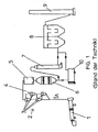
- Fig. 1 shows a schematic view of a device for cement clinker production according to the prior art.
- the device for producing cement clinker consists of a furnace system, in particular a rotary kiln 1, in which the raw materials for producing the cement clinker are burned.
- the raw materials are usually preheated in a preheating tower 2, which can consist of a plurality of cyclones 3 arranged one above the other.
- the raw materials are fed via a material feed 4 in the preheating tower 2.
- the raw material reaches the rotary kiln 1, whereas the flue gases A flow through the preheating tower 2 against the flow of the raw material.
- the raw gases A which contain both nitrogen oxides NO x and dust, enter a filter 5, where the dust content of the raw gases A is reduced accordingly.
- the raw gases A then pass into a catalytic converter 6, in which the nitrogen oxides NO x are partly converted into nitrogen N 2 and water H 2 O by a corresponding catalytic reaction.
- the denitrified raw gases A are passed through a possible cooling device 7, on the one hand to lower the flue gases A to a temperature which is suitable for a subsequent filter stage 8 for dedusting the flue gases A.
- the heat contained in the flue gases A can be recovered by such a cooling device 7 and used to heat the flue gases A upstream of the catalytic converter 6.
- the filter stage 8 which can be formed by bag filters or electrostatic precipitators, the denitrified and dedusted smoke gases A reach the atmosphere via a chimney 9.
- the fired raw material of the cement clinker conveyed with the flue gases A reaches a mill 10, where it is ground to a desired size before filling.
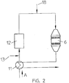
- Fig. 2 shows a denitrification device with regenerative afterburning of the carbon monoxide and the gaseous organic substances in the flue gases A.
- the flue gases A arrive after a conventional filtering (not shown) in a heat exchanger 11, where they are heated to the reaction temperature T R of the catalyst 6 from 160 ° C to 500 ° C.
- the heat exchanger 11 extracts the flue gases in the catalytic converter 6 and, if necessary, after a subsequent filter stage, so that the flue gases A are brought to the reaction temperature T R after entering the catalytic converter 6.
- heating the flue gases to the desired reaction temperature T R is not possible and external energy must be supplied.
- the losses of the heat displacement in the heat exchanger 11 are compensated for by the fact that the carbon monoxide CO and the gaseous organic substances in the flue gases A are burned.
- the carbon monoxide CO and the gaseous ones are also used in the post-combustion stage 12 organic substances in the flue gases are reduced.
- the nitrogen oxides generated in the afterburning in stage 12 or nitrogen oxides NO x contained in the flue gases are finally removed in the catalytic converter 6.
- a device 13 for supplying external thermal energy for example a natural gas line, can be arranged upstream of the afterburning stage 12.
- the device thus not only increases the efficiency by reducing the amount of external energy but also reduces both the nitrogen oxides NO x and the high content of carbon monoxide CO and gaseous organic substances. Due to the combustion of the carbon monoxide CO in the flue gases, the installation of an additional layer of a so-called oxidation catalyst is not necessary.
- An oxidation catalyst ensures the oxidation of the carbon monoxide CO to carbon dioxide CO 2 .
- Fig. 3 shows a used according to the invention Denoxing device with a combined heat accumulator and catalyst.
- the flue gases A are passed in an alternating direction through two channels 14 with a plurality of successive heat storage modules 15 and a space 16 arranged therebetween for regenerative afterburning of the carbon monoxide CO and the gaseous organic substances of the flue gases A.
- the direction of flow removes the thermal energy from the flue gases A in the heat storage modules 15, which is required to bring the flue gases A to the reaction temperature T R of the catalysts 6.
- Fuel such as natural gas can be supplied via a line 17.
- the substances required for the catalytic reduction in the catalysts 6, preferably ammonia, are added via corresponding lines 18 and 18a after the flow has been reversed.
- the alternating flow direction is controlled by appropriate control devices (not shown).
- the heat storage modules 15 can be formed by ceramic honeycomb bodies.
- the variant according to Fig. 3 requires catalysts 6 with a larger range of the reaction temperature T R , since the temperature cannot be kept constant due to the alternating direction of the flue gases A. You do not need your own heat exchanger 11, but this is integrated into the channels 14 by the heat storage modules 15. Due to the elimination of a separate heat exchanger 11, the expenditure on equipment is also lower.
Landscapes
- Engineering & Computer Science (AREA)
- Chemical & Material Sciences (AREA)
- Environmental & Geological Engineering (AREA)
- Oil, Petroleum & Natural Gas (AREA)
- Chemical Kinetics & Catalysis (AREA)
- Analytical Chemistry (AREA)
- General Chemical & Material Sciences (AREA)
- Biomedical Technology (AREA)
- Health & Medical Sciences (AREA)
- Exhaust Gas Treatment By Means Of Catalyst (AREA)
- Treating Waste Gases (AREA)
- Chimneys And Flues (AREA)
- Carbon And Carbon Compounds (AREA)
- Catalysts (AREA)
Description
Die Erfindung betrifft ein Verfahren gemäß dem Oberbegriff von Anspruch 1.The invention relates to a method according to the preamble of
Die vorliegende Erfindung bezieht sich auf die Entstickung von Rauchgasen, welche Kohlenstoffmonoxid und gasförmige organische Stoffe enthalten, nämlich Rauchgase, die bei der Zementklinkerherstellung anfallen, wo in Drehrohröfen die Rohstoffe, welche für die Zementklinkerbildung erforderlich sind, auf Temperaturen von 1350°C bis 1700°C aufgeheizt werden. Die Rohstoffe werden üblicherweise in einem Vorwärmturm bestehend aus mehreren hintereinander angeordneten Zyklonen vorgewärmt, bevor sie in den Drehrohrofen gelangen. Die Abgase durchströmen den Produktionsprozess im Gegenstrom zum Materialfluss und werden nach dem Verlassen der letzten Zyklonwärmstufe einer Abgasreinigung zugeführt. Bei der Entstickung, die einen Teil der Abluftreinigung darstellt, wird mit sogenannten SCR (selective catalytic reduction)-Katalysatoren durch Zugabe von Ammoniak bzw. Ammoniak abgebenden Verbindungen, wie z.B. Ammoniak-Wasser oder Harnstoff, bei optimaler Betriebstemperatur eine Spaltung der Stickoxide NOx in den Abgasen in umweltneutralen Luftstickstoff N2 und Wasser H2O erreicht. Die Abgase gelangen nach einer allfälligen Abkühlung bzw. Wärmerückgewinnung schlussendlich in eine Filterstufe, wo sie entstaubt werden, bevor sie in die Atmosphäre austreten. Die Filterstufe vor dem Austritt der Abgase in die Atmosphäre kann beispielsweise durch Elektro- oder Schlauchfilter gebildet werden.The present invention relates to the denitrification of flue gases which contain carbon monoxide and gaseous organic substances, namely flue gases which are produced in the production of cement clinker, where in rotary kilns the raw materials which are required for the formation of cement clinker are heated to temperatures of 1350 ° C. to 1700 ° C be heated. The raw materials are usually preheated in a preheating tower consisting of several cyclones arranged one behind the other before they reach the rotary kiln. The exhaust gases flow through the production process in counterflow to the material flow and are fed to an exhaust gas cleaning system after leaving the last cyclone heating stage. In the case of denitrification, which is part of the exhaust air purification, so-called SCR (selective catalytic reduction) catalysts are used to split the nitrogen oxides NO x in by adding ammonia or ammonia-releasing compounds, such as ammonia water or urea, at the optimum operating temperature the exhaust gases in environmentally neutral air nitrogen N 2 and water H 2 O are reached. After any cooling or heat recovery, the exhaust gases finally reach a filter stage, where they are dedusted before they escape into the atmosphere. The filter stage before the exhaust gases exit into the atmosphere can be formed, for example, by electrical or bag filters.
Der relativ hohe Staubanteil der Rohgase bei der Zementklinkerherstellung, führt zu einer raschen Verstopfung der Katalysatoren. Um die Standzeiten des Katalysators zu erhöhen, werden die Katalysatoren häufig reingasseitig, d.h. nach der Entstaubung der Rohgase, angeordnet. Nachteilig dabei ist, dass die Rauchgase vor der katalytischen Reduktion auf die notwendige Reaktionstemperatur von üblicherweise 160°C bis 500°C erwärmt werden müssen. Diese Erwärmung der Rauchgase erfolgt häufig durch einen Rekuperator bzw. Wärmetauscher, welcher den entstickten Rauchgasen die Wärme entzieht und den Rauchgasen vor der katalytischen Reduktion zuführt. Die Verluste der Wärmeverschiebung des Wärmeaustauschs machen eine zusätzliche Erwärmung der Rauchgase mittels externer Energie unbedingt erforderlich.The relatively high dust content of the raw gases in the production of cement clinker leads to a rapid blockage of the catalysts. In order to increase the service life of the catalyst, the catalysts are often arranged on the clean gas side, ie after the dedusting of the raw gases. The disadvantage here is that the flue gases have to be heated to the necessary reaction temperature of usually 160 ° C to 500 ° C before the catalytic reduction. This heating of the flue gases is often carried out by a recuperator or heat exchanger, which extracts the heat from the denitrified flue gases and from the flue gases leads to the catalytic reduction. The losses due to the heat displacement of the heat exchange make additional heating of the flue gases by means of external energy absolutely necessary.
Die
Die
Die
Die
Schließlich zeigt die
Die Aufgabe der vorliegenden Erfindung besteht darin, ein Verfahren der oben genannten Art zu schaffen durch welche der Einsatz externer Energie minimiert oder vermieden werden kann und dennoch ein hoher Entstickungsgrad erreicht werden kann. Nachteile bekannter Verfahren bzw. Vorrichtungen sollen reduziert bzw. vermieden werden.The object of the present invention is to provide a method of the type mentioned above by which the use of external energy can be minimized or avoided and a high degree of denitrification can be achieved. Disadvantages of known methods and devices should be reduced or avoided.
Gelöst wird die erfindungsgemäße Aufgabe durch ein Verfahren mit den Merkmalen von Anspruch 1. Die Nachverbrennung ist zur Reinigung von Rauchgasen bekannt. Darunter wird die Verbrennung von Rauchgasen zur Reduktion der organischen Substanzen verstanden. Bei der thermischen Nachverbrennung sind Verbrennungstemperaturen im Bereich von ca. 750 bis 900 °C üblich. Allenfalls werden zusätzliche Brennstoffe und Verbrennungsluft zugesetzt. Die katalytische Nachverbrennung ist durch einen in der Brennkammer enthaltenen Katalysator, welcher die Oxidationsprozesse beschleunigt, charakterisiert. Dadurch sind niedrigere Verbrennungstemperaturen von ca. 300 bis 500 °C notwendig. Bei der regenerativen Nachverbrennung kann die Zugabe von Brennstoff dadurch stark reduziert werden, dass die Rauchgastemperatur durch Wärmetausch bis fast auf die Verbrennungstemperatur erhöht wird. Erfindungsgemäß ist also vorgesehen, dass das Kohlenstoffmonoxid und die gasförmigen organischen Stoffe in den Rauchgasen nachverbrannt werden. Die bei der Nachverbrennung entstehende Energie wird erfindungsgemäß zur Erhöhung der Temperatur der Rauchgase auf die katalytische Reaktionstemperatur verwendet. Neben der energiesparenden Form der Erwärmung der Rauchgase für die katalytische Reduktion werden auch die in den Rauchgasen enthaltenen Kohlenmonoxide und/oder gasförmigen organischen Stoffe gesenkt. Die notwendige Energiemenge, beispielsweise in Form von Erdgas, kann durch das erfindungsgemäße Verfahren erheblich gesenkt werden, wobei die Zufuhr von externer Energie nur beim Anfahren notwendig ist. Der Aufwand für die Umsetzung des erfindungsgemäßen Verfahrens ist relativ gering und das Verfahren kostengünstig durchführbar. Durch die regenerative Nachverbrennung werden somit die Rauchgase nicht nur entstickt sondern auch deren Kohlenmonoxidgehalt und deren Gehalt an gasförmigen organischen Stoffen reduziert. Durch die Reduktion der gasförmigen organischen Stoffe, insbesondere organischer Verbindungen sogenannter "Volatile Organic Compounds" (VOCs), kann die Geruchsbelastung durch die Rauchgase reduziert werden.The object of the invention is achieved by a method having the features of
Die Rauchgase werden in alternierender Richtung durch mindestens zwei Kanäle mit mehreren aufeinanderfolgenden Wärmespeichermodulen und einem dazwischen angeordneten Raum zur regenerativen Nachverbrennung geleitet und die katalytische Reduktion der Stickoxide in zwischen den Wärmespeichermodulen angeordneten Katalysatoren durchgeführt. Dabei werden Wärmespeichermodule und Katalysatoren in Kanälen kombiniert und durch die alternierende Richtung der Rauchgase den Rauchgasen die für die katalytische Reduktion erforderliche Wärme entzogen. Durch die regenerative Nachverbrennung des Kohlenstoffmonoxids und der gasförmigen organischen Stoffe in den Rauchgasen kann das Verfahren autotherm, d.h. ohne externe Energiezuführung, ablaufen und somit ein hoher Wirkungsgrad erzielt werden.The flue gases are passed in an alternating direction through at least two channels with several successive heat storage modules and a space arranged therebetween for regenerative post-combustion, and the catalytic reduction of the nitrogen oxides is carried out in catalysts arranged between the heat storage modules. Heat storage modules and catalytic converters are combined in ducts and the flue gases are extracted from the flue gases by the alternating direction of the heat required for catalytic reduction. Due to the regenerative afterburning of the carbon monoxide and the gaseous organic substances in the flue gases, the process can be run without external energy supply, and thus a high degree of efficiency can be achieved.
Zum Starten der Entstickung der Rauchgase wird externe Wärmeenergie zugeführt. Diese externe Wärmeenergie kann beispielsweise durch Verbrennung von externen Energieträgern wie z.B. Erdgas oder Erdöl erzeugt werden.External thermal energy is supplied to start the denitrification of the flue gases. This external thermal energy can, for example, by burning external energy sources such as Natural gas or oil are generated.
Vorteilhafterweise werden die Rauchgase zu mindestens 60% entstickt.At least 60% of the flue gases are advantageously removed.
Die vorliegende Erfindung wird anhand der beigefügten Zeichnungen näher erläutert. Darin zeigen:
-
Fig. 1 eine schematische Darstellung der Anlage zur Zementklinkerherstellung nach dem Stand der Technik; -
Fig. 2 eine schematische Ansicht einer Entstickungsvorrichtung; und -
Fig. 3 eine Ausführungsform einer erfindungsgemäss verwendeten Entstickungsvorrichtung.
-
Fig. 1 a schematic representation of the plant for cement clinker production according to the prior art; -
Fig. 2 a schematic view of a denitrification device; and -
Fig. 3 an embodiment of a denitrification device used according to the invention.
Wie bereits erwähnt, ist es durch die Wärmerückgewinnung üblicherweise nicht möglich die Rauchgase A auf die erforderliche Reaktionstemperatur von vorzugsweise 160°C bis 500°C für die katalytische Reduktion im Katalysator 6 aufzuwärmen. Daher ist es nach dem Stand der Technik erforderlich, durch externe Energiezufuhr den Wärmeverlust auszugleichen. Die externe Energiezufuhr ist aufgrund der damit verbundenen Kosten jedoch zu vermeiden.As already mentioned, it is usually not possible to heat the flue gases A to the required reaction temperature of preferably 160 ° C. to 500 ° C. for the catalytic reduction in the
Claims (2)
- A process for denoxing carbon monoxide (CO) and flue gases (A) containing gaseous organic substances which develops during the production of cement clinker, by selective catalytic reduction of the nitrogen oxides (NO), wherein the flue gases (A) are directed in alternating direction through at least two channels (14) with several sequentially arranged heat storage modules (15), and catalytic reduction of the nitrogen oxides (NO) is performed in catalysers (6) arranged between the heat storage modules (15), and wherein the flue gases (A), prior to the catalytic reduction, are heated by heat exchange of the recovered residual heat of the denoxed flue gases (A) to a reaction temperature (T) of 160 °C to 500 °C, characterised in that the heat displacement losses from the heat exchange are compensated for by regenerative postcombustion of the carbon monoxide (CO) and the gaseous organic substances in the flue gases (A) in a space (16) arranged between the at least two channels (14), wherein external heat energy is supplied for start-up denoxing of the flue gases (A), so that the supply of external energy is only necessary during start-up.
- The process according to claim 1, characterised in that the flue gases (A) are denoxed to at least 60 %.
Priority Applications (4)
| Application Number | Priority Date | Filing Date | Title |
|---|---|---|---|
| PL13167684T PL2628528T3 (en) | 2009-07-15 | 2010-06-14 | Method and apparatus for denitrifying waste gases |
| SI201030281T SI2454008T2 (en) | 2009-07-15 | 2010-06-14 | Process for denoxing of flue gases |
| PL10727333T PL2454008T5 (en) | 2009-07-15 | 2010-06-14 | Process and apparatus for denoxing of flue gases |
| EP13167684.3A EP2628528B1 (en) | 2009-07-15 | 2010-06-14 | Method and apparatus for denitrifying waste gases |
Applications Claiming Priority (2)
| Application Number | Priority Date | Filing Date | Title |
|---|---|---|---|
| AT0110909A AT507773B1 (en) | 2009-07-15 | 2009-07-15 | METHOD AND APPARATUS FOR RELIEVING SMOKE GASES |
| PCT/AT2010/000212 WO2011006175A1 (en) | 2009-07-15 | 2010-06-14 | Process and apparatus for denoxing of flue gases |
Related Child Applications (2)
| Application Number | Title | Priority Date | Filing Date |
|---|---|---|---|
| EP13167684.3A Division EP2628528B1 (en) | 2009-07-15 | 2010-06-14 | Method and apparatus for denitrifying waste gases |
| EP13167684.3A Division-Into EP2628528B1 (en) | 2009-07-15 | 2010-06-14 | Method and apparatus for denitrifying waste gases |
Publications (3)
| Publication Number | Publication Date |
|---|---|
| EP2454008A1 EP2454008A1 (en) | 2012-05-23 |
| EP2454008B1 EP2454008B1 (en) | 2013-05-15 |
| EP2454008B2 true EP2454008B2 (en) | 2020-02-19 |
Family
ID=42537232
Family Applications (2)
| Application Number | Title | Priority Date | Filing Date |
|---|---|---|---|
| EP13167684.3A Active EP2628528B1 (en) | 2009-07-15 | 2010-06-14 | Method and apparatus for denitrifying waste gases |
| EP10727333.6A Active EP2454008B2 (en) | 2009-07-15 | 2010-06-14 | Process for denoxing of flue gases |
Family Applications Before (1)
| Application Number | Title | Priority Date | Filing Date |
|---|---|---|---|
| EP13167684.3A Active EP2628528B1 (en) | 2009-07-15 | 2010-06-14 | Method and apparatus for denitrifying waste gases |
Country Status (27)
| Country | Link |
|---|---|
| US (1) | US9314739B2 (en) |
| EP (2) | EP2628528B1 (en) |
| JP (1) | JP5695042B2 (en) |
| KR (1) | KR20120049263A (en) |
| CN (1) | CN102470320B (en) |
| AT (1) | AT507773B1 (en) |
| AU (1) | AU2010273179B2 (en) |
| BR (1) | BR112012001060A2 (en) |
| CA (1) | CA2767341C (en) |
| CL (1) | CL2012000106A1 (en) |
| CO (1) | CO6491036A2 (en) |
| DE (1) | DE202010018000U1 (en) |
| DK (1) | DK2454008T3 (en) |
| EG (1) | EG26752A (en) |
| ES (2) | ES2409706T5 (en) |
| HR (1) | HRP20130736T1 (en) |
| IN (1) | IN2012DN00364A (en) |
| MA (1) | MA33524B1 (en) |
| MX (1) | MX2012000325A (en) |
| PL (2) | PL2628528T3 (en) |
| PT (2) | PT2628528T (en) |
| RS (1) | RS52803B (en) |
| SI (2) | SI2628528T1 (en) |
| TN (1) | TN2011000650A1 (en) |
| UA (1) | UA103403C2 (en) |
| WO (1) | WO2011006175A1 (en) |
| ZA (1) | ZA201109520B (en) |
Families Citing this family (15)
| Publication number | Priority date | Publication date | Assignee | Title |
|---|---|---|---|---|
| EP2561920A1 (en) * | 2011-08-24 | 2013-02-27 | Alstom Technology Ltd | Method and system for NOx reduction in flue gas |
| DE102011111529B4 (en) * | 2011-08-31 | 2016-03-17 | Siegfried Woitkowitz | Process and apparatus for the catalytic, regenerative and thermal oxidation of combustible constituents in exhaust gases resulting from sorptive treatment of biogas |
| US8591844B1 (en) * | 2012-05-17 | 2013-11-26 | Fluor Technologies Corporation | Start up catalyst heating |
| AT513851B1 (en) * | 2013-05-27 | 2014-08-15 | Scheuch Gmbh | Device for catalytic denitrification and regenerative thermal afterburning |
| AT513597B1 (en) | 2013-05-27 | 2014-06-15 | Scheuch Gmbh | Process for catalytic denitrification and regenerative thermal afterburning |
| DE102013112210A1 (en) * | 2013-11-06 | 2015-05-07 | Thyssenkrupp Ag | Process for the purification of bypass gases of the cement or mineral industry as well as the cement or mineral industry |
| DE102015208029A1 (en) * | 2015-04-30 | 2016-11-03 | Dürr Systems GmbH | Cleaning device, calciner and method for purifying a raw gas stream |
| WO2016030207A1 (en) * | 2014-08-29 | 2016-03-03 | Dürr Systems GmbH | Purification device, use of a purification device and method for purifying a waste-gas flow |
| DE102014112425A1 (en) * | 2014-08-29 | 2016-03-03 | Dürr Systems GmbH | Treatment apparatus and method for treating an exhaust stream |
| DE102016119695A1 (en) | 2016-10-17 | 2018-04-19 | Thyssenkrupp Ag | Process and plant for the purification of preheater exhaust gases from a plant of the cement and / or mineral industry |
| DE102016121301A1 (en) | 2016-11-08 | 2018-05-09 | Thyssenkrupp Ag | Plant and method for cleaning an exhaust gas of a processing apparatus of the cement, lime or mineral industry |
| DE102017101507B4 (en) * | 2017-01-26 | 2022-10-13 | Chemisch Thermische Prozesstechnik Gmbh | Process and device for cleaning exhaust gases |
| CN112403258B (en) * | 2019-11-06 | 2021-10-26 | 中冶长天国际工程有限责任公司 | System and method for removing carbon monoxide and denitration of flue gas |
| CN115155302B (en) * | 2022-06-20 | 2023-12-08 | 成都易态科技有限公司 | Treatment system and treatment method for fuming furnace gas |
| US20240093867A1 (en) | 2022-09-08 | 2024-03-21 | Lummus Technology Llc | Selective catalytic reduction catalyst module support system and installation method |
Citations (2)
| Publication number | Priority date | Publication date | Assignee | Title |
|---|---|---|---|---|
| DE4432316A1 (en) † | 1993-07-23 | 1996-03-14 | Kvt Verfahrenstech Gmbh | Waste gas denitrification and removal of halogenated dibenzodioxine |
| AT505542A4 (en) † | 2008-03-06 | 2009-02-15 | Kirchdorfer Zementwerk Hofmann | System i.e. selective catalytic reduction denitrification system, for purifying e.g. nitrogen oxide, from cement-rotary furnace, has chamber, whose flue gas outlet has flow connection to flue gas inlet of catalyst, or exhaust gas outlet |
Family Cites Families (20)
| Publication number | Priority date | Publication date | Assignee | Title |
|---|---|---|---|---|
| DE3515551A1 (en) | 1985-04-30 | 1986-10-30 | Linde Ag, 6200 Wiesbaden | Process for removing impurities from a hot gas stream |
| DE3637395A1 (en) | 1986-11-03 | 1988-05-05 | Thyssen Industrie | Apparatus for the dinitration of flue gases |
| US5260043A (en) * | 1991-08-01 | 1993-11-09 | Air Products And Chemicals, Inc. | Catalytic reduction of NOx and carbon monoxide using methane in the presence of oxygen |
| US5224334A (en) | 1992-03-09 | 1993-07-06 | Radian Corporation | Low NOx cogeneration process and system |
| US5366708A (en) * | 1992-12-28 | 1994-11-22 | Monsanto Eviro-Chem Systems, Inc. | Process for catalytic reaction of gases |
| CH692181A5 (en) | 1995-09-08 | 2002-03-15 | Elex Ag | Flue gas cleaning system. |
| DE19705663A1 (en) | 1997-02-14 | 1998-04-23 | Siemens Ag | Removal of nitrous oxides and dust from flue gas |
| DE19720205B4 (en) | 1997-05-14 | 2006-05-18 | Johannes Schedler | Plant for cleaning exhaust gases laden with nitrogen oxides |
| SE518812C2 (en) * | 1998-03-17 | 2002-11-26 | Bjoern Heed | Catalytic regenerative device for purification of gases |
| JP2000274643A (en) | 1999-03-25 | 2000-10-03 | Takuma Co Ltd | Exhaust gas treating system |
| JP3771758B2 (en) | 1999-10-18 | 2006-04-26 | 三菱重工業株式会社 | CO gas-containing hazardous gas treatment equipment for closed spaces |
| DE10030613A1 (en) * | 2000-06-21 | 2002-01-03 | Kloeckner Humboldt Wedag | Plant for the thermal treatment of flour-like raw materials |
| JP2002147735A (en) | 2000-11-14 | 2002-05-22 | Babcock Hitachi Kk | Heat storage combustion apparatus |
| JP2003161424A (en) | 2001-11-20 | 2003-06-06 | Sintokogio Ltd | Heat accumulating combustion equipment |
| US7597864B2 (en) * | 2004-07-16 | 2009-10-06 | Breen Energy Solutions | Control of mercury and other elemental metal emissions using reaction stabilization device |
| CN1263532C (en) * | 2004-08-20 | 2006-07-12 | 李少泉 | Device for once removing SO2, NO, CO from smoke of coal-fired boiler |
| US7758831B2 (en) | 2004-09-30 | 2010-07-20 | Babcock Power Environmental Inc. | Systems and methods for removing materials from flue gas via regenerative selective catalytic reduction |
| JP3109606U (en) | 2004-12-28 | 2005-05-19 | 正▲キン▼ 頼 | Thermal storage SCR denitration and dioxin removal equipment |
| US7393511B2 (en) * | 2005-02-16 | 2008-07-01 | Basf Catalysts Llc | Ammonia oxidation catalyst for the coal fired utilities |
| US7682586B2 (en) * | 2006-08-22 | 2010-03-23 | Babcock Power Environmental, Inc. | Thermal decomposition of urea in a side stream of combustion flue gas using a regenerative heat exchanger |
-
2009
- 2009-07-15 AT AT0110909A patent/AT507773B1/en not_active IP Right Cessation
-
2010
- 2010-06-14 JP JP2012519844A patent/JP5695042B2/en not_active Expired - Fee Related
- 2010-06-14 US US13/384,371 patent/US9314739B2/en active Active
- 2010-06-14 MX MX2012000325A patent/MX2012000325A/en active IP Right Grant
- 2010-06-14 ES ES10727333T patent/ES2409706T5/en active Active
- 2010-06-14 CN CN201080031829.8A patent/CN102470320B/en not_active Expired - Fee Related
- 2010-06-14 WO PCT/AT2010/000212 patent/WO2011006175A1/en active Application Filing
- 2010-06-14 KR KR1020127003912A patent/KR20120049263A/en not_active Application Discontinuation
- 2010-06-14 BR BR112012001060-3A patent/BR112012001060A2/en not_active Application Discontinuation
- 2010-06-14 SI SI201032017T patent/SI2628528T1/en unknown
- 2010-06-14 RS RS20130227A patent/RS52803B/en unknown
- 2010-06-14 CA CA2767341A patent/CA2767341C/en not_active Expired - Fee Related
- 2010-06-14 ES ES13167684T patent/ES2804529T3/en active Active
- 2010-06-14 AU AU2010273179A patent/AU2010273179B2/en not_active Ceased
- 2010-06-14 EP EP13167684.3A patent/EP2628528B1/en active Active
- 2010-06-14 UA UAA201201304A patent/UA103403C2/en unknown
- 2010-06-14 SI SI201030281T patent/SI2454008T2/en unknown
- 2010-06-14 EP EP10727333.6A patent/EP2454008B2/en active Active
- 2010-06-14 DK DK10727333.6T patent/DK2454008T3/en active
- 2010-06-14 PL PL13167684T patent/PL2628528T3/en unknown
- 2010-06-14 PT PT131676843T patent/PT2628528T/en unknown
- 2010-06-14 PT PT107273336T patent/PT2454008E/en unknown
- 2010-06-14 DE DE202010018000U patent/DE202010018000U1/en not_active Expired - Lifetime
- 2010-06-14 PL PL10727333T patent/PL2454008T5/en unknown
-
2011
- 2011-12-20 TN TNP2011000650A patent/TN2011000650A1/en unknown
- 2011-12-22 ZA ZA2011/09520A patent/ZA201109520B/en unknown
-
2012
- 2012-01-12 EG EG2012010067A patent/EG26752A/en active
- 2012-01-13 CL CL2012000106A patent/CL2012000106A1/en unknown
- 2012-01-13 IN IN364DEN2012 patent/IN2012DN00364A/en unknown
- 2012-01-13 CO CO12004616A patent/CO6491036A2/en active IP Right Grant
- 2012-02-14 MA MA34626A patent/MA33524B1/en unknown
-
2013
- 2013-08-06 HR HRP20130736AT patent/HRP20130736T1/en unknown
Patent Citations (2)
| Publication number | Priority date | Publication date | Assignee | Title |
|---|---|---|---|---|
| DE4432316A1 (en) † | 1993-07-23 | 1996-03-14 | Kvt Verfahrenstech Gmbh | Waste gas denitrification and removal of halogenated dibenzodioxine |
| AT505542A4 (en) † | 2008-03-06 | 2009-02-15 | Kirchdorfer Zementwerk Hofmann | System i.e. selective catalytic reduction denitrification system, for purifying e.g. nitrogen oxide, from cement-rotary furnace, has chamber, whose flue gas outlet has flow connection to flue gas inlet of catalyst, or exhaust gas outlet |
Also Published As
Similar Documents
| Publication | Publication Date | Title |
|---|---|---|
| EP2454008B2 (en) | Process for denoxing of flue gases | |
| EP2569076B1 (en) | Process for cleaning offgases by means of regenerative thermal postcombustion | |
| EP2545337B1 (en) | Method and device for producing cement clinker | |
| EP2408541B1 (en) | Combined waste gas treatment of waste gas streams containing ammonia and nitrogen oxides in industrial plants | |
| EP3155322B1 (en) | Arrangement and procedure for the treatment of flue gas | |
| DE102017101507B4 (en) | Process and device for cleaning exhaust gases | |
| AT505542B1 (en) | APPENDIX FOR CLEANING THE SMOKE GASES OF AN OVEN | |
| WO2015036073A1 (en) | Method and installation for the purification of exhaust gases, having a regenerative post-combustion installation | |
| DE102014106991A1 (en) | Device for catalytic denitrification and regenerative thermal afterburning | |
| WO2018073239A1 (en) | Method and installation for cleaning pre-heater exhaust gases of an installation for the cement and/or mineral industry | |
| WO2011120059A2 (en) | Method and device for the denitrification of flue gases | |
| WO2016173785A1 (en) | Cleaning device, calcining system, and method for cleaning a raw gas flow | |
| DE3712977A1 (en) | DEVICE FOR CATALYTICALLY NICKELING SMOKE GASES | |
| WO2018087024A1 (en) | Installation and method for cleaning an exhaust gas of a processing device in the cement, lime or mineral industry | |
| DE102022105954A1 (en) | Device and method for producing cement clinker | |
| EP1915326B1 (en) | Method and device for removing volatile organic components from waste gases of a clinker installation | |
| DE102008013065A1 (en) | Flue gases cleaning system for cylindrical cement rotary kiln, has feeding device arranged between mixing chamber, heat exchanger or combustion device with reduction catalyst | |
| DE10036496B4 (en) | Process for the catalytically assisted thermal disposal of weak methane-containing landfill gases | |
| AT523972A1 (en) | Process for cleaning flue gases from cement clinker production, and process and device for producing cement clinker | |
| DE102021107533A1 (en) | Plant and process for the regenerative thermal oxidation of raw gas | |
| WO2019137737A1 (en) | Pollutant reduction of exhaust gases in the thermal treatment of materials |
Legal Events
| Date | Code | Title | Description |
|---|---|---|---|
| PUAI | Public reference made under article 153(3) epc to a published international application that has entered the european phase |
Free format text: ORIGINAL CODE: 0009012 |
|
| 17P | Request for examination filed |
Effective date: 20111229 |
|
| AK | Designated contracting states |
Kind code of ref document: A1 Designated state(s): AL AT BE BG CH CY CZ DE DK EE ES FI FR GB GR HR HU IE IS IT LI LT LU LV MC MK MT NL NO PL PT RO SE SI SK SM TR |
|
| AX | Request for extension of the european patent |
Extension state: RS |
|
| RAX | Requested extension states of the european patent have changed |
Extension state: RS Payment date: 20111229 |
|
| GRAP | Despatch of communication of intention to grant a patent |
Free format text: ORIGINAL CODE: EPIDOSNIGR1 |
|
| GRAS | Grant fee paid |
Free format text: ORIGINAL CODE: EPIDOSNIGR3 |
|
| GRAA | (expected) grant |
Free format text: ORIGINAL CODE: 0009210 |
|
| AK | Designated contracting states |
Kind code of ref document: B1 Designated state(s): AL AT BE BG CH CY CZ DE DK EE ES FI FR GB GR HR HU IE IS IT LI LT LU LV MC MK MT NL NO PL PT RO SE SI SK SM TR |
|
| AX | Request for extension of the european patent |
Extension state: RS |
|
| REG | Reference to a national code |
Ref country code: CH Ref legal event code: NV Representative=s name: E. BLUM AND CO. AG PATENT- UND MARKENANWAELTE , CH Ref country code: GB Ref legal event code: FG4D Free format text: NOT ENGLISH Ref country code: CH Ref legal event code: EP |
|
| REG | Reference to a national code |
Ref country code: PT Ref legal event code: SC4A Free format text: AVAILABILITY OF NATIONAL TRANSLATION Effective date: 20130528 |
|
| REG | Reference to a national code |
Ref country code: AT Ref legal event code: REF Ref document number: 611840 Country of ref document: AT Kind code of ref document: T Effective date: 20130615 |
|
| REG | Reference to a national code |
Ref country code: IE Ref legal event code: FG4D Free format text: LANGUAGE OF EP DOCUMENT: GERMAN |
|
| REG | Reference to a national code |
Ref country code: ES Ref legal event code: FG2A Ref document number: 2409706 Country of ref document: ES Kind code of ref document: T3 Effective date: 20130627 |
|
| REG | Reference to a national code |
Ref country code: DE Ref legal event code: R096 Ref document number: 502010003375 Country of ref document: DE Effective date: 20130711 |
|
| REG | Reference to a national code |
Ref country code: RO Ref legal event code: EPE |
|
| REG | Reference to a national code |
Ref country code: SK Ref legal event code: T3 Ref document number: E 14068 Country of ref document: SK |
|
| REG | Reference to a national code |
Ref country code: HR Ref legal event code: TUEP Ref document number: P20130736 Country of ref document: HR |
|
| REG | Reference to a national code |
Ref country code: DK Ref legal event code: T3 |
|
| REG | Reference to a national code |
Ref country code: EE Ref legal event code: FG4A Ref document number: E007998 Country of ref document: EE Effective date: 20130603 |
|
| REG | Reference to a national code |
Ref country code: NO Ref legal event code: T2 Effective date: 20130515 |
|
| REG | Reference to a national code |
Ref country code: SE Ref legal event code: TRGR |
|
| REG | Reference to a national code |
Ref country code: NL Ref legal event code: T3 |
|
| REG | Reference to a national code |
Ref country code: PL Ref legal event code: T3 |
|
| REG | Reference to a national code |
Ref country code: GR Ref legal event code: EP Ref document number: 20130401462 Country of ref document: GR Effective date: 20130829 |
|
| REG | Reference to a national code |
Ref country code: HR Ref legal event code: T1PR Ref document number: P20130736 Country of ref document: HR |
|
| PG25 | Lapsed in a contracting state [announced via postgrant information from national office to epo] |
Ref country code: IS Free format text: LAPSE BECAUSE OF FAILURE TO SUBMIT A TRANSLATION OF THE DESCRIPTION OR TO PAY THE FEE WITHIN THE PRESCRIBED TIME-LIMIT Effective date: 20130915 |
|
| PLBI | Opposition filed |
Free format text: ORIGINAL CODE: 0009260 |
|
| PG25 | Lapsed in a contracting state [announced via postgrant information from national office to epo] |
Ref country code: MC Free format text: LAPSE BECAUSE OF FAILURE TO SUBMIT A TRANSLATION OF THE DESCRIPTION OR TO PAY THE FEE WITHIN THE PRESCRIBED TIME-LIMIT Effective date: 20130515 |
|
| 26 | Opposition filed |
Opponent name: ELEX AG Effective date: 20140217 |
|
| PLAX | Notice of opposition and request to file observation + time limit sent |
Free format text: ORIGINAL CODE: EPIDOSNOBS2 |
|
| REG | Reference to a national code |
Ref country code: HU Ref legal event code: AG4A Ref document number: E018850 Country of ref document: HU |
|
| REG | Reference to a national code |
Ref country code: DE Ref legal event code: R026 Ref document number: 502010003375 Country of ref document: DE Effective date: 20140217 |
|
| PLAF | Information modified related to communication of a notice of opposition and request to file observations + time limit |
Free format text: ORIGINAL CODE: EPIDOSCOBS2 |
|
| PLBB | Reply of patent proprietor to notice(s) of opposition received |
Free format text: ORIGINAL CODE: EPIDOSNOBS3 |
|
| PG25 | Lapsed in a contracting state [announced via postgrant information from national office to epo] |
Ref country code: MT Free format text: LAPSE BECAUSE OF FAILURE TO SUBMIT A TRANSLATION OF THE DESCRIPTION OR TO PAY THE FEE WITHIN THE PRESCRIBED TIME-LIMIT Effective date: 20130515 |
|
| REG | Reference to a national code |
Ref country code: HR Ref legal event code: ODRP Ref document number: P20130736 Country of ref document: HR Payment date: 20150519 Year of fee payment: 6 |
|
| REG | Reference to a national code |
Ref country code: FR Ref legal event code: PLFP Year of fee payment: 6 |
|
| PG25 | Lapsed in a contracting state [announced via postgrant information from national office to epo] |
Ref country code: SM Free format text: LAPSE BECAUSE OF FAILURE TO SUBMIT A TRANSLATION OF THE DESCRIPTION OR TO PAY THE FEE WITHIN THE PRESCRIBED TIME-LIMIT Effective date: 20130515 |
|
| PG25 | Lapsed in a contracting state [announced via postgrant information from national office to epo] |
Ref country code: CY Free format text: LAPSE BECAUSE OF FAILURE TO SUBMIT A TRANSLATION OF THE DESCRIPTION OR TO PAY THE FEE WITHIN THE PRESCRIBED TIME-LIMIT Effective date: 20130515 |
|
| PG25 | Lapsed in a contracting state [announced via postgrant information from national office to epo] |
Ref country code: MK Free format text: LAPSE BECAUSE OF FAILURE TO SUBMIT A TRANSLATION OF THE DESCRIPTION OR TO PAY THE FEE WITHIN THE PRESCRIBED TIME-LIMIT Effective date: 20130515 |
|
| PGFP | Annual fee paid to national office [announced via postgrant information from national office to epo] |
Ref country code: HR Payment date: 20150519 Year of fee payment: 6 Ref country code: LU Payment date: 20150604 Year of fee payment: 6 Ref country code: LT Payment date: 20150522 Year of fee payment: 6 Ref country code: EE Payment date: 20150518 Year of fee payment: 6 |
|
| PGFP | Annual fee paid to national office [announced via postgrant information from national office to epo] |
Ref country code: LV Payment date: 20150519 Year of fee payment: 6 Ref country code: HU Payment date: 20150518 Year of fee payment: 6 |
|
| APAH | Appeal reference modified |
Free format text: ORIGINAL CODE: EPIDOSCREFNO |
|
| APBM | Appeal reference recorded |
Free format text: ORIGINAL CODE: EPIDOSNREFNO |
|
| APBP | Date of receipt of notice of appeal recorded |
Free format text: ORIGINAL CODE: EPIDOSNNOA2O |
|
| PLAB | Opposition data, opponent's data or that of the opponent's representative modified |
Free format text: ORIGINAL CODE: 0009299OPPO |
|
| APBQ | Date of receipt of statement of grounds of appeal recorded |
Free format text: ORIGINAL CODE: EPIDOSNNOA3O |
|
| R26 | Opposition filed (corrected) |
Opponent name: ELEX CEMCAT AG Effective date: 20140217 |
|
| REG | Reference to a national code |
Ref country code: FR Ref legal event code: PLFP Year of fee payment: 7 |
|
| REG | Reference to a national code |
Ref country code: LT Ref legal event code: MM4D Effective date: 20160614 |
|
| REG | Reference to a national code |
Ref country code: EE Ref legal event code: MM4A Ref document number: E007998 Country of ref document: EE Effective date: 20160630 |
|
| REG | Reference to a national code |
Ref country code: HR Ref legal event code: PBON Ref document number: P20130736 Country of ref document: HR Effective date: 20160614 |
|
| PG25 | Lapsed in a contracting state [announced via postgrant information from national office to epo] |
Ref country code: LT Free format text: LAPSE BECAUSE OF NON-PAYMENT OF DUE FEES Effective date: 20160614 |
|
| PG25 | Lapsed in a contracting state [announced via postgrant information from national office to epo] |
Ref country code: LV Free format text: LAPSE BECAUSE OF NON-PAYMENT OF DUE FEES Effective date: 20160614 |
|
| PG25 | Lapsed in a contracting state [announced via postgrant information from national office to epo] |
Ref country code: EE Free format text: LAPSE BECAUSE OF NON-PAYMENT OF DUE FEES Effective date: 20160630 Ref country code: HU Free format text: LAPSE BECAUSE OF NON-PAYMENT OF DUE FEES Effective date: 20160615 |
|
| REG | Reference to a national code |
Ref country code: FR Ref legal event code: PLFP Year of fee payment: 8 |
|
| PG25 | Lapsed in a contracting state [announced via postgrant information from national office to epo] |
Ref country code: HR Free format text: LAPSE BECAUSE OF NON-PAYMENT OF DUE FEES Effective date: 20160614 |
|
| REG | Reference to a national code |
Ref country code: DE Ref legal event code: R082 Ref document number: 502010003375 Country of ref document: DE Representative=s name: WUNDERLICH & HEIM PATENTANWAELTE PARTNERSCHAFT, DE |
|
| REG | Reference to a national code |
Ref country code: FR Ref legal event code: PLFP Year of fee payment: 9 |
|
| PG25 | Lapsed in a contracting state [announced via postgrant information from national office to epo] |
Ref country code: LU Free format text: LAPSE BECAUSE OF NON-PAYMENT OF DUE FEES Effective date: 20160614 |
|
| APBU | Appeal procedure closed |
Free format text: ORIGINAL CODE: EPIDOSNNOA9O |
|
| PGFP | Annual fee paid to national office [announced via postgrant information from national office to epo] |
Ref country code: FI Payment date: 20180620 Year of fee payment: 9 |
|
| PGFP | Annual fee paid to national office [announced via postgrant information from national office to epo] |
Ref country code: RO Payment date: 20180608 Year of fee payment: 9 |
|
| PG25 | Lapsed in a contracting state [announced via postgrant information from national office to epo] |
Ref country code: AL Free format text: LAPSE BECAUSE OF FAILURE TO SUBMIT A TRANSLATION OF THE DESCRIPTION OR TO PAY THE FEE WITHIN THE PRESCRIBED TIME-LIMIT Effective date: 20130515 |
|
| PGFP | Annual fee paid to national office [announced via postgrant information from national office to epo] |
Ref country code: DK Payment date: 20180620 Year of fee payment: 9 |
|
| PLAY | Examination report in opposition despatched + time limit |
Free format text: ORIGINAL CODE: EPIDOSNORE2 |
|
| PLBC | Reply to examination report in opposition received |
Free format text: ORIGINAL CODE: EPIDOSNORE3 |
|
| PLAY | Examination report in opposition despatched + time limit |
Free format text: ORIGINAL CODE: EPIDOSNORE2 |
|
| PLBC | Reply to examination report in opposition received |
Free format text: ORIGINAL CODE: EPIDOSNORE3 |
|
| PLAY | Examination report in opposition despatched + time limit |
Free format text: ORIGINAL CODE: EPIDOSNORE2 |
|
| PLBC | Reply to examination report in opposition received |
Free format text: ORIGINAL CODE: EPIDOSNORE3 |
|
| REG | Reference to a national code |
Ref country code: CH Ref legal event code: PK Free format text: TITEL |
|
| REG | Reference to a national code |
Ref country code: FI Ref legal event code: MAE |
|
| PUAH | Patent maintained in amended form |
Free format text: ORIGINAL CODE: 0009272 |
|
| STAA | Information on the status of an ep patent application or granted ep patent |
Free format text: STATUS: PATENT MAINTAINED AS AMENDED |
|
| REG | Reference to a national code |
Ref country code: DK Ref legal event code: EBP Effective date: 20190630 |
|
| PG25 | Lapsed in a contracting state [announced via postgrant information from national office to epo] |
Ref country code: FI Free format text: LAPSE BECAUSE OF NON-PAYMENT OF DUE FEES Effective date: 20190614 Ref country code: RO Free format text: LAPSE BECAUSE OF NON-PAYMENT OF DUE FEES Effective date: 20190614 |
|
| REG | Reference to a national code |
Ref country code: CH Ref legal event code: AELC |
|
| 27A | Patent maintained in amended form |
Effective date: 20200219 |
|
| AK | Designated contracting states |
Kind code of ref document: B2 Designated state(s): AL AT BE BG CH CY CZ DE DK EE ES FI FR GB GR HR HU IE IS IT LI LT LU LV MC MK MT NL NO PL PT RO SE SI SK SM TR |
|
| AX | Request for extension of the european patent |
Extension state: RS |
|
| REG | Reference to a national code |
Ref country code: DE Ref legal event code: R102 Ref document number: 502010003375 Country of ref document: DE |
|
| REG | Reference to a national code |
Ref country code: NL Ref legal event code: FP |
|
| REG | Reference to a national code |
Ref country code: SE Ref legal event code: RPEO |
|
| REG | Reference to a national code |
Ref country code: NO Ref legal event code: TB2 |
|
| REG | Reference to a national code |
Ref country code: GR Ref legal event code: EP Ref document number: 20200401326 Country of ref document: GR Effective date: 20200716 |
|
| PG25 | Lapsed in a contracting state [announced via postgrant information from national office to epo] |
Ref country code: DK Free format text: LAPSE BECAUSE OF NON-PAYMENT OF DUE FEES Effective date: 20190630 |
|
| REG | Reference to a national code |
Ref country code: SK Ref legal event code: T5 Ref document number: E 14068 Country of ref document: SK |
|
| REG | Reference to a national code |
Ref country code: ES Ref legal event code: DC2A Ref document number: 2409706 Country of ref document: ES Kind code of ref document: T5 Effective date: 20201027 |
|
| PGFP | Annual fee paid to national office [announced via postgrant information from national office to epo] |
Ref country code: PT Payment date: 20230602 Year of fee payment: 14 Ref country code: NO Payment date: 20230620 Year of fee payment: 14 Ref country code: NL Payment date: 20230620 Year of fee payment: 14 Ref country code: IE Payment date: 20230620 Year of fee payment: 14 Ref country code: FR Payment date: 20230622 Year of fee payment: 14 Ref country code: DE Payment date: 20230620 Year of fee payment: 14 Ref country code: CZ Payment date: 20230602 Year of fee payment: 14 Ref country code: BG Payment date: 20230620 Year of fee payment: 14 |
|
| PGFP | Annual fee paid to national office [announced via postgrant information from national office to epo] |
Ref country code: TR Payment date: 20230608 Year of fee payment: 14 Ref country code: SK Payment date: 20230613 Year of fee payment: 14 Ref country code: SI Payment date: 20230602 Year of fee payment: 14 Ref country code: SE Payment date: 20230622 Year of fee payment: 14 Ref country code: PL Payment date: 20230607 Year of fee payment: 14 Ref country code: GR Payment date: 20230616 Year of fee payment: 14 Ref country code: AT Payment date: 20230609 Year of fee payment: 14 |
|
| PGFP | Annual fee paid to national office [announced via postgrant information from national office to epo] |
Ref country code: BE Payment date: 20230619 Year of fee payment: 14 |
|
| PGFP | Annual fee paid to national office [announced via postgrant information from national office to epo] |
Ref country code: IT Payment date: 20230630 Year of fee payment: 14 Ref country code: GB Payment date: 20230622 Year of fee payment: 14 Ref country code: ES Payment date: 20230719 Year of fee payment: 14 Ref country code: CH Payment date: 20230702 Year of fee payment: 14 |