EP2453582B1 - Detecting of jamming affecting a communication user equipment - Google Patents
Detecting of jamming affecting a communication user equipment Download PDFInfo
- Publication number
- EP2453582B1 EP2453582B1 EP10191430.7A EP10191430A EP2453582B1 EP 2453582 B1 EP2453582 B1 EP 2453582B1 EP 10191430 A EP10191430 A EP 10191430A EP 2453582 B1 EP2453582 B1 EP 2453582B1
- Authority
- EP
- European Patent Office
- Prior art keywords
- user equipment
- communication
- cpich
- base node
- power
- Prior art date
- Legal status (The legal status is an assumption and is not a legal conclusion. Google has not performed a legal analysis and makes no representation as to the accuracy of the status listed.)
- Active
Links
Images


Classifications
-
- H—ELECTRICITY
- H04—ELECTRIC COMMUNICATION TECHNIQUE
- H04W—WIRELESS COMMUNICATION NETWORKS
- H04W24/00—Supervisory, monitoring or testing arrangements
- H04W24/04—Arrangements for maintaining operational condition
-
- H—ELECTRICITY
- H04—ELECTRIC COMMUNICATION TECHNIQUE
- H04B—TRANSMISSION
- H04B1/00—Details of transmission systems, not covered by a single one of groups H04B3/00 - H04B13/00; Details of transmission systems not characterised by the medium used for transmission
- H04B1/69—Spread spectrum techniques
- H04B1/707—Spread spectrum techniques using direct sequence modulation
- H04B1/7097—Interference-related aspects
-
- H—ELECTRICITY
- H04—ELECTRIC COMMUNICATION TECHNIQUE
- H04B—TRANSMISSION
- H04B1/00—Details of transmission systems, not covered by a single one of groups H04B3/00 - H04B13/00; Details of transmission systems not characterised by the medium used for transmission
- H04B1/69—Spread spectrum techniques
- H04B1/707—Spread spectrum techniques using direct sequence modulation
- H04B1/7097—Interference-related aspects
- H04B1/7103—Interference-related aspects the interference being multiple access interference
-
- H—ELECTRICITY
- H04—ELECTRIC COMMUNICATION TECHNIQUE
- H04K—SECRET COMMUNICATION; JAMMING OF COMMUNICATION
- H04K3/00—Jamming of communication; Counter-measures
- H04K3/20—Countermeasures against jamming
- H04K3/22—Countermeasures against jamming including jamming detection and monitoring
-
- H—ELECTRICITY
- H04—ELECTRIC COMMUNICATION TECHNIQUE
- H04K—SECRET COMMUNICATION; JAMMING OF COMMUNICATION
- H04K2203/00—Jamming of communication; Countermeasures
- H04K2203/10—Jamming or countermeasure used for a particular application
- H04K2203/16—Jamming or countermeasure used for a particular application for telephony
Definitions
- the present invention relates to a method of detecting a jamming transmitter effecting a communication user equipment according to the preamble part of claim 1.
- the present invention also relates to a user equipment configured to execute the said method and an evaluation unit with interfaces to the user equipment and with an application configured to execute said method.
- Contemporary cellular radio networks are known since many years now meanwhile based on different technologies. The broadest coverage still is held by the global system for mobile communications according to the so called GSM standard.
- a user equipment in such cellular network can move freely and may be handled over to various cells of the GSM networks as for instance described in GSM standard specification 3GPP ETSI TS 51.010 or the like.
- Contemporary radio networks are based on a cellular code division multiple access (CDMA) as for instance realized in the universal mobile telecommunication system (UMTS).
- CDMA code division multiple access
- UMTS universal mobile telecommunication system
- a user equipment in radio networks can be subject of being affected by a jamming transmitter - jamming in this context generally is performed by an instrument preventing a user equipment from receiving signals from its base station.
- the jammer effectively disables cellular phones mostly by broad frequency interference with communication frequencies of the user equipment at high power level.
- some jammer applications are meant to be legal for instances in places where phone call is to be suppressed due to silence conditions.
- Other jammers are applied during misuse for instances to interrupt security applications of user equipment or the like.
- Jammers are available for jamming GSM and also UMTS frequencies.
- jamming detecting and preventing solutions are known up to date basically only against GSM jammers. In this regard, it should be recognized that primary aim of an anti-jamming solution is to undoubtfully detect a jamming attack rather than preventing the same.
- An anti-jamming solution is known from WO 2007/019814 which however is restricted to the GSM standard.
- a method for detecting a jamming transmitter affecting a communication terminal is described wherein receipt radio channel signal levels are evaluated at periodic intervals on a signalling channel.
- the communication terminal detects a radio channel signal level that exceeds a predefined threshold value in the signalling channel but is nevertheless unable to decode a message content of a message, then this state is interpreted as an interference state and an alarm signal is emitted.
- the problem related with this GMS anti-jamming solution is its fundament on a predefined threshold value in the signalling channel and the receipt of a message content.
- a communication user equipment (UE) and a number of base node stations (BNS) are the basic components of a CDMA based radio network.
- the radio network (RN) may work in either a frequency division duplex (FDD) or also a time division duplex (TDD) mode.
- FDD frequency division duplex
- TDD time division duplex
- SC pseudonoise spread code
- CA serving cell coverage area
- CHI pseudonoise chip
- interferences of multiple base node stations and user equipments in the communication frequency channel are spectrally located between an upper frequency and a lower frequency of a communication frequency band. Consequently, a broad band "jamming like" interference in the multiple shared communication frequency channel cannot be considered as an extraordinary event but is on the contrary part of the usual state of operation. Such situation may also occur each time the number of users changes in said frequency band. The similar situation may also occur when a user equipment has a comparatively large or a comparatively small distance to a base node station. Also a similar situation may occur when a user equipment is in the reach of two base node stations in particular vice versa when two user equipments belong to the same or neighbouring cells of the CDMA based radio network. In conclusion, an anti-jamming solution to be successfully implemented in a CDMA based radio network technology is more sophisticating.
- WO 00/62437 discloses a method and apparatus for use in a wireless communication base station which provides real time continuous detection of inband jammers with negligible impact on base station cost.
- the jammer detection apparatus utilizes automatic gain control techniques, digital sampling and digital signal processing to identify anomalous frequency components in the receive power spectral density curve.
- a method of estimating the location of inband jammers is described using the computed received power spectral density curves of multiple base stations.
- a predefined threshold value for a signal level of a specific signalizing channel for a user equipment per se cannot be defined. Either the channel and/or the signal level is continuously changing depending on the surroundings of the network. Also, a message content as such can not be received unless a pseudonoise spread code is received by the communication user equipment. Consequently, without pseudonoise spread code neither transmission nor a content of a message is possible unless the pseudonoise spread code is known to the user equipment.
- the object of which is to provide an effective and reliable method and apparatus for detecting a jamming transmitter affecting a communication user equipment wherein the communication user equipment and a number of base node stations are components of a cellular code division multiple access based radio network like for instance frequency division duplex or time division duplex mode radio network. It is another object of the invention to provide such method and apparatus with a more elaborated anti-jamming concept allowing also detection of a jamming transmitter on a broad frequency range. In particular, it is a further object of the invention to provide a method and apparatus which allows for a warning against a jamming transmitter, i.e. not only detecting the instant situation of a jamming action but also foreseeing the approach of such situation.
- the solution to the latter object is of high interest as the solution would naturally allow the method and apparatus to react in due time for instance by sending an alarm before the jamming action interrupts any communication of the user equipment.
- the object is achieved by the method of the invention as claimed in claim 1.
- the object is also achieved by a developed configuration of the method as claimed in claim 4.
- the method and developed configuration thereof as outlined above may be implemented by digital circuits of any preferred kind, whereby the advantages associated with the digital circuits may be obtained.
- a single processor or other unit may fulfil the functions of several means recited in the claims - this in particular holds for a user equipment according to the concept of the invention.
- the object is achieved by particular preferred development of the user equipment as claimed in claim 16.
- the concept of the invention also leads to a evaluation unit with interfaces to the user equipment and with an application configured to execute the method of the invention as defined in claim 18.
- the instant invention starts from the consideration that the user equipment per se and without further measures cannot distinguish between a normal mode frequency disturbance and a jamming frequency disturbance - in the CDMA based radio network a user equipment is obliged to change a pseudonoise spread code, once a frequency disturbance becomes effective rather than sticking to one and the same pseudonoise spread code. This consideration leads the invention to the conclusion that once a jamming action becomes effective the user equipment will loose the pseudonoise spread code, which is essential for transmitting and transceiving messages.
- the pseudonoise spread code is received by the communication user equipment from a base node station in a downlink channel also denoted as common pilot channel (CPICH).
- CPICH common pilot channel
- the CPICH channel is a downlink channel broadcast by a node B with constant power and of a known bit sequence, here denoted as pseudonoise spread code. Its power is usually between 5 % and 15 % of the total node B transmit power.
- a common CPICH power is 10 % of the typical total transmit power of 43 dBm.
- the CPICH channel thus is used by the user equipment for a first complete identification of a primary scrambling code used for scrambling a signal unit to be transmitted or received from the node B.
- a contemporary CPICH is e.g.
- the CPICH contains 20 bits of data, which are either all zeros or can be employed as a pattern of alternating ones and zeros.
- the channel can be used for measurements of signal quality, usually comprising a set of cell selection criteria power parameters like RSCP and Ec/lo.
- cell selection criteria power parameters like RSCP and Ec/lo.
- the first selection criteria power parameter is a band and/or channel biased ratio parameter, namely the Ec/lo-ratio (CPICH_Ec/lo) formed by the received energy per pseudonoise chip (CHI) in the serving downlink channel (sCPICH) divided by the total received power spectral density at the communication user equipment antenna connector.
- CPICH_Ec/lo Ec/lo-ratio
- a further band and/or channel biased absolute parameter is specifically the received signal code power (CPICH RSCP) in the serving downlink channel for the pseudonoise spread code at the communication user equipment antenna connector.
- CPICH RSCP received signal code power
- the user equipment In the case if the user equipment has evaluated for a consecutive number of cycles, that the serving cell does not fulfil the cell selection criterion, e.g. in form of Ec/lo and RSCP conditions the user equipment shall initiate the measurements for all neighbouring cells. In the case such measurements also fail to fulfil the cell selection criterions finally after a certain period of time the user equipment is considered to be out of service area.
- the cell selection criterion e.g. in form of Ec/lo and RSCP
- the instant invention has realized that for an effective jamming detection it is further necessary to measure an unbiased received wide band power within the bandwidth of the communication user equipment receiver at the communication user equipment antenna connector.
- the concept of the invention proposes to verify three conditions which are sufficient to reliably detect a jamming transmitter action affecting the communication user equipment.
- the main concept proposed by the invention is to verify the conditions (a), (b), (c) as defined in claims 1 and in particular in claim 4. In particular, the basis is to verify that the biased parameters are not detectable, whereas the unbiased parameter has increased.
- the main concept proposed by the invention is to provide a concept of relative measurement, wherein the set of cell selection criteria power parameters in the communication link are measured at a first earlier time and at a second later time. This concept relies on the idea that an absolute measurement of power parameters or predefined threshold values are of negligible significance in a CDMA based radio network. Instead relative conditions like the comparison of a situation at a first earlier time and a second later time is important according to the invention.
- a further key concluding condition of the concept of the invention is given by verifying that the increased value of the unbiased parameter exceeds a basic noise floor by more than a threshold amount.
- the threshold amount is not fixed or predefined but of adjustable magnitude sufficient for affirmation of a receivable pseudonoise spread code.
- the invention has realized, that in the case an unbiased received wide band power exceeds a basic noise floor according to the standard a pseudonoise spread code should by receivable. Thus, e.g. the Ec/lo ratio or the received signal code power in the CPICH should be detectable. Therefore, once the conditions (a), (b) and (c) are all fulfilled, the only possibility remains that a jamming transmitter is affecting the communication user equipment.
- the concept of the invention relies on the relative situation between a first earlier and a second later time. The state of loss of the serving base node station at the second later time although the unbiased received wideband power has increased is a relative criterion comparing the situation to a first earlier time, thus adapted to the CDMA based technology.
- the concept of the invention thus directs away from absolute measures or predefined threshold values.
- a varieties of advantages are achieved by the concept proposed by the invention adapted to a CDMA based radio network.
- the concept also allows for further developments of the adjustable magnitude of the threshold amount for affirmation of a receivable pseudonoise spread code.
- the concept is adaptable to a variety of types of scramblers and scrambling codes.
- the type of scrambler and type of scrambling codes may vary depending on the specific type of cellular CDMA based radio network.
- the adjustable magnitude can be provided as for instance the threshold amount of a spread code gain value, which is based on a spreading factor of 256 and thus results in a spread code gain value of 24 dB.
- the concept of the invention has the advantage that it is extendable to a broad frequency range. Also the concept can be used for a warning concept, which indicates the approach of a jamming transmitter.
- the set of at least one base node stations is an active set of base node stations.
- the set of cells whose signals are used during a soft handoff in the standard is referred to as the active set. If a so called search finger finds a sufficiently strong signal in terms of high Ec/lo or RSCP from a new cell, this cell is added to the active set. Thus, the cells of the active set are checked more frequently than the rest. Thus, a handoff with a neighbouring cell within the active set is more likely.
- the active set comprises at least the serving base node station and/or a base node station with a strongest Ec/lo ratio and/or strongest RSCP.
- the further condition that the bias parameters are not detectable at the second later time - as referred to as (a), (aa), (aaa) or (aaaa) conditions in claims 1 and 7 to 9 can be extended for any of the at least one downlink channels in the communication frequency channel. i.e. the concept can be extended within the whole 5 MHz frequency channel and also to a frequency band or number of all frequencies bands. In particular, also all frequency bands of the UMTS communication frequency bands can be implemented. In particular, also the communication user equipment can be part of a cellular global system of mobile communication, thus may rely on a combination of UMTS and GMS anti-jamming measures.
- WO 2007/019814 incorporated by reference for GSM-anti-jamming measures in this application.
- the concept of the invention may also comprise verifying a further condition for warning a jamming transmitter affecting a communication user equipment.
- verifying a further condition for warning a jamming transmitter affecting a communication user equipment are outlined in the method claims 12 to 15. Basically, in the so called (d) condition in the claims the biased parameters are still detectable at the second later time, but each is significantly decreased. Thus, the so called (d)-condition is verified before verifying the so called (a)-condition of the concept of the invention. For instance, this applies to a case where the pseudonoise spread code is still detectable at the second later time but the Ec/lo ratio and the receipt signal code power RSCP are each decreased by more than 90 % compared to the first earlier time.
- a warning level can be made dependent on the amount of decrease of the bias ratio parameters.
- the warning level can be made dependent on the magnitude of a threshold amount.
- the warning level can be made dependent on the exceeding amount of wideband power over noise floor. For instance the larger the decrease of biased parameters and the larger the increase of unbiased parameters at the second later time is compared to the first earlier time, than the higher the warning level shall be. Also the warning level should increase with increasing threshold amount.
- a warning or alarm message can be present in the user equipment itself.
- the warning or alarm message can be also provided remotely from the user equipment; for instance by an evaluation unit which interfaces to the user equipment.
- evaluation unit can provide an application configured to execute the concept of the invention as described above.
- the evaluation unit can be an evaluation program starting in a memory.
- the evaluation unit is part of an application and alarm signal estimated by the application.
- the alarm signal can be transmitted via an antenna, which is spaced apart from the user equipment and has means of connection via the cellular radio network.
- a computer or the like can be connected to the cellular radio network and processes the transmission of alarm signals.
- Fig. 1 shows in principle a cellular code division multiple access (CDMA) based radio network RN.
- the radio network RN allows for several transmitters - here referred to as a user equipment UE - to send information simultaneously over a single communication channel. This allows several user equipments UE to share a bandwidth of different frequencies.
- the CDMA based network can employ a spread spectrum technology and a special coding scheme - for instance a frequency division duplex FDD or time division duplex TDD mode can allow multiple users to be multiplexed over the same physical channel.
- the spread spectrum signalling has a much higher data bandwidth than the data being communicated.
- the CDMA based radio network RN provides a set of at least one base node station - here for instance the serving base node station sBNS and the further base node station BNS, which are within reach of the user equipment UE.
- a communication link 1 in a serving cell #1 coverage area CA1 oft he sBNS#1 is provided between the communication user equipment #1 and the assigned serving base node station sBNS#1.
- the base node station BNS#2 and the serving base node station sBNS#1 form an active set of base node stations, which are both in reach of the user equipment UE#1.
- the sBNS#1 has the strongest communication link 1.
- the communication link 1 is adapted for transmitting a signal comprising multiple communication signal units SU between the communication user equipment UE#1 and the serving base node station sBNS#1.
- the communication signal unit SU forms the input of a scrambling code operation, wherein the signal unit SU is correlated with a pseudonoise spread code sSC in the serving cell coverage area CA1 of the serving base node station sBNS#1.
- the output signal of the scrambling code operation is a so called pseudonoise chip CHI formed by the scrambling encryption manipulating the original signal unit SU by means of the serving scrambling code sSC. This can be performed either by an additive or multiplicative scrambling operation as in principle known in the art.
- the pseudonoise chip CHI is transmitted in a multiple shared communication frequency channel as indicated in the communication link 1 of Fig. 1 and can be transmitted or received by the user equipment UE#1 only when the serving pseudonoise spread code sSC is known by the user equipment UE#1.
- the scrambling code SC i.e. the pseudonoise spread code is known, a signal unit can be received or transmitted by the user equipment UE#1.
- the pseudonoise spread code SC is received by the communication user equipment UE#1 as a serving pseudonoise spread code sSC as shown in Fig. 1 in a so called serving down link channel sCPICH.
- the CPICH contains 20 bits of data, which are either all zeros or in the case that space time transmit diversity is employed is a pattern of alternating ones and zeros for transmissions on the sBNS second antenna.
- the first antenna of a base node station always transmits all zeros for a CPICH.
- the CPICH downlink channel has a constant power and is of a known bit sequence. Its power is usually between 5 % and 15 % of the total BNS transmit power.
- a common CPICH power is of 10 % of the typical total transmit power of 43 dBm.
- the CPICH can be used for measurements of signal quality.
- a jammer affects the user equipment UE#1 by interfering with the multiple shared communication frequency channel as located in a communication frequency band.
- Frequency bands FBI to FBIXX are known, each having a bandwidth of approximately 60 MHz.
- Each frequency band comprises several communication frequency channels, each having a bandwidth of 5 MHz.
- the noise floor of 110 dBm can be defined based on a relative noise of 174 dBm/Hz.
- a staple power for an out of jamming region user equipment UE#10 is a piled up staple with a rather small amount of CPICH power, a larger amount of signal code power dedicated to the user equipment and a main portion of shared signal power.
- the latter is used by several user equipments in the same 5 MHz bandwidth of the communication frequency channel. Nevertheless, information can be retrieved for each user equipment according to the pseudonoise spread code provided by the serving base node station and also the further base node station to each of the user equipments.
- the shared signal power may vary rather often.
- user equipment UE#10 can uphold the communication link to the serving base node station sBNS#1.
- the reason for this is that even upon variation of the shared signal power nevertheless the CPICH power can be detected by the user equipment UE#10.
- the CPICH power normally is located not more than 24 dBm below the upper level of the staple power.
- due to the spread code gain value of instantly 24 dBm CPICH power and pseudonoise spread code SC can be detected by the user equipment UE#10 during normal operation.
- the cell selection criteria power parameters Ec/lo ratio - in the standard denoted as CPICH Ec/lo as well as the received signal code power CPICH RSCP will increase - thus overall the signal quality will increase.
- the distance between UE#10 and sBNS#1 is enlarged - for instance by moving to UE#20 ⁇ the biased parameter Ec/lo, i.e. ratio CPIHC Ec/lo and the received signal code power CPICH RSCP of the sBNS#1 will decrease but instead of those of the BNS#2 will increase.
- the soft-handover may occur between sBNS#1 and BNS#2 by moving UE#10 to UE#20. This situation is described for instance in 3GPP TS25.133.
- Fig. 1 Distinct from those normal operation interferences in the communication frequency channels is the situation shown in Fig. 1 due to the presence of a jammer J.
- the presence results in a user equipment UE#1 received staple power as shown in Fig. 2C .
- UE#1 received staple power as shown in Fig. 2C .
- the CPICH power therefore is not anymore in the spread code gain and consequently cannot be detected anymore.
- This situation is to be distinguished from the out of range situation as described in TS25.133 chapter 4.2.2.1. Namely, in the presently described situation of Fig. 1 and Fig. 2C the biased parameters are not detectable whereas the unbiased parameters have increased. The increase is due to the jamming power of jammer J. In the "out of service area" situation the unbiased parameters decrease as the biased parameters also decrease.
- this situation can be used to provide an effective concept of detecting a jamming transmitter affecting the user equipment UE#1 when also an unbiased received wideband power within the bandwidth of the communication user equipment receiver at the communication user equipment UE#1 antenna connector is measured.
- a third condition has to be met according to the concept of the invention.
- the increased value of the unbiased parameter exceeds a basic noise floor by more than a predefined threshold amount X wherein the threshold amount X is of adjustable magnitude sufficient for affirmation of receivable pseudonoise spread code.
- the pseudonoise spread code gain value has a magnitude of 24 dBm.
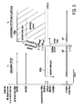
- Fig. 3 corresponds to an earlier time t 1 reflecting quantitatively the situation already shown in Fig. 2B .
- the right-hand side of Fig. 3 reflects a second later time corresponding quantitatively to the situation shown in Fig. 2C .
- Fig. 3 reflects e.g. moving from UE#10 to UE#1.
- the noise floor in Fig. 3 for both cases is located at - 110 dBm corresponding to 174 dBm/Hz and a 5 MHz frequency band FBI - presently, the frequency band FBI has an uplink frequency between 1920 - 1980 MHz and the downlink frequency between 2110 - 2170 MHz, the duplex distance is 190 MHz and a channel width is 5 MHz.
- the CPICH is still detectable and the CPICH power is located roughly at -90 dBm, thus 10dBm below the total wideband power WBp shown for the unjammed situation at -80 dBm.
- the CPICH channel power is within the spread code gain of -24 dBm.
- a CPICH power could be even detected down to -104 dBm.
- the increased value of the unbiased received wideband power WBp exceeds a basic noise floor NF by more than the threshold X, namely by more than the spread code gain value of 24 dBm.
- the condition (c) of the claims is met.
- neither an Ec/lo ratio nor a RSCP received signal code power can be detected as the CPICH power at -90 dBm is far below the wideband power minus the spread code gain - namely far below -64 dBm.
- the condition (a) listed in the claims is also positively verified.
- FIG. 3 right-hand side shows that the approved condition (c) as mentioned above indeed is necessary.
- the increased value of the unbiased received wideband power would be less than 24 dB over noise floor this could still result from an out of service area situation at time t 1 and time t 2 .
- a warning can be outputted by submitting an indicating jamming message from the user equipment UE#10 to an application and in particular still to any of the set of at least one base node station as long as the wideband power WBp is below the double slash on the dashed arrow in Fig. 3 .
- the biased parameters - namely Ec/lo and RSCP - in the serving downlink channel sCPICH for the pseudonoise spread code is still detectable at a later time t between t 1 and t 2 . But nevertheless each is significantly decreased, for instance decreased by more than 90 % compared to the first earlier time t 1 .
- a warning level can be given depending on the exceeding amount of the wideband power over noise floor NF. For instance a low warning level WL low can be given at time t' and a high warning level WL high can be given at time t".
- a low warning level WL low can be given at time t' and a high warning level WL high can be given at time t".
- the CPICH power is no more within the spread code gain and jamming is interrupting the communication link of UE#1 to sBNS#1.
- conditions (a), (b) and (c) are met and a jamming transmitter is affecting a communication user equipment UE#1.
- An indicating jamming message can be submitted from the user equipment UE#1 to an application and the application can further submit an alarm message. The alarm message can be conducted to other items of the network or controller stations.
- the warning level can also be increased with the magnitude of the threshold amount X.
- a warning level can be predominantly high the lower the threshold amount is - in this case the spread code gain is rather low and jamming can interrupt a communication link more effectively than in the case where the threshold amount is high.
- the invention relates to a method of detecting a jamming transmitter affecting a communication user equipment, wherein said communication user equipment (UE) and a number of base node stations (BNS) are components of a cellular code division multiple access (CDMA) based radio network (RN), wherein:
- UE communication user equipment
- BNS base node stations
- CDMA code division multiple access
Landscapes
- Engineering & Computer Science (AREA)
- Computer Networks & Wireless Communication (AREA)
- Signal Processing (AREA)
- Radar, Positioning & Navigation (AREA)
- Remote Sensing (AREA)
- Mobile Radio Communication Systems (AREA)
- Monitoring And Testing Of Transmission In General (AREA)
Description
- The present invention relates to a method of detecting a jamming transmitter effecting a communication user equipment according to the preamble part of
claim 1. The present invention also relates to a user equipment configured to execute the said method and an evaluation unit with interfaces to the user equipment and with an application configured to execute said method. - Contemporary cellular radio networks are known since many years now meanwhile based on different technologies. The broadest coverage still is held by the global system for mobile communications according to the so called GSM standard. A user equipment in such cellular network can move freely and may be handled over to various cells of the GSM networks as for instance described in GSM standard specification 3GPP ETSI TS 51.010 or the like.
- Contemporary radio networks are based on a cellular code division multiple access (CDMA) as for instance realized in the universal mobile telecommunication system (UMTS). The latter is increasingly important for security applications like camera systems or the like.
- Generally, a user equipment in radio networks can be subject of being affected by a jamming transmitter - jamming in this context generally is performed by an instrument preventing a user equipment from receiving signals from its base station. In use the jammer effectively disables cellular phones mostly by broad frequency interference with communication frequencies of the user equipment at high power level. Whereas some jammer applications are meant to be legal for instances in places where phone call is to be suppressed due to silence conditions. Other jammers are applied during misuse for instances to interrupt security applications of user equipment or the like. Jammers are available for jamming GSM and also UMTS frequencies. However, jamming detecting and preventing solutions are known up to date basically only against GSM jammers. In this regard, it should be recognized that primary aim of an anti-jamming solution is to undoubtfully detect a jamming attack rather than preventing the same.
- An anti-jamming solution is known from
WO 2007/019814 which however is restricted to the GSM standard. Therein a method for detecting a jamming transmitter affecting a communication terminal is described wherein receipt radio channel signal levels are evaluated at periodic intervals on a signalling channel. In the case that the communication terminal detects a radio channel signal level that exceeds a predefined threshold value in the signalling channel but is nevertheless unable to decode a message content of a message, then this state is interpreted as an interference state and an alarm signal is emitted. The problem related with this GMS anti-jamming solution is its fundament on a predefined threshold value in the signalling channel and the receipt of a message content. These features are somewhat specific for the GMS technology, however, less suited in the UMTS technology. More specifically it turns out that an anti jamming solution in the frame of a cellular code division multiple access based radio network is much more demanding. The state of dealing with disturbances in a communication frequency band of a user equipment is more or less a usual state of operation for a user equipment within a cellular code division multiple access based radio network. In particular, intracell and intercell interferences are generally accepted in a CDMA based radio network as long as a signal can be decoded. Thus, the state of operation naturally is permanently disturbed due to the CDMA based technology. A discrimination of a severe jamming action among these natural disturbances is still a problem to be solved. - The specific reason is as follows. A communication user equipment (UE) and a number of base node stations (BNS) are the basic components of a CDMA based radio network. The radio network (RN) may work in either a frequency division duplex (FDD) or also a time division duplex (TDD) mode. Once a communication link in a serving cell coverage area is provided between the communication user equipment and a serving base node station (sBNS) a communication signal unit (SU) is correlated with a pseudonoise spread code (SC) in a serving cell coverage area (CA) of a serving base node station and transmitted as a pseudonoise chip (CHI) in a multiple shared communication frequency channel. Thus, interferences of multiple base node stations and user equipments in the communication frequency channel are spectrally located between an upper frequency and a lower frequency of a communication frequency band. Consequently, a broad band "jamming like" interference in the multiple shared communication frequency channel cannot be considered as an extraordinary event but is on the contrary part of the usual state of operation. Such situation may also occur each time the number of users changes in said frequency band. The similar situation may also occur when a user equipment has a comparatively large or a comparatively small distance to a base node station. Also a similar situation may occur when a user equipment is in the reach of two base node stations in particular vice versa when two user equipments belong to the same or neighbouring cells of the CDMA based radio network. In conclusion, an anti-jamming solution to be successfully implemented in a CDMA based radio network technology is more sophisticating.
-
WO 00/62437 - In particular, as compared to the above mentioned GSM solution of
WO 2007/019814 a predefined threshold value for a signal level of a specific signalizing channel for a user equipment per se cannot be defined. Either the channel and/or the signal level is continuously changing depending on the surroundings of the network. Also, a message content as such can not be received unless a pseudonoise spread code is received by the communication user equipment. Consequently, without pseudonoise spread code neither transmission nor a content of a message is possible unless the pseudonoise spread code is known to the user equipment. - This is where the invention comes in. The object of which is to provide an effective and reliable method and apparatus for detecting a jamming transmitter affecting a communication user equipment wherein the communication user equipment and a number of base node stations are components of a cellular code division multiple access based radio network like for instance frequency division duplex or time division duplex mode radio network. It is another object of the invention to provide such method and apparatus with a more elaborated anti-jamming concept allowing also detection of a jamming transmitter on a broad frequency range. In particular, it is a further object of the invention to provide a method and apparatus which allows for a warning against a jamming transmitter, i.e. not only detecting the instant situation of a jamming action but also foreseeing the approach of such situation. The solution to the latter object is of high interest as the solution would naturally allow the method and apparatus to react in due time for instance by sending an alarm before the jamming action interrupts any communication of the user equipment.
- As regards the method, the object is achieved by the method of the invention as claimed in
claim 1. The object is also achieved by a developed configuration of the method as claimed in claim 4. - The method and developed configuration thereof as outlined above may be implemented by digital circuits of any preferred kind, whereby the advantages associated with the digital circuits may be obtained. A single processor or other unit may fulfil the functions of several means recited in the claims - this in particular holds for a user equipment according to the concept of the invention. As regards the apparatus, the object is achieved by particular preferred development of the user equipment as claimed in claim 16.
- In particular, the concept of the invention also leads to a evaluation unit with interfaces to the user equipment and with an application configured to execute the method of the invention as defined in claim 18.
- The instant invention starts from the consideration that the user equipment per se and without further measures cannot distinguish between a normal mode frequency disturbance and a jamming frequency disturbance - in the CDMA based radio network a user equipment is obliged to change a pseudonoise spread code, once a frequency disturbance becomes effective rather than sticking to one and the same pseudonoise spread code. This consideration leads the invention to the conclusion that once a jamming action becomes effective the user equipment will loose the pseudonoise spread code, which is essential for transmitting and transceiving messages.
- In cellular CDMA based radio networks the pseudonoise spread code is received by the communication user equipment from a base node station in a downlink channel also denoted as common pilot channel (CPICH). The CPICH channel is a downlink channel broadcast by a node B with constant power and of a known bit sequence, here denoted as pseudonoise spread code. Its power is usually between 5 % and 15 % of the total node B transmit power. A common CPICH power is 10 % of the typical total transmit power of 43 dBm. The CPICH channel thus is used by the user equipment for a first complete identification of a primary scrambling code used for scrambling a signal unit to be transmitted or received from the node B. A contemporary CPICH is e.g. transmitted using a spreading code 0 with the spreading factor of 256. The CPICH contains 20 bits of data, which are either all zeros or can be employed as a pattern of alternating ones and zeros. Once the scrambling code for a CPICH is known, the channel can be used for measurements of signal quality, usually comprising a set of cell selection criteria power parameters like RSCP and Ec/lo. There are most properly described in 3GPP TS25.133. Definitions and abbreviations or the like are known from 3GPP TS25.215. In particular, in chapter 4.2.2.1 of TS 25.133 an "out of coverage"-situation is defined using the cell criteria for power parameters as defined in the instant claims.
- The first selection criteria power parameter is a band and/or channel biased ratio parameter, namely the Ec/lo-ratio (CPICH_Ec/lo) formed by the received energy per pseudonoise chip (CHI) in the serving downlink channel (sCPICH) divided by the total received power spectral density at the communication user equipment antenna connector.
- A further band and/or channel biased absolute parameter is specifically the received signal code power (CPICH RSCP) in the serving downlink channel for the pseudonoise spread code at the communication user equipment antenna connector.
- In the case if the user equipment has evaluated for a consecutive number of cycles, that the serving cell does not fulfil the cell selection criterion, e.g. in form of Ec/lo and RSCP conditions the user equipment shall initiate the measurements for all neighbouring cells. In the case such measurements also fail to fulfil the cell selection criterions finally after a certain period of time the user equipment is considered to be out of service area.
- Based on these considerations, the instant invention has realized that for an effective jamming detection it is further necessary to measure an unbiased received wide band power within the bandwidth of the communication user equipment receiver at the communication user equipment antenna connector.
- Based on the above mentioned three power parameters, the concept of the invention proposes to verify three conditions which are sufficient to reliably detect a jamming transmitter action affecting the communication user equipment. The main concept proposed by the invention is to verify the conditions (a), (b), (c) as defined in
claims 1 and in particular in claim 4. In particular, the basis is to verify that the biased parameters are not detectable, whereas the unbiased parameter has increased. The main concept proposed by the invention is to provide a concept of relative measurement, wherein the set of cell selection criteria power parameters in the communication link are measured at a first earlier time and at a second later time. This concept relies on the idea that an absolute measurement of power parameters or predefined threshold values are of negligible significance in a CDMA based radio network. Instead relative conditions like the comparison of a situation at a first earlier time and a second later time is important according to the invention. - Additionally, a further key concluding condition of the concept of the invention is given by verifying that the increased value of the unbiased parameter exceeds a basic noise floor by more than a threshold amount. Essentially, the threshold amount is not fixed or predefined but of adjustable magnitude sufficient for affirmation of a receivable pseudonoise spread code.
- The invention has realized, that in the case an unbiased received wide band power exceeds a basic noise floor according to the standard a pseudonoise spread code should by receivable. Thus, e.g. the Ec/lo ratio or the received signal code power in the CPICH should be detectable. Therefore, once the conditions (a), (b) and (c) are all fulfilled, the only possibility remains that a jamming transmitter is affecting the communication user equipment. In particular, the concept of the invention relies on the relative situation between a first earlier and a second later time. The state of loss of the serving base node station at the second later time although the unbiased received wideband power has increased is a relative criterion comparing the situation to a first earlier time, thus adapted to the CDMA based technology.
- The concept of the invention thus directs away from absolute measures or predefined threshold values. As compared to common place measures, a varieties of advantages are achieved by the concept proposed by the invention adapted to a CDMA based radio network. In particular, the concept also allows for further developments of the adjustable magnitude of the threshold amount for affirmation of a receivable pseudonoise spread code. Thus, the concept is adaptable to a variety of types of scramblers and scrambling codes. The type of scrambler and type of scrambling codes may vary depending on the specific type of cellular CDMA based radio network. However, once the scrambling code for a CPICH is known, the adjustable magnitude can be provided as for instance the threshold amount of a spread code gain value, which is based on a spreading factor of 256 and thus results in a spread code gain value of 24 dB.
- Also the concept of the invention has the advantage that it is extendable to a broad frequency range. Also the concept can be used for a warning concept, which indicates the approach of a jamming transmitter.
- These and other developed configurations of the invention are further outlined in the dependent claims. Thereby, the mentioned advantages of the proposed concept are even more improved.
- In particular the set of at least one base node stations is an active set of base node stations. The set of cells whose signals are used during a soft handoff in the standard is referred to as the active set. If a so called search finger finds a sufficiently strong signal in terms of high Ec/lo or RSCP from a new cell, this cell is added to the active set. Thus, the cells of the active set are checked more frequently than the rest. Thus, a handoff with a neighbouring cell within the active set is more likely. In the preferred embodiment, the active set comprises at least the serving base node station and/or a base node station with a strongest Ec/lo ratio and/or strongest RSCP. Thus, advantageously in a further prepared development the method of detecting can be made even more reliable by further verifying the conditions of the concept with regard to the strongest cell.
- In a further preferred embodiment, the further condition that the bias parameters are not detectable at the second later time - as referred to as (a), (aa), (aaa) or (aaaa) conditions in
claims 1 and 7 to 9 can be extended for any of the at least one downlink channels in the communication frequency channel. i.e. the concept can be extended within the whole 5 MHz frequency channel and also to a frequency band or number of all frequencies bands. In particular, also all frequency bands of the UMTS communication frequency bands can be implemented. In particular, also the communication user equipment can be part of a cellular global system of mobile communication, thus may rely on a combination of UMTS and GMS anti-jamming measures. Here the embodiments ofWO 2007/019814 incorporated by reference for GSM-anti-jamming measures in this application. - In a particular preferred developed configuration, the concept of the invention may also comprise verifying a further condition for warning a jamming transmitter affecting a communication user equipment. These and further preferred developments are outlined in the method claims 12 to 15. Basically, in the so called (d) condition in the claims the biased parameters are still detectable at the second later time, but each is significantly decreased. Thus, the so called (d)-condition is verified before verifying the so called (a)-condition of the concept of the invention. For instance, this applies to a case where the pseudonoise spread code is still detectable at the second later time but the Ec/lo ratio and the receipt signal code power RSCP are each decreased by more than 90 % compared to the first earlier time. The development provides an effective concept for warning of a jamming transmitter once the conditions (d), (b) and (c) are fulfilled. As a result, the concept of the development allows to submit a message warning or indicating that a jamming transmitter is affecting the communication user equipment. In particular, a warning level can be made dependent on the amount of decrease of the bias ratio parameters. Also, the warning level can be made dependent on the magnitude of a threshold amount. Also the warning level can be made dependent on the exceeding amount of wideband power over noise floor. For instance the larger the decrease of biased parameters and the larger the increase of unbiased parameters at the second later time is compared to the first earlier time, than the higher the warning level shall be. Also the warning level should increase with increasing threshold amount.
- In a particular preferred embodiment in case of a jamming action a warning or alarm message can be present in the user equipment itself. Preferably, the warning or alarm message can be also provided remotely from the user equipment; for instance by an evaluation unit which interfaces to the user equipment. Such evaluation unit can provide an application configured to execute the concept of the invention as described above.
- For instance, the evaluation unit can be an evaluation program starting in a memory. In particular, the evaluation unit is part of an application and alarm signal estimated by the application. For instance, the alarm signal can be transmitted via an antenna, which is spaced apart from the user equipment and has means of connection via the cellular radio network. In particular, a computer or the like can be connected to the cellular radio network and processes the transmission of alarm signals.
- A particular preferred concept of such remote activation of an alarm message is best described in the embodiments of
WO 2007/019814 in principle which is incorporated by reference for this purpose in this application. - For a more complete understanding of the invention, the invention will now be described in detail with reference to the accompanying drawing. The detailed description will illustrate and describe what is considered as a preferred embodiment of the invention.
- In the drawing:
-
Fig. 1 shows a simplified symbolic graphic of a structure of a CDMA based radio network; -
Fig. 2A is a graphic illustrating the correlation of a pseudonoise spread code SC with a communication signal unit SU to provide a pseudonoise chip CHI in a multiple shared communication frequency channel; -
Fig. 2B illustratively symbolizes a base node station staple power for a user equipment in a 5 MHz frequency band, i.e. representing the CDMA code staple method of the radio network ofFig. 1 ; -
Fig. 2C illustrates the same situation as shown inFig. 2B , however, including also a jamming power on top of the base node station staple power ofFig. 2B measured by the user equipment in a 5 MHz frequency band; -
Fig. 3 illustrates more quantitatively an examplifying situation showing the user equipment staple power at a first earlier time and the second later time with a detectable CPICH as compared to an undetectable CPICH due to jamming. -
Fig. 1 shows in principle a cellular code division multiple access (CDMA) based radio network RN. The radio network RN allows for several transmitters - here referred to as a user equipment UE - to send information simultaneously over a single communication channel. This allows several user equipments UE to share a bandwidth of different frequencies. The CDMA based network can employ a spread spectrum technology and a special coding scheme - for instance a frequency division duplex FDD or time division duplex TDD mode can allow multiple users to be multiplexed over the same physical channel. The spread spectrum signalling has a much higher data bandwidth than the data being communicated. The CDMA based radio network RN provides a set of at least one base node station - here for instance the serving base node station sBNS and the further base node station BNS, which are within reach of the user equipment UE. For instance acommunication link 1 in a servingcell # 1 coverage area CA1 oft hesBNS# 1 is provided between the communicationuser equipment # 1 and the assigned serving base nodestation sBNS# 1. As the userequipment UE# 1 is also in the cell coverage area CA2 of the base nodestation BNS# 2, the base nodestation BNS# 2 and the serving base nodestation sBNS# 1 form an active set of base node stations, which are both in reach of the userequipment UE# 1. In the present embodiment thesBNS# 1 has thestrongest communication link 1. - The
communication link 1 is adapted for transmitting a signal comprising multiple communication signal units SU between the communication userequipment UE# 1 and the serving base nodestation sBNS# 1. As exemplified inFig. 2A the communication signal unit SU forms the input of a scrambling code operation, wherein the signal unit SU is correlated with a pseudonoise spread code sSC in the serving cell coverage area CA1 of the serving base nodestation sBNS# 1. The output signal of the scrambling code operation is a so called pseudonoise chip CHI formed by the scrambling encryption manipulating the original signal unit SU by means of the serving scrambling code sSC. This can be performed either by an additive or multiplicative scrambling operation as in principle known in the art. - As a result, the pseudonoise chip CHI is transmitted in a multiple shared communication frequency channel as indicated in the
communication link 1 ofFig. 1 and can be transmitted or received by the userequipment UE# 1 only when the serving pseudonoise spread code sSC is known by the userequipment UE# 1. Once, the scrambling code SC, i.e. the pseudonoise spread code is known, a signal unit can be received or transmitted by the userequipment UE# 1. - The pseudonoise spread code SC is received by the communication user
equipment UE# 1 as a serving pseudonoise spread code sSC as shown inFig. 1 in a so called serving down link channel sCPICH. The CPICH contains 20 bits of data, which are either all zeros or in the case that space time transmit diversity is employed is a pattern of alternating ones and zeros for transmissions on the sBNS second antenna. The first antenna of a base node station always transmits all zeros for a CPICH. The CPICH downlink channel has a constant power and is of a known bit sequence. Its power is usually between 5 % and 15 % of the total BNS transmit power. A common CPICH power is of 10 % of the typical total transmit power of 43 dBm. The CPICH can be used for measurements of signal quality. - In the instant embodiment, a jammer affects the user
equipment UE# 1 by interfering with the multiple shared communication frequency channel as located in a communication frequency band. Frequency bands FBI to FBIXX are known, each having a bandwidth of approximately 60 MHz. Each frequency band comprises several communication frequency channels, each having a bandwidth of 5 MHz. For each frequency channel, therefore the noise floor of 110 dBm can be defined based on a relative noise of 174 dBm/Hz. - As shown in
Fig. 2B , a staple power for an out of jamming region userequipment UE# 10 is a piled up staple with a rather small amount of CPICH power, a larger amount of signal code power dedicated to the user equipment and a main portion of shared signal power. The latter is used by several user equipments in the same 5 MHz bandwidth of the communication frequency channel. Nevertheless, information can be retrieved for each user equipment according to the pseudonoise spread code provided by the serving base node station and also the further base node station to each of the user equipments. - Once the number of user equipments changes in a coverage area CA1 of the service
base node station 1 the shared signal power may vary rather often. However, as the serving pseudonoise spread code SSC is available for the userequipment UE# 10 even upon variation of the shared signal power, userequipment UE# 10 can uphold the communication link to the serving base nodestation sBNS# 1. The reason for this is that even upon variation of the shared signal power nevertheless the CPICH power can be detected by the userequipment UE# 10. The CPICH power normally is located not more than 24 dBm below the upper level of the staple power. Thus, due to the spread code gain value of instantly 24 dBm CPICH power and pseudonoise spread code SC can be detected by the userequipment UE# 10 during normal operation. - In the case the distance between serving base node
station sBNS# 1 and userequipment UE# 10 is diminished like for instance the distance betweensBNS# 1 and UE10 the cell selection criteria power parameters Ec/lo ratio - in the standard denoted as CPICH Ec/lo as well as the received signal code power CPICH RSCP will increase - thus overall the signal quality will increase. However, in the case the distance betweenUE# 10 andsBNS# 1 is enlarged - for instance by moving to UE#20 ― the biased parameter Ec/lo, i.e. ratio CPIHC Ec/lo and the received signal code power CPICH RSCP of thesBNS# 1 will decrease but instead of those of theBNS# 2 will increase. Thus, upon a situation, the soft-handover may occur betweensBNS# 1 andBNS# 2 by movingUE# 10 to UE#20. This situation is described for instance in 3GPP TS25.133. - Distinct from those normal operation interferences in the communication frequency channels is the situation shown in
Fig. 1 due to the presence of a jammer J. The presence results in a userequipment UE# 1 received staple power as shown inFig. 2C . Additional to the CPICH power the dedicated signal code and the shared signal power a large pile of jamming power on top of the staple power ofFig. 2B is detected byUE# 1. As can be easily already seen fromFig. 2C , the CPICH power therefore is not anymore in the spread code gain and consequently cannot be detected anymore. This situation is to be distinguished from the out of range situation as described in TS25.133 chapter 4.2.2.1. Namely, in the presently described situation ofFig. 1 andFig. 2C the biased parameters are not detectable whereas the unbiased parameters have increased. The increase is due to the jamming power of jammer J. In the "out of service area" situation the unbiased parameters decrease as the biased parameters also decrease. - Consequently, according to the concept of the invention this situation can be used to provide an effective concept of detecting a jamming transmitter affecting the user
equipment UE# 1 when also an unbiased received wideband power within the bandwidth of the communication user equipment receiver at the communication userequipment UE# 1 antenna connector is measured. Upon verifying the condition that the biased parameters - namely the Ec/lo and RSCCI ― are not detectable and the unbiased parameter has increased a first indication of a jamming transmitter is given. However, to consolidate this finding a third condition has to be met according to the concept of the invention. - As best retrieved from
Fig. 3 , it is to be verified that the increased value of the unbiased parameter exceeds a basic noise floor by more than a predefined threshold amount X wherein the threshold amount X is of adjustable magnitude sufficient for affirmation of receivable pseudonoise spread code. In the present case, the pseudonoise spread code gain value has a magnitude of 24 dBm. - The left-hand side of
Fig. 3 corresponds to an earlier time t1 reflecting quantitatively the situation already shown inFig. 2B . The right-hand side ofFig. 3 reflects a second later time corresponding quantitatively to the situation shown inFig. 2C . Thus,Fig. 3 reflects e.g. moving fromUE# 10 toUE# 1. The noise floor inFig. 3 for both cases is located at - 110 dBm corresponding to 174 dBm/Hz and a 5 MHz frequency band FBI - presently, the frequency band FBI has an uplink frequency between 1920 - 1980 MHz and the downlink frequency between 2110 - 2170 MHz, the duplex distance is 190 MHz and a channel width is 5 MHz. - At an earlier point of time t1 the CPICH is still detectable and the CPICH power is located roughly at -90 dBm, thus 10dBm below the total wideband power WBp shown for the unjammed situation at -80 dBm. Thus the CPICH channel power is within the spread code gain of -24 dBm. A CPICH power could be even detected down to -104 dBm.
- The situation changes when the unbiased received wideband power WBp within the bandwidth of the communication user equipment receiver at the communication user
equipment UE# 1 antenna connector is increased due to the jamming power of the jammer J. This situation is shown at a later time t2, wherein the CPICH is no more detectable due to jamming. As outlined already, the biggest received wideband power WBp at the second later time t2 compared to the first earlier time t1 has increased as shown by the dashed arrow between the left-hand side and the right-hand side ofFig. 3 . Thus, the condition (b) of the claims and as shown above is positively verified. Furthermore, the increased value of the unbiased received wideband power WBp exceeds a basic noise floor NF by more than the threshold X, namely by more than the spread code gain value of 24 dBm. Thus the condition (c) of the claims is met. On the other hand, neither an Ec/lo ratio nor a RSCP received signal code power can be detected as the CPICH power at -90 dBm is far below the wideband power minus the spread code gain - namely far below -64 dBm. Thus the condition (a) listed in the claims is also positively verified. - Consequently, the situation at later time t2 is a jamming situation. Also
Fig. 3 right-hand side shows that the approved condition (c) as mentioned above indeed is necessary. In the case the increased value of the unbiased received wideband power would be less than 24 dB over noise floor this could still result from an out of service area situation at time t1 and time t2. - In a further embodiment not shown here, a warning can be outputted by submitting an indicating jamming message from the user
equipment UE# 10 to an application and in particular still to any of the set of at least one base node station as long as the wideband power WBp is below the double slash on the dashed arrow inFig. 3 . In this case, it is to be assumed that the biased parameters - namely Ec/lo and RSCP - in the serving downlink channel sCPICH for the pseudonoise spread code is still detectable at a later time t between t1 and t2. But nevertheless each is significantly decreased, for instance decreased by more than 90 % compared to the first earlier time t1. In this case a warning level can be given depending on the exceeding amount of the wideband power over noise floor NF. For instance a low warning level WLlow can be given at time t' and a high warning level WLhigh can be given at time t". At later time wherein the wideband power WBp is beyond the double flash the CPICH power is no more within the spread code gain and jamming is interrupting the communication link ofUE# 1 tosBNS# 1. In this case conditions (a), (b) and (c) are met and a jamming transmitter is affecting a communication userequipment UE# 1. An indicating jamming message can be submitted from the userequipment UE# 1 to an application and the application can further submit an alarm message. The alarm message can be conducted to other items of the network or controller stations. - The warning level can also be increased with the magnitude of the threshold amount X. For instance, a warning level can be predominantly high the lower the threshold amount is - in this case the spread code gain is rather low and jamming can interrupt a communication link more effectively than in the case where the threshold amount is high.
- The invention relates to a method of detecting a jamming transmitter affecting a communication user equipment, wherein said communication user equipment (UE) and a number of base node stations (BNS) are components of a cellular code division multiple access (CDMA) based radio network (RN), wherein:
- a communication signal unit (SU) is correlated with a pseudonoise spread code (SC) in a serving cell coverage area (CA) of a serving base node station (sBNS) and transmitted as a pseudonoise chip (CHI) in a multiple shared communication frequency channel spectrally located between an upper frequency and a lower frequency of a communication frequency band (FB I-XIX) and
- the pseudonoise spread code (SC) is received by the communication user equipment (UE) as a serving pseudonoise spread code (sSC) from said serving base node station (BNS) in a serving downlink channel (sCPICH).
Claims (18)
- Method of detecting a jamming transmitter affecting a communication user equipment, said communication user equipment (UE) and a number of base node stations (BNS) are components of a cellular code division multiple access based radio network (RN), wherein:a communication link in a serving cell coverage area (CA) is provided between the communication user equipment (UE) and at least an assigned serving base node station (sBNS) of said set of at least one base node stations (BNS), whereinsaid communication link being adapted for transmitting a signal comprising multiple communication signal units between the communication user equipment (UE) and at least the serving base node station (sBNS)
and the communication signal unit (SU) is correlated with a pseudonoise spread code (SC) in a serving cell coverage area (CA) of the serving base node station (sBNS), wherein a pseudonoise chip (CHI) is formed by manipulating the communication signal unit (SU) by means of the pseudonoise spread code (SC) in a scrambling encryption and the communication signal unit (SU) is transmitted as the pseudonoise chip (CHI) in a multiple shared communication frequency channel spectrally located between an upper frequency and a lower frequency of a communication frequency band andthe pseudonoise spread code (SC) is received by the communication user equipment (UE) as a serving pseudonoise spread code (sSC) from said serving base node station (BNS) in a serving downlink channel (sCPICH)
characterized by the steps of:- measuring a set of cell selection criteria power parameters (S) in the communication link at a first earlier time (t1) and at a second later time (t2), the power parameters (S) comprising- a band and/or channel biased ratio-parameter significant for the received power per chip (CHI) relative to a total received power at the communication user equipment (UE) antenna connector,- a band and/or channel biased absolute-parameter significant for the received signal power for the pseudonoise spread code (SC) at the communication user equipment (UE) antenna connector,- an unbiased received wide band power within the bandwidth of the communication user equipment receiver at the communication user equipment (UE) antenna connector- detecting a jamming transmitter by verifying the conditions, that(a) the biased parameters are not detectable at the second later time (t2), and(b) the unbiased parameter at the second later time (t2) compared to the first earlier time (t1) has increased(c) the increased value of the unbiased parameter exceeds a basic noise floor (NF) by more than a threshold amount (X), wherein the threshold amount (X) is of adjustable magnitude sufficient for affirmation of a receivable pseudonoise spread code - Method of claim 1, wherein the threshold amount (X) amounts to or exceeds a spread code gain value.
- Method of claim 2, wherein the spread code gain value is 24dB.
- Method of detecting a jamming transmitter affecting a communication user equipment according to any of the claims 1 to 3.
said communication user equipment (UE) and a number of base node stations (BNS) are components of a cellular code division multiple access based radio network (RN), in particular in a frequency division duplex or time division duplex mode, wherein
a set of at least one base node stations (BNS) from said number of base node stations (BNS) are within reach of the user equipment (UE), wherein
a communication link in a serving cell coverage area (CA) is provided between the communication user equipment (UE) and at least an assigned serving base node station (sBNS) of said set of at least one base node stations (BNS), wherein
said communication link being adapted for transmitting a signal comprising multiple communication signal units between the communication user equipment (UE) and at least the serving base node station (sBNS), wherein
a said communication signal unit (SU) is correlated with a pseudonoise spread code (SC) in the serving cell coverage area (CA) of the serving base node station (sBNS), wherein a pseudonoise chip (CHI) is formed by manipulating the communication signal unit (SU) by means of the pseudonoise spread code (SC) in a scrambling encryption and the communication signal unit (SU) is transmitted as the pseudonoise chip (CHI) in a multiple shared communication frequency channel spectrally located between an upper frequency and a lower frequency of a communication frequency band and wherein
the pseudonoise spread code (SC) is received by the communication user equipment (UE) as a serving pseudonoise spread code (sSC) of at least one pseudonoise spread code (SC) from said set of at least one base node station (BNS) in a serving downlink channel (sCPICH) of at least one downlink channel
characterized by the steps of:measuring a set of power parameters in the communication link at a first earlier time (t1) and at a second later time (t2), the power parameters comprising:(i) the EC/lo-ratio (CPICH_Ec/lo) formed by the received energy per pseudonoise chip (CHI) in the serving downlink channel (sCPICH) divided by the total received power spectral density at the communication user equipment (UE) antenna connector; and(ii) the received signal code power (CPICH RSCP) in the serving downlink channel for the pseudonoise spread code at the communication user equipment (UE) antenna connector;(iii) and additionally the unbiased received wide band power within the bandwidth of the communication user equipment receiver at the communication user equipment (UE) antenna connector;verifying the conditions, that(a) the EC/lo-ratio (CPICH_Ec/lo) of the received energy per pseudonoise chip in the serving downlink channel (CPICH) divided by the total received power spectral density and the received signal code power (CPICH RSCP) in the serving downlink channel (sCPICH) for the pseudonoise spread code (SC) are not detectable at the second later time (t2), and(b) the unbiased received wide band power (WBp) at the second later time (t2) compared to the first earlier time (t1) has increased(c) the increased value of the unbiased received wide band power (WBp) exceeds a basic noise floor (NF) by more than a threshold amount (X). - Method according to claim 4 characterized in that
said set of at least one base node stations (BNS) is an active set of base node station comprising at least the serving base node station (sBNS) and/or a base node station (BNS) with a strongest EC/lo-ratio (CPICH_Ec/lo) and/or strongest (CPICH RSCP) in the active set. - Method according to any of the claims 4 to 5 characterized in that further verifying the conditions(a) that the downlink channel (CPICH) with strongest EC/lo-ratio (CPICH_Ec/lo) and/or strongest received signal code power (CPICH RSCP) is not detectable at the second later time (t2);(b) the unbiased received wide band power (WBp) at the second later time (t2) compared to the first earlier time (t1) has increased with regard to said downlink channel (CPICH) with strongest EC/lo-ratio (CPICH_Ec/lo) and strongest (CPICH RSCP).
- Method according to any of the claims 4 to 6 characterized in that
verifying the further condition, that
(aa) the EC/lo-ratio (CPICH_Ec/lo) and the received signal code power (CPICH RSCP) is not detectable at the second later time (t2) for any of the at least one downlink channels (CPICH) in the communication frequency channel. - Method according to any of the claims 4 to 7 characterized in that
verifying the further condition, that
(aaa) the EC/lo-ratio (CPICH_Ec/lo) and the received signal code power (CPICH RSCP) is not detectable at the second later time (t2) for any of the at least one downlink channels (CPICH) in the communication frequency band (FB I). - Method according to any of the claims 4 to 8 characterized in that
verifying the conditions, that
(aaaa) the EC/lo-ratio (CPICH_Ec/lo) and the received signal code power (CPICH RSCP) is not detectable at the second later time (t2) for any of the at least one downlink channels (CPICH) in all the available communication frequency bands. - Method according to claim 9 characterized in that
the available communication frequency bands comprise all UMTS communication frequency bands. - Method according to any of the claims 1 to 10 characterized by detecting a jamming transmitter affecting a communication user equipment, wherein
said communication user equipment (UE) and a number of base node stations (BNS) are components of a cellular global system of mobile communication based radio network (RN). - Method according to any of the claims 4 to 10 characterized by verifying further, that
(d) the EC/lo-ratio (CPICH_Ec/lo) and the received signal code power (CPICH RSCP) in the serving downlink channel (sCPICH) for the pseudonoise spread code is still detectable at the second later time (t2) but each significantly decreased, in particular each decreased by more than 90%, compared to the first earlier time (t1), in particular for any of the at least one downlink channels (CPICH) in the communication frequency channel. - Method according to any of the claims 1 to 12 characterized in that
in the case that the (a)-conditions and (b)- and (c)-conditions are met indicating that a jamming transmitter is affecting a communication user equipment (UE), in particular submitting an indicating jamming message from the user equipment (UE) to an application. - Method according to claim 12 or 13 characterized in that
in the case that the (d)-condition and (b)- and (c)-conditions are met, warning that a jamming transmitter is affecting the communication user equipment (UE) in particular submitting an indicating jamming message from the user equipment (UE) to an application and/or to any of the set of at least one base node stations (BNS) - Method according to claim 14 characterized by
indicating a warning level for indicating the amount of impact caused by a jamming transmitter affecting a communication user equipment wherein the warning level is depending on the exceeding amount of the wide band power (WBp) over noise floor (NF) and/or the magnitude of the predefined threshold amount (X). - User equipment configured to execute the method of detecting a jamming transmitter affecting the communication user equipment as claimed in any of the claims 1 to 15.
- User equipment of claim 16, wherein
said communication user equipment (UE) and a number of base node stations (BNS) are components of a cellular code division multiple access based radio network (RN), in particular in a frequency division duplex or time division duplex mode, wherein
a set of at least one base node stations (BNS) from said number of base node stations (BNS) are within reach of the user equipment (UE), wherein
a communication link in a serving cell coverage area (CA) can be provided between the communication user equipment (UE) and at least an assigned serving base node station (sBNS) of said set of at least one base node stations (BNS), wherein
said communication link being adapted for transmitting a signal comprising multiple communication signal units between the communication user equipment (UE) and at least the serving base node station (sBNS), wherein
a said communication signal unit (SU) is correlated with a pseudonoise spread code (SC) in the serving cell coverage area (CA) of the serving base node station (sBNS) and transmitted as a pseudonoise chip (CHI) in a multiple shared communication frequency channel spectrally located between an upper frequency and a lower frequency of a communication frequency band and wherein
the pseudonoise spread code (SC) is received by the communication user equipment (UE) as a serving pseudonoise spread code (sSC) of at least one pseudonoise spread code (SC) from said set of at least one base node station (BNS) in a serving downlink channel (sCPICH) of at least one downlink channel
characterized by:means for measuring a set of power parameters in the communication link at a first earlier time (t1) and at a second later time (t2), the power parameters comprising:(iv) the EC/lo-ratio (CPICH_Ec/lo) formed by the received energy per pseudonoise chip (CHI) in the serving downlink channel (sCPICH) divided by the total received power spectral density at the communication user equipment (UE) antenna connector; and(v) the received signal code power (CPICH RSCP) in the serving downlink channel for the pseudonoise spread code at the communication user equipment (UE) antenna connector;(vi) and additionally the unbiased received wide band power within the bandwidth of the communication user equipment receiver at the communication user equipment (UE) antenna connector;means for detecting a jamming transmitter by verifying the conditions, that(a) - the EC/lo-ratio (CPICH_Ec/lo) of the received energy per pseudonoise chip in the serving downlink channel (CPICH) divided by the total received power spectral density and- the received signal code power (CPICH RSCP) in the serving downlink channel (sCPICH) for the pseudonoise spread code (SC) are not detectable at the second later time (t2), and(b) the unbiased received wide band power (WBp) at the second later time (t2) compared to the first earlier time (t1) has increased(c) the increased value of the unbiased received wide band power (WBp) exceeds a basic noise floor (NF) by more than a threshold amount (X). - Evaluation unit with interfaces to the user equipment (UE) and with an application configured to execute the method as claimed in any of the claims 1 to 15, and which is configured to- evaluate the set of power parameters in the communication link at a first earlier time (t1) and at a second later time (t2),- verify the (a) and (b) and (c) conditions,- indicating and/or warning that a jamming transmitter is affecting a communication user equipment (UE).
Priority Applications (16)
| Application Number | Priority Date | Filing Date | Title |
|---|---|---|---|
| ES10191430.7T ES2524717T3 (en) | 2010-11-16 | 2010-11-16 | Interference detection that affects a communication user equipment |
| EP10191430.7A EP2453582B1 (en) | 2010-11-16 | 2010-11-16 | Detecting of jamming affecting a communication user equipment |
| PL10191430T PL2453582T3 (en) | 2010-11-16 | 2010-11-16 | Detecting of jamming affecting a communication user equipment |
| US13/883,098 US9198063B2 (en) | 2010-11-16 | 2011-11-16 | Method of detecting a jamming transmitter affecting a communication user equipment, user equipment and evaluation unit with interfaces to the user equipment |
| US13/883,032 US9198062B2 (en) | 2010-11-16 | 2011-11-16 | Method of detecting a loss of service availability, in particular a jamming transmitter and/or an out of service situation, affecting a communication user equipment, user equipment and evaluation unit with interfaces to the user equipment |
| EP11785397.8A EP2641336B1 (en) | 2010-11-16 | 2011-11-16 | Method of detecting a loss of service availability, in particular a jamming transmitter and/or an out of service situation, affecting a communication user equipment, user equipment and evaluation unit with interfaces to the user equipment |
| CA2816813A CA2816813C (en) | 2010-11-16 | 2011-11-16 | Method of detecting a loss of service availability, in particular a jamming transmitter and/or an out of service situation, affecting a communication user equipment, user equipment and evaluation unit with interfaces to the user equipment |
| PL11785397T PL2641336T3 (en) | 2010-11-16 | 2011-11-16 | Method of detecting a loss of service availability, in particular a jamming transmitter and/or an out of service situation, affecting a communication user equipment, user equipment and evaluation unit with interfaces to the user equipment |
| CA2817117A CA2817117C (en) | 2010-11-16 | 2011-11-16 | Method of detecting and jamming transmitter effecting a communication user equipment, user equipment and evaluation unit with interfaces to the user equipment |
| CN201180065148.8A CN103299552B (en) | 2010-11-16 | 2011-11-16 | Method, user equipment and evaluation unit for detecting loss of service availability |
| JP2013539246A JP5748860B2 (en) | 2010-11-16 | 2011-11-16 | Method for detecting jamming radiation sources affecting communication user equipment, user equipment and evaluation unit comprising an interface to the user equipment |
| PCT/EP2011/070283 WO2012066053A1 (en) | 2010-11-16 | 2011-11-16 | Method of detecting a loss of service availability, in particular a jamming transmitter and/or an out of service situation, affecting a communication user equipment, user equipment and evaluation unit with interfaces to the user equipment |
| ES11785397T ES2716464T3 (en) | 2010-11-16 | 2011-11-16 | Method for detecting a loss of service availability, in particular an interference transmitter and / or an out-of-service situation, affecting a communication user equipment, user equipment and evaluation unit with interfaces to the user equipment |
| CN201180065109.8A CN103444092B (en) | 2010-11-16 | 2011-11-16 | Method for detecting interference emitters affecting a communication user equipment, user equipment and evaluation unit having an interface to said user equipment |
| JP2013539247A JP5693741B2 (en) | 2010-11-16 | 2011-11-16 | Method for detecting loss of service availability affecting communications user equipment, in particular jamming radiation sources and / or outages, user equipment and evaluation unit comprising an interface to the user equipment |
| PCT/EP2011/070282 WO2012066052A1 (en) | 2010-11-16 | 2011-11-16 | Method of detecting and jamming transmitter effecting a communication user equipment, user equipment and evaluation unit with interfaces to the user equipment |
Applications Claiming Priority (1)
| Application Number | Priority Date | Filing Date | Title |
|---|---|---|---|
| EP10191430.7A EP2453582B1 (en) | 2010-11-16 | 2010-11-16 | Detecting of jamming affecting a communication user equipment |
Publications (2)
| Publication Number | Publication Date |
|---|---|
| EP2453582A1 EP2453582A1 (en) | 2012-05-16 |
| EP2453582B1 true EP2453582B1 (en) | 2014-06-25 |
Family
ID=43827812
Family Applications (2)
| Application Number | Title | Priority Date | Filing Date |
|---|---|---|---|
| EP10191430.7A Active EP2453582B1 (en) | 2010-11-16 | 2010-11-16 | Detecting of jamming affecting a communication user equipment |
| EP11785397.8A Active EP2641336B1 (en) | 2010-11-16 | 2011-11-16 | Method of detecting a loss of service availability, in particular a jamming transmitter and/or an out of service situation, affecting a communication user equipment, user equipment and evaluation unit with interfaces to the user equipment |
Family Applications After (1)
| Application Number | Title | Priority Date | Filing Date |
|---|---|---|---|
| EP11785397.8A Active EP2641336B1 (en) | 2010-11-16 | 2011-11-16 | Method of detecting a loss of service availability, in particular a jamming transmitter and/or an out of service situation, affecting a communication user equipment, user equipment and evaluation unit with interfaces to the user equipment |
Country Status (8)
| Country | Link |
|---|---|
| US (2) | US9198063B2 (en) |
| EP (2) | EP2453582B1 (en) |
| JP (2) | JP5693741B2 (en) |
| CN (2) | CN103299552B (en) |
| CA (2) | CA2816813C (en) |
| ES (2) | ES2524717T3 (en) |
| PL (2) | PL2453582T3 (en) |
| WO (2) | WO2012066052A1 (en) |
Families Citing this family (19)
| Publication number | Priority date | Publication date | Assignee | Title |
|---|---|---|---|---|
| ES2524717T3 (en) * | 2010-11-16 | 2014-12-11 | Gemalto M2M Gmbh | Interference detection that affects a communication user equipment |
| US9166732B2 (en) * | 2012-04-19 | 2015-10-20 | At&T Mobility Ii Llc | Facilitation of security employing a femto cell access point |
| WO2013164033A1 (en) * | 2012-05-03 | 2013-11-07 | Huawei Technologies Sweden Ab | Optimizing parameter settings for handover of terminals on a common transportation platform |
| EP2665214B1 (en) * | 2012-05-14 | 2021-12-29 | THALES DIS AIS Deutschland GmbH | Method of detecting a jamming transmitter affecting a communication user equipment, and user equipment |
| US8861428B2 (en) | 2012-06-04 | 2014-10-14 | At&T Intellectual Property I, Lp | Detection and mitigation of ingress interference within communication links |
| EP2733853A1 (en) | 2012-11-19 | 2014-05-21 | Gemalto M2M GmbH | Method, device and system for detecting a jamming transmitter |
| CN103734078B (en) * | 2013-12-31 | 2015-09-23 | 青岛农业大学 | A kind of cultural method of high-grade beef cattle |
| EP3026835A1 (en) * | 2014-11-28 | 2016-06-01 | Gemalto M2M GmbH | Method of detecting a jamming transmitter affecting a communication user equipment |
| EP3166244A1 (en) | 2015-11-09 | 2017-05-10 | Gemalto M2M GmbH | Method for handling of jamming affecting a wireless device |
| CN105430682B (en) * | 2015-12-31 | 2018-12-28 | 桂林电子科技大学 | Mobile communication signal interference prevention appraisal procedure and system |
| US10003366B2 (en) | 2016-05-26 | 2018-06-19 | Apple Inc. | Low-power receiving using a scouting mode |
| US9905120B1 (en) | 2016-08-29 | 2018-02-27 | At&T Digital Life, Inc. | Alarm initiation when sensor is intentionally jammed |
| US10470140B2 (en) * | 2017-05-04 | 2019-11-05 | Qualcomm Incorporated | Power headroom report for uplink split bearer communications |
| CN109412643B (en) * | 2018-12-20 | 2019-12-20 | 湖南智领通信科技有限公司 | Multi-terminal parallel communication method based on multi-antenna spread spectrum signal detection mechanism |
| CN112615686B (en) * | 2019-09-18 | 2025-02-11 | 罗德施瓦兹两合股份有限公司 | Method and system for providing at least one signal and a test and measurement system for robustness testing of a signal receiver |
| US11438769B2 (en) * | 2020-04-28 | 2022-09-06 | Charter Communications Operating, Llc | Apparatus and methods for spatial and operational differentiation and optimization in a wireless system |
| CN116210179B (en) * | 2020-06-25 | 2024-11-05 | 上海诺基亚贝尔股份有限公司 | Reactive interference detection |
| US11937108B2 (en) | 2020-11-23 | 2024-03-19 | Arris Enterprises Llc | Detection and mitigation of wide band signal jamming |
| US11764894B2 (en) * | 2021-08-26 | 2023-09-19 | Qualcomm Incorporated | Unstable jamming signal detection |
Family Cites Families (13)
| Publication number | Priority date | Publication date | Assignee | Title |
|---|---|---|---|---|
| KR100267343B1 (en) | 1996-10-29 | 2000-10-16 | 윤종용 | External interference cancellation apparatus and method for cdma terminal |
| KR100295437B1 (en) | 1997-12-30 | 2001-07-12 | 윤종용 | Method for optimizing coverage in a multi frequency assignment system |
| US6229998B1 (en) * | 1999-04-12 | 2001-05-08 | Qualcomm Inc. | Method and system for detecting in-band jammers in a spread spectrum wireless base station |
| US6591110B1 (en) | 2000-06-27 | 2003-07-08 | Lucent Technologies Inc. | Method of detecting and calculating external jammer signal power in communication systems |
| CA2433242A1 (en) | 2002-07-03 | 2004-01-03 | Newtrax Technologies Inc. | Detector of commercial jammer |
| JP2004172953A (en) | 2002-11-20 | 2004-06-17 | Hitachi Ltd | Mobile communication device |
| CN1275400C (en) * | 2002-12-31 | 2006-09-13 | 中兴通讯股份有限公司 | Velocity regulating method of speech sound self adaptive multivelocity |
| US7680450B2 (en) * | 2004-05-17 | 2010-03-16 | Telit Communications S.P.A. | Method and user equipment for jamming detection and signalling in a mobile telecommunications network |
| PL1917750T3 (en) | 2005-08-18 | 2010-07-30 | Gemalto M2M Gmbh | Method for the recognition of a jamming transmitter, communication terminal, and evaluation unit |
| FR2918828B1 (en) * | 2007-07-13 | 2009-09-18 | Wavecom Sa | METHOD OF DETECTING THE INTERFERENCE OF A RADIO COMMUNICATION NETWORK, COMPUTER PROGRAM PRODUCT, CORRESPONDING STORAGE MEDIUM AND CIRCUIT |
| JP5062030B2 (en) * | 2008-05-16 | 2012-10-31 | 株式会社デンソー | Wireless communication system, receiver and transmitter |
| JP5193734B2 (en) | 2008-08-08 | 2013-05-08 | 京セラ株式会社 | Wireless terminal device, storage medium |
| ES2524717T3 (en) * | 2010-11-16 | 2014-12-11 | Gemalto M2M Gmbh | Interference detection that affects a communication user equipment |
-
2010
- 2010-11-16 ES ES10191430.7T patent/ES2524717T3/en active Active
- 2010-11-16 PL PL10191430T patent/PL2453582T3/en unknown
- 2010-11-16 EP EP10191430.7A patent/EP2453582B1/en active Active
-
2011
- 2011-11-16 US US13/883,098 patent/US9198063B2/en active Active
- 2011-11-16 CN CN201180065148.8A patent/CN103299552B/en active Active
- 2011-11-16 WO PCT/EP2011/070282 patent/WO2012066052A1/en not_active Ceased
- 2011-11-16 US US13/883,032 patent/US9198062B2/en active Active
- 2011-11-16 CA CA2816813A patent/CA2816813C/en active Active
- 2011-11-16 JP JP2013539247A patent/JP5693741B2/en active Active
- 2011-11-16 CA CA2817117A patent/CA2817117C/en active Active
- 2011-11-16 EP EP11785397.8A patent/EP2641336B1/en active Active
- 2011-11-16 WO PCT/EP2011/070283 patent/WO2012066053A1/en not_active Ceased
- 2011-11-16 PL PL11785397T patent/PL2641336T3/en unknown
- 2011-11-16 ES ES11785397T patent/ES2716464T3/en active Active
- 2011-11-16 JP JP2013539246A patent/JP5748860B2/en active Active
- 2011-11-16 CN CN201180065109.8A patent/CN103444092B/en active Active
Also Published As
| Publication number | Publication date |
|---|---|
| US9198063B2 (en) | 2015-11-24 |
| JP2014504465A (en) | 2014-02-20 |
| CN103444092B (en) | 2014-12-10 |
| JP5748860B2 (en) | 2015-07-15 |
| CN103299552A (en) | 2013-09-11 |
| WO2012066053A1 (en) | 2012-05-24 |
| EP2641336A1 (en) | 2013-09-25 |
| WO2012066052A1 (en) | 2012-05-24 |
| CN103299552B (en) | 2015-05-13 |
| ES2716464T3 (en) | 2019-06-12 |
| US20130215764A1 (en) | 2013-08-22 |
| EP2641336B1 (en) | 2018-10-17 |
| EP2453582A1 (en) | 2012-05-16 |
| US9198062B2 (en) | 2015-11-24 |
| JP2014504060A (en) | 2014-02-13 |
| PL2641336T3 (en) | 2019-04-30 |
| CA2816813A1 (en) | 2012-05-24 |
| CA2817117C (en) | 2017-05-30 |
| CA2817117A1 (en) | 2012-05-24 |
| PL2453582T3 (en) | 2014-11-28 |
| ES2524717T3 (en) | 2014-12-11 |
| US20130215786A1 (en) | 2013-08-22 |
| JP5693741B2 (en) | 2015-04-01 |
| CN103444092A (en) | 2013-12-11 |
| CA2816813C (en) | 2017-02-14 |
Similar Documents
| Publication | Publication Date | Title |
|---|---|---|
| US9198063B2 (en) | Method of detecting a jamming transmitter affecting a communication user equipment, user equipment and evaluation unit with interfaces to the user equipment | |
| US9844016B2 (en) | Method of detecting a jamming transmitter affecting a communication user equipment, device and user equipment and system with the user equipment | |
| CA2873750C (en) | Method of detecting a jamming transmitter affecting a communication user equipment, device and user equipment and system with the user equipment | |
| US10263726B2 (en) | Method of detecting a jamming transmitter affecting a communication user equipment | |
| US8582704B2 (en) | Communications unit and method for detecting pulse interference | |
| EP2665214B1 (en) | Method of detecting a jamming transmitter affecting a communication user equipment, and user equipment |
Legal Events
| Date | Code | Title | Description |
|---|---|---|---|
| PUAI | Public reference made under article 153(3) epc to a published international application that has entered the european phase |
Free format text: ORIGINAL CODE: 0009012 |
|
| AK | Designated contracting states |
Kind code of ref document: A1 Designated state(s): AL AT BE BG CH CY CZ DE DK EE ES FI FR GB GR HR HU IE IS IT LI LT LU LV MC MK MT NL NO PL PT RO RS SE SI SK SM TR |
|
| AX | Request for extension of the european patent |
Extension state: BA ME |
|
| 17P | Request for examination filed |
Effective date: 20121116 |
|
| RAP1 | Party data changed (applicant data changed or rights of an application transferred) |
Owner name: GEMALTO M2M GMBH |
|
| GRAP | Despatch of communication of intention to grant a patent |
Free format text: ORIGINAL CODE: EPIDOSNIGR1 |
|
| GRAJ | Information related to disapproval of communication of intention to grant by the applicant or resumption of examination proceedings by the epo deleted |
Free format text: ORIGINAL CODE: EPIDOSDIGR1 |
|
| GRAP | Despatch of communication of intention to grant a patent |
Free format text: ORIGINAL CODE: EPIDOSNIGR1 |
|
| INTG | Intention to grant announced |
Effective date: 20131101 |
|
| INTG | Intention to grant announced |
Effective date: 20131128 |
|
| GRAS | Grant fee paid |
Free format text: ORIGINAL CODE: EPIDOSNIGR3 |
|
| GRAA | (expected) grant |
Free format text: ORIGINAL CODE: 0009210 |
|
| AK | Designated contracting states |
Kind code of ref document: B1 Designated state(s): AL AT BE BG CH CY CZ DE DK EE ES FI FR GB GR HR HU IE IS IT LI LT LU LV MC MK MT NL NO PL PT RO RS SE SI SK SM TR |
|
| REG | Reference to a national code |
Ref country code: GB Ref legal event code: FG4D |
|
| REG | Reference to a national code |
Ref country code: CH Ref legal event code: EP |
|
| REG | Reference to a national code |
Ref country code: AT Ref legal event code: REF Ref document number: 675237 Country of ref document: AT Kind code of ref document: T Effective date: 20140715 |
|
| REG | Reference to a national code |
Ref country code: IE Ref legal event code: FG4D |
|
| REG | Reference to a national code |
Ref country code: DE Ref legal event code: R096 Ref document number: 602010016949 Country of ref document: DE Effective date: 20140814 |
|
| REG | Reference to a national code |
Ref country code: SE Ref legal event code: TRGR |
|
| PG25 | Lapsed in a contracting state [announced via postgrant information from national office to epo] |
Ref country code: CY Free format text: LAPSE BECAUSE OF FAILURE TO SUBMIT A TRANSLATION OF THE DESCRIPTION OR TO PAY THE FEE WITHIN THE PRESCRIBED TIME-LIMIT Effective date: 20140625 Ref country code: LT Free format text: LAPSE BECAUSE OF FAILURE TO SUBMIT A TRANSLATION OF THE DESCRIPTION OR TO PAY THE FEE WITHIN THE PRESCRIBED TIME-LIMIT Effective date: 20140625 Ref country code: FI Free format text: LAPSE BECAUSE OF FAILURE TO SUBMIT A TRANSLATION OF THE DESCRIPTION OR TO PAY THE FEE WITHIN THE PRESCRIBED TIME-LIMIT Effective date: 20140625 Ref country code: NO Free format text: LAPSE BECAUSE OF FAILURE TO SUBMIT A TRANSLATION OF THE DESCRIPTION OR TO PAY THE FEE WITHIN THE PRESCRIBED TIME-LIMIT Effective date: 20140925 Ref country code: GR Free format text: LAPSE BECAUSE OF FAILURE TO SUBMIT A TRANSLATION OF THE DESCRIPTION OR TO PAY THE FEE WITHIN THE PRESCRIBED TIME-LIMIT Effective date: 20140926 |
|
| REG | Reference to a national code |
Ref country code: AT Ref legal event code: MK05 Ref document number: 675237 Country of ref document: AT Kind code of ref document: T Effective date: 20140625 |
|
| REG | Reference to a national code |
Ref country code: NL Ref legal event code: VDEP Effective date: 20140625 |
|
| REG | Reference to a national code |
Ref country code: LT Ref legal event code: MG4D |
|
| PG25 | Lapsed in a contracting state [announced via postgrant information from national office to epo] |
Ref country code: RS Free format text: LAPSE BECAUSE OF FAILURE TO SUBMIT A TRANSLATION OF THE DESCRIPTION OR TO PAY THE FEE WITHIN THE PRESCRIBED TIME-LIMIT Effective date: 20140625 Ref country code: HR Free format text: LAPSE BECAUSE OF FAILURE TO SUBMIT A TRANSLATION OF THE DESCRIPTION OR TO PAY THE FEE WITHIN THE PRESCRIBED TIME-LIMIT Effective date: 20140625 Ref country code: LV Free format text: LAPSE BECAUSE OF FAILURE TO SUBMIT A TRANSLATION OF THE DESCRIPTION OR TO PAY THE FEE WITHIN THE PRESCRIBED TIME-LIMIT Effective date: 20140625 |
|
| REG | Reference to a national code |
Ref country code: PL Ref legal event code: T3 |
|
| REG | Reference to a national code |
Ref country code: ES Ref legal event code: FG2A Ref document number: 2524717 Country of ref document: ES Kind code of ref document: T3 Effective date: 20141211 |
|
| PG25 | Lapsed in a contracting state [announced via postgrant information from national office to epo] |
Ref country code: PT Free format text: LAPSE BECAUSE OF FAILURE TO SUBMIT A TRANSLATION OF THE DESCRIPTION OR TO PAY THE FEE WITHIN THE PRESCRIBED TIME-LIMIT Effective date: 20141027 Ref country code: SK Free format text: LAPSE BECAUSE OF FAILURE TO SUBMIT A TRANSLATION OF THE DESCRIPTION OR TO PAY THE FEE WITHIN THE PRESCRIBED TIME-LIMIT Effective date: 20140625 Ref country code: RO Free format text: LAPSE BECAUSE OF FAILURE TO SUBMIT A TRANSLATION OF THE DESCRIPTION OR TO PAY THE FEE WITHIN THE PRESCRIBED TIME-LIMIT Effective date: 20140625 Ref country code: EE Free format text: LAPSE BECAUSE OF FAILURE TO SUBMIT A TRANSLATION OF THE DESCRIPTION OR TO PAY THE FEE WITHIN THE PRESCRIBED TIME-LIMIT Effective date: 20140625 Ref country code: CZ Free format text: LAPSE BECAUSE OF FAILURE TO SUBMIT A TRANSLATION OF THE DESCRIPTION OR TO PAY THE FEE WITHIN THE PRESCRIBED TIME-LIMIT Effective date: 20140625 |
|
| PG25 | Lapsed in a contracting state [announced via postgrant information from national office to epo] |
Ref country code: AT Free format text: LAPSE BECAUSE OF FAILURE TO SUBMIT A TRANSLATION OF THE DESCRIPTION OR TO PAY THE FEE WITHIN THE PRESCRIBED TIME-LIMIT Effective date: 20140625 Ref country code: IS Free format text: LAPSE BECAUSE OF FAILURE TO SUBMIT A TRANSLATION OF THE DESCRIPTION OR TO PAY THE FEE WITHIN THE PRESCRIBED TIME-LIMIT Effective date: 20141025 Ref country code: NL Free format text: LAPSE BECAUSE OF FAILURE TO SUBMIT A TRANSLATION OF THE DESCRIPTION OR TO PAY THE FEE WITHIN THE PRESCRIBED TIME-LIMIT Effective date: 20140625 |
|
| REG | Reference to a national code |
Ref country code: DE Ref legal event code: R097 Ref document number: 602010016949 Country of ref document: DE |
|
| PG25 | Lapsed in a contracting state [announced via postgrant information from national office to epo] |
Ref country code: DK Free format text: LAPSE BECAUSE OF FAILURE TO SUBMIT A TRANSLATION OF THE DESCRIPTION OR TO PAY THE FEE WITHIN THE PRESCRIBED TIME-LIMIT Effective date: 20140625 |
|
| PLBE | No opposition filed within time limit |
Free format text: ORIGINAL CODE: 0009261 |
|
| STAA | Information on the status of an ep patent application or granted ep patent |
Free format text: STATUS: NO OPPOSITION FILED WITHIN TIME LIMIT |
|
| 26N | No opposition filed |
Effective date: 20150326 |
|
| PG25 | Lapsed in a contracting state [announced via postgrant information from national office to epo] |
Ref country code: LU Free format text: LAPSE BECAUSE OF FAILURE TO SUBMIT A TRANSLATION OF THE DESCRIPTION OR TO PAY THE FEE WITHIN THE PRESCRIBED TIME-LIMIT Effective date: 20141116 Ref country code: MC Free format text: LAPSE BECAUSE OF FAILURE TO SUBMIT A TRANSLATION OF THE DESCRIPTION OR TO PAY THE FEE WITHIN THE PRESCRIBED TIME-LIMIT Effective date: 20140625 |
|
| REG | Reference to a national code |
Ref country code: CH Ref legal event code: PL |
|
| PG25 | Lapsed in a contracting state [announced via postgrant information from national office to epo] |
Ref country code: CH Free format text: LAPSE BECAUSE OF NON-PAYMENT OF DUE FEES Effective date: 20141130 Ref country code: LI Free format text: LAPSE BECAUSE OF NON-PAYMENT OF DUE FEES Effective date: 20141130 |
|
| REG | Reference to a national code |
Ref country code: IE Ref legal event code: MM4A |
|
| REG | Reference to a national code |
Ref country code: FR Ref legal event code: PLFP Year of fee payment: 6 |
|
| PG25 | Lapsed in a contracting state [announced via postgrant information from national office to epo] |
Ref country code: IE Free format text: LAPSE BECAUSE OF NON-PAYMENT OF DUE FEES Effective date: 20141116 |
|
| PG25 | Lapsed in a contracting state [announced via postgrant information from national office to epo] |
Ref country code: SI Free format text: LAPSE BECAUSE OF FAILURE TO SUBMIT A TRANSLATION OF THE DESCRIPTION OR TO PAY THE FEE WITHIN THE PRESCRIBED TIME-LIMIT Effective date: 20140625 |
|
| PG25 | Lapsed in a contracting state [announced via postgrant information from national office to epo] |
Ref country code: SM Free format text: LAPSE BECAUSE OF FAILURE TO SUBMIT A TRANSLATION OF THE DESCRIPTION OR TO PAY THE FEE WITHIN THE PRESCRIBED TIME-LIMIT Effective date: 20140625 |
|
| PG25 | Lapsed in a contracting state [announced via postgrant information from national office to epo] |
Ref country code: BG Free format text: LAPSE BECAUSE OF FAILURE TO SUBMIT A TRANSLATION OF THE DESCRIPTION OR TO PAY THE FEE WITHIN THE PRESCRIBED TIME-LIMIT Effective date: 20140625 |
|
| PG25 | Lapsed in a contracting state [announced via postgrant information from national office to epo] |
Ref country code: HU Free format text: LAPSE BECAUSE OF FAILURE TO SUBMIT A TRANSLATION OF THE DESCRIPTION OR TO PAY THE FEE WITHIN THE PRESCRIBED TIME-LIMIT; INVALID AB INITIO Effective date: 20101116 Ref country code: MT Free format text: LAPSE BECAUSE OF FAILURE TO SUBMIT A TRANSLATION OF THE DESCRIPTION OR TO PAY THE FEE WITHIN THE PRESCRIBED TIME-LIMIT Effective date: 20140625 Ref country code: BE Free format text: LAPSE BECAUSE OF FAILURE TO SUBMIT A TRANSLATION OF THE DESCRIPTION OR TO PAY THE FEE WITHIN THE PRESCRIBED TIME-LIMIT Effective date: 20140625 |
|
| REG | Reference to a national code |
Ref country code: FR Ref legal event code: PLFP Year of fee payment: 7 |
|
| REG | Reference to a national code |
Ref country code: FR Ref legal event code: PLFP Year of fee payment: 8 |
|
| PG25 | Lapsed in a contracting state [announced via postgrant information from national office to epo] |
Ref country code: MK Free format text: LAPSE BECAUSE OF FAILURE TO SUBMIT A TRANSLATION OF THE DESCRIPTION OR TO PAY THE FEE WITHIN THE PRESCRIBED TIME-LIMIT Effective date: 20140625 |
|
| REG | Reference to a national code |
Ref country code: FR Ref legal event code: PLFP Year of fee payment: 9 |
|
| PG25 | Lapsed in a contracting state [announced via postgrant information from national office to epo] |
Ref country code: AL Free format text: LAPSE BECAUSE OF FAILURE TO SUBMIT A TRANSLATION OF THE DESCRIPTION OR TO PAY THE FEE WITHIN THE PRESCRIBED TIME-LIMIT Effective date: 20140625 |
|
| REG | Reference to a national code |
Ref country code: DE Ref legal event code: R081 Ref document number: 602010016949 Country of ref document: DE Owner name: TELIT CINTERION DEUTSCHLAND GMBH, DE Free format text: FORMER OWNER: GEMALTO M2M GMBH, 81541 MUENCHEN, DE |
|
| REG | Reference to a national code |
Ref country code: DE Ref legal event code: R082 Ref document number: 602010016949 Country of ref document: DE |
|
| REG | Reference to a national code |
Ref country code: ES Ref legal event code: PC2A Owner name: TELIT CINTERION DEUTSCHLAND GMBH Effective date: 20241015 |
|
| PGFP | Annual fee paid to national office [announced via postgrant information from national office to epo] |
Ref country code: DE Payment date: 20251022 Year of fee payment: 16 |
|
| PGFP | Annual fee paid to national office [announced via postgrant information from national office to epo] |
Ref country code: GB Payment date: 20251022 Year of fee payment: 16 |
|
| PGFP | Annual fee paid to national office [announced via postgrant information from national office to epo] |
Ref country code: IT Payment date: 20251022 Year of fee payment: 16 |
|
| PGFP | Annual fee paid to national office [announced via postgrant information from national office to epo] |
Ref country code: FR Payment date: 20251022 Year of fee payment: 16 |
|
| PGFP | Annual fee paid to national office [announced via postgrant information from national office to epo] |
Ref country code: TR Payment date: 20251027 Year of fee payment: 16 |
|
| PGFP | Annual fee paid to national office [announced via postgrant information from national office to epo] |
Ref country code: SE Payment date: 20251022 Year of fee payment: 16 |
|
| PGFP | Annual fee paid to national office [announced via postgrant information from national office to epo] |
Ref country code: PL Payment date: 20251023 Year of fee payment: 16 |
|
| PGFP | Annual fee paid to national office [announced via postgrant information from national office to epo] |
Ref country code: ES Payment date: 20251201 Year of fee payment: 16 |