EP2453313A1 - Endless metal belt, endless belt for use in electrophotography, fixing device, and electrophotographic image-forming device - Google Patents
Endless metal belt, endless belt for use in electrophotography, fixing device, and electrophotographic image-forming device Download PDFInfo
- Publication number
- EP2453313A1 EP2453313A1 EP10820100A EP10820100A EP2453313A1 EP 2453313 A1 EP2453313 A1 EP 2453313A1 EP 10820100 A EP10820100 A EP 10820100A EP 10820100 A EP10820100 A EP 10820100A EP 2453313 A1 EP2453313 A1 EP 2453313A1
- Authority
- EP
- European Patent Office
- Prior art keywords
- belt
- endless
- metallic belt
- end region
- fixing
- Prior art date
- Legal status (The legal status is an assumption and is not a legal conclusion. Google has not performed a legal analysis and makes no representation as to the accuracy of the status listed.)
- Granted
Links
Images




Classifications
-
- G—PHYSICS
- G03—PHOTOGRAPHY; CINEMATOGRAPHY; ANALOGOUS TECHNIQUES USING WAVES OTHER THAN OPTICAL WAVES; ELECTROGRAPHY; HOLOGRAPHY
- G03G—ELECTROGRAPHY; ELECTROPHOTOGRAPHY; MAGNETOGRAPHY
- G03G15/00—Apparatus for electrographic processes using a charge pattern
- G03G15/20—Apparatus for electrographic processes using a charge pattern for fixing, e.g. by using heat
- G03G15/2003—Apparatus for electrographic processes using a charge pattern for fixing, e.g. by using heat using heat
- G03G15/2014—Apparatus for electrographic processes using a charge pattern for fixing, e.g. by using heat using heat using contact heat
- G03G15/2053—Structural details of heat elements, e.g. structure of roller or belt, eddy current, induction heating
-
- G—PHYSICS
- G03—PHOTOGRAPHY; CINEMATOGRAPHY; ANALOGOUS TECHNIQUES USING WAVES OTHER THAN OPTICAL WAVES; ELECTROGRAPHY; HOLOGRAPHY
- G03G—ELECTROGRAPHY; ELECTROPHOTOGRAPHY; MAGNETOGRAPHY
- G03G15/00—Apparatus for electrographic processes using a charge pattern
- G03G15/20—Apparatus for electrographic processes using a charge pattern for fixing, e.g. by using heat
- G03G15/2003—Apparatus for electrographic processes using a charge pattern for fixing, e.g. by using heat using heat
- G03G15/2014—Apparatus for electrographic processes using a charge pattern for fixing, e.g. by using heat using heat using contact heat
- G03G15/2064—Apparatus for electrographic processes using a charge pattern for fixing, e.g. by using heat using heat using contact heat combined with pressure
-
- G—PHYSICS
- G03—PHOTOGRAPHY; CINEMATOGRAPHY; ANALOGOUS TECHNIQUES USING WAVES OTHER THAN OPTICAL WAVES; ELECTROGRAPHY; HOLOGRAPHY
- G03G—ELECTROGRAPHY; ELECTROPHOTOGRAPHY; MAGNETOGRAPHY
- G03G15/00—Apparatus for electrographic processes using a charge pattern
- G03G15/20—Apparatus for electrographic processes using a charge pattern for fixing, e.g. by using heat
- G03G15/2003—Apparatus for electrographic processes using a charge pattern for fixing, e.g. by using heat using heat
- G03G15/2014—Apparatus for electrographic processes using a charge pattern for fixing, e.g. by using heat using heat using contact heat
- G03G15/206—Structural details or chemical composition of the pressure elements and layers thereof
-
- G—PHYSICS
- G03—PHOTOGRAPHY; CINEMATOGRAPHY; ANALOGOUS TECHNIQUES USING WAVES OTHER THAN OPTICAL WAVES; ELECTROGRAPHY; HOLOGRAPHY
- G03G—ELECTROGRAPHY; ELECTROPHOTOGRAPHY; MAGNETOGRAPHY
- G03G2215/00—Apparatus for electrophotographic processes
- G03G2215/20—Details of the fixing device or porcess
- G03G2215/2003—Structural features of the fixing device
- G03G2215/2016—Heating belt
- G03G2215/2035—Heating belt the fixing nip having a stationary belt support member opposing a pressure member
Definitions
- This invention relates to an endless metallic belt, an electrophotographic endless belt, a fixing assembly, and an electrophotographic image forming apparatus.
- an endless belt is used in a fixing assembly by means of which unfixed toner images having been transferred to the surface of a recording medium such as a paper sheet is fixed by heat and pressure.
- an electrophotographic endless belt is known which makes use of, as a base layer, an endless metallic belt made of a metal having excellent thermal conductivity and strength as exemplified by stainless steel, nickel, aluminum or copper.
- the electrophotographic endless belt used in such a fixing assembly (which belt is hereinafter termed "fixing belt”) is rotatingly driven by using a plurality of rollers.
- the present inventor has studied the invention disclosed in the above Patent Literature 1. As the result, it has been found that, however the lubricity to the end region controlling member is improved and the slidability is improved, the fixing belt may crack as a result of its repeated bend and rubbing with the end region controlling member. Accordingly, the present inventor has recognized that, in order to make the image forming apparatus much more high-speed and highly durable, it is important to more surely prevent the fixing belt from coming to crack at its edge(s).
- the present invention is directed to provide an electrophotographic endless belt that can prevent from coming to crack at its edge(s) even when it is repeatedly bend or rubed with the end region controlling member.
- the present invention is directed to provide an electrophotographic endless belt that can make fixing assemblies and image forming apparatus more improved in their durability.
- the present invention is directed to provide a fixing assembly and an electrophotographic image forming apparatus which have been more improved in their durability.
- an endless metallic belt having an end region surrounded by an outer-surface edge and inner-surface edge thereof, wherein said end region hasa ridge which extends along said edges.
- an electrophotographic endless belt comprising the above endless metallic belt and a toner releasing layer.
- a fixing assembly comprising a heating member and a pressure member disposed opposingly to the heating member, wherein said heating member or said pressure member or said heating member and said pressure member has the above electrophotographic endless belt, and wherein said fixing assembly further comprises an end regioncontrolling member which is so disposed as to be able to come into contact with the ridge of the end region of the endless metallic belt.
- an electrophotographic image forming apparatus which comprises the above electrophotographic fixing assembly.
- the endless metallic belt comes into touch with the end region controlling member at the former's ridge that may cause a small internal stress by bending. Hence, it can be kept from coming to crack and from further cracking on, and brings an improvement in durability.
- the endless metallic belt according to the present invention is described below in detail with reference to the drawings.
- the endless metallic belt according to the present invention is one having an end region surrounded by an outer-surface edge and an inner-surface edge, and the end region has a ridge which extends along the outer-surface edge and the inner-surface edge of the endless metallic belt.
- Fig. 2A is an enlarged sectional view of a part at which a one-side edge of a conventional endless metallic belt 1 comes into touch with an end region controlling member 4.
- Fig. 2B is an enlarged sectional view of a part at which a one-side edge of an endless metallic belt 1 according to the present invention comes into touch with the end region controlling member 4.
- the end region controlling member 4 herein termed refers to a member which controls any run-aside of the endless metallic belt toward its one edge, such as a flange or a roller.
- the "run-aside moving force" is produced in the endless metallic belt 1 in its thrust direction. Hence, the endless metallic belt is rotated in touch with the end region controlling member while being bent.
- Fig. 3 is a graph showing how the internal stress acts on the endless metallic belt 1 in its thickness direction when this endless belt is made to bend.
- a tensile stress is produced on the outer peripheral side of the endless metallic belt, and a compression stress on the inner peripheral side of the endless metallic belt.
- the internal stress comes minimal at and around the center of the endless metallic belt in its thickness direction. The more the endless metallic belt comes toward its outer periphery from the center and the vicinity thereof in its thickness direction and the more it comes toward its inner periphery therefrom, the larger the internal stress becomes.
- the tensile stress comes maximal at the outer-surface edge of the endless metallic belt and the compression stress comes maximal at the inner-surface edge of the endless metallic belt.
- the edge faces of an endless metallic belt having been cut have been sanded for the purpose of removing any burrs and cracks. Accordingly, as shown in Fig. 2A , an end region 21 surrounded by an outer-surface edge 5 and inner-surface edge 6 of the endless metallic belt stands flat. In this case, the edge face of the endless metallic belt comes into face-to-face touch with the end region controlling member 4, and hence it receives sliding resistance therefrom at the belt outer-surface edge 5 and inner-surface edge 6 that may cause a large internal stress by bending.
- the endless metallic belt 1 tends to come to crack at the outer-surface edge 5 of the endless metallic belt 1 and the inner-surface edge 6 of the endless metallic belt 1 that have come to have a largest internal stress as a result of its repeated bend and rubbing with the end region controlling member 4.
- the edge face of the endless metallic belt 1, i.e., an end region 21 surrounded by an outer-surface edge 5 and inner-surface edge 6 of the endless metallic belt is so shaped as to have a ridge 23
- the endless metallic belt comes into contact with the inner-surface edge at the ridge of the former.
- the "ridge” refers to a hill (a raised portion) that continues endlessly between the outer-surface edge and the inner-surface edge of the endless metallic belt and does outward in the width direction of the belt. Then, this ridge has tensile stress and compression stress which stand cancelled each other, to cause a small internal stress. Also, the outer-surface edge 5 and inner-surface edge 6 of the endless metallic belt that are portions having caused a large internal stress are free from any sliding resistance to be received from the end region controlling member 4. Hence, the endless metallic belt can be well kept from coming to crack at its edge(s) when the edge face(s) of the endless metallic belt come(s) into touch with the end region controlling member(s).
- each endless metallic belt 1 has a ridge 43 having a different shape at a region 41 surrounded by an outer-surface edge 5 and inner-surface edge 6 of the belt.
- Fig. 1 is a sectional view of a fixing belt (electrophotographic endless belt) 7 making use of the endless metallic belt according to the present invention; being sectional in the width direction at a part on the side facing a pressure roller.
- the fixing belt 7 is a layered member consisting essentially of an endless metallic belt 1 according to the present invention, an elastic layer 2 and a toner releasing layer 3.
- the endless metallic belt 1 contains stainless steel (SUS), or nickel, aluminum, copper or an alloy of any of these, having superior heat resistance and thermal conductivity.
- the endless metallic belt 1 may preferably have a total thickness of from 20 ⁇ m or more to 200 ⁇ m or less.
- the elastic layer 2 may be provided or need not be provided.
- toner images to be heated can be covered at the fixing nip to ensure the conduction of heat thereat, and also the restoring force of the endless metallic belt 1 can be supplemented to relieve any fatigue due to its rotation and bend.
- the surface of the fixing belt release layer can be improved in its close contact with the surfaces of unfixed toner images to enable conduction of heat in a good efficiency.
- the fixing belt 7 provided with the elastic layer 2 is suitable especially for the heat-fixing of color toner images having a large unfixed-toner-on level.
- the elastic layer 2 may be made of any material without any particular limitations. Materials having a good heat resistance and a good thermal conductivity may be selected.
- the elastic layer 2 may preferably contain at least one selected from silicone rubber, fluorine rubber and fluorosilicone rubber, and silicone rubber is particularly preferred. Specific examples of the material that forms the elastic layer 2 are shown below. They are polydimethylsiloxane, polymethyltrifluoro-propylsiloxane, polymethylvinylsiloxane, polytrifluoro-propylvinylsiloxane, polymethylphenylsiloxane, polyphenylvinylsiloxane, copolymers of any of these polysilozxanes, and so forth.
- the elastic layer may optionally be incorporated with silica, calcium carbonate, quartz powder, zirconium silicate, clay (aluminum silicate), talc (hydrous magnesium silicate), alumina (aluminum oxide), red iron oxide (ferric oxide) or the like.
- the elastic layer 2 may preferably have a thickness of from 10 ⁇ m or more to 1,000 ⁇ m or less, and much preferably from 50 ⁇ m or more to 500 ⁇ m or less, because a good fixed-image quality can be achieved.
- color images in particular, photographic images are printed, solid images are formed over a large area on a recording medium P.
- heating non-uniformity may come about unless the heating surface (release layer 3) can follow up unevenness of the recording medium or unevenness of toner layers, to cause gloss non-uniformity in images between areas having a high rate of heat transfer and areas having a low rate of heat transfer.
- the elastic layer 2 has too small thickness, the heating surface can not follow up any uneven surface profile of the recording medium or toner layers in some cases to cause gloss non-uniformity in images. If on the other hand the elastic layer 2 has too large thickness, the elastic layer 2 may have so high heat resistance and so large heat capacity as to make it difficult to achieve quick start.
- the elastic layer 2 may preferably have a hardness (JIS K 6301) of from 3° or more to 60° or less, and much preferably from 5° or more to 45° or less, because the image gloss non-uniformity can sufficiently be kept from coming about and good fixed-image quality can be achieved.
- JIS K 6301 a hardness
- the elastic layer 2 may preferably have a thermal conductivity A of from 3.3 ⁇ 10 -1 (W/m ⁇ K) or more to 8.4 ⁇ 10 -1 (W/m ⁇ K) or less.
- Such an elastic layer 2 may be formed by any of methods as shown in the following a) to d).
- the toner releasing layer 3 Materials for the toner releasing layer 3 are exemplified below. They are fluorine resins such as PFA (tetrafluoroethylene/perfluoroalkyl ether copolymer), PTFE (polytetrafluoroethylene) and FEP (tetrafluoroethylene/hexafluoropropylene copolymer), silicone resins, fluorosilicone rubbers, fluorine rubbers and silicone rubbers. In particular, PFA is preferred because the toner and so forth can not easily adhere to the toner releasing layer.
- the toner releasing layer may optionally be incorporated with a conducting agent such as carbon black or tin oxide.
- the toner releasing layer 3 may have a thickness of from 1 ⁇ m or more to 100 ⁇ m or less as a standard.
- Such a toner releasing layer 3 may be formed by a known method.
- a fluorine resin type material it may be formed by a method in which the endless metallic belt 1 or the elastic layer 2 is coated thereon with a coating material prepared by dispersing a fluorine resin powder, followed by drying or baking, or by a method in which it is covered thereon with a film beforehand made into a tube and the former is bonded to the latter.
- the toner releasing layer may be formed by a method in which a liquid material is casted into a mold, followed by vulcanization curing, a method in which the material is shaped by extrusion, followed by vulcanization curing, or a method in which the material is injection-molded, followed by vulcanization curing.
- Fig. 5 is a sectional view in the axial direction of a fixing assembly for the electrophotographic image forming apparatus, making use of the endless metallic belt according to the present invention in the fixing belt.
- a heater (heating member) 8 is a ceramic heater or the like making use of alumina or aluminum nitride in its substrate.
- a heat-insulating stay holder 9 holds the heater 8 on the bottom surface side of the holder, and a fixing belt 7 is fitted to the heat-insulating stay holder 9 at the former's right and left both ends, and is provided with an end region controlling member 4 on each side, which is touchable with each edge face ridge portion of the fixing belt.
- the end region controlling member 4 is a member which controls any run-aside of the electrophotographic endless belt in its width direction during its travel.
- the end region controlling member 4 is of an outer receiving die having on each side a spring seat 4a provided in an outward integrally projected form and a incomplete annular shaped guard part 4b provided in an inward integrally projected form.
- Reference numeral 10 denotes a heat-resistant elastic pressure roller serving as a pressure member.
- the pressure roller 10 consists essentially of a mandrel 11 and an elastic layer 2, and is rotatably held by bearings on both end portions of the mandrel 11 and between right and left side plates of a chassis (not shown) of the assembly.
- Reference numeral 12 denotes a pressure roller rotating drive gear secured to the pressure roller mandrel on its one end side.
- the fixing belt 7 is disposed on the upper side of the pressure roller 10 and oppositely to the pressure roller 10 with the heater 8 side downward. Then, the fixing belt 7 is kept in uniform pressure contact with the pressure roller 10 by pressing down each spring seat 4a of each end region controlling member 4 of the right and left both sides by means of each pressure spring 13 at a stated pressure.
- the bottom surface of the heater 8 is brought into pressure contact with the top surface of the pressure roller 10, holding the fixing belt 7 between them, so that a fixing nip zone N is formed in a stated width between the fixing belt 7 and the pressure roller 10.
- the fixing belt 7 receives the run-aside moving force in its thrust direction when it is rotatingly driven, because of, e.g., any scatter of precision of component parts and any non-uniform temperature distribution in the lengthwise direction of the ceramic heater 14, and it moves in any of the right and left directions.
- the assembly In order to control such run-aside in the thrust direction, it is necessary for the assembly to be so set up as to control the run-aside in such a state that the edge faces of the fixing belt 7 run against end region controlling members such as flanges.
- the end region controlling member 4 is a controlling member for that purpose.
- the fixing belt 7 is follow-up rotated with the rotation of the pressure roller 10 and has run aside in the thrust direction, such run-aside is so controlled that the ridge of the left side edge face or right side edge face of the fixing belt 7 may come into touch with the inner wall face of the end region controlling member 4. Then, the belt outer-surface edge 5 and inner-surface edge 6 that have a large internal stress do not come into touch with the end region controlling member 4, and hence do not receive any sliding resistance therefrom. As the result, the fixing belt 7 can be better kept from coming to crack at its edges.
- a fixing belt 7 used in Example 1 is shown in Fig. 8 .
- the fixing belt 7 consists essentially of an endless metallic belt 1 and provided thereon in layers an elastic layer 2 and a toner releasing layer 3.
- the endless metallic belt 1 was made of stainless steel (SUS), and had an inner diameter of 24 mm, a wall thickness of 30 ⁇ m and a length of 240 mm.
- SUS stainless steel
- each edge face of the endless metallic belt was worked by a cutting means in such a shape that it had a ridge between a outer-surface edge 5 and a inner-surface edge 6 of the belt, and was made into a raised form of 10 ⁇ m in height H in the lengthwise direction at the central position of the wall thickness.
- the endless metallic belt 1 is fixedly held on its inside with a holding mechanism (not shown).
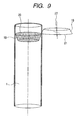
- the holding mechanism is set rotatable, and has a circular knife, inner cutting blade 18. It also has a rotary circular knife, outer cutting blade 19, on the side of outer peripheral direction of the endless metallic belt 1.
- These rotary circular knives inner cutting blade 18 and outer cutting blade 19 in pair are disposed leaving a very small gap between them in such a way that their blade faces (inner cutting blade face 20 and outer cutting blade face 21) can come into contact with each other on their side faces, and also the outer cutting blade is disposed at an angle of inclination 22 with respect to the inner cutting blade.
- These rotary circular knives set in pair were operated to cut the endless metallic belt 1.
- a silicone rubber layer (available from GE Toshiba Silicone Co., Ltd.) of 300 ⁇ m thick as the elastic layer 2 and a PFA tube (available from Gunze Sangyo, Inc.) of 20 ⁇ m thick as the toner releasing layer 3 were each layered on the endless metallic belt 1 through a primer to produce a fixing belt having the cross section as shown in Fig. 8 .
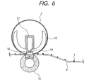
- this fixing belt 7 two belts were readied, and were used in the following running (durability) test. Stated specifically, the fixing belt 7 was set in an image heating fixing assembly as shown in Fig. 6 , to conduct the running test.
- Fig. 6 A silicone rubber layer (available from GE Toshiba Silicone Co., Ltd.) of 300 ⁇ m thick as the elastic layer 2 and a PFA tube (available from Gunze Sangyo, Inc.) of 20 ⁇ m thick as the toner releasing layer 3 were each layered on the endless metallic belt 1 through a primer to produce a fixing belt having the cross section as shown in Fig. 8 .
- reference numerals 15, 16 and 17 denote a belt guide member, a sliding plate and a pressuring rigid stay, respectively, and letter symbol t denotes a toner.
- a ceramic heater 14 at the time of fixing was set to 180°C. Unfixed toner images were fixed to a recording medium P by the aid of the heat coming from the ceramic heater and the pressure applied to a nip N.
- the fixing was performed in an intermittent mode in which it was posed for 1 second for each two-sheet continuous fixing, and the number of sheets on which each fixing belt came to crack or break was counted.
- Table 1 The results of the running test for each fixing belt are shown in Table 1.
- a fixing belt 7 used in Comparative Example 1 is shown in Fig. 10 .
- Each edge face of an endless metallic belt was worked in the same way as in Example 1 by the cutting means shown in Fig. 9 , and thereafter sanded with sand paper (#600) so as to have a plane shape.
- sand paper #600
- two fixing belts were produced in the same way as in Example 1 except that the shape of each edge face of the endless metallic belt was made flat, and the same running test as that in Example 1 was conducted. The results of the running test for each fixing belt are shown in Table 1.
- the fixing belt the endless metallic belt of which has ridges at its edge faces between the outer-surface edges and the inner-surface edges has a higher durability.
- the feature that the belt has the ridges at its edge faces makes the belt edge faces come into touch with the part that may cause a small internal stress by bending, in the portions rubbing against the end region controlling member.
- the fixing belt can be kept from coming to crack and from further cracking on as a result of its repeated bend and rubbing with the end region controlling member, and hence the fixing belt having been improved in durability can be obtained, as so considered.
Landscapes
- Physics & Mathematics (AREA)
- General Physics & Mathematics (AREA)
- Fixing For Electrophotography (AREA)
Abstract
Description
- This invention relates to an endless metallic belt, an electrophotographic endless belt, a fixing assembly, and an electrophotographic image forming apparatus.
- In an electrophotographic image forming apparatus, an endless belt is used in a fixing assembly by means of which unfixed toner images having been transferred to the surface of a recording medium such as a paper sheet is fixed by heat and pressure. As such an endless belt, an electrophotographic endless belt is known which makes use of, as a base layer, an endless metallic belt made of a metal having excellent thermal conductivity and strength as exemplified by stainless steel, nickel, aluminum or copper. In the electrophotographic image forming apparatus, the electrophotographic endless belt used in such a fixing assembly (which belt is hereinafter termed "fixing belt") is rotatingly driven by using a plurality of rollers. In that case, a force that makes the fixing belt run aside in its thrust direction (which force is hereinafter also termed "run-aside moving force") may come produced in the fixing belt being rotated. In order to control such fixing belt run-aside due to such a force, it is proposed to provide a member which controls the run-aside in the width direction of the fixing belt or provide a mechanism which detects the run-aside by using a fixing belt run-aside detecting member, to correct such run-aside. In this case, it follows that the fixing belt comes into touch with the above end region controlling member or detecting member at the former's edge face(s). On this occasion, it has come about that the fixing belt unwantedly comes to crack at its end face(s). Accordingly, in
Patent Literature 1, it is proposed to provide a lubricating grease material or a solid lubricating layer in order to improve slidability between a metallic belt edge face(s) and an end region controlling member. - PTL 1: Japanese Patent Application Laid-Open No.
2004-144833 - The present inventor has studied the invention disclosed in the
above Patent Literature 1. As the result, it has been found that, however the lubricity to the end region controlling member is improved and the slidability is improved, the fixing belt may crack as a result of its repeated bend and rubbing with the end region controlling member. Accordingly, the present inventor has recognized that, in order to make the image forming apparatus much more high-speed and highly durable, it is important to more surely prevent the fixing belt from coming to crack at its edge(s). - The present invention is directed to provide an electrophotographic endless belt that can prevent from coming to crack at its edge(s) even when it is repeatedly bend or rubed with the end region controlling member. In addition, the present invention is directed to provide an electrophotographic endless belt that can make fixing assemblies and image forming apparatus more improved in their durability. Further, the present invention is directed to provide a fixing assembly and an electrophotographic image forming apparatus which have been more improved in their durability.
- According to one aspect of the present invention, there is provided an endless metallic belt having an end region surrounded by an outer-surface edge and inner-surface edge thereof, wherein said end region hasa ridge which extends along said edges.
- According to another aspect of the present invention, there is provided an electrophotographic endless belt comprising the above endless metallic belt and a toner releasing layer.
- According to further aspect of the present invention, there is provided a fixing assembly comprising a heating member and a pressure member disposed opposingly to the heating member, wherein said heating member or said pressure member or said heating member and said pressure member has the above electrophotographic endless belt, and wherein said fixing assembly further comprises an end regioncontrolling member which is so disposed as to be able to come into contact with the ridge of the end region of the endless metallic belt.
- According to still another aspect of the present invention, there is provided an electrophotographic image forming apparatus which comprises the above electrophotographic fixing assembly.
- According to the present invention, the endless metallic belt comes into touch with the end region controlling member at the former's ridge that may cause a small internal stress by bending. Hence, it can be kept from coming to crack and from further cracking on, and brings an improvement in durability.
-
- [
Fig. 1 ]
Fig. 1 is a schematic view showing an example of the layer constitution of the fixing belt according to the present invention. - [
Fig. 2A ]
This is a view illustrating how a one-side edge of a metallic belt comes into contact with an end region controlling member.Fig. 2A is a view illustrating how a one-side edge of a conventional metallic belt comes into contact with the end region controlling member. - [
Fig. 2B ]
This is also a view illustrating how a one-side edge of a metallic belt comes into contact with an end region controlling member.Fig. 2B is a view illustrating how a one-side edge of the metallic belt according to the present invention comes into contact with the end region controlling member. - [
Fig. 3 ]
Fig. 3 is a graph showing internal stress acting at a metallic belt edge face. - [
Fig. 4A ]
Fig. 4A is a view showing an example of the edge face shape of the metallic belt in the present invention. - [
Fig. 4B ]
Fig. 4B is a view showing another example of the edge face shape of the metallic belt in the present invention. - [
Fig. 4C ]
Fig. 4C is a view showing still another example of the edge face shape of the metallic belt in the present invention. - [
Fig. 5 ]
Fig. 5 is a schematic structural view of a fixing assembly making use of ametallic belt 1 according to the present invention. - [
Fig. 6 ]
Fig. 6 is a schematic view showing an example of the construction of an image heating unit of a heat fixing system. - [
Fig. 7 ]
Fig. 7 is a detailed view of a fixing belt edge control part. - [
Fig. 8 ]
Fig. 8 is a view showing an edge face of a metallic belt in Example 1. - [
Fig. 9 ]
Fig. 9 is a schematic view showing a metallic-belt cutting means. - [
Fig. 10 ]
Fig. 10 is a view showing an edge face of a metallic belt in Comparative Example 1. - The endless metallic belt according to the present invention is described below in detail with reference to the drawings. The endless metallic belt according to the present invention is one having an end region surrounded by an outer-surface edge and an inner-surface edge, and the end region has a ridge which extends along the outer-surface edge and the inner-surface edge of the endless metallic belt.
-
Fig. 2A is an enlarged sectional view of a part at which a one-side edge of a conventional endlessmetallic belt 1 comes into touch with an endregion controlling member 4.Fig. 2B is an enlarged sectional view of a part at which a one-side edge of an endlessmetallic belt 1 according to the present invention comes into touch with the endregion controlling member 4. The endregion controlling member 4 herein termed refers to a member which controls any run-aside of the endless metallic belt toward its one edge, such as a flange or a roller. The "run-aside moving force" is produced in the endlessmetallic belt 1 in its thrust direction. Hence, the endless metallic belt is rotated in touch with the end region controlling member while being bent. This makes the endlessmetallic belt 1 receive sliding resistance from the endregion controlling member 4. An internal stress is also produced in the endlessmetallic belt 1 because of its bending at a fixing nip portion.Fig. 3 is a graph showing how the internal stress acts on the endlessmetallic belt 1 in its thickness direction when this endless belt is made to bend. As shown inFig. 3 , a tensile stress is produced on the outer peripheral side of the endless metallic belt, and a compression stress on the inner peripheral side of the endless metallic belt. Also, the internal stress comes minimal at and around the center of the endless metallic belt in its thickness direction. The more the endless metallic belt comes toward its outer periphery from the center and the vicinity thereof in its thickness direction and the more it comes toward its inner periphery therefrom, the larger the internal stress becomes. Hence, the tensile stress comes maximal at the outer-surface edge of the endless metallic belt and the compression stress comes maximal at the inner-surface edge of the endless metallic belt. - Conventionally, the edge faces of an endless metallic belt having been cut have been sanded for the purpose of removing any burrs and cracks. Accordingly, as shown in
Fig. 2A , anend region 21 surrounded by an outer-surface edge 5 and inner-surface edge 6 of the endless metallic belt stands flat. In this case, the edge face of the endless metallic belt comes into face-to-face touch with the endregion controlling member 4, and hence it receives sliding resistance therefrom at the belt outer-surface edge 5 and inner-surface edge 6 that may cause a large internal stress by bending. Hence, the endlessmetallic belt 1 tends to come to crack at the outer-surface edge 5 of the endlessmetallic belt 1 and the inner-surface edge 6 of the endlessmetallic belt 1 that have come to have a largest internal stress as a result of its repeated bend and rubbing with the endregion controlling member 4.
On the other hand, as shown inFig. 2B , in the case when the edge face of the endlessmetallic belt 1, i.e., anend region 21 surrounded by an outer-surface edge 5 and inner-surface edge 6 of the endless metallic belt is so shaped as to have aridge 23, it follows that the endless metallic belt comes into contact with the inner-surface edge at the ridge of the former. Herein, the "ridge" refers to a hill (a raised portion) that continues endlessly between the outer-surface edge and the inner-surface edge of the endless metallic belt and does outward in the width direction of the belt. Then, this ridge has tensile stress and compression stress which stand cancelled each other, to cause a small internal stress. Also, the outer-surface edge 5 and inner-surface edge 6 of the endless metallic belt that are portions having caused a large internal stress are free from any sliding resistance to be received from the endregion controlling member 4. Hence, the endless metallic belt can be well kept from coming to crack at its edge(s) when the edge face(s) of the endless metallic belt come(s) into touch with the end region controlling member(s). This enables achievement of high speed and high durability in an image forming apparatus making use of, e.g., a fixingbelt 7 the endless metallic belt of which has ridges at its edges, each extending between the outer-surface edge and the inner-surface edge of the endless metallic belt.
Figs. 4A to 4C show three embodiments of the endless metallic belt according to the present invention. More specifically, each endlessmetallic belt 1 has aridge 43 having a different shape at aregion 41 surrounded by an outer-surface edge 5 and inner-surface edge 6 of the belt. -
Fig. 1 is a sectional view of a fixing belt (electrophotographic endless belt) 7 making use of the endless metallic belt according to the present invention; being sectional in the width direction at a part on the side facing a pressure roller. The fixingbelt 7 is a layered member consisting essentially of an endlessmetallic belt 1 according to the present invention, anelastic layer 2 and atoner releasing layer 3. - The endless
metallic belt 1 contains stainless steel (SUS), or nickel, aluminum, copper or an alloy of any of these, having superior heat resistance and thermal conductivity. The endlessmetallic belt 1 may preferably have a total thickness of from 20 µm or more to 200 µm or less. - The
elastic layer 2 may be provided or need not be provided. By providing theelastic layer 2, toner images to be heated can be covered at the fixing nip to ensure the conduction of heat thereat, and also the restoring force of the endlessmetallic belt 1 can be supplemented to relieve any fatigue due to its rotation and bend. Also, by providing theelastic layer 2, the surface of the fixing belt release layer can be improved in its close contact with the surfaces of unfixed toner images to enable conduction of heat in a good efficiency. The fixingbelt 7 provided with theelastic layer 2 is suitable especially for the heat-fixing of color toner images having a large unfixed-toner-on level. - The
elastic layer 2 may be made of any material without any particular limitations. Materials having a good heat resistance and a good thermal conductivity may be selected. Theelastic layer 2 may preferably contain at least one selected from silicone rubber, fluorine rubber and fluorosilicone rubber, and silicone rubber is particularly preferred. Specific examples of the material that forms theelastic layer 2 are shown below. They are polydimethylsiloxane, polymethyltrifluoro-propylsiloxane, polymethylvinylsiloxane, polytrifluoro-propylvinylsiloxane, polymethylphenylsiloxane, polyphenylvinylsiloxane, copolymers of any of these polysilozxanes, and so forth. - The elastic layer may optionally be incorporated with silica, calcium carbonate, quartz powder, zirconium silicate, clay (aluminum silicate), talc (hydrous magnesium silicate), alumina (aluminum oxide), red iron oxide (ferric oxide) or the like.
- The
elastic layer 2 may preferably have a thickness of from 10 µm or more to 1,000 µm or less, and much preferably from 50 µm or more to 500 µm or less, because a good fixed-image quality can be achieved. Where color images, in particular, photographic images are printed, solid images are formed over a large area on a recording medium P. In such a case, heating non-uniformity may come about unless the heating surface (release layer 3) can follow up unevenness of the recording medium or unevenness of toner layers, to cause gloss non-uniformity in images between areas having a high rate of heat transfer and areas having a low rate of heat transfer. That is, glossiness comes high at the areas having a high rate of heat transfer and glossiness comes low at the areas having a low rate of heat transfer. If theelastic layer 2 has too small thickness, the heating surface can not follow up any uneven surface profile of the recording medium or toner layers in some cases to cause gloss non-uniformity in images. If on the other hand theelastic layer 2 has too large thickness, theelastic layer 2 may have so high heat resistance and so large heat capacity as to make it difficult to achieve quick start. - The
elastic layer 2 may preferably have a hardness (JIS K 6301) of from 3° or more to 60° or less, and much preferably from 5° or more to 45° or less, because the image gloss non-uniformity can sufficiently be kept from coming about and good fixed-image quality can be achieved. - The
elastic layer 2 may preferably have a thermal conductivity A of from 3.3×10⁻¹ (W/m·K) or more to 8.4×10⁻¹ (W/m·K) or less. - Such an
elastic layer 2 may be formed by any of methods as shown in the following a) to d). - a) A method in which a
metallic layer 1 is coated thereon with a material such as liquid silicone rubber by a means such as blade coating, followed by heat curing; - b) a method in which the material such as liquid silicone rubber is casted into a mold, followed by vulcanization curing;
- c) a method in which the material is shaped by extrusion, followed by vulcanization curing; and
- d) a method in which the material is injection-molded, followed by vulcanization curing.
- Materials for the
toner releasing layer 3 are exemplified below. They are fluorine resins such as PFA (tetrafluoroethylene/perfluoroalkyl ether copolymer), PTFE (polytetrafluoroethylene) and FEP
(tetrafluoroethylene/hexafluoropropylene copolymer), silicone resins, fluorosilicone rubbers, fluorine rubbers and silicone rubbers. In particular, PFA is preferred because the toner and so forth can not easily adhere to the toner releasing layer. The toner releasing layer may optionally be incorporated with a conducting agent such as carbon black or tin oxide. Thetoner releasing layer 3 may have a thickness of from 1 µm or more to 100 µm or less as a standard. - Such a
toner releasing layer 3 may be formed by a known method. For example, in the case of a fluorine resin type material, it may be formed by a method in which the endlessmetallic belt 1 or theelastic layer 2 is coated thereon with a coating material prepared by dispersing a fluorine resin powder, followed by drying or baking, or by a method in which it is covered thereon with a film beforehand made into a tube and the former is bonded to the latter. In the case of a rubber type material, the toner releasing layer may be formed by a method in which a liquid material is casted into a mold, followed by vulcanization curing, a method in which the material is shaped by extrusion, followed by vulcanization curing, or a method in which the material is injection-molded, followed by vulcanization curing. -
Fig. 5 is a sectional view in the axial direction of a fixing assembly for the electrophotographic image forming apparatus, making use of the endless metallic belt according to the present invention in the fixing belt.
A heater (heating member) 8 is a ceramic heater or the like making use of alumina or aluminum nitride in its substrate. A heat-insulating stay holder 9 holds theheater 8 on the bottom surface side of the holder, and a fixingbelt 7 is fitted to the heat-insulating stay holder 9 at the former's right and left both ends, and is provided with an endregion controlling member 4 on each side, which is touchable with each edge face ridge portion of the fixing belt.
The endregion controlling member 4 is a member which controls any run-aside of the electrophotographic endless belt in its width direction during its travel. The endregion controlling member 4 is of an outer receiving die having on each side aspring seat 4a provided in an outward integrally projected form and a incomplete annular shapedguard part 4b provided in an inward integrally projected form.Reference numeral 10 denotes a heat-resistant elastic pressure roller serving as a pressure member. Thepressure roller 10 consists essentially of amandrel 11 and anelastic layer 2, and is rotatably held by bearings on both end portions of themandrel 11 and between right and left side plates of a chassis (not shown) of the assembly.Reference numeral 12 denotes a pressure roller rotating drive gear secured to the pressure roller mandrel on its one end side. The fixingbelt 7 is disposed on the upper side of thepressure roller 10 and oppositely to thepressure roller 10 with theheater 8 side downward.
Then, the fixingbelt 7 is kept in uniform pressure contact with thepressure roller 10 by pressing down eachspring seat 4a of each endregion controlling member 4 of the right and left both sides by means of eachpressure spring 13 at a stated pressure. Thus, the bottom surface of theheater 8 is brought into pressure contact with the top surface of thepressure roller 10, holding the fixingbelt 7 between them, so that a fixing nip zone N is formed in a stated width between the fixingbelt 7 and thepressure roller 10.
The fixingbelt 7 receives the run-aside moving force in its thrust direction when it is rotatingly driven, because of, e.g., any scatter of precision of component parts and any non-uniform temperature distribution in the lengthwise direction of theceramic heater 14, and it moves in any of the right and left directions. In order to control such run-aside in the thrust direction, it is necessary for the assembly to be so set up as to control the run-aside in such a state that the edge faces of the fixingbelt 7 run against end region controlling members such as flanges.
The endregion controlling member 4 is a controlling member for that purpose. Here, even where the fixingbelt 7 is follow-up rotated with the rotation of thepressure roller 10 and has run aside in the thrust direction, such run-aside is so controlled that the ridge of the left side edge face or right side edge face of the fixingbelt 7 may come into touch with the inner wall face of the endregion controlling member 4. Then, the belt outer-surface edge 5 and inner-surface edge 6 that have a large internal stress do not come into touch with the endregion controlling member 4, and hence do not receive any sliding resistance therefrom. As the result, the fixingbelt 7 can be better kept from coming to crack at its edges. - A fixing
belt 7 used in Example 1 is shown inFig. 8 . The fixingbelt 7 consists essentially of an endlessmetallic belt 1 and provided thereon in layers anelastic layer 2 and atoner releasing layer 3. The endlessmetallic belt 1 was made of stainless steel (SUS), and had an inner diameter of 24 mm, a wall thickness of 30 µm and a length of 240 mm. As shown inFig. 8 , each edge face of the endless metallic belt was worked by a cutting means in such a shape that it had a ridge between a outer-surface edge 5 and a inner-surface edge 6 of the belt, and was made into a raised form of 10 µm in height H in the lengthwise direction at the central position of the wall thickness.
As the cutting means therefor, it is described with reference toFig. 9 . The endlessmetallic belt 1 is fixedly held on its inside with a holding mechanism (not shown). The holding mechanism is set rotatable, and has a circular knife,inner cutting blade 18. It also has a rotary circular knife,outer cutting blade 19, on the side of outer peripheral direction of the endlessmetallic belt 1. These rotary circular knivesinner cutting blade 18 andouter cutting blade 19 in pair are disposed leaving a very small gap between them in such a way that their blade faces (innercutting blade face 20 and outer cutting blade face 21) can come into contact with each other on their side faces, and also the outer cutting blade is disposed at an angle ofinclination 22 with respect to the inner cutting blade. These rotary circular knives set in pair were operated to cut the endlessmetallic belt 1. - A silicone rubber layer (available from GE Toshiba Silicone Co., Ltd.) of 300 µm thick as the
elastic layer 2 and a PFA tube (available from Gunze Sangyo, Inc.) of 20 µm thick as thetoner releasing layer 3 were each layered on the endlessmetallic belt 1 through a primer to produce a fixing belt having the cross section as shown inFig. 8 . For this fixingbelt 7, two belts were readied, and were used in the following running (durability) test.
Stated specifically, the fixingbelt 7 was set in an image heating fixing assembly as shown inFig. 6 , to conduct the running test. InFig. 6 ,reference numerals ceramic heater 14 at the time of fixing was set to 180°C. Unfixed toner images were fixed to a recording medium P by the aid of the heat coming from the ceramic heater and the pressure applied to a nip N. The fixing was performed in an intermittent mode in which it was posed for 1 second for each two-sheet continuous fixing, and the number of sheets on which each fixing belt came to crack or break was counted. The results of the running test for each fixing belt are shown in Table 1. - A fixing
belt 7 used in Comparative Example 1 is shown inFig. 10 . Each edge face of an endless metallic belt was worked in the same way as in Example 1 by the cutting means shown inFig. 9 , and thereafter sanded with sand paper (#600) so as to have a plane shape. In this Comparative Example, two fixing belts were produced in the same way as in Example 1 except that the shape of each edge face of the endless metallic belt was made flat, and the same running test as that in Example 1 was conducted. The results of the running test for each fixing belt are shown in Table 1. -
Table 1 Number of sheets for running (sheets) Example 1 408×103 415×103 Comparative Example 1 270×103 294×103 - From the results shown above, it is seen that the fixing belt the endless metallic belt of which has ridges at its edge faces between the outer-surface edges and the inner-surface edges has a higher durability. This is because the feature that the belt has the ridges at its edge faces makes the belt edge faces come into touch with the part that may cause a small internal stress by bending, in the portions rubbing against the end region controlling member. Hence, the fixing belt can be kept from coming to crack and from further cracking on as a result of its repeated bend and rubbing with the end region controlling member, and hence the fixing belt having been improved in durability can be obtained, as so considered.
- This application claims priority from Japanese Patent Application No.
2009-227333, filed on September 30, 2009
Claims (4)
- An endless metallic belt having an end region surrounded by an outer-surface edge and inner-surface edge thereof, wherein
said end region has a ridge extending along said edges. - An electrophotographic endless belt which comprises the endless metallic belt according to claim 1, and a toner releasing layer.
- An electrophotographic fixing assembly comprising a heating member and a pressure member disposed opposingly to said heating member, wherein
at least one member selected from the group consisting of said heating member and said pressure member comprises said electrophotographic endless belt according to claim 2, and wherein
said fixing assembly further comprises an end region controlling member which is so disposed as to be able to come into contact with said ridge of the end region of said endless metallic belt. - An electrophotographic image forming apparatus which comprises said electrophotographic fixing assembly according to claim 3.
Applications Claiming Priority (2)
| Application Number | Priority Date | Filing Date | Title |
|---|---|---|---|
| JP2009227333 | 2009-09-30 | ||
| PCT/JP2010/005734 WO2011039975A1 (en) | 2009-09-30 | 2010-09-22 | Endless metal belt, endless belt for use in electrophotography, fixing device, and electrophotographic image-forming device |
Publications (3)
| Publication Number | Publication Date |
|---|---|
| EP2453313A1 true EP2453313A1 (en) | 2012-05-16 |
| EP2453313A4 EP2453313A4 (en) | 2017-05-10 |
| EP2453313B1 EP2453313B1 (en) | 2019-08-21 |
Family
ID=43825827
Family Applications (1)
| Application Number | Title | Priority Date | Filing Date |
|---|---|---|---|
| EP10820100.5A Active EP2453313B1 (en) | 2009-09-30 | 2010-09-22 | Endless metal belt, endless belt for use in electrophotography, fixing device, and electrophotographic image-forming device |
Country Status (6)
| Country | Link |
|---|---|
| US (1) | US8190075B2 (en) |
| EP (1) | EP2453313B1 (en) |
| JP (1) | JP4701316B2 (en) |
| KR (1) | KR101427492B1 (en) |
| CN (1) | CN102576206B (en) |
| WO (1) | WO2011039975A1 (en) |
Families Citing this family (5)
| Publication number | Priority date | Publication date | Assignee | Title |
|---|---|---|---|---|
| JP5924915B2 (en) * | 2011-12-01 | 2016-05-25 | キヤノン株式会社 | Heating apparatus and image forming apparatus |
| JP5966451B2 (en) * | 2012-03-06 | 2016-08-10 | 株式会社リコー | Fixing apparatus and image forming apparatus |
| JP6094061B2 (en) * | 2012-05-31 | 2017-03-15 | ブラザー工業株式会社 | Fixing device and manufacturing method thereof |
| US10185259B2 (en) * | 2016-03-18 | 2019-01-22 | Ricoh Company, Ltd. | Endless belt, fixing device, image forming apparatus, and method of manufacturing endless belt |
| JP6870333B2 (en) * | 2016-03-18 | 2021-05-12 | 株式会社リコー | Endless belt, fixing device, image forming device, and manufacturing method of endless belt |
Family Cites Families (18)
| Publication number | Priority date | Publication date | Assignee | Title |
|---|---|---|---|---|
| US4043658A (en) * | 1969-09-25 | 1977-08-23 | Canon Kabushiki Kaisha | Electrophotographic photosensitive member |
| US4952293A (en) * | 1989-12-29 | 1990-08-28 | Xerox Corporation | Polymer electrodeposition process |
| JP3033029B2 (en) * | 1990-08-07 | 2000-04-17 | 株式会社リコー | Photoreceptor belt for electrophotographic devices |
| JPH10228192A (en) * | 1997-02-15 | 1998-08-25 | Canon Inc | Heating film, heating device and image forming device |
| JP3534033B2 (en) * | 2000-02-29 | 2004-06-07 | 日産自動車株式会社 | Laminated metal belt ring and manufacturing method thereof |
| JP4151204B2 (en) * | 2000-07-19 | 2008-09-17 | コニカミノルタビジネステクノロジーズ株式会社 | Fixing belt and belt fixing device |
| JP2004144833A (en) | 2002-10-22 | 2004-05-20 | Canon Inc | Heating equipment |
| CN1497394A (en) | 2002-10-22 | 2004-05-19 | 佳能株式会社 | Image heating device |
| US7413496B2 (en) * | 2003-02-10 | 2008-08-19 | Honda Motor Co., Ltd. | Method and device for polishing endless belt metal rings for continuously variable transmission |
| JP3981069B2 (en) * | 2003-12-26 | 2007-09-26 | 本田技研工業株式会社 | Metal belt for continuously variable transmission, metal ring manufacturing method, and metal ring shape measuring method |
| JP4280664B2 (en) * | 2004-03-31 | 2009-06-17 | キヤノン株式会社 | Image heating device |
| CN100468226C (en) | 2004-04-26 | 2009-03-11 | 佳能株式会社 | Fixing method and fixing device |
| CN101046667A (en) * | 2006-03-13 | 2007-10-03 | 株式会社理光 | Fixing device and image forming apparatus including the same |
| US7603068B2 (en) * | 2006-05-03 | 2009-10-13 | Kabushiki Kaisha Toshiba | Fixing apparatus for forming an image |
| KR20080003542A (en) * | 2006-07-03 | 2008-01-08 | 삼성전자주식회사 | Fixture of Electrophotographic Image Forming Device |
| JP4887337B2 (en) | 2008-03-21 | 2012-02-29 | 廖建華 | Storage bag that can be exhausted from porous |
| JP2009237185A (en) * | 2008-03-27 | 2009-10-15 | Seiko Epson Corp | Fixing device and image forming apparatus |
| JP5366427B2 (en) * | 2008-04-09 | 2013-12-11 | キヤノン株式会社 | Film and image heating apparatus provided with the film |
-
2010
- 2010-09-22 CN CN201080043920.1A patent/CN102576206B/en active Active
- 2010-09-22 WO PCT/JP2010/005734 patent/WO2011039975A1/en not_active Ceased
- 2010-09-22 EP EP10820100.5A patent/EP2453313B1/en active Active
- 2010-09-22 KR KR1020127010168A patent/KR101427492B1/en not_active Expired - Fee Related
- 2010-09-30 JP JP2010221415A patent/JP4701316B2/en active Active
- 2010-12-02 US US12/958,683 patent/US8190075B2/en active Active
Also Published As
| Publication number | Publication date |
|---|---|
| EP2453313A4 (en) | 2017-05-10 |
| KR101427492B1 (en) | 2014-08-07 |
| JP2011095735A (en) | 2011-05-12 |
| WO2011039975A1 (en) | 2011-04-07 |
| EP2453313B1 (en) | 2019-08-21 |
| CN102576206B (en) | 2015-01-07 |
| US8190075B2 (en) | 2012-05-29 |
| US20110081174A1 (en) | 2011-04-07 |
| JP4701316B2 (en) | 2011-06-15 |
| CN102576206A (en) | 2012-07-11 |
| KR20120056881A (en) | 2012-06-04 |
Similar Documents
| Publication | Publication Date | Title |
|---|---|---|
| JP4529579B2 (en) | Fixing device | |
| EP2453313B1 (en) | Endless metal belt, endless belt for use in electrophotography, fixing device, and electrophotographic image-forming device | |
| US10877412B2 (en) | Fixing device | |
| CN102012663A (en) | Fixing device and image forming apparatus incorporating same | |
| JP2005003969A (en) | Sliding member, fixing device, and manufacturing method of sliding member | |
| JP5450930B2 (en) | Image heating device | |
| JP5569143B2 (en) | Fixing belt, fixing device, and image forming apparatus | |
| JP2009045577A (en) | Fluorine resin film forming method and film forming product thereof | |
| JP2011075816A (en) | Endless fixing belt and thermally fixing device | |
| US7171150B2 (en) | Belt-type fixing device | |
| JP7151467B2 (en) | Fixing device and image forming device | |
| JP2005221712A (en) | Image fixing device | |
| JP7731720B2 (en) | Fixing member and heat fixing device | |
| JP2010128429A (en) | Image heating device and heating rotating member used for the same | |
| JP2019028182A (en) | Fixing belt and fixing device | |
| US12072650B2 (en) | Image heating device and image forming apparatus | |
| JP4850738B2 (en) | Evaluation method of fixing roller | |
| JPH04125675A (en) | Fixing device | |
| JP2020106560A (en) | Rotating device, fixing device, and image forming device | |
| JP6238821B2 (en) | FIXING MEMBER, ITS MANUFACTURING METHOD, AND FIXING DEVICE | |
| JP2004286932A (en) | Belt fixing device | |
| JP2018205402A (en) | Fixing device | |
| JP2006267436A (en) | Belt for fixing and belt fixing device using it | |
| JP2006138944A (en) | Fixing member and fixing device | |
| JP2024000979A (en) | Fixing film and method for manufacturing the same, heat fixing device, and electrophotographic image forming apparatus |
Legal Events
| Date | Code | Title | Description |
|---|---|---|---|
| PUAI | Public reference made under article 153(3) epc to a published international application that has entered the european phase |
Free format text: ORIGINAL CODE: 0009012 |
|
| 17P | Request for examination filed |
Effective date: 20120210 |
|
| AK | Designated contracting states |
Kind code of ref document: A1 Designated state(s): AL AT BE BG CH CY CZ DE DK EE ES FI FR GB GR HR HU IE IS IT LI LT LU LV MC MK MT NL NO PL PT RO SE SI SK SM TR |
|
| DAX | Request for extension of the european patent (deleted) | ||
| RA4 | Supplementary search report drawn up and despatched (corrected) |
Effective date: 20170407 |
|
| RIC1 | Information provided on ipc code assigned before grant |
Ipc: G03G 15/20 20060101AFI20170403BHEP |
|
| STAA | Information on the status of an ep patent application or granted ep patent |
Free format text: STATUS: EXAMINATION IS IN PROGRESS |
|
| 17Q | First examination report despatched |
Effective date: 20190221 |
|
| GRAP | Despatch of communication of intention to grant a patent |
Free format text: ORIGINAL CODE: EPIDOSNIGR1 |
|
| STAA | Information on the status of an ep patent application or granted ep patent |
Free format text: STATUS: GRANT OF PATENT IS INTENDED |
|
| INTG | Intention to grant announced |
Effective date: 20190522 |
|
| GRAS | Grant fee paid |
Free format text: ORIGINAL CODE: EPIDOSNIGR3 |
|
| GRAA | (expected) grant |
Free format text: ORIGINAL CODE: 0009210 |
|
| STAA | Information on the status of an ep patent application or granted ep patent |
Free format text: STATUS: THE PATENT HAS BEEN GRANTED |
|
| AK | Designated contracting states |
Kind code of ref document: B1 Designated state(s): AL AT BE BG CH CY CZ DE DK EE ES FI FR GB GR HR HU IE IS IT LI LT LU LV MC MK MT NL NO PL PT RO SE SI SK SM TR |
|
| REG | Reference to a national code |
Ref country code: GB Ref legal event code: FG4D |
|
| REG | Reference to a national code |
Ref country code: CH Ref legal event code: EP |
|
| REG | Reference to a national code |
Ref country code: DE Ref legal event code: R096 Ref document number: 602010060700 Country of ref document: DE |
|
| REG | Reference to a national code |
Ref country code: AT Ref legal event code: REF Ref document number: 1170442 Country of ref document: AT Kind code of ref document: T Effective date: 20190915 |
|
| REG | Reference to a national code |
Ref country code: IE Ref legal event code: FG4D |
|
| REG | Reference to a national code |
Ref country code: LT Ref legal event code: MG4D |
|
| REG | Reference to a national code |
Ref country code: NL Ref legal event code: MP Effective date: 20190821 |
|
| PG25 | Lapsed in a contracting state [announced via postgrant information from national office to epo] |
Ref country code: SE Free format text: LAPSE BECAUSE OF FAILURE TO SUBMIT A TRANSLATION OF THE DESCRIPTION OR TO PAY THE FEE WITHIN THE PRESCRIBED TIME-LIMIT Effective date: 20190821 Ref country code: NL Free format text: LAPSE BECAUSE OF FAILURE TO SUBMIT A TRANSLATION OF THE DESCRIPTION OR TO PAY THE FEE WITHIN THE PRESCRIBED TIME-LIMIT Effective date: 20190821 Ref country code: HR Free format text: LAPSE BECAUSE OF FAILURE TO SUBMIT A TRANSLATION OF THE DESCRIPTION OR TO PAY THE FEE WITHIN THE PRESCRIBED TIME-LIMIT Effective date: 20190821 Ref country code: NO Free format text: LAPSE BECAUSE OF FAILURE TO SUBMIT A TRANSLATION OF THE DESCRIPTION OR TO PAY THE FEE WITHIN THE PRESCRIBED TIME-LIMIT Effective date: 20191121 Ref country code: LT Free format text: LAPSE BECAUSE OF FAILURE TO SUBMIT A TRANSLATION OF THE DESCRIPTION OR TO PAY THE FEE WITHIN THE PRESCRIBED TIME-LIMIT Effective date: 20190821 Ref country code: BG Free format text: LAPSE BECAUSE OF FAILURE TO SUBMIT A TRANSLATION OF THE DESCRIPTION OR TO PAY THE FEE WITHIN THE PRESCRIBED TIME-LIMIT Effective date: 20191121 Ref country code: PT Free format text: LAPSE BECAUSE OF FAILURE TO SUBMIT A TRANSLATION OF THE DESCRIPTION OR TO PAY THE FEE WITHIN THE PRESCRIBED TIME-LIMIT Effective date: 20191223 Ref country code: FI Free format text: LAPSE BECAUSE OF FAILURE TO SUBMIT A TRANSLATION OF THE DESCRIPTION OR TO PAY THE FEE WITHIN THE PRESCRIBED TIME-LIMIT Effective date: 20190821 |
|
| PG25 | Lapsed in a contracting state [announced via postgrant information from national office to epo] |
Ref country code: LV Free format text: LAPSE BECAUSE OF FAILURE TO SUBMIT A TRANSLATION OF THE DESCRIPTION OR TO PAY THE FEE WITHIN THE PRESCRIBED TIME-LIMIT Effective date: 20190821 Ref country code: GR Free format text: LAPSE BECAUSE OF FAILURE TO SUBMIT A TRANSLATION OF THE DESCRIPTION OR TO PAY THE FEE WITHIN THE PRESCRIBED TIME-LIMIT Effective date: 20191122 Ref country code: ES Free format text: LAPSE BECAUSE OF FAILURE TO SUBMIT A TRANSLATION OF THE DESCRIPTION OR TO PAY THE FEE WITHIN THE PRESCRIBED TIME-LIMIT Effective date: 20190821 Ref country code: IS Free format text: LAPSE BECAUSE OF FAILURE TO SUBMIT A TRANSLATION OF THE DESCRIPTION OR TO PAY THE FEE WITHIN THE PRESCRIBED TIME-LIMIT Effective date: 20191221 Ref country code: AL Free format text: LAPSE BECAUSE OF FAILURE TO SUBMIT A TRANSLATION OF THE DESCRIPTION OR TO PAY THE FEE WITHIN THE PRESCRIBED TIME-LIMIT Effective date: 20190821 |
|
| REG | Reference to a national code |
Ref country code: AT Ref legal event code: MK05 Ref document number: 1170442 Country of ref document: AT Kind code of ref document: T Effective date: 20190821 |
|
| PG25 | Lapsed in a contracting state [announced via postgrant information from national office to epo] |
Ref country code: TR Free format text: LAPSE BECAUSE OF FAILURE TO SUBMIT A TRANSLATION OF THE DESCRIPTION OR TO PAY THE FEE WITHIN THE PRESCRIBED TIME-LIMIT Effective date: 20190821 |
|
| PG25 | Lapsed in a contracting state [announced via postgrant information from national office to epo] |
Ref country code: AT Free format text: LAPSE BECAUSE OF FAILURE TO SUBMIT A TRANSLATION OF THE DESCRIPTION OR TO PAY THE FEE WITHIN THE PRESCRIBED TIME-LIMIT Effective date: 20190821 Ref country code: EE Free format text: LAPSE BECAUSE OF FAILURE TO SUBMIT A TRANSLATION OF THE DESCRIPTION OR TO PAY THE FEE WITHIN THE PRESCRIBED TIME-LIMIT Effective date: 20190821 Ref country code: IT Free format text: LAPSE BECAUSE OF FAILURE TO SUBMIT A TRANSLATION OF THE DESCRIPTION OR TO PAY THE FEE WITHIN THE PRESCRIBED TIME-LIMIT Effective date: 20190821 Ref country code: DK Free format text: LAPSE BECAUSE OF FAILURE TO SUBMIT A TRANSLATION OF THE DESCRIPTION OR TO PAY THE FEE WITHIN THE PRESCRIBED TIME-LIMIT Effective date: 20190821 Ref country code: RO Free format text: LAPSE BECAUSE OF FAILURE TO SUBMIT A TRANSLATION OF THE DESCRIPTION OR TO PAY THE FEE WITHIN THE PRESCRIBED TIME-LIMIT Effective date: 20190821 Ref country code: PL Free format text: LAPSE BECAUSE OF FAILURE TO SUBMIT A TRANSLATION OF THE DESCRIPTION OR TO PAY THE FEE WITHIN THE PRESCRIBED TIME-LIMIT Effective date: 20190821 |
|
| PG25 | Lapsed in a contracting state [announced via postgrant information from national office to epo] |
Ref country code: IS Free format text: LAPSE BECAUSE OF FAILURE TO SUBMIT A TRANSLATION OF THE DESCRIPTION OR TO PAY THE FEE WITHIN THE PRESCRIBED TIME-LIMIT Effective date: 20200224 Ref country code: MC Free format text: LAPSE BECAUSE OF FAILURE TO SUBMIT A TRANSLATION OF THE DESCRIPTION OR TO PAY THE FEE WITHIN THE PRESCRIBED TIME-LIMIT Effective date: 20190821 Ref country code: SK Free format text: LAPSE BECAUSE OF FAILURE TO SUBMIT A TRANSLATION OF THE DESCRIPTION OR TO PAY THE FEE WITHIN THE PRESCRIBED TIME-LIMIT Effective date: 20190821 Ref country code: CZ Free format text: LAPSE BECAUSE OF FAILURE TO SUBMIT A TRANSLATION OF THE DESCRIPTION OR TO PAY THE FEE WITHIN THE PRESCRIBED TIME-LIMIT Effective date: 20190821 Ref country code: SM Free format text: LAPSE BECAUSE OF FAILURE TO SUBMIT A TRANSLATION OF THE DESCRIPTION OR TO PAY THE FEE WITHIN THE PRESCRIBED TIME-LIMIT Effective date: 20190821 |
|
| REG | Reference to a national code |
Ref country code: CH Ref legal event code: PL |
|
| REG | Reference to a national code |
Ref country code: DE Ref legal event code: R097 Ref document number: 602010060700 Country of ref document: DE |
|
| PLBE | No opposition filed within time limit |
Free format text: ORIGINAL CODE: 0009261 |
|
| STAA | Information on the status of an ep patent application or granted ep patent |
Free format text: STATUS: NO OPPOSITION FILED WITHIN TIME LIMIT |
|
| PG2D | Information on lapse in contracting state deleted |
Ref country code: IS |
|
| PG25 | Lapsed in a contracting state [announced via postgrant information from national office to epo] |
Ref country code: LU Free format text: LAPSE BECAUSE OF NON-PAYMENT OF DUE FEES Effective date: 20190922 Ref country code: CH Free format text: LAPSE BECAUSE OF NON-PAYMENT OF DUE FEES Effective date: 20190930 Ref country code: IE Free format text: LAPSE BECAUSE OF NON-PAYMENT OF DUE FEES Effective date: 20190922 Ref country code: LI Free format text: LAPSE BECAUSE OF NON-PAYMENT OF DUE FEES Effective date: 20190930 |
|
| 26N | No opposition filed |
Effective date: 20200603 |
|
| REG | Reference to a national code |
Ref country code: BE Ref legal event code: MM Effective date: 20190930 |
|
| PG25 | Lapsed in a contracting state [announced via postgrant information from national office to epo] |
Ref country code: SI Free format text: LAPSE BECAUSE OF FAILURE TO SUBMIT A TRANSLATION OF THE DESCRIPTION OR TO PAY THE FEE WITHIN THE PRESCRIBED TIME-LIMIT Effective date: 20190821 Ref country code: BE Free format text: LAPSE BECAUSE OF NON-PAYMENT OF DUE FEES Effective date: 20190930 |
|
| GBPC | Gb: european patent ceased through non-payment of renewal fee |
Effective date: 20191121 |
|
| PG25 | Lapsed in a contracting state [announced via postgrant information from national office to epo] |
Ref country code: FR Free format text: LAPSE BECAUSE OF NON-PAYMENT OF DUE FEES Effective date: 20191021 Ref country code: GB Free format text: LAPSE BECAUSE OF NON-PAYMENT OF DUE FEES Effective date: 20191121 |
|
| PG25 | Lapsed in a contracting state [announced via postgrant information from national office to epo] |
Ref country code: CY Free format text: LAPSE BECAUSE OF FAILURE TO SUBMIT A TRANSLATION OF THE DESCRIPTION OR TO PAY THE FEE WITHIN THE PRESCRIBED TIME-LIMIT Effective date: 20190821 |
|
| PG25 | Lapsed in a contracting state [announced via postgrant information from national office to epo] |
Ref country code: MT Free format text: LAPSE BECAUSE OF FAILURE TO SUBMIT A TRANSLATION OF THE DESCRIPTION OR TO PAY THE FEE WITHIN THE PRESCRIBED TIME-LIMIT Effective date: 20190821 Ref country code: HU Free format text: LAPSE BECAUSE OF FAILURE TO SUBMIT A TRANSLATION OF THE DESCRIPTION OR TO PAY THE FEE WITHIN THE PRESCRIBED TIME-LIMIT; INVALID AB INITIO Effective date: 20100922 |
|
| PG25 | Lapsed in a contracting state [announced via postgrant information from national office to epo] |
Ref country code: MK Free format text: LAPSE BECAUSE OF FAILURE TO SUBMIT A TRANSLATION OF THE DESCRIPTION OR TO PAY THE FEE WITHIN THE PRESCRIBED TIME-LIMIT Effective date: 20190821 |
|
| PGFP | Annual fee paid to national office [announced via postgrant information from national office to epo] |
Ref country code: DE Payment date: 20250820 Year of fee payment: 16 |