EP2453194A1 - Abwasserkanal ausgerüstet mit einem Wärmetauscher, und Duschwanne ausgerüstet mit solch einem Abwasserkanal - Google Patents
Abwasserkanal ausgerüstet mit einem Wärmetauscher, und Duschwanne ausgerüstet mit solch einem Abwasserkanal Download PDFInfo
- Publication number
- EP2453194A1 EP2453194A1 EP11189335A EP11189335A EP2453194A1 EP 2453194 A1 EP2453194 A1 EP 2453194A1 EP 11189335 A EP11189335 A EP 11189335A EP 11189335 A EP11189335 A EP 11189335A EP 2453194 A1 EP2453194 A1 EP 2453194A1
- Authority
- EP
- European Patent Office
- Prior art keywords
- tube
- drain channel
- cover
- heat exchanger
- drain
- Prior art date
- Legal status (The legal status is an assumption and is not a legal conclusion. Google has not performed a legal analysis and makes no representation as to the accuracy of the status listed.)
- Granted
Links
- XLYOFNOQVPJJNP-UHFFFAOYSA-N water Substances O XLYOFNOQVPJJNP-UHFFFAOYSA-N 0.000 claims abstract description 53
- 238000005406 washing Methods 0.000 claims abstract description 24
- 239000002184 metal Substances 0.000 claims abstract description 17
- 229910052751 metal Inorganic materials 0.000 claims abstract description 17
- 238000004804 winding Methods 0.000 claims description 10
- 230000002349 favourable effect Effects 0.000 description 5
- DNJIEGIFACGWOD-UHFFFAOYSA-N ethanethiol Chemical compound CCS DNJIEGIFACGWOD-UHFFFAOYSA-N 0.000 description 3
- 241000589248 Legionella Species 0.000 description 2
- 238000010438 heat treatment Methods 0.000 description 2
- RYGMFSIKBFXOCR-UHFFFAOYSA-N Copper Chemical compound [Cu] RYGMFSIKBFXOCR-UHFFFAOYSA-N 0.000 description 1
- 230000004308 accommodation Effects 0.000 description 1
- 230000001680 brushing effect Effects 0.000 description 1
- 238000011109 contamination Methods 0.000 description 1
- 229910052802 copper Inorganic materials 0.000 description 1
- 239000010949 copper Substances 0.000 description 1
- 230000008878 coupling Effects 0.000 description 1
- 238000010168 coupling process Methods 0.000 description 1
- 238000005859 coupling reaction Methods 0.000 description 1
- 229920002457 flexible plastic Polymers 0.000 description 1
- 239000012466 permeate Substances 0.000 description 1
- 229920003023 plastic Polymers 0.000 description 1
- 229910001220 stainless steel Inorganic materials 0.000 description 1
- 239000010935 stainless steel Substances 0.000 description 1
Images


Classifications
-
- F—MECHANICAL ENGINEERING; LIGHTING; HEATING; WEAPONS; BLASTING
- F28—HEAT EXCHANGE IN GENERAL
- F28D—HEAT-EXCHANGE APPARATUS, NOT PROVIDED FOR IN ANOTHER SUBCLASS, IN WHICH THE HEAT-EXCHANGE MEDIA DO NOT COME INTO DIRECT CONTACT
- F28D7/00—Heat-exchange apparatus having stationary tubular conduit assemblies for both heat-exchange media, the media being in contact with different sides of a conduit wall
- F28D7/02—Heat-exchange apparatus having stationary tubular conduit assemblies for both heat-exchange media, the media being in contact with different sides of a conduit wall the conduits being helically coiled
- F28D7/024—Heat-exchange apparatus having stationary tubular conduit assemblies for both heat-exchange media, the media being in contact with different sides of a conduit wall the conduits being helically coiled the conduits of only one medium being helically coiled tubes, the coils having a cylindrical configuration
-
- F—MECHANICAL ENGINEERING; LIGHTING; HEATING; WEAPONS; BLASTING
- F24—HEATING; RANGES; VENTILATING
- F24D—DOMESTIC- OR SPACE-HEATING SYSTEMS, e.g. CENTRAL HEATING SYSTEMS; DOMESTIC HOT-WATER SUPPLY SYSTEMS; ELEMENTS OR COMPONENTS THEREFOR
- F24D17/00—Domestic hot-water supply systems
- F24D17/0005—Domestic hot-water supply systems using recuperation of waste heat
-
- F—MECHANICAL ENGINEERING; LIGHTING; HEATING; WEAPONS; BLASTING
- F24—HEATING; RANGES; VENTILATING
- F24D—DOMESTIC- OR SPACE-HEATING SYSTEMS, e.g. CENTRAL HEATING SYSTEMS; DOMESTIC HOT-WATER SUPPLY SYSTEMS; ELEMENTS OR COMPONENTS THEREFOR
- F24D2200/00—Heat sources or energy sources
- F24D2200/16—Waste heat
- F24D2200/20—Sewage water
-
- F—MECHANICAL ENGINEERING; LIGHTING; HEATING; WEAPONS; BLASTING
- F28—HEAT EXCHANGE IN GENERAL
- F28D—HEAT-EXCHANGE APPARATUS, NOT PROVIDED FOR IN ANOTHER SUBCLASS, IN WHICH THE HEAT-EXCHANGE MEDIA DO NOT COME INTO DIRECT CONTACT
- F28D21/00—Heat-exchange apparatus not covered by any of the groups F28D1/00 - F28D20/00
- F28D21/0001—Recuperative heat exchangers
- F28D21/0012—Recuperative heat exchangers the heat being recuperated from waste water or from condensates
-
- Y—GENERAL TAGGING OF NEW TECHNOLOGICAL DEVELOPMENTS; GENERAL TAGGING OF CROSS-SECTIONAL TECHNOLOGIES SPANNING OVER SEVERAL SECTIONS OF THE IPC; TECHNICAL SUBJECTS COVERED BY FORMER USPC CROSS-REFERENCE ART COLLECTIONS [XRACs] AND DIGESTS
- Y02—TECHNOLOGIES OR APPLICATIONS FOR MITIGATION OR ADAPTATION AGAINST CLIMATE CHANGE
- Y02B—CLIMATE CHANGE MITIGATION TECHNOLOGIES RELATED TO BUILDINGS, e.g. HOUSING, HOUSE APPLIANCES OR RELATED END-USER APPLICATIONS
- Y02B30/00—Energy efficient heating, ventilation or air conditioning [HVAC]
- Y02B30/18—Domestic hot-water supply systems using recuperated or waste heat
-
- Y—GENERAL TAGGING OF NEW TECHNOLOGICAL DEVELOPMENTS; GENERAL TAGGING OF CROSS-SECTIONAL TECHNOLOGIES SPANNING OVER SEVERAL SECTIONS OF THE IPC; TECHNICAL SUBJECTS COVERED BY FORMER USPC CROSS-REFERENCE ART COLLECTIONS [XRACs] AND DIGESTS
- Y02—TECHNOLOGIES OR APPLICATIONS FOR MITIGATION OR ADAPTATION AGAINST CLIMATE CHANGE
- Y02B—CLIMATE CHANGE MITIGATION TECHNOLOGIES RELATED TO BUILDINGS, e.g. HOUSING, HOUSE APPLIANCES OR RELATED END-USER APPLICATIONS
- Y02B30/00—Energy efficient heating, ventilation or air conditioning [HVAC]
- Y02B30/56—Heat recovery units
Definitions
- the invention relates to a drain channel provided with a heat exchanger for recovering and supplying to a cold water conduit heat present in used shower water, wherein the heat exchanger comprises a preferably metal tube received in the drain channel for connection to the cold water conduit.
- a heat exchanger of this type is known for instance from patent NL 1014215 of the same applicant.
- the drawback of the known heat exchanger is that the surface area of the metal tube is relatively small, whereby the exchange of heat between the used washing water and the cold water flowing through the metal tube is limited.
- the heat exchanger according to the invention obviates this drawback and has the feature that the tube is formed such that the tube comprises a number of parts with a length at least substantially corresponding to a length of the drain channel, which parts are positioned in rows lying at least substantially one above another, and wherein the tube is embodied such that in a position of use the parts run at least substantially horizontally in the longitudinal direction of the drain channel and wherein the heat exchanger also comprises a cover positioned above the tube and provided with openings which are positioned precisely above the tube and via which used washing water can drip onto the tube.
- the heat exchanger has an elongate form and the tube is spirally curved such that successive windings are positioned at least substantially one above another.
- the Netherlands patent 1020068 of the same inventor describes a heat exchanger for recovering and supplying to a cold water conduit heat present in used shower water, wherein the heat exchanger comprises a metal tube for connection to the cold water conduit, the metal tube taking a spiral-shaped form such that successive windings are positioned at least substantially one above another.
- the known heat exchanger is intended to be received in a drain in the floor of a shower cubicle.
- the known heat exchanger is not suitable for accommodation in a drain channel.
- the other measures of claim 1 contribute toward a heat transfer in the heat exchanger in the drain channel according to the invention which takes place much more efficiently than in the known heat exchanger.
- the horizontal orientation of the parts (of the windings) running in longitudinal direction moreover results in a significant space-saving, whereby more windings can be accommodated in the same space compared to the known heat exchanger. Using the same outer dimensions, this can result in an increase in exchanging surface area of 20-25%.
- the heat exchanger has an elongate form and the spirally embodied tube is curved such that half bends on one short side and the parts running in the longitudinal direction of the drain channel run precisely horizontally, wherein half bends on the opposite short side mutually connect the horizontal parts.
- the heat exchanger takes a circular form.
- a further favourable embodiment has the feature that the cover is arranged recessed into the drain channel and that the heat exchanger also comprises an additional cover positioned above the cover and provided with a row of additional openings which run centrally in a longitudinal direction and via which used washing water can flow onto the cover, whereby the used washing water will be distributed evenly over the cover.
- the size of the additional openings is preferably chosen here such that the throughflow of used washing water is determined at least substantially by the openings in the cover.
- a further very favourable embodiment with which a stench trap can be integrated in simple manner into the drain channel, has the feature that the cover is provided with a channel-like recess and that an underside of the additional cover is provided with a closed collar which in a position of use protrudes into the channel-like recess of the cover.
- a further favourable embodiment has the feature that the cover and the additional cover are placed removably in the drain channel so that the component parts of the drain channel can be easily cleaned.
- a further favourable embodiment, with which the heat transfer from the spirally embodied tube to the cold water flowing past can also be improved, has the feature that a wire deformed mechanically at least in a longitudinal direction is received in the spirally embodied tube. The deformations will create turbulence in the cold water flowing past, this increasing the heat transfer.
- a highly favourable alternative embodiment has the feature that the spirally embodied tube is provided with volume-reducing means.
- the volume-reducing means increase the flow speed and provide for a more turbulent flow, whereby the heat transfer is improved, and they decrease the volume of the heat exchanger, this being important in preventing and combating contamination with the legionella bacteria.
- the volume-reducing means are preferably formed by an inner tube inserted into the spirally embodied tube and manufactured for instance from a flexible plastic so that it can be inserted into the spirally embodied tube before this latter is curved.
- the invention also relates to a shower tray or shower cubicle provided with a drain channel as specified in the foregoing paragraphs.
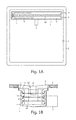
- Fig. 1A shows a schematic top view of a possible embodiment of a shower tray 1 provided with a recessed bottom 2 in which a drain channel 3 according to the invention is received.
- Drain channel 3 comprises a channel part 4 for used washing water provided with an outlet pipe 5 connected to the sewer, and a metal tube 6 provided with a feed 7 for cold mains water and a discharge 8 connected to a mixer tap (not shown) for a shower.
- Used washing water flows via an upper cover 9 provided with openings 10 along metal tube 6 and heats the mains water before it is carried to the mixer tap.
- Fig. 1B shows a schematic cross-section of this embodiment. Shown is channel part 4 with outlet pipe 5 in which is received the spirally curved metal tube 6 through which the mains water for heating flows in a position of use.
- the upper side of channel part 4 is widened all the way round so that upper cover 9 with openings 10 and a lower cover 11 can be placed recessed therein. The widened edge is further folded outward all the way round so that drain channel 3 can be glued into an opening in bottom 2 of shower tray 1 or can be cast into a floor.
- a collar 12 is arranged around openings 10.
- Lower cover 11 is provided with a channel-like recess 13 into which collar 12 fits.
- Lower cover 11 is further provided all the way round with openings 14 positioned precisely above spirally curved tube 6.
- spirally curved tube 6 When used washing water flows via openings 10 into channel part 4, the channel-like recess 13 is in the first instance filled and then forms together with collar 12 a stench trap. The water then rises until it can flow away via openings 14, wherein it drips in the form of separate droplets onto spirally curved tube 6.
- the parts of spirally curved tube 6 running in a longitudinal direction preferably run precisely horizontal in a position of use. The used washing water will then pass in droplet form through the successive windings, whereby a very good heat transfer is realized.
- spirally curved tube 6 is provided internally with a mechanically deformed metal wire 15 which increases the turbulence in the passing mains water.
- the heat exchanger is further operated in counterflow, which means in this case that the cold mains water is supplied to the lowest winding.
- a double-walled tube known in the field can be employed for tube 6 if this is required by local regulations, so that used washing water can never permeate into the mains water.
- Fig. 2A shows a top view of a drain channel 3 according to the invention in more detail. Shown are channel part 4, upper cover 9 with the slightly recessed openings 10, in addition to outlet pipe 5 and spirally curved tube 6. Openings 10 are preferably selected such that openings 14 in lower cover 11 in fact determine the throughflow, so that in a position of use there is always a layer of water on lower cover 11.
- Fig. 2B shows drain channel 3 without upper cover 9, so that lower cover 11 with holes 14 positioned precisely above spirally curved tube 6 can be seen.
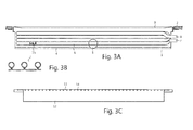
- Fig. 3A shows a longitudinal section of drain channel 3, wherein lower cover 11 is omitted for the sake of clarity. Visible are channel part 4 with upper cover 9 and spirally curved tube 6 with feed 7 for cold mains water and discharge 8.
- the half bends on the left-hand side are embodied such that the half bends and the parts of spirally curved tube 6 running in a longitudinal direction of channel part 4 run precisely horizontally, while the half bends on the right-hand side mutually connect these horizontal tube segments.
- the mechanically deformed metal wire 15 which is received in spirally curved tube 6 and provided here with loops. Other shapes are of course also possible, as long as they cause turbulence.
- the mechanically deformed wire can be placed in tube 6 before this latter is curved.
- Fig. 3B shows this mechanically deformed metal wire 15 in more detail.
- Fig. 3C shows a longitudinal section of lower cover 11, with channel-like recess 13 and holes 14.
- Channel part 4 upper cover 9 and lower cover 14 are preferably manufactured from stainless steel, while spirally curved tube 6 is preferably manufactured from copper. The whole can be cleaned periodically in simple manner by taking upper cover 9 and lower cover 14 out of channel part 4 and washing and/or brushing down the spirally shaped tube 6 then left clear.
- Fig. 4A shows an alternative embodiment of a heat exchanger 3 according to the invention, wherein heat exchanger 3 takes a circular form and can be built into for instance a tile floor 16 of a shared shower area in for instance a sports centre.
- Channel part 4 for used washing water is provided with an outlet pipe 5 connected to the sewer and spirally curved metal tube 6 is provided with a feed 7 for cold mains water and a discharge 8 connected to the mixer taps (not shown) for a number of showers.
- Used washing water flows via an upper cover 9 provided with openings 10 along metal tube 6 and heats the mains water before it is carried to the mixer taps.
- Fig. 4B shows a schematic cross-section of this embodiment. Shown is channel part 4 with outlet pipe 5, in which is received the spirally curved metal tube 6 through which the mains water for heating flows in a position of use.
- the upper part of the drain channel is widened all the way round so that upper cover 9 with openings 10 and a lower cover 11 can be placed recessed therein. The widened edge is further folded outward all the way round so that heat exchanger 3 can for instance be accommodated in a tile floor 16.
- a collar 12 is arranged around openings 10.
- Lower cover 11 is provided with a channel-like recess 13 into which collar 12 fits such that collar 12 and channel-like recess 13 together form a stench trap.
- Lower cover 11 is further provided all the way round with openings 14 positioned precisely above spirally curved tube 6 so that used washing water drips onto spirally shaped tube 6.
- tube 6 is provided internally with a plastic tube 17, whereby the flow speed of the water is increased, this providing for a more turbulent flow.
- Tube 17 further reduces the volume of spirally curved tube 6, this being important in combating legionella bacteria.
- the invention is of course not limited to the described and shown preferred embodiments. Both preferred embodiments relate for instance to a curved tube.
- the desired form of the heat exchanger can however also be obtained by connecting one or more tubes or tube parts running as precisely horizontal as possible to U-shaped coupling pieces at the ends thereof so as to form a tube.
- the tube is formed around an imaginary axis to form a spiral or coil.
- a number of tubes or tube parts running as precisely horizontal as possible can be positioned in rows lying one above another and be mutually connected to form a tube as described as component of the drain channel as according to claim 1.
- Use can for instance be made for this purpose of the serpentine-shaped tubes known from NL 1014215 which can be mutually connected in vertical or horizontal position. It is noted that the invention expressly also extends to all possible combinations of the described embodiments.
Applications Claiming Priority (1)
| Application Number | Priority Date | Filing Date | Title |
|---|---|---|---|
| NL1038387A NL1038387C2 (nl) | 2010-11-16 | 2010-11-16 | Afvoergoot voorzien van een warmtewisselaar en douchebak of douchecabine voorzien van een dergelijke afvoergoot. |
Publications (3)
| Publication Number | Publication Date |
|---|---|
| EP2453194A1 true EP2453194A1 (de) | 2012-05-16 |
| EP2453194B1 EP2453194B1 (de) | 2018-01-10 |
| EP2453194B8 EP2453194B8 (de) | 2022-03-02 |
Family
ID=45476304
Family Applications (1)
| Application Number | Title | Priority Date | Filing Date |
|---|---|---|---|
| EP11189335.0A Active EP2453194B8 (de) | 2010-11-16 | 2011-11-16 | Abwasserkanal ausgerüstet mit einem Wärmetauscher, und Duschwanne ausgerüstet mit solch einem Abwasserkanal |
Country Status (3)
| Country | Link |
|---|---|
| EP (1) | EP2453194B8 (de) |
| DK (1) | DK2453194T3 (de) |
| NL (1) | NL1038387C2 (de) |
Cited By (6)
| Publication number | Priority date | Publication date | Assignee | Title |
|---|---|---|---|---|
| WO2015106362A1 (de) | 2014-01-17 | 2015-07-23 | Joulia Ag | Wärmetauscher für eine dusche oder badewanne |
| EP3425288A1 (de) | 2017-07-07 | 2019-01-09 | Nederlandse Organisatie voor toegepast- natuurwetenschappelijk onderzoek TNO | Duschsystem und wärmetauschervorrichtung für eine dusche |
| US10888200B1 (en) | 2017-11-08 | 2021-01-12 | Sympateco, Inc. | Shower basin |
| USD913462S1 (en) | 2017-11-08 | 2021-03-16 | Sympateco, Inc. | Shower basin |
| USD913463S1 (en) | 2017-11-08 | 2021-03-16 | Sympateco, Inc. | Shower basin |
| US11220809B2 (en) | 2017-03-14 | 2022-01-11 | Nederlandse Organisatie Voor Toegepast-Natuurwetenschappelijk Onderzoek Tno | Shower system |
Citations (7)
| Publication number | Priority date | Publication date | Assignee | Title |
|---|---|---|---|---|
| US4542546A (en) * | 1983-06-30 | 1985-09-24 | Arthur Desgagnes | Heat recuperator adapted to a shower-cabin |
| WO2001012047A1 (en) * | 1999-08-17 | 2001-02-22 | Helast Bio Ab | Shower floor grating having flow preheating |
| NL1014215C1 (nl) | 2000-01-28 | 2001-07-31 | Gertjan Jelle De Wit | Doucheinrichting en douchebak. |
| NL1020068C1 (nl) | 2002-02-26 | 2003-08-27 | Gertjan Jelle De Wit | Warmtewisselaar voor het terugwinnen van warmte uit afvalwater. |
| FR2868796A1 (fr) * | 2004-04-09 | 2005-10-14 | Cao Fao Solutions | Installation sanitaire comp0rtant un dispositif de recuperation d'energie a echangeur thermique |
| NL1032458C1 (nl) * | 2006-09-07 | 2008-03-10 | Gertjan Jelle De Wit | Douchebak en warmtewisselaar. |
| US20100270009A1 (en) * | 2009-04-22 | 2010-10-28 | Gomyung-Enertech Co., Ltd. | Apparatus for recycling wasted heat using waste hot water |
-
2010
- 2010-11-16 NL NL1038387A patent/NL1038387C2/nl active
-
2011
- 2011-11-16 EP EP11189335.0A patent/EP2453194B8/de active Active
- 2011-11-16 DK DK11189335.0T patent/DK2453194T3/en active
Patent Citations (7)
| Publication number | Priority date | Publication date | Assignee | Title |
|---|---|---|---|---|
| US4542546A (en) * | 1983-06-30 | 1985-09-24 | Arthur Desgagnes | Heat recuperator adapted to a shower-cabin |
| WO2001012047A1 (en) * | 1999-08-17 | 2001-02-22 | Helast Bio Ab | Shower floor grating having flow preheating |
| NL1014215C1 (nl) | 2000-01-28 | 2001-07-31 | Gertjan Jelle De Wit | Doucheinrichting en douchebak. |
| NL1020068C1 (nl) | 2002-02-26 | 2003-08-27 | Gertjan Jelle De Wit | Warmtewisselaar voor het terugwinnen van warmte uit afvalwater. |
| FR2868796A1 (fr) * | 2004-04-09 | 2005-10-14 | Cao Fao Solutions | Installation sanitaire comp0rtant un dispositif de recuperation d'energie a echangeur thermique |
| NL1032458C1 (nl) * | 2006-09-07 | 2008-03-10 | Gertjan Jelle De Wit | Douchebak en warmtewisselaar. |
| US20100270009A1 (en) * | 2009-04-22 | 2010-10-28 | Gomyung-Enertech Co., Ltd. | Apparatus for recycling wasted heat using waste hot water |
Cited By (12)
| Publication number | Priority date | Publication date | Assignee | Title |
|---|---|---|---|---|
| WO2015106362A1 (de) | 2014-01-17 | 2015-07-23 | Joulia Ag | Wärmetauscher für eine dusche oder badewanne |
| US20160341490A1 (en) * | 2014-01-17 | 2016-11-24 | Joulia Ag | Heat exchanger for a shower or bathtub |
| CN106170674A (zh) * | 2014-01-17 | 2016-11-30 | 朱利亚股份公司 | 用于淋浴器或浴缸的换热器 |
| US10072897B2 (en) | 2014-01-17 | 2018-09-11 | Joulia Ag | Heat exchanger for a shower or bathtub |
| EP3372939A2 (de) | 2014-01-17 | 2018-09-12 | Joulia AG | Wärmetauscher für eine dusche oder badewanne |
| CN106170674B (zh) * | 2014-01-17 | 2019-01-04 | 朱利亚股份公司 | 用于淋浴器或浴缸的换热器 |
| RU2683058C2 (ru) * | 2014-01-17 | 2019-03-26 | Юлия Аг | Теплообменник для душа или ванны |
| US11220809B2 (en) | 2017-03-14 | 2022-01-11 | Nederlandse Organisatie Voor Toegepast-Natuurwetenschappelijk Onderzoek Tno | Shower system |
| EP3425288A1 (de) | 2017-07-07 | 2019-01-09 | Nederlandse Organisatie voor toegepast- natuurwetenschappelijk onderzoek TNO | Duschsystem und wärmetauschervorrichtung für eine dusche |
| US10888200B1 (en) | 2017-11-08 | 2021-01-12 | Sympateco, Inc. | Shower basin |
| USD913462S1 (en) | 2017-11-08 | 2021-03-16 | Sympateco, Inc. | Shower basin |
| USD913463S1 (en) | 2017-11-08 | 2021-03-16 | Sympateco, Inc. | Shower basin |
Also Published As
| Publication number | Publication date |
|---|---|
| EP2453194B1 (de) | 2018-01-10 |
| EP2453194B8 (de) | 2022-03-02 |
| DK2453194T3 (en) | 2018-03-05 |
| NL1038387C2 (nl) | 2012-05-21 |
Similar Documents
| Publication | Publication Date | Title |
|---|---|---|
| EP2453194B1 (de) | Abwasserkanal ausgerüstet mit einem Wärmetauscher, und Duschwanne ausgerüstet mit solch einem Abwasserkanal | |
| CN110260690B (zh) | 热交换器及套件、流体分配歧管、扰流器及能量回收系统 | |
| US10072897B2 (en) | Heat exchanger for a shower or bathtub | |
| EP3149253B1 (de) | Bodenablauf | |
| EP1809965B1 (de) | Vorrichtung und verfahren zur rückgewinnung von wärme aus abwasser | |
| EP2746710B1 (de) | Wärmetauscher sowie energierückgewinnungsvorrichtung und energierückgewinnungssystem mit dem wärmetauscher | |
| US6722421B2 (en) | Drainwater heat exchanger | |
| JP5571581B2 (ja) | 熱交換器 | |
| US8104532B2 (en) | Shower heat exchanger with clog-removable drain | |
| ATE546078T1 (de) | Durchlaufwärmetauscher zur zubereitung von getränken, insbesondere wasser-durchlauferhitzer für kaffeezubereitungsmaschinen | |
| US20140318737A1 (en) | Multi-phase distribution system, sub sea heat exchanger and a method of temperature control for hydrocarbons | |
| US20160003564A1 (en) | Method and device for transferring heat | |
| WO2012099476A1 (en) | A horizontal gyrating heat exchanger | |
| CA2775456C (en) | Shower heat exchanger with clog-removable drain | |
| EP2848874A1 (de) | Wassererwärmungsvorrichtung | |
| GB2482563A (en) | Hot water heater inlet baffle | |
| EP4113048A1 (de) | Vorrichtung zur wärmerückgewinnung aus grauwasser | |
| AU2004212549A1 (en) | Improved (shower drain) heat exchanger | |
| CZ37117U1 (cs) | Zařízení pro zpětné získávání tepla z odpadní vody stavebního objektu | |
| JP2009172536A (ja) | 中和器と中和器を備える燃焼装置 | |
| KR101533962B1 (ko) | 냉온수기 | |
| KR20140055286A (ko) | 냉수탱크 | |
| CZ309988B6 (cs) | Zařízení pro zpětné získávání tepla z odpadní vody stavebního objektu | |
| KR20090006763U (ko) | 폐수 열을 이용한 코일 방식의 열 교환장치 |
Legal Events
| Date | Code | Title | Description |
|---|---|---|---|
| PUAI | Public reference made under article 153(3) epc to a published international application that has entered the european phase |
Free format text: ORIGINAL CODE: 0009012 |
|
| AK | Designated contracting states |
Kind code of ref document: A1 Designated state(s): AL AT BE BG CH CY CZ DE DK EE ES FI FR GB GR HR HU IE IS IT LI LT LU LV MC MK MT NL NO PL PT RO RS SE SI SK SM TR |
|
| AX | Request for extension of the european patent |
Extension state: BA ME |
|
| 17P | Request for examination filed |
Effective date: 20121116 |
|
| GRAP | Despatch of communication of intention to grant a patent |
Free format text: ORIGINAL CODE: EPIDOSNIGR1 |
|
| STAA | Information on the status of an ep patent application or granted ep patent |
Free format text: STATUS: GRANT OF PATENT IS INTENDED |
|
| INTG | Intention to grant announced |
Effective date: 20170515 |
|
| GRAS | Grant fee paid |
Free format text: ORIGINAL CODE: EPIDOSNIGR3 |
|
| GRAJ | Information related to disapproval of communication of intention to grant by the applicant or resumption of examination proceedings by the epo deleted |
Free format text: ORIGINAL CODE: EPIDOSDIGR1 |
|
| GRAL | Information related to payment of fee for publishing/printing deleted |
Free format text: ORIGINAL CODE: EPIDOSDIGR3 |
|
| STAA | Information on the status of an ep patent application or granted ep patent |
Free format text: STATUS: REQUEST FOR EXAMINATION WAS MADE |
|
| GRAR | Information related to intention to grant a patent recorded |
Free format text: ORIGINAL CODE: EPIDOSNIGR71 |
|
| STAA | Information on the status of an ep patent application or granted ep patent |
Free format text: STATUS: GRANT OF PATENT IS INTENDED |
|
| INTC | Intention to grant announced (deleted) | ||
| INTG | Intention to grant announced |
Effective date: 20171004 |
|
| GRAA | (expected) grant |
Free format text: ORIGINAL CODE: 0009210 |
|
| STAA | Information on the status of an ep patent application or granted ep patent |
Free format text: STATUS: THE PATENT HAS BEEN GRANTED |
|
| AK | Designated contracting states |
Kind code of ref document: B1 Designated state(s): AL AT BE BG CH CY CZ DE DK EE ES FI FR GB GR HR HU IE IS IT LI LT LU LV MC MK MT NL NO PL PT RO RS SE SI SK SM TR |
|
| REG | Reference to a national code |
Ref country code: GB Ref legal event code: FG4D |
|
| REG | Reference to a national code |
Ref country code: CH Ref legal event code: EP Ref country code: AT Ref legal event code: REF Ref document number: 962857 Country of ref document: AT Kind code of ref document: T Effective date: 20180115 |
|
| REG | Reference to a national code |
Ref country code: IE Ref legal event code: FG4D |
|
| REG | Reference to a national code |
Ref country code: DE Ref legal event code: R096 Ref document number: 602011044880 Country of ref document: DE |
|
| REG | Reference to a national code |
Ref country code: DK Ref legal event code: T3 Effective date: 20180302 |
|
| REG | Reference to a national code |
Ref country code: CH Ref legal event code: NV Representative=s name: FABIANO, FRANKE AND MGT SAGL, CH |
|
| REG | Reference to a national code |
Ref country code: NL Ref legal event code: FP |
|
| REG | Reference to a national code |
Ref country code: AT Ref legal event code: MK05 Ref document number: 962857 Country of ref document: AT Kind code of ref document: T Effective date: 20180110 |
|
| PG25 | Lapsed in a contracting state [announced via postgrant information from national office to epo] |
Ref country code: ES Free format text: LAPSE BECAUSE OF FAILURE TO SUBMIT A TRANSLATION OF THE DESCRIPTION OR TO PAY THE FEE WITHIN THE PRESCRIBED TIME-LIMIT Effective date: 20180110 Ref country code: CY Free format text: LAPSE BECAUSE OF FAILURE TO SUBMIT A TRANSLATION OF THE DESCRIPTION OR TO PAY THE FEE WITHIN THE PRESCRIBED TIME-LIMIT Effective date: 20180110 Ref country code: LT Free format text: LAPSE BECAUSE OF FAILURE TO SUBMIT A TRANSLATION OF THE DESCRIPTION OR TO PAY THE FEE WITHIN THE PRESCRIBED TIME-LIMIT Effective date: 20180110 Ref country code: HR Free format text: LAPSE BECAUSE OF FAILURE TO SUBMIT A TRANSLATION OF THE DESCRIPTION OR TO PAY THE FEE WITHIN THE PRESCRIBED TIME-LIMIT Effective date: 20180110 Ref country code: NO Free format text: LAPSE BECAUSE OF FAILURE TO SUBMIT A TRANSLATION OF THE DESCRIPTION OR TO PAY THE FEE WITHIN THE PRESCRIBED TIME-LIMIT Effective date: 20180410 Ref country code: FI Free format text: LAPSE BECAUSE OF FAILURE TO SUBMIT A TRANSLATION OF THE DESCRIPTION OR TO PAY THE FEE WITHIN THE PRESCRIBED TIME-LIMIT Effective date: 20180110 |
|
| PG25 | Lapsed in a contracting state [announced via postgrant information from national office to epo] |
Ref country code: RS Free format text: LAPSE BECAUSE OF FAILURE TO SUBMIT A TRANSLATION OF THE DESCRIPTION OR TO PAY THE FEE WITHIN THE PRESCRIBED TIME-LIMIT Effective date: 20180110 Ref country code: AT Free format text: LAPSE BECAUSE OF FAILURE TO SUBMIT A TRANSLATION OF THE DESCRIPTION OR TO PAY THE FEE WITHIN THE PRESCRIBED TIME-LIMIT Effective date: 20180110 Ref country code: PL Free format text: LAPSE BECAUSE OF FAILURE TO SUBMIT A TRANSLATION OF THE DESCRIPTION OR TO PAY THE FEE WITHIN THE PRESCRIBED TIME-LIMIT Effective date: 20180110 Ref country code: BG Free format text: LAPSE BECAUSE OF FAILURE TO SUBMIT A TRANSLATION OF THE DESCRIPTION OR TO PAY THE FEE WITHIN THE PRESCRIBED TIME-LIMIT Effective date: 20180410 Ref country code: GR Free format text: LAPSE BECAUSE OF FAILURE TO SUBMIT A TRANSLATION OF THE DESCRIPTION OR TO PAY THE FEE WITHIN THE PRESCRIBED TIME-LIMIT Effective date: 20180411 Ref country code: SE Free format text: LAPSE BECAUSE OF FAILURE TO SUBMIT A TRANSLATION OF THE DESCRIPTION OR TO PAY THE FEE WITHIN THE PRESCRIBED TIME-LIMIT Effective date: 20180110 Ref country code: LV Free format text: LAPSE BECAUSE OF FAILURE TO SUBMIT A TRANSLATION OF THE DESCRIPTION OR TO PAY THE FEE WITHIN THE PRESCRIBED TIME-LIMIT Effective date: 20180110 Ref country code: IS Free format text: LAPSE BECAUSE OF FAILURE TO SUBMIT A TRANSLATION OF THE DESCRIPTION OR TO PAY THE FEE WITHIN THE PRESCRIBED TIME-LIMIT Effective date: 20180510 |
|
| REG | Reference to a national code |
Ref country code: DE Ref legal event code: R097 Ref document number: 602011044880 Country of ref document: DE |
|
| PG25 | Lapsed in a contracting state [announced via postgrant information from national office to epo] |
Ref country code: RO Free format text: LAPSE BECAUSE OF FAILURE TO SUBMIT A TRANSLATION OF THE DESCRIPTION OR TO PAY THE FEE WITHIN THE PRESCRIBED TIME-LIMIT Effective date: 20180110 Ref country code: AL Free format text: LAPSE BECAUSE OF FAILURE TO SUBMIT A TRANSLATION OF THE DESCRIPTION OR TO PAY THE FEE WITHIN THE PRESCRIBED TIME-LIMIT Effective date: 20180110 Ref country code: IT Free format text: LAPSE BECAUSE OF FAILURE TO SUBMIT A TRANSLATION OF THE DESCRIPTION OR TO PAY THE FEE WITHIN THE PRESCRIBED TIME-LIMIT Effective date: 20180110 Ref country code: EE Free format text: LAPSE BECAUSE OF FAILURE TO SUBMIT A TRANSLATION OF THE DESCRIPTION OR TO PAY THE FEE WITHIN THE PRESCRIBED TIME-LIMIT Effective date: 20180110 |
|
| PLBE | No opposition filed within time limit |
Free format text: ORIGINAL CODE: 0009261 |
|
| STAA | Information on the status of an ep patent application or granted ep patent |
Free format text: STATUS: NO OPPOSITION FILED WITHIN TIME LIMIT |
|
| PG25 | Lapsed in a contracting state [announced via postgrant information from national office to epo] |
Ref country code: SM Free format text: LAPSE BECAUSE OF FAILURE TO SUBMIT A TRANSLATION OF THE DESCRIPTION OR TO PAY THE FEE WITHIN THE PRESCRIBED TIME-LIMIT Effective date: 20180110 Ref country code: SK Free format text: LAPSE BECAUSE OF FAILURE TO SUBMIT A TRANSLATION OF THE DESCRIPTION OR TO PAY THE FEE WITHIN THE PRESCRIBED TIME-LIMIT Effective date: 20180110 Ref country code: CZ Free format text: LAPSE BECAUSE OF FAILURE TO SUBMIT A TRANSLATION OF THE DESCRIPTION OR TO PAY THE FEE WITHIN THE PRESCRIBED TIME-LIMIT Effective date: 20180110 |
|
| 26N | No opposition filed |
Effective date: 20181011 |
|
| PG25 | Lapsed in a contracting state [announced via postgrant information from national office to epo] |
Ref country code: SI Free format text: LAPSE BECAUSE OF FAILURE TO SUBMIT A TRANSLATION OF THE DESCRIPTION OR TO PAY THE FEE WITHIN THE PRESCRIBED TIME-LIMIT Effective date: 20180110 |
|
| REG | Reference to a national code |
Ref country code: CH Ref legal event code: PCAR Free format text: NEW ADDRESS: PIAZZETTA SAN CARLO 2, 6900 LUGANO (CH) |
|
| PG25 | Lapsed in a contracting state [announced via postgrant information from national office to epo] |
Ref country code: MC Free format text: LAPSE BECAUSE OF FAILURE TO SUBMIT A TRANSLATION OF THE DESCRIPTION OR TO PAY THE FEE WITHIN THE PRESCRIBED TIME-LIMIT Effective date: 20180110 |
|
| PG25 | Lapsed in a contracting state [announced via postgrant information from national office to epo] |
Ref country code: MT Free format text: LAPSE BECAUSE OF NON-PAYMENT OF DUE FEES Effective date: 20181116 |
|
| PG25 | Lapsed in a contracting state [announced via postgrant information from national office to epo] |
Ref country code: TR Free format text: LAPSE BECAUSE OF FAILURE TO SUBMIT A TRANSLATION OF THE DESCRIPTION OR TO PAY THE FEE WITHIN THE PRESCRIBED TIME-LIMIT Effective date: 20180110 |
|
| PG25 | Lapsed in a contracting state [announced via postgrant information from national office to epo] |
Ref country code: PT Free format text: LAPSE BECAUSE OF FAILURE TO SUBMIT A TRANSLATION OF THE DESCRIPTION OR TO PAY THE FEE WITHIN THE PRESCRIBED TIME-LIMIT Effective date: 20180110 |
|
| PG25 | Lapsed in a contracting state [announced via postgrant information from national office to epo] |
Ref country code: HU Free format text: LAPSE BECAUSE OF FAILURE TO SUBMIT A TRANSLATION OF THE DESCRIPTION OR TO PAY THE FEE WITHIN THE PRESCRIBED TIME-LIMIT; INVALID AB INITIO Effective date: 20111116 Ref country code: MK Free format text: LAPSE BECAUSE OF NON-PAYMENT OF DUE FEES Effective date: 20180110 |
|
| REG | Reference to a national code |
Ref country code: NL Ref legal event code: RE Free format text: SEIZURE, PRE-JUDGEMENT ATTACHEMENT Effective date: 20200902 |
|
| GRAT | Correction requested after decision to grant or after decision to maintain patent in amended form |
Free format text: ORIGINAL CODE: EPIDOSNCDEC |
|
| REG | Reference to a national code |
Ref country code: CH Ref legal event code: PK Free format text: BERICHTIGUNG B8 |
|
| REG | Reference to a national code |
Ref country code: LU Ref legal event code: PD Owner name: DUTCH SOLAR SYSTEMS B.V.; NL Free format text: FORMER OWNER: DE WIT, GERTJAN JELLE Effective date: 20220329 Ref country code: LU Ref legal event code: HC Owner name: DUTCH SOLAR SYSTEMS B.V.; NL Free format text: FORMER OWNER: DUTCH SOLAR SYSTEM B.V. Effective date: 20220329 |
|
| REG | Reference to a national code |
Ref country code: GB Ref legal event code: 732E Free format text: REGISTERED BETWEEN 20220331 AND 20220406 |
|
| REG | Reference to a national code |
Ref country code: NL Ref legal event code: PD Owner name: DUTCH SOLAR SYSTEMS B.V; NL Free format text: DETAILS ASSIGNMENT: CHANGE OF OWNER(S), ASSIGNMENT; FORMER OWNER NAME: DUTCH SOLAR SYSTEM B.V. Effective date: 20220330 |
|
| REG | Reference to a national code |
Ref country code: DE Ref legal event code: R081 Ref document number: 602011044880 Country of ref document: DE Owner name: ACO AHLMANN SE & CO. KG, DE Free format text: FORMER OWNERS: DE WIT, GERTJAN JELLE, RODEN, NL; DUTCH SOLAR SYSTEM B.V., ENSCHEDE, NL Ref country code: DE Ref legal event code: R081 Ref document number: 602011044880 Country of ref document: DE Owner name: DUTCH SOLAR SYSTEMS B.V., NL Free format text: FORMER OWNERS: DE WIT, GERTJAN JELLE, RODEN, NL; DUTCH SOLAR SYSTEM B.V., ENSCHEDE, NL |
|
| REG | Reference to a national code |
Ref country code: BE Ref legal event code: PD Owner name: DUTCH SOLAR SYSTEMS B.V.; NL Free format text: DETAILS ASSIGNMENT: CHANGE OF OWNER(S), ASSIGNMENT; FORMER OWNER NAME: DUTCH SOLAR SYSTEMS B.V. Effective date: 20220420 |
|
| PGFP | Annual fee paid to national office [announced via postgrant information from national office to epo] |
Ref country code: BE Payment date: 20220912 Year of fee payment: 12 |
|
| P01 | Opt-out of the competence of the unified patent court (upc) registered |
Effective date: 20230531 |
|
| REG | Reference to a national code |
Ref country code: NL Ref legal event code: PD Owner name: DUTCH SOLAR SYSTEMS B.V; NL Free format text: DETAILS ASSIGNMENT: CHANGE OF OWNER(S), ASSIGNMENT; FORMER OWNER NAME: DUTCH SOLAR SYSTEMS B.V Effective date: 20230901 |
|
| REG | Reference to a national code |
Ref country code: GB Ref legal event code: 732E Free format text: REGISTERED BETWEEN 20230901 AND 20230906 |
|
| REG | Reference to a national code |
Ref country code: DE Ref legal event code: R081 Ref document number: 602011044880 Country of ref document: DE Owner name: ACO AHLMANN SE & CO. KG, DE Free format text: FORMER OWNER: DUTCH SOLAR SYSTEMS B.V., GOOR, NL |
|
| REG | Reference to a national code |
Ref country code: BE Ref legal event code: PD Owner name: ACO AHLMANN SE & CO. KG; DE Free format text: DETAILS ASSIGNMENT: CHANGE OF OWNER(S), ASSIGNMENT; FORMER OWNER NAME: DUTCH SOLAR SYSTEMS B.V. Effective date: 20230904 |
|
| REG | Reference to a national code |
Ref country code: LU Ref legal event code: PD Owner name: ACO AHLMANN SE & CO. KG; DE Free format text: FORMER OWNER: DUTCH SOLAR SYSTEMS B.V. Effective date: 20230905 |
|
| REG | Reference to a national code |
Ref country code: DE Ref legal event code: R082 Ref document number: 602011044880 Country of ref document: DE Ref country code: DE Ref legal event code: R082 Ref document number: 602011044880 Country of ref document: DE Representative=s name: MEISSNER BOLTE PATENTANWAELTE RECHTSANWAELTE P, DE |
|
| REG | Reference to a national code |
Ref country code: DE Ref legal event code: R082 Ref document number: 602011044880 Country of ref document: DE Representative=s name: MEISSNER BOLTE PATENTANWAELTE RECHTSANWAELTE P, DE |
|
| PGFP | Annual fee paid to national office [announced via postgrant information from national office to epo] |
Ref country code: NL Payment date: 20231126 Year of fee payment: 13 Ref country code: LU Payment date: 20231127 Year of fee payment: 13 |
|
| PGFP | Annual fee paid to national office [announced via postgrant information from national office to epo] |
Ref country code: GB Payment date: 20231127 Year of fee payment: 13 |
|
| PGFP | Annual fee paid to national office [announced via postgrant information from national office to epo] |
Ref country code: IE Payment date: 20231127 Year of fee payment: 13 Ref country code: FR Payment date: 20231127 Year of fee payment: 13 Ref country code: DK Payment date: 20231127 Year of fee payment: 13 Ref country code: DE Payment date: 20231129 Year of fee payment: 13 Ref country code: CH Payment date: 20231201 Year of fee payment: 13 |
|
| PGFP | Annual fee paid to national office [announced via postgrant information from national office to epo] |
Ref country code: BE Payment date: 20231127 Year of fee payment: 13 |