EP2453169A2 - Recessed lighting device - Google Patents
Recessed lighting device Download PDFInfo
- Publication number
- EP2453169A2 EP2453169A2 EP11187359A EP11187359A EP2453169A2 EP 2453169 A2 EP2453169 A2 EP 2453169A2 EP 11187359 A EP11187359 A EP 11187359A EP 11187359 A EP11187359 A EP 11187359A EP 2453169 A2 EP2453169 A2 EP 2453169A2
- Authority
- EP
- European Patent Office
- Prior art keywords
- frame
- light fitting
- connection device
- device box
- light
- Prior art date
- Legal status (The legal status is an assumption and is not a legal conclusion. Google has not performed a legal analysis and makes no representation as to the accuracy of the status listed.)
- Withdrawn
Links
Images


Classifications
-
- F—MECHANICAL ENGINEERING; LIGHTING; HEATING; WEAPONS; BLASTING
- F21—LIGHTING
- F21V—FUNCTIONAL FEATURES OR DETAILS OF LIGHTING DEVICES OR SYSTEMS THEREOF; STRUCTURAL COMBINATIONS OF LIGHTING DEVICES WITH OTHER ARTICLES, NOT OTHERWISE PROVIDED FOR
- F21V21/00—Supporting, suspending, or attaching arrangements for lighting devices; Hand grips
- F21V21/02—Wall, ceiling, or floor bases; Fixing pendants or arms to the bases
- F21V21/04—Recessed bases
-
- F—MECHANICAL ENGINEERING; LIGHTING; HEATING; WEAPONS; BLASTING
- F21—LIGHTING
- F21V—FUNCTIONAL FEATURES OR DETAILS OF LIGHTING DEVICES OR SYSTEMS THEREOF; STRUCTURAL COMBINATIONS OF LIGHTING DEVICES WITH OTHER ARTICLES, NOT OTHERWISE PROVIDED FOR
- F21V17/00—Fastening of component parts of lighting devices, e.g. shades, globes, refractors, reflectors, filters, screens, grids or protective cages
- F21V17/02—Fastening of component parts of lighting devices, e.g. shades, globes, refractors, reflectors, filters, screens, grids or protective cages with provision for adjustment
-
- F—MECHANICAL ENGINEERING; LIGHTING; HEATING; WEAPONS; BLASTING
- F21—LIGHTING
- F21V—FUNCTIONAL FEATURES OR DETAILS OF LIGHTING DEVICES OR SYSTEMS THEREOF; STRUCTURAL COMBINATIONS OF LIGHTING DEVICES WITH OTHER ARTICLES, NOT OTHERWISE PROVIDED FOR
- F21V23/00—Arrangement of electric circuit elements in or on lighting devices
- F21V23/003—Arrangement of electric circuit elements in or on lighting devices the elements being electronics drivers or controllers for operating the light source, e.g. for a LED array
- F21V23/007—Arrangement of electric circuit elements in or on lighting devices the elements being electronics drivers or controllers for operating the light source, e.g. for a LED array enclosed in a casing
- F21V23/008—Arrangement of electric circuit elements in or on lighting devices the elements being electronics drivers or controllers for operating the light source, e.g. for a LED array enclosed in a casing the casing being outside the housing of the lighting device
-
- F—MECHANICAL ENGINEERING; LIGHTING; HEATING; WEAPONS; BLASTING
- F21—LIGHTING
- F21S—NON-PORTABLE LIGHTING DEVICES; SYSTEMS THEREOF; VEHICLE LIGHTING DEVICES SPECIALLY ADAPTED FOR VEHICLE EXTERIORS
- F21S8/00—Lighting devices intended for fixed installation
- F21S8/02—Lighting devices intended for fixed installation of recess-mounted type, e.g. downlighters
-
- F—MECHANICAL ENGINEERING; LIGHTING; HEATING; WEAPONS; BLASTING
- F21—LIGHTING
- F21V—FUNCTIONAL FEATURES OR DETAILS OF LIGHTING DEVICES OR SYSTEMS THEREOF; STRUCTURAL COMBINATIONS OF LIGHTING DEVICES WITH OTHER ARTICLES, NOT OTHERWISE PROVIDED FOR
- F21V23/00—Arrangement of electric circuit elements in or on lighting devices
- F21V23/04—Arrangement of electric circuit elements in or on lighting devices the elements being switches
- F21V23/0442—Arrangement of electric circuit elements in or on lighting devices the elements being switches activated by means of a sensor, e.g. motion or photodetectors
- F21V23/0471—Arrangement of electric circuit elements in or on lighting devices the elements being switches activated by means of a sensor, e.g. motion or photodetectors the sensor detecting the proximity, the presence or the movement of an object or a person
-
- F—MECHANICAL ENGINEERING; LIGHTING; HEATING; WEAPONS; BLASTING
- F21—LIGHTING
- F21V—FUNCTIONAL FEATURES OR DETAILS OF LIGHTING DEVICES OR SYSTEMS THEREOF; STRUCTURAL COMBINATIONS OF LIGHTING DEVICES WITH OTHER ARTICLES, NOT OTHERWISE PROVIDED FOR
- F21V29/00—Protecting lighting devices from thermal damage; Cooling or heating arrangements specially adapted for lighting devices or systems
- F21V29/50—Cooling arrangements
- F21V29/70—Cooling arrangements characterised by passive heat-dissipating elements, e.g. heat-sinks
- F21V29/74—Cooling arrangements characterised by passive heat-dissipating elements, e.g. heat-sinks with fins or blades
- F21V29/76—Cooling arrangements characterised by passive heat-dissipating elements, e.g. heat-sinks with fins or blades with essentially identical parallel planar fins or blades, e.g. with comb-like cross-section
- F21V29/763—Cooling arrangements characterised by passive heat-dissipating elements, e.g. heat-sinks with fins or blades with essentially identical parallel planar fins or blades, e.g. with comb-like cross-section the planes containing the fins or blades having the direction of the light emitting axis
-
- F—MECHANICAL ENGINEERING; LIGHTING; HEATING; WEAPONS; BLASTING
- F21—LIGHTING
- F21Y—INDEXING SCHEME ASSOCIATED WITH SUBCLASSES F21K, F21L, F21S and F21V, RELATING TO THE FORM OR THE KIND OF THE LIGHT SOURCES OR OF THE COLOUR OF THE LIGHT EMITTED
- F21Y2115/00—Light-generating elements of semiconductor light sources
- F21Y2115/10—Light-emitting diodes [LED]
Definitions
- This invention relates to a light fitting, and in particular to a recessed light fitting.
- the dimensions of the light fitting to be recessed are to be suitable for the installation place in question.
- a drawback with the above solution is that a plurality of variations need to be manufactured of the same light fitting.
- the object of the present invention is to solve the above-described problem and to provide a light fitting which may be installed in a simple and flexible manner in places whose measurements differ from one another. This is achieved with a light fitting in accordance with the attached independent claim 1.
- connection device box When a connection device box is arranged in connection with the frame of the light fitting, some of the parts belonging to the light fitting may be arranged apart from the actual light fitting frame, whereby the shaping of the light fitting frame becomes more flexible such that it will be utilizable in a variety of installations. Moreover, when the light fitting frame and the connection device box are manufactured such that in connection with installation they may be arranged in alternative positions in relation to one another, it is possible to provide a light fitting that is adaptable to use more flexibly than before. Thus, depending on the installation place, the mutual position of the connection device box and the frame may be arranged such that the light fitting is suitable for installation in that particular installation place.
- Figures 1 and 2 show a first embodiment of a light fitting 1 seen obliquely from above and obliquely from below.
- the light fitting 1 comprises a frame 2, which may be made of a suitable plastic or metal material and which is embedded at least partly in a surrounding structure in connection with installation.
- the frame 2 of the light fitting 1 may accommodate one or more light sources 10.
- the question may be of high-power light emitting diodes, i.e. so-called high-power leds, whose power may be 1 to 3 W/piece, for instance.
- the light sources 10 are arranged in the light fitting frame 2 such that the light produced thereby is able to propagate to the space under the light fitting through an open lower part of the frame 2.
- the example of Figures 1 and 2 employs fasteners 4 arranged on the outer surface of the frame 1.
- the distance which these fasteners 4 project from the frame 2 is adjustable, so that the light fitting 1 can be secured into place in the surrounding structure by means of the fasteners which are pressed against the surrounding structure.
- the fasteners may be, for instance, metal wire loops or plastic pins, which press outwardly from the frame due to an intermediary piece 5, which intermediary piece 5 moves along a screw 6, when the screw head is turned from inside the light fitting frame 2 with a screw driver, for instance.
- a connection device box 7 is secured to the frame 2 through a securing member 8.
- the securing member 8 may be, for instance, a screw or a rivet, through which the connection device box 7 is pivoted to the frame 2 such that their mutual positions may be changed by pivoting the connection device box about the securing member 8.
- a plurality of securing members 8 may be employed, for instance, a plurality of screws and holes provided for them, whereby the connection device box 7 is securable to the frame 2 by means of these securing members in any one of the plurality of alternative positions in relation to the frame.
- the frame 2 and the connection device box 7 are provided with bulges and recesses which enable the securing of the connection device box 7 to the frame 2 by using so-called click-into-place connection, in which the reliefs are pressed in the recesses.
- the connection device box may be secured in a desired position in relation to the frame.
- FIGs 3 to 5 illustrate the installation of the light fitting 1 of Figures 1 and 2 in various locations.
- the light fitting 1 is shown embedded in a ceiling 15.
- the light fitting frame 2 penetrates partly inside the structure of the ceiling 15 until a collar in its lower part will be against the lower surface of the ceiling 15.
- connection device box 7 is arranged in such a position in relation to the frame 2 that it projects to the left from the frame 2, in parallel with the ceiling 15. In that case the recess installation depth D1 of the light fitting 1 is at its smallest. In this position the light fitting 1 is utilizable, for instance, for a ceiling structure, where the thickness D2 of the ceiling is relatively small. Thanks to the location of the connection device box 7 a conductor connected to the power supply network may be readily coupled in a space above the ceiling 15 to a connector 9 locating in the connection device box. Thus, it is possible to arrange power supply through the connection device box to the light source 10 or light sources, which are also coupled to the connector 9. In practice, the connector 9 may be designed to receive individual electric conductors. Alternatively, it may be a connector that receives a plug.
- connection device box 7 between the connector 9 and the light source, when necessary.
- connection device box 7 is pivoted about the pivot point provided by the securing member 8 to the right in relation to the frame 2.
- the securing member 8 constituting the pivot point is arranged eccentrically to the connection device box 7, i.e. offset from the centre line 12 of its side part. Consequently, the recess installation depth D1 of the light fitting 1 is larger in the case of Figure 4 in comparison to Figure 3 .
- the thickness D2 of the ceiling may also be larger in the case of Figure 4 in comparison to Figure 3 . Consequently, thanks to the eccentricity, it is possible to provide three different depths for recess installation, depending on the position ( Figure 3, Figure 4 or Figure 5 ) to which the connection device box is pivoted.
- connection device box 7 is pivoted about the pivot point provided by the securing element 8 almost to an upright position in relation to the frame 2, to be above said frame.
- the recess installation depth D1 of the light fitting 1 is at its largest.
- the thickness D2 of the ceiling may be considerably larger than in the cases of Figures 3 and 4 .
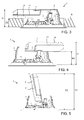
- Figures 6 to 7 illustrate the installation of the light fitting 1 of Figures 1 and 2 in a fixture housing 14.
- the fixture housing 14 consists of a hollow, cylindrical part inside which the light fitting is recessed.
- the connection device box 7 may be arranged in the upright position, as shown in Figures 6 and 7 , or alternatively, it may be turned to a horizontal position, as shown in Figures 3 and 4 .
- FIG 6 where the light fitting 1 is shown partly cut open, shows in addition to the light sources 10 a movement sensor 13, which is not necessary in all implementations.
- the movement sensor 13 may control supply of electricity to the light sources 10 such that they are only supplied when the movement sensor 13 has detected a person moving in a dark space beneath the light fitting, for instance.
- the movement sensor 13 may be a PIR (Passive Infrared) movement sensor, for instance, which allows detection of a person in the space on the basis of thermal radiation, a movement sensor based on radar technology, which includes a microwave transmitter and a microwave receiver, or an ultrasound receiver, which allows detection of motion in a space.
- PIR Passive Infrared
Abstract
Description
- This invention relates to a light fitting, and in particular to a recessed light fitting.
- To enable recessed installation for a light fitting in as simple and flexible manner as possible, the dimensions of the light fitting to be recessed are to be suitable for the installation place in question.
- For instance, in connection with ceilings, there are typically variations in the thickness of the actual ceiling and also in dimensions of a space above the ceiling. In order to take these variations into account, there is previously known a solution, in which several variations having different dimensions have been manufactured of the same light fitting. Thus, there is a specific, individual light fitting for different ceiling thicknesses and recess installation depths, the light fitting being designed to fit the particular installation place in question.
- A drawback with the above solution is that a plurality of variations need to be manufactured of the same light fitting.
- The object of the present invention is to solve the above-described problem and to provide a light fitting which may be installed in a simple and flexible manner in places whose measurements differ from one another. This is achieved with a light fitting in accordance with the attached
independent claim 1. - When a connection device box is arranged in connection with the frame of the light fitting, some of the parts belonging to the light fitting may be arranged apart from the actual light fitting frame, whereby the shaping of the light fitting frame becomes more flexible such that it will be utilizable in a variety of installations. Moreover, when the light fitting frame and the connection device box are manufactured such that in connection with installation they may be arranged in alternative positions in relation to one another, it is possible to provide a light fitting that is adaptable to use more flexibly than before. Thus, depending on the installation place, the mutual position of the connection device box and the frame may be arranged such that the light fitting is suitable for installation in that particular installation place.
- Preferred embodiments of the light fitting in accordance with the invention are disclosed in the attached dependent claims.
- The invention will be described in the following in greater detail by way of example and with reference to the accompanying figures, in which:
-
Figure 1 shows a first embodiment of a light fitting seen obliquely from above; -
Figure 2 shows the first embodiment of the light fitting seen obliquely from below; -
Figures 3 to 5 illustrate the installation of the light fitting ofFigures 1 and 2 in various locations; and -
Figures 6 to 7 illustrate the installation of the light fitting ofFigures 1 and 2 in a fixture housing. -
Figures 1 and 2 show a first embodiment of alight fitting 1 seen obliquely from above and obliquely from below. Thelight fitting 1 comprises aframe 2, which may be made of a suitable plastic or metal material and which is embedded at least partly in a surrounding structure in connection with installation. - The
frame 2 of thelight fitting 1 may accommodate one or morelight sources 10. For instance, the question may be of high-power light emitting diodes, i.e. so-called high-power leds, whose power may be 1 to 3 W/piece, for instance. Thelight sources 10 are arranged in thelight fitting frame 2 such that the light produced thereby is able to propagate to the space under the light fitting through an open lower part of theframe 2. - In order to secure the recessed light fitting 1 to the structure that at least partly surrounds the
frame 2, such as the ceiling, the example ofFigures 1 and 2 employsfasteners 4 arranged on the outer surface of theframe 1. The distance which thesefasteners 4 project from theframe 2 is adjustable, so that thelight fitting 1 can be secured into place in the surrounding structure by means of the fasteners which are pressed against the surrounding structure. The fasteners may be, for instance, metal wire loops or plastic pins, which press outwardly from the frame due to anintermediary piece 5, whichintermediary piece 5 moves along ascrew 6, when the screw head is turned from inside thelight fitting frame 2 with a screw driver, for instance. - In the case of
Figures 1 and 2 , aconnection device box 7 is secured to theframe 2 through a securingmember 8. The securingmember 8 may be, for instance, a screw or a rivet, through which theconnection device box 7 is pivoted to theframe 2 such that their mutual positions may be changed by pivoting the connection device box about the securingmember 8. Alternatively, a plurality of securingmembers 8 may be employed, for instance, a plurality of screws and holes provided for them, whereby theconnection device box 7 is securable to theframe 2 by means of these securing members in any one of the plurality of alternative positions in relation to the frame. Further, it is conceivable that theframe 2 and theconnection device box 7 are provided with bulges and recesses which enable the securing of theconnection device box 7 to theframe 2 by using so-called click-into-place connection, in which the reliefs are pressed in the recesses. In this case there are also several alternative, cooperating bulges and recesses so that the connection device box may be secured in a desired position in relation to the frame. -
Figures 3 to 5 illustrate the installation of thelight fitting 1 ofFigures 1 and 2 in various locations. - In the example of
Figure 3 , thelight fitting 1 is shown embedded in aceiling 15. In that case thelight fitting frame 2 penetrates partly inside the structure of theceiling 15 until a collar in its lower part will be against the lower surface of theceiling 15. - In the case of
Figure 3 , theconnection device box 7 is arranged in such a position in relation to theframe 2 that it projects to the left from theframe 2, in parallel with theceiling 15. In that case the recess installation depth D1 of thelight fitting 1 is at its smallest. In this position thelight fitting 1 is utilizable, for instance, for a ceiling structure, where the thickness D2 of the ceiling is relatively small. Thanks to the location of the connection device box 7 a conductor connected to the power supply network may be readily coupled in a space above theceiling 15 to aconnector 9 locating in the connection device box. Thus, it is possible to arrange power supply through the connection device box to thelight source 10 or light sources, which are also coupled to theconnector 9. In practice, theconnector 9 may be designed to receive individual electric conductors. Alternatively, it may be a connector that receives a plug. - Depending on the type of the
light source 10, it is also possible to arrange apower source 11 or an inverter in theconnection device box 7 between theconnector 9 and the light source, when necessary. - The example of
Figure 4 corresponds to that ofFigure 3 in all other respects but in the case ofFigure 4 theconnection device box 7 is pivoted about the pivot point provided by the securingmember 8 to the right in relation to theframe 2. It appears fromFigure 2 that thesecuring member 8 constituting the pivot point is arranged eccentrically to theconnection device box 7, i.e. offset from thecentre line 12 of its side part. Consequently, the recess installation depth D1 of thelight fitting 1 is larger in the case ofFigure 4 in comparison toFigure 3 . The thickness D2 of the ceiling may also be larger in the case ofFigure 4 in comparison toFigure 3 . Consequently, thanks to the eccentricity, it is possible to provide three different depths for recess installation, depending on the position (Figure 3, Figure 4 or Figure 5 ) to which the connection device box is pivoted. - The example of
Figure 5 corresponds to that ofFigures 4 and 5 in all other respects but in the case ofFigure 5 theconnection device box 7 is pivoted about the pivot point provided by thesecuring element 8 almost to an upright position in relation to theframe 2, to be above said frame. When the connection device box is in a completely upright position, the recess installation depth D1 of thelight fitting 1 is at its largest. In that case also the thickness D2 of the ceiling may be considerably larger than in the cases ofFigures 3 and 4 . - It appears from
Figures 3 to 5 that thanks to changes in mutual positions of the connectingframe box 7 and theframe 2, performed in connection with installation, the one and the sameindividual light fitting 1 is applicable to a variety of mounting sites. In order to achieve this, use of a securing member to serve as a pivot point is not absolutely necessary, but instead of the pivoting there may be employed a securing member or members, implemented in another manner, which enable securing of the connection device box to the frame in any one of the several alternative positions. -
Figures 6 to 7 illustrate the installation of thelight fitting 1 ofFigures 1 and 2 in afixture housing 14. - In the example shown in
Figures 6 and 7 thefixture housing 14 consists of a hollow, cylindrical part inside which the light fitting is recessed. Depending on the dimensions of thefixture housing 14, theconnection device box 7 may be arranged in the upright position, as shown inFigures 6 and 7 , or alternatively, it may be turned to a horizontal position, as shown inFigures 3 and 4 . -
Figure 6 , where thelight fitting 1 is shown partly cut open, shows in addition to the light sources 10 amovement sensor 13, which is not necessary in all implementations. When themovement sensor 13 is employed, it may control supply of electricity to thelight sources 10 such that they are only supplied when themovement sensor 13 has detected a person moving in a dark space beneath the light fitting, for instance. Themovement sensor 13 may be a PIR (Passive Infrared) movement sensor, for instance, which allows detection of a person in the space on the basis of thermal radiation, a movement sensor based on radar technology, which includes a microwave transmitter and a microwave receiver, or an ultrasound receiver, which allows detection of motion in a space. - It is to be understood that the above description and the relating figures are only intended to illustrate the present invention. It will be obvious to a person skilled in the art that the invention may also be varied and modified in other ways without departing from the scope of the invention.
Claims (5)
- A recessed light fitting (1) comprising a frame (2) to receive one or more light sources (10), characterized in
that the light fitting (1) comprises, in addition to the frame (2), a connection device box (7), through which power supply is arranged for the one or more light sources (10) in the frame (2),
that the light fitting (1) includes a securing member (8), by which the connection device box (7) is eccentrically pivoted to the frame (2) such that the securing member (8) is offset from a centre line (12) of a side part of the connection device box, and
that to adapt the shape of the light fitting (1) to meet the requirements of the installation location, the connection device box (7) is pivotable by means of the securing member (8) in relation to the frame (2) so as to change the mutual position of the connection device box (7) and the frame (2). - The light fitting of claim 1, characterized in that on the outer surface of the frame (2) of the light fitting (1) there are arranged fasteners (4) whose lateral projection from the frame (2) is adjustable so as to secure the recessed frame (2) to a structure (15) surrounding the frame.
- The light fitting of any one of claims 1 to 2, characterized in that in the connection device box (7) there is arranged a connector (9), coupled to at least said one or more light sources (10), to receive a conductor connected to a power supply network.
- The light fitting of any one of claims 1 to 3, characterized in that a power source (11) or an inverter is arranged in the connection device box (7) for providing electric supply to said one or more light sources (10).
- The light fitting of any one of claims 1 to 4, characterized in that said one or more light sources (10) is a high-power light emitting diode.
Applications Claiming Priority (1)
| Application Number | Priority Date | Filing Date | Title |
|---|---|---|---|
| FI20106200A FI20106200A (en) | 2010-11-15 | 2010-11-15 | Lamp |
Publications (2)
| Publication Number | Publication Date |
|---|---|
| EP2453169A2 true EP2453169A2 (en) | 2012-05-16 |
| EP2453169A3 EP2453169A3 (en) | 2013-01-09 |
Family
ID=43268980
Family Applications (1)
| Application Number | Title | Priority Date | Filing Date |
|---|---|---|---|
| EP11187359A Withdrawn EP2453169A3 (en) | 2010-11-15 | 2011-11-01 | Recessed lighting device |
Country Status (2)
| Country | Link |
|---|---|
| EP (1) | EP2453169A3 (en) |
| FI (1) | FI20106200A (en) |
Cited By (31)
| Publication number | Priority date | Publication date | Assignee | Title |
|---|---|---|---|---|
| CN104272019A (en) * | 2012-07-04 | 2015-01-07 | 普司科Led股份有限公司 | Optical semiconductor lighting device |
| US9039254B2 (en) | 2013-03-08 | 2015-05-26 | Michael D. Danesh | Wide angle adjustable retrofit lamp for recessed lighting |
| GB2524095A (en) * | 2014-03-14 | 2015-09-16 | Ac Dc Led Ltd | Luminaires |
| US9964266B2 (en) | 2013-07-05 | 2018-05-08 | DMF, Inc. | Unified driver and light source assembly for recessed lighting |
| USD833977S1 (en) | 2015-10-05 | 2018-11-20 | DMF, Inc. | Electrical junction box |
| US10139059B2 (en) | 2014-02-18 | 2018-11-27 | DMF, Inc. | Adjustable compact recessed lighting assembly with hangar bars |
| USD847414S1 (en) | 2015-05-29 | 2019-04-30 | DMF, Inc. | Lighting module |
| USD864877S1 (en) | 2019-01-29 | 2019-10-29 | DMF, Inc. | Plastic deep electrical junction box with a lighting module mounting yoke |
| US10488000B2 (en) | 2017-06-22 | 2019-11-26 | DMF, Inc. | Thin profile surface mount lighting apparatus |
| US10551044B2 (en) | 2015-11-16 | 2020-02-04 | DMF, Inc. | Recessed lighting assembly |
| US10563850B2 (en) | 2015-04-22 | 2020-02-18 | DMF, Inc. | Outer casing for a recessed lighting fixture |
| US10663153B2 (en) | 2017-12-27 | 2020-05-26 | DMF, Inc. | Methods and apparatus for adjusting a luminaire |
| US10753558B2 (en) | 2013-07-05 | 2020-08-25 | DMF, Inc. | Lighting apparatus and methods |
| USD901398S1 (en) | 2019-01-29 | 2020-11-10 | DMF, Inc. | Plastic deep electrical junction box |
| USD902871S1 (en) | 2018-06-12 | 2020-11-24 | DMF, Inc. | Plastic deep electrical junction box |
| USD905327S1 (en) | 2018-05-17 | 2020-12-15 | DMF, Inc. | Light fixture |
| US10975570B2 (en) | 2017-11-28 | 2021-04-13 | DMF, Inc. | Adjustable hanger bar assembly |
| US11060705B1 (en) | 2013-07-05 | 2021-07-13 | DMF, Inc. | Compact lighting apparatus with AC to DC converter and integrated electrical connector |
| US11067231B2 (en) | 2017-08-28 | 2021-07-20 | DMF, Inc. | Alternate junction box and arrangement for lighting apparatus |
| US11231154B2 (en) | 2018-10-02 | 2022-01-25 | Ver Lighting Llc | Bar hanger assembly with mating telescoping bars |
| US11255497B2 (en) | 2013-07-05 | 2022-02-22 | DMF, Inc. | Adjustable electrical apparatus with hangar bars for installation in a building |
| USD945054S1 (en) | 2017-06-22 | 2022-03-01 | DMF, Inc. | Light fixture |
| US11274821B2 (en) | 2019-09-12 | 2022-03-15 | DMF, Inc. | Lighting module with keyed heat sink coupled to thermally conductive trim |
| US11306903B2 (en) | 2020-07-17 | 2022-04-19 | DMF, Inc. | Polymer housing for a lighting system and methods for using same |
| US11391442B2 (en) | 2018-06-11 | 2022-07-19 | DMF, Inc. | Polymer housing for a recessed lighting system and methods for using same |
| US11435064B1 (en) | 2013-07-05 | 2022-09-06 | DMF, Inc. | Integrated lighting module |
| USD966877S1 (en) | 2019-03-14 | 2022-10-18 | Ver Lighting Llc | Hanger bar for a hanger bar assembly |
| USD970081S1 (en) | 2018-05-24 | 2022-11-15 | DMF, Inc. | Light fixture |
| US11585517B2 (en) | 2020-07-23 | 2023-02-21 | DMF, Inc. | Lighting module having field-replaceable optics, improved cooling, and tool-less mounting features |
| USD990030S1 (en) | 2020-07-17 | 2023-06-20 | DMF, Inc. | Housing for a lighting system |
| USD1012864S1 (en) | 2019-01-29 | 2024-01-30 | DMF, Inc. | Portion of a plastic deep electrical junction box |
Family Cites Families (7)
| Publication number | Priority date | Publication date | Assignee | Title |
|---|---|---|---|---|
| JP2571791B2 (en) * | 1987-08-13 | 1997-01-16 | 松下電工株式会社 | Emergency lighting equipment with built-in battery |
| DE29815368U1 (en) * | 1998-08-27 | 1998-11-19 | Koch Wilhelm Gmbh | Low-voltage recessed ceiling light |
| DE10047407A1 (en) * | 2000-09-26 | 2002-01-03 | Wila Leuchten Ag Sevelen | Built-in lighting unit e.g. for suspended ceilings, has an equipment box hinged on lamp-holder |
| JP4755074B2 (en) * | 2006-11-30 | 2011-08-24 | 三菱電機株式会社 | Recessed lighting fixture |
| GB0720402D0 (en) * | 2007-10-18 | 2007-11-28 | Nvc Mfg Ltd | Eletrical fittings |
| US20100294560A1 (en) * | 2007-12-21 | 2010-11-25 | Torben Dahl | Mounting device for mounting electric components |
| EP2180241B1 (en) * | 2008-10-22 | 2012-08-29 | Toshiba Lighting & Technology Corporation | Lighting Apparatus |
-
2010
- 2010-11-15 FI FI20106200A patent/FI20106200A/en not_active Application Discontinuation
-
2011
- 2011-11-01 EP EP11187359A patent/EP2453169A3/en not_active Withdrawn
Non-Patent Citations (1)
| Title |
|---|
| None |
Cited By (63)
| Publication number | Priority date | Publication date | Assignee | Title |
|---|---|---|---|---|
| EP2871410A4 (en) * | 2012-07-04 | 2016-01-20 | Posco Led Co Ltd | Optical semiconductor lighting device |
| CN104272019A (en) * | 2012-07-04 | 2015-01-07 | 普司科Led股份有限公司 | Optical semiconductor lighting device |
| US9039254B2 (en) | 2013-03-08 | 2015-05-26 | Michael D. Danesh | Wide angle adjustable retrofit lamp for recessed lighting |
| US10753558B2 (en) | 2013-07-05 | 2020-08-25 | DMF, Inc. | Lighting apparatus and methods |
| US10408395B2 (en) | 2013-07-05 | 2019-09-10 | DMF, Inc. | Recessed lighting systems |
| US11255497B2 (en) | 2013-07-05 | 2022-02-22 | DMF, Inc. | Adjustable electrical apparatus with hangar bars for installation in a building |
| US9964266B2 (en) | 2013-07-05 | 2018-05-08 | DMF, Inc. | Unified driver and light source assembly for recessed lighting |
| US11060705B1 (en) | 2013-07-05 | 2021-07-13 | DMF, Inc. | Compact lighting apparatus with AC to DC converter and integrated electrical connector |
| US11808430B2 (en) | 2013-07-05 | 2023-11-07 | DMF, Inc. | Adjustable electrical apparatus with hangar bars for installation in a building |
| US10816148B2 (en) | 2013-07-05 | 2020-10-27 | DMF, Inc. | Recessed lighting systems |
| US10982829B2 (en) | 2013-07-05 | 2021-04-20 | DMF, Inc. | Adjustable electrical apparatus with hangar bars for installation in a building |
| US11085597B2 (en) | 2013-07-05 | 2021-08-10 | DMF, Inc. | Recessed lighting systems |
| US11435064B1 (en) | 2013-07-05 | 2022-09-06 | DMF, Inc. | Integrated lighting module |
| USD847415S1 (en) | 2014-02-18 | 2019-04-30 | DMF, Inc. | Unified casting light module |
| US10139059B2 (en) | 2014-02-18 | 2018-11-27 | DMF, Inc. | Adjustable compact recessed lighting assembly with hangar bars |
| USD907284S1 (en) | 2014-02-18 | 2021-01-05 | DMF, Inc. | Module applied to a lighting assembly |
| US11028982B2 (en) | 2014-02-18 | 2021-06-08 | DMF, Inc. | Adjustable lighting assembly with hangar bars |
| USD924467S1 (en) | 2014-02-18 | 2021-07-06 | DMF, Inc. | Unified casting light module |
| USD939134S1 (en) | 2014-02-18 | 2021-12-21 | DMF, Inc. | Module applied to a lighting assembly |
| GB2524095A (en) * | 2014-03-14 | 2015-09-16 | Ac Dc Led Ltd | Luminaires |
| WO2015136313A1 (en) * | 2014-03-14 | 2015-09-17 | Ac/Dc Led Limited | Luminaires |
| US10215395B2 (en) | 2014-03-14 | 2019-02-26 | Ac/Dc Led Limited | Luminaires |
| EP3117145B1 (en) * | 2014-03-14 | 2018-10-24 | AC/DC Led Limited | Luminaires |
| CN106104154A (en) * | 2014-03-14 | 2016-11-09 | Ac/Dc Led 有限公司 | Luminaire |
| CN106104154B (en) * | 2014-03-14 | 2019-09-27 | Ac/Dc Led 有限公司 | Luminaire |
| US10563850B2 (en) | 2015-04-22 | 2020-02-18 | DMF, Inc. | Outer casing for a recessed lighting fixture |
| US11118768B2 (en) | 2015-04-22 | 2021-09-14 | DMF, Inc. | Outer casing for a recessed lighting fixture |
| US11435066B2 (en) | 2015-04-22 | 2022-09-06 | DMF, Inc. | Outer casing for a recessed lighting fixture |
| US10591120B2 (en) | 2015-05-29 | 2020-03-17 | DMF, Inc. | Lighting module for recessed lighting systems |
| USD847414S1 (en) | 2015-05-29 | 2019-04-30 | DMF, Inc. | Lighting module |
| USD925109S1 (en) | 2015-05-29 | 2021-07-13 | DMF, Inc. | Lighting module |
| US11022259B2 (en) | 2015-05-29 | 2021-06-01 | DMF, Inc. | Lighting module with separated light source and power supply circuit board |
| USD944212S1 (en) | 2015-10-05 | 2022-02-22 | DMF, Inc. | Electrical junction box |
| USD833977S1 (en) | 2015-10-05 | 2018-11-20 | DMF, Inc. | Electrical junction box |
| USD848375S1 (en) | 2015-10-05 | 2019-05-14 | DMF, Inc. | Electrical junction box |
| USD851046S1 (en) | 2015-10-05 | 2019-06-11 | DMF, Inc. | Electrical Junction Box |
| US10551044B2 (en) | 2015-11-16 | 2020-02-04 | DMF, Inc. | Recessed lighting assembly |
| US11668455B2 (en) | 2015-11-16 | 2023-06-06 | DMF, Inc. | Casing for lighting assembly |
| US11242983B2 (en) | 2015-11-16 | 2022-02-08 | DMF, Inc. | Casing for lighting assembly |
| USD945054S1 (en) | 2017-06-22 | 2022-03-01 | DMF, Inc. | Light fixture |
| US11293609B2 (en) | 2017-06-22 | 2022-04-05 | DMF, Inc. | Thin profile surface mount lighting apparatus |
| US10663127B2 (en) | 2017-06-22 | 2020-05-26 | DMF, Inc. | Thin profile surface mount lighting apparatus |
| US11047538B2 (en) | 2017-06-22 | 2021-06-29 | DMF, Inc. | LED lighting apparatus with adapter bracket for a junction box |
| US10488000B2 (en) | 2017-06-22 | 2019-11-26 | DMF, Inc. | Thin profile surface mount lighting apparatus |
| US11649938B2 (en) | 2017-06-22 | 2023-05-16 | DMF, Inc. | Thin profile surface mount lighting apparatus |
| US11067231B2 (en) | 2017-08-28 | 2021-07-20 | DMF, Inc. | Alternate junction box and arrangement for lighting apparatus |
| US10975570B2 (en) | 2017-11-28 | 2021-04-13 | DMF, Inc. | Adjustable hanger bar assembly |
| US10663153B2 (en) | 2017-12-27 | 2020-05-26 | DMF, Inc. | Methods and apparatus for adjusting a luminaire |
| US11448384B2 (en) | 2017-12-27 | 2022-09-20 | DMF, Inc. | Methods and apparatus for adjusting a luminaire |
| USD905327S1 (en) | 2018-05-17 | 2020-12-15 | DMF, Inc. | Light fixture |
| USD970081S1 (en) | 2018-05-24 | 2022-11-15 | DMF, Inc. | Light fixture |
| US11391442B2 (en) | 2018-06-11 | 2022-07-19 | DMF, Inc. | Polymer housing for a recessed lighting system and methods for using same |
| USD902871S1 (en) | 2018-06-12 | 2020-11-24 | DMF, Inc. | Plastic deep electrical junction box |
| USD903605S1 (en) | 2018-06-12 | 2020-12-01 | DMF, Inc. | Plastic deep electrical junction box |
| US11231154B2 (en) | 2018-10-02 | 2022-01-25 | Ver Lighting Llc | Bar hanger assembly with mating telescoping bars |
| USD901398S1 (en) | 2019-01-29 | 2020-11-10 | DMF, Inc. | Plastic deep electrical junction box |
| USD1012864S1 (en) | 2019-01-29 | 2024-01-30 | DMF, Inc. | Portion of a plastic deep electrical junction box |
| USD864877S1 (en) | 2019-01-29 | 2019-10-29 | DMF, Inc. | Plastic deep electrical junction box with a lighting module mounting yoke |
| USD966877S1 (en) | 2019-03-14 | 2022-10-18 | Ver Lighting Llc | Hanger bar for a hanger bar assembly |
| US11274821B2 (en) | 2019-09-12 | 2022-03-15 | DMF, Inc. | Lighting module with keyed heat sink coupled to thermally conductive trim |
| USD990030S1 (en) | 2020-07-17 | 2023-06-20 | DMF, Inc. | Housing for a lighting system |
| US11306903B2 (en) | 2020-07-17 | 2022-04-19 | DMF, Inc. | Polymer housing for a lighting system and methods for using same |
| US11585517B2 (en) | 2020-07-23 | 2023-02-21 | DMF, Inc. | Lighting module having field-replaceable optics, improved cooling, and tool-less mounting features |
Also Published As
| Publication number | Publication date |
|---|---|
| FI20106200A0 (en) | 2010-11-15 |
| EP2453169A3 (en) | 2013-01-09 |
| FI20106200A (en) | 2012-05-16 |
Similar Documents
| Publication | Publication Date | Title |
|---|---|---|
| EP2453169A2 (en) | Recessed lighting device | |
| JP5503787B1 (en) | LED lighting device | |
| CN101858546B (en) | Built-in led lighting device | |
| JP6167456B2 (en) | Lighting equipment and power supply | |
| RU2018131395A (en) | DRILLING UNDERGROUND UNDERGROUND INSULATING HOUSING IN MWD SYSTEM AND METHOD | |
| GB2427020A (en) | Lamp mounted in wall recessed electrical junction box | |
| ATE544195T1 (en) | WRIST-WEARED DEVICE HAVING AN ANTENNA | |
| US11095153B2 (en) | Wireless power system technology implemented in lighting infrastructure | |
| EP2048928A3 (en) | Heat removal from electrical modules | |
| JP6149688B2 (en) | Light source unit and lighting apparatus | |
| EP3505809A1 (en) | Flat illumination device having edge lighting | |
| US10813201B1 (en) | Modular motion-detecting lighting system | |
| US20150260354A1 (en) | Planar strip light for installation in a plasterboard construction | |
| JP2015088393A (en) | Light source unit and lighting device | |
| CN203706415U (en) | Infrared ray emitting device | |
| US10955126B2 (en) | Elongated lighting arrangement with sensor | |
| JP6811394B2 (en) | Power supply, lighting equipment | |
| JP2015026493A (en) | Led illumination device | |
| PH12019050055A1 (en) | Power supply and intelligent assembly system and method for assembling power supply | |
| US20190341685A1 (en) | Lighting Device Cover With Built-In Antenna | |
| KR200490707Y1 (en) | Mountable luminaires for easy installation | |
| JP6963721B2 (en) | lighting equipment | |
| JP2015032569A (en) | Lighting device | |
| JP2018129223A (en) | Lighting device and lighting system | |
| CN204028381U (en) | A kind of novel photoelectric diffuse reflection type approach switch sensor |
Legal Events
| Date | Code | Title | Description |
|---|---|---|---|
| PUAI | Public reference made under article 153(3) epc to a published international application that has entered the european phase |
Free format text: ORIGINAL CODE: 0009012 |
|
| AK | Designated contracting states |
Kind code of ref document: A2 Designated state(s): AL AT BE BG CH CY CZ DE DK EE ES FI FR GB GR HR HU IE IS IT LI LT LU LV MC MK MT NL NO PL PT RO RS SE SI SK SM TR |
|
| AX | Request for extension of the european patent |
Extension state: BA ME |
|
| PUAL | Search report despatched |
Free format text: ORIGINAL CODE: 0009013 |
|
| AK | Designated contracting states |
Kind code of ref document: A3 Designated state(s): AL AT BE BG CH CY CZ DE DK EE ES FI FR GB GR HR HU IE IS IT LI LT LU LV MC MK MT NL NO PL PT RO RS SE SI SK SM TR |
|
| AX | Request for extension of the european patent |
Extension state: BA ME |
|
| RIC1 | Information provided on ipc code assigned before grant |
Ipc: F21V 21/04 20060101AFI20121206BHEP Ipc: F21V 23/00 20060101ALI20121206BHEP Ipc: F21Y 101/02 20060101ALN20121206BHEP Ipc: F21S 8/02 20060101ALN20121206BHEP |
|
| STAA | Information on the status of an ep patent application or granted ep patent |
Free format text: STATUS: THE APPLICATION IS DEEMED TO BE WITHDRAWN |
|
| 18D | Application deemed to be withdrawn |
Effective date: 20130710 |