EP2453166A2 - Gehäuse für einen solarbetriebenen Wandler - Google Patents
Gehäuse für einen solarbetriebenen Wandler Download PDFInfo
- Publication number
- EP2453166A2 EP2453166A2 EP11008976A EP11008976A EP2453166A2 EP 2453166 A2 EP2453166 A2 EP 2453166A2 EP 11008976 A EP11008976 A EP 11008976A EP 11008976 A EP11008976 A EP 11008976A EP 2453166 A2 EP2453166 A2 EP 2453166A2
- Authority
- EP
- European Patent Office
- Prior art keywords
- housing
- solar
- light
- electric transducer
- motor
- Prior art date
- Legal status (The legal status is an assumption and is not a legal conclusion. Google has not performed a legal analysis and makes no representation as to the accuracy of the status listed.)
- Withdrawn
Links
- 230000008878 coupling Effects 0.000 claims abstract description 30
- 238000010168 coupling process Methods 0.000 claims abstract description 30
- 238000005859 coupling reaction Methods 0.000 claims abstract description 30
- 239000000463 material Substances 0.000 claims description 6
- 230000005611 electricity Effects 0.000 claims description 4
- 230000000717 retained effect Effects 0.000 description 4
- 239000012780 transparent material Substances 0.000 description 4
- 230000000694 effects Effects 0.000 description 2
- 238000000034 method Methods 0.000 description 2
- 230000000116 mitigating effect Effects 0.000 description 2
- 239000004033 plastic Substances 0.000 description 2
- 229920003023 plastic Polymers 0.000 description 2
- 238000005516 engineering process Methods 0.000 description 1
- 238000011065 in-situ storage Methods 0.000 description 1
Images

Classifications
-
- F—MECHANICAL ENGINEERING; LIGHTING; HEATING; WEAPONS; BLASTING
- F21—LIGHTING
- F21V—FUNCTIONAL FEATURES OR DETAILS OF LIGHTING DEVICES OR SYSTEMS THEREOF; STRUCTURAL COMBINATIONS OF LIGHTING DEVICES WITH OTHER ARTICLES, NOT OTHERWISE PROVIDED FOR
- F21V33/00—Structural combinations of lighting devices with other articles, not otherwise provided for
- F21V33/008—Leisure, hobby or sport articles, e.g. toys, games or first-aid kits; Hand tools; Toolboxes
-
- F—MECHANICAL ENGINEERING; LIGHTING; HEATING; WEAPONS; BLASTING
- F21—LIGHTING
- F21S—NON-PORTABLE LIGHTING DEVICES; SYSTEMS THEREOF; VEHICLE LIGHTING DEVICES SPECIALLY ADAPTED FOR VEHICLE EXTERIORS
- F21S8/00—Lighting devices intended for fixed installation
- F21S8/04—Lighting devices intended for fixed installation intended only for mounting on a ceiling or the like overhead structures
- F21S8/06—Lighting devices intended for fixed installation intended only for mounting on a ceiling or the like overhead structures by suspension
-
- F—MECHANICAL ENGINEERING; LIGHTING; HEATING; WEAPONS; BLASTING
- F21—LIGHTING
- F21S—NON-PORTABLE LIGHTING DEVICES; SYSTEMS THEREOF; VEHICLE LIGHTING DEVICES SPECIALLY ADAPTED FOR VEHICLE EXTERIORS
- F21S9/00—Lighting devices with a built-in power supply; Systems employing lighting devices with a built-in power supply
- F21S9/02—Lighting devices with a built-in power supply; Systems employing lighting devices with a built-in power supply the power supply being a battery or accumulator
- F21S9/03—Lighting devices with a built-in power supply; Systems employing lighting devices with a built-in power supply the power supply being a battery or accumulator rechargeable by exposure to light
Definitions
- the present invention relates to a housing for a solar powered transducer and in particular to a housing for a solar powered transducer attachable to a light source.
- Lighting arrangements of all types are well known in the art from pendant type lighting arrangements to floor lighting arrangements and table mounted lighting arrangements.
- a number of novelty lighting arrangements have included mobiles appended to the lighting arrangements. These lighting arrangements provide the movable mobiles as a result of convection currents and still other lighting arrangements have incorporated an additional power source such as a motor to cause rotation of the mobiles relative to the remainder of the lighting arrangement.
- the convection current technology requires careful design in relation to location of the mobiles and weight and material selection to accommodate the relevant physical principles at work between the air and the mobiles.
- the additional motor type lamps provide greater control for the rotation of the mobiles. However, the additional motor adds an extra load on the domestic or commercial electricity supply and adds to the overall operating costs of the lighting arrangement which is a major deterrent to eco friendly users.
- the present invention provides a housing for a solar to electric transducer couplable to a light fitting, the housing comprising a transparent portion to allow light to enter the housing, the housing having coupling means for releasably coupling the housing onto a light fitting.
- the housing having a housing wall with at least one aperture.
- the aperture provides a means for coupling the transducer to external mobiles.
- the housing has support means for directing the solar to electric transducer towards light from the transparent portion of the housing.
- the transparent portion forms a minor part of the housing.
- the transparent portion is dimensioned to allow a predetermined amount of light into the housing.
- the entire housing is manufactured from a transparent material. It will of course be appreciated that a housing with any appropriate proportion of transparent to opaque material can be manufactured to suit specific housing applications or designs.
- the housing is formed for substantially enclosing a solar to electric transducer.
- the transducer is capable of converting a portion of the existing light energy from a light source into useful electrical energy which Is otherwise unused dissipating into the atmosphere.
- the housing is designed to hide internal components of the housing from view in normal use.
- the solar to electric transducer is coupled to actuator means.
- the actuator means is powered by the electrical energy generated by the solar to electric transducer.
- the actuator means is a motor.
- the housing In manufactured in the form of a separable pod or shell having a window for receiving light.
- the separable pod comprises a pair of similar shallow dishes one of which Is inverted and releasably coupled together with the other along their opposing rims.
- one of the dishes has a window opening formed for receiving a transparent window section.
- the transparent window section has an outer convex curved surface corresponding to the outer convex curved surface of the dish with the window opening.
- the commensurate shape of the window section and the dish with the window opening maintains the integrity of the elliptical appearance of the pod.
- the dish opposing the window opening has retaining means for retaining the window section in place in the window opening when the pod is assembled.
- the retaining means comprises a plurality of spaced apart struts extending from the opposing dish to engage recesses correspondingly spaced apart along the perimeter of the window section so as to force the window section into contact with a lip of the window opening when the pod is assembled.
- the housing has means for fastening the free end of the arms thereto when the pod is assembled,
- each dish has a pair of fastener members on opposing locations of the perimeter of the dish.
- male fastener members are provided on one dish and female fastener members are provided on the other dish.
- the fastener members are provided at diametrically opposed locations of each dish.
- the housing has a solar to electric transducer and motor housing mounted on the support means.
- the housing has location means for locating the motor housing thereon.
- the location means comprises a plurality of spigots extending from the internal concave wall of one dish formed for engagement with correspondingly located sockets on the motor housing.
- the housing aperture is formed for substantial alignment with a motor driveshaft when the motor housing is located in the housing via the location means.
- the motor has a drive shaft operably engaging components external of the housing via the aperture of the housing.
- the external components comprise decorative mobiles.
- the external component comprises a lampshade.
- the actuator means is operably engagable between the solar to electric transducer and a decorative mobile.
- the motor is operably engagable between the solar to electric transducer and a decorative mobile.
- the coupling means is a coupling support frame.
- the coupling support frame is preferably separate to any lampshade support frame.
- the coupling support frame comprises a wire frame having a first member connectable to a light source and a pair of arms extending between the first member and both sides of the housing.
- each arm is retained within the housing.
- the motor is mounted on the support means of the housing and the solar to electric transducer is mounted on top of the motor facing a transparent portion of the housing.
- the housing is attachable to a pendant type light fitting, a pendant centre light fitting, a recessed light fitting, a table lamp or a floor lamp.
- the transducer is provided by at least one photo voltaic solar cell for converting solar to electrical energy.
- the light source is mounted in a light fitting comprising a bulb holder and preferably a locking cap.
- the housing for the solar to electric transducer is mountable on or about the mechanical support for the light source.
- the housing for the solar to electric transducer is mountable onto the bulb holder.
- the housing is mountable on top of the bulb holder or alternatively the housing is mountable to the cable conducting the electricity.
- the transducer is located in the housing for collecting at least a portion of the light from a powered light source mountable in the light fitting.
- the transducer is capable of collecting at least some of the light from the sun and converting a portion of the existing sunlight energy into useful electrical energy which is otherwise unused.
- the light source is a bulb.
- a lampshade having a generally cylindrical wire support frame covered in a partially transparent material for partially transmitting light from the light source is attachable to the same light fitting.
- the shape of the wire support frame is described as generally cylindrical, it will of course be appreciated that any well known shape of lamp shade can be used with the present invention such as hemispherical or frusto-conical.
- a centre light fitting having a plurality of housings for a solar powered transducer attachable to the separate light fittings of the centre light fitting.
- the rotational motion of the actuator means is converted into linear motion.
- at least a portion of the decorative mobiles can be moved in a straight line relative to the housing.
- the linear motion can be applied to mobiles on the lampshade to provide the effect of characters moving up and down on the lampshade, internally or externally.
- the housing for a solar to electric transducer is couplable to a table or floor lamp.
- the housing has a transparent portion to allow light into the housing and a coupling arrangement for releasably coupling the housing onto the light fitting of a table/floor lamp.
- the housing has a housing wall with one aperture providing a means for coupling the transducer to a lampshade.
- a connector is formed for connecting a drive shaft of the motor to the lampshade.
- the wire frame of the lampshade comprises a support member at the top end of the wire frame and the support member has a central closed loop member defining an aperture.
- a plug has a first end formed for engagement with the central aperture of the closed loop member and a second end formed for operably engaging a free end of the drive shaft of the motor.
- the central closed loop member is provided by a 10 mm washer or ring
- the support member is provided by a cross hair arrangement intersecting at the washer or ring.
- the second end of the plug is formed with a blind bore for operably engaging a free end of the drive shaft.
- the free end of the drive shaft of the motor can be roughened by knurling for example to frictionally engage the blind bore.
- the plug is a molded part preferably manufactured from a durable plastics material.
- the coupling support frame has a wire frame having a first member connected to the light fitting such as a standard bulb holder and preferably a locking cap.
- a pair of arms extend between the first member and both sides of the housing.
- the end of each arm is retained within the housing.
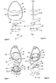
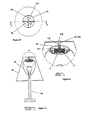
- the housing 1 comprises a transparent portion 4 to allow light to enter the housing 1 and the housing 1 has a coupling arrangement 5 for releasably coupling the housing 1 onto the light fitting 3.
- the housing 1 has a housing wall 6 with one aperture 7.
- the aperture 7 provides a means for coupling the transducer 2 to external mobiles 8, see figures 9 to 16 .
- the housing 1 has a support arrangement 11 provided by an internal wall of the housing 6 for supporting the transducer 2 so as to direct the solar to electric transducer 2 towards light from the transparent portion 4 of the housing 1.
- the transparent portion 4 forms a minor part of the housing 1 as is the case in the embodiment shown in the drawings.
- the transparent portion 4 is dimensioned to allow a predetermined amount of light into the housing 1 sufficient to drive a motor 14 which is electrically and mechanically connected to the transducer 2.
- the entire housing 1 is manufactured from a transparent material. It will of course be appreciated that a housing 1 with any appropriate proportion of transparent to opaque material can be manufactured to suit specific housing applications or designs.
- the housing 1 is formed for substantially enclosing the solar to electric transducer 2.
- the transducer 2 is capable of converting a portion of the existing light energy from a light source 51 such as a bulb 51 into useful electrical energy which is otherwise unused dissipating into the atmosphere.
- the housing 1 is designed to hide internal components such as the transducer 2 and the motor 14 from view in normal use.
- the solar to electric transducer 2 is coupled to an actuator 14 which is powered by the electrical energy generated by the solar to electric transducer 2 and the actuator 14 is a suitably sized motor 14 depending on the specification of the transducer 2 and the mobiles 8.
- the housing 1 is manufactured in the form of a separable pod 15 having a window 16 for receiving light.
- the separable pod 15 comprises a pair of similar shallow dishes 17 see figures 5 to 8 , one of which is Inverted and releasably coupled together with the other 17 along their opposing rims 18, which are preferably formed for snap fit engagement.
- One of the dishes 17 has a window opening 19 formed for receiving a transparent window section 21.
- the transparent window section 21 has an outer convex curved surface 22 corresponding to the outer convex curved surface 23 of the dish 17 with the window opening 19 so as to maintain the integrity of the elliptical appearance of the pod 15 when the window section 21 is fitted in the window opening 19.
- the dish 17 opposing the window opening 19 has a retaining arrangement 25 for retaining the window section 21 in place in the window opening 19 when the pod 15 is assembled.
- the retaining arrangement 25 has four spaced apart struts 27 extending from the opposing dish 17 to engage recesses 31 correspondingly spaced apart along the perimeter of the window section 21 so as to force the window section 21 into a lip 28 of the window opening 19 when the pod 15 is assembled.
- the coupling arrangement 5 is a coupling support frame 5, see Figures 1 to 4 .
- the coupling support frame 5 is preferably separate to any lampshade support frame 62.
- the coupling support frame 5 has a wire frame 34 having a first member 35 connected to a light fitting 3 see Figures 9 to 16 and a pair of arms 36 extending between the first member 35 and both sides of the housing 1. The end of each arm 36 is retained within the housing 1.
- the housing 1 has fasteners 37 for fastening the free end 38 of each arm 36 thereto when the pod 15 is assembled.
- Each dish 17 has a pair of fastener members 37 on opposing locations of the perimeter of the dish 17, Male fastener members 41 are provided on one dish 17 and female fastener members 42 are provided on the other dish 17. It will of course be appreciated that one male fastener member 42 and one female fastener member 42 may be mounted on each dish 17.
- the fastener members 41, 42 are provided at diametrically opposed locations of each dish 17,
- the housing 1 also has a solar to electric transducer 2 and motor housing 44 mounted on the support arrangement 11.
- the housing 1 also has location members 45 see Figures 7 and 8 for locating the motor housing 44 thereon.
- the location members 45 comprises a pair of spigots 45 extending from the internal concave wall 6 of one dish 17 and being formed for engagement with correspondingly located sockets 46 on the motor housing 44.
- the housing aperture 7 is formed for substantial alignment with a motor driveshaft 47 when the motor housing 44 Is located in the housing 1 via the location members 45.
- An attachment member 71 such as a hook can be connected to the driveshaft 47 to allow a range of mobiles 8 to be readily added or removed from the hook 71.
- the motor drive shaft 47 is operably engaged with mobiles 8 via the aperture 7 of the housing wall 6.
- the motor housing 44 is mounted on the housing wall 6 of the housing 1 and the solar to electric transducer 2 is mounted on top of the motor housing 44 facing a transparent portion 4 of the housing 1.
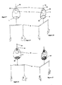
- the housing 1 can be attached to a pendant type light fitting 3, see Figures 9 to 16 , a table lamp or a floor lamp see Figures 17 to 18 , a pendant centre light or a recessed light, not shown.
- the light source is a bulb 51 and is mounted in the light fitting comprising a bulb holder 52 and preferably a locking cap 53.
- the housing 1 for the solar to electric transducer 2 is mountable on or about the mechanical support for the light source such as on top of the bulb holder 52 or alternatively mountable to the cable 54 conducting the electricity.
- the transducer 2 is provided by at least one photo voltaic solar cell 2 for converting solar to electrical energy.
- the transducer 2 is located in the housing 1 for collecting at least a portion of the light from a powered light source 51 mounted in the light fitting 3.
- the transducer 2 is also capable of collecting at least some of the light from the sun and converting a portion of the existing sunlight energy into useful electrical energy which is otherwise unused.
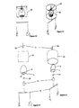
- a lampshade 61 see Figures 13 to 16 having a generally cylindrical wire support frame 62 covered in a partially transparent material 63 for partially transmitting light from the light source 51 is separately attached to the same light fitting 3.
- the shape of the wire support frame 62 is described as generally cylindrical, it will of course be appreciated that any well known shape of lamp shade can be used with the present invention such as hemispherical or frusto-conical.
- a centre light fitting having a housing for a solar powered transducer attached to each of the separate light fittings of the centre light fitting.
- the rotational motion of the motor 14 can be converted into linear motion.
- At least a portion of the decorative mobile 8 can be moved in a straight line relative to the housing 1/lampshade 61.
- the linear motion can be applied to mobiles 8 on the lampshade 61 to provide the effect of characters moving up and down on the lampshade 61, internally or externally.
- the housing 1 In use, when the housing 1 is connected to a light fitting 3 such as a conventional bulb holder 52 and the light is switched on the solar cell transducer 2 converts some of the solar energy into electrical energy.
- the electrical energy powers the motor 14 causing the drive shaft 47 to rotate.
- the drive shaft 47 acts on the hook 71 which is connected to the mobile 8 causing the mobile 8 to rotate relative to the housing 1.
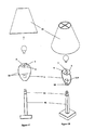
- the housing 1 for a solar to electric transducer 2 to be coupled to a table or floor lamp 91.
- the housing 1 has the transparent portion 4 to allow light into the housing 1 and a coupling arrangement 5 for releasably coupling the housing 1 onto the light fitting 93 of the table/floor lamp 91.
- the housing 1 has a housing wall 6 with one aperture 7.
- the aperture 7 provides a passageway for a motor driveshaft 96 for coupling the transducer 2 to a lampshade 94.
- the wire frame 97 of the lampshade 94 comprises support member 98 at the top end of the wire frame 97 and the support member 98 has a central closed loop member 99 defining an aperture 101.
- the connector 95 is provided by a plug 102 having a first end 103 formed for engagement with the central aperture 101 and a second end formed for operably engaging a free end of the drive shaft 96 of the motor 14.
- the central closed loop member 99 is provided by a 10 mm washer although a range of diameters is encompassed by the present invention.
- the support member 98 is provided by a cross hair arrangement intersecting at the washer.
- the second end of the plug 102 is formed with a blind bore 104 for operably engaging a free end of the drive shaft 96.
- the free end of the drive shaft 96 of the motor 14 can be roughened by knurling for example to frictionally engage the blind bore 103.
- the plug 102 is a molded part preferably manufactured form a durable plastics material.
- the coupling arrangement 5 is the same coupling support frame 5 as described in relation to the earlier embodiments having a wire frame 34 with a first member 35 connected to the light fitting 93 such as a standard bulb holder and preferably a locking cap 114.
- a pair of arms 36 extend between the first member 35 and both sides of the housing 1. The end of each arm 36 is retained within the housing 1.
- the housing 1 In use, when the housing 1 is connected to a table/floor lamp 93 by mounting the first member 35 onto the conventional bulb holder 93 and the light is switched on the solar cell transducer 2 converts some of the solar energy into electrical energy.
- the electrical energy powers the motor 14 causing the drive shaft 96 to rotate.
- the drive shaft 96 acts on the plug 102 which is connected to the lampshade 94 causing the lampshade to rotate relative to the housing 1.
Landscapes
- Engineering & Computer Science (AREA)
- General Engineering & Computer Science (AREA)
- Arrangement Of Elements, Cooling, Sealing, Or The Like Of Lighting Devices (AREA)
- Non-Portable Lighting Devices Or Systems Thereof (AREA)
Applications Claiming Priority (1)
| Application Number | Priority Date | Filing Date | Title |
|---|---|---|---|
| IE20100716 | 2010-11-11 |
Publications (2)
| Publication Number | Publication Date |
|---|---|
| EP2453166A2 true EP2453166A2 (de) | 2012-05-16 |
| EP2453166A3 EP2453166A3 (de) | 2014-04-02 |
Family
ID=45047531
Family Applications (1)
| Application Number | Title | Priority Date | Filing Date |
|---|---|---|---|
| EP11008976.0A Withdrawn EP2453166A3 (de) | 2010-11-11 | 2011-11-11 | Gehäuse für einen solarbetriebenen Wandler |
Country Status (1)
| Country | Link |
|---|---|
| EP (1) | EP2453166A3 (de) |
Cited By (2)
| Publication number | Priority date | Publication date | Assignee | Title |
|---|---|---|---|---|
| GB2489444A (en) * | 2011-03-28 | 2012-10-03 | Hackett Dominic A | Lighting arrangement |
| EP2521877B1 (de) * | 2009-11-30 | 2017-07-12 | Hackett, Domnic Anthony | Beleuchtungsanordnung und beweglicher lampenschirm |
Family Cites Families (8)
| Publication number | Priority date | Publication date | Assignee | Title |
|---|---|---|---|---|
| US4376347A (en) * | 1981-09-18 | 1983-03-15 | Thompson Marion E | Light powered mobile |
| US4772990A (en) * | 1986-08-26 | 1988-09-20 | Cni | Solar powered warning flasher |
| DE3700045A1 (de) * | 1987-01-02 | 1988-07-14 | Berthold Heyne | Lampe |
| FR2726629B1 (fr) * | 1994-11-07 | 1997-01-10 | Varale Henri | Lampes et autres systemes a abat-jour tournant |
| US7259536B1 (en) * | 2005-06-17 | 2007-08-21 | Ketner Cheryl L | Solar powered mobile |
| CN200979101Y (zh) * | 2006-08-28 | 2007-11-21 | 深圳市宝安区松岗拓实制品厂 | 灯饰 |
| US7972030B2 (en) * | 2007-03-05 | 2011-07-05 | Intematix Corporation | Light emitting diode (LED) based lighting systems |
| GB2475747B (en) * | 2009-11-30 | 2011-12-14 | Domnic Anthony Hackett | A lighting arrangement and a movable lampshade |
-
2011
- 2011-11-11 EP EP11008976.0A patent/EP2453166A3/de not_active Withdrawn
Non-Patent Citations (1)
| Title |
|---|
| None |
Cited By (2)
| Publication number | Priority date | Publication date | Assignee | Title |
|---|---|---|---|---|
| EP2521877B1 (de) * | 2009-11-30 | 2017-07-12 | Hackett, Domnic Anthony | Beleuchtungsanordnung und beweglicher lampenschirm |
| GB2489444A (en) * | 2011-03-28 | 2012-10-03 | Hackett Dominic A | Lighting arrangement |
Also Published As
| Publication number | Publication date |
|---|---|
| EP2453166A3 (de) | 2014-04-02 |
Similar Documents
| Publication | Publication Date | Title |
|---|---|---|
| CN214948735U (zh) | 一种太阳能灯具 | |
| CA2202341A1 (en) | Rechargeable flashlight assembly with nightlight | |
| CN201081136Y (zh) | 一种带防水插座的大功率led太阳能草坪灯 | |
| EP2521877B1 (de) | Beleuchtungsanordnung und beweglicher lampenschirm | |
| EP4119837A1 (de) | Lüfterlampe | |
| EP3087307B1 (de) | Die erfindung betrifft eine led-leuchte | |
| CN213394824U (zh) | 一种防水型灯具 | |
| EP2453166A2 (de) | Gehäuse für einen solarbetriebenen Wandler | |
| USD493769S1 (en) | Solar sun rescue reflector charger kit | |
| CA3140400A1 (en) | Solar string light and socket assembly | |
| CN201983091U (zh) | 旋转式小夜灯 | |
| WO2011024643A1 (ja) | 可搬型照明装置 | |
| CN210637930U (zh) | 照明装置 | |
| JP3174017U (ja) | ソーラーライト | |
| CN213394876U (zh) | —种安装角度可调的且方便开启电源盒的led灯 | |
| CN210197159U (zh) | 一种具有防眩效果的led投光灯 | |
| US11873972B2 (en) | Solar coach light | |
| JP2011198613A (ja) | 可搬型照明装置 | |
| CN214172021U (zh) | 一种可变换角度的灯具 | |
| CN223840229U (en) | Lamp set | |
| CN211976584U (zh) | 一种便捷式角度可调头灯 | |
| CN217503523U (zh) | 一种太阳能射灯 | |
| CN221074683U (zh) | 一种便携式露营风扇 | |
| CN214535943U (zh) | 灯具 | |
| CN218863913U (zh) | 一种野营灯 |
Legal Events
| Date | Code | Title | Description |
|---|---|---|---|
| PUAI | Public reference made under article 153(3) epc to a published international application that has entered the european phase |
Free format text: ORIGINAL CODE: 0009012 |
|
| AK | Designated contracting states |
Kind code of ref document: A2 Designated state(s): AL AT BE BG CH CY CZ DE DK EE ES FI FR GB GR HR HU IE IS IT LI LT LU LV MC MK MT NL NO PL PT RO RS SE SI SK SM TR |
|
| AX | Request for extension of the european patent |
Extension state: BA ME |
|
| PUAL | Search report despatched |
Free format text: ORIGINAL CODE: 0009013 |
|
| AK | Designated contracting states |
Kind code of ref document: A3 Designated state(s): AL AT BE BG CH CY CZ DE DK EE ES FI FR GB GR HR HU IE IS IT LI LT LU LV MC MK MT NL NO PL PT RO RS SE SI SK SM TR |
|
| AX | Request for extension of the european patent |
Extension state: BA ME |
|
| RIC1 | Information provided on ipc code assigned before grant |
Ipc: A63H 29/22 20060101ALI20140226BHEP Ipc: F21S 9/03 20060101ALI20140226BHEP Ipc: F21S 8/06 20060101AFI20140226BHEP Ipc: F21V 33/00 20060101ALI20140226BHEP |
|
| RBV | Designated contracting states (corrected) |
Designated state(s): AL AT BE BG CH CY CZ DE DK EE ES FI FR GB GR HR HU IE IS IT LI LT LU LV MC MK MT NL NO PL PT RO RS SE SI SK SM TR |
|
| 17P | Request for examination filed |
Effective date: 20140925 |
|
| 17Q | First examination report despatched |
Effective date: 20150302 |
|
| STAA | Information on the status of an ep patent application or granted ep patent |
Free format text: STATUS: THE APPLICATION IS DEEMED TO BE WITHDRAWN |
|
| 18D | Application deemed to be withdrawn |
Effective date: 20150714 |