EP2453104A1 - Bohrlochvorrichtung - Google Patents
Bohrlochvorrichtung Download PDFInfo
- Publication number
- EP2453104A1 EP2453104A1 EP10797365A EP10797365A EP2453104A1 EP 2453104 A1 EP2453104 A1 EP 2453104A1 EP 10797365 A EP10797365 A EP 10797365A EP 10797365 A EP10797365 A EP 10797365A EP 2453104 A1 EP2453104 A1 EP 2453104A1
- Authority
- EP
- European Patent Office
- Prior art keywords
- well
- seal
- housing
- segments
- cavity
- Prior art date
- Legal status (The legal status is an assumption and is not a legal conclusion. Google has not performed a legal analysis and makes no representation as to the accuracy of the status listed.)
- Withdrawn
Links
- 238000007789 sealing Methods 0.000 claims abstract description 15
- 230000015572 biosynthetic process Effects 0.000 claims abstract description 14
- 238000009434 installation Methods 0.000 claims abstract description 8
- 230000003993 interaction Effects 0.000 claims abstract description 5
- 238000000926 separation method Methods 0.000 claims abstract description 4
- 239000000463 material Substances 0.000 claims description 4
- 239000012530 fluid Substances 0.000 abstract description 7
- 238000005553 drilling Methods 0.000 abstract description 3
- 230000001419 dependent effect Effects 0.000 abstract 1
- 238000011112 process operation Methods 0.000 description 8
- 230000009471 action Effects 0.000 description 4
- 230000008878 coupling Effects 0.000 description 3
- 238000010168 coupling process Methods 0.000 description 3
- 238000005859 coupling reaction Methods 0.000 description 3
- 230000000712 assembly Effects 0.000 description 2
- 238000000429 assembly Methods 0.000 description 2
- 238000010009 beating Methods 0.000 description 2
- 239000004519 grease Substances 0.000 description 2
- 125000006850 spacer group Chemical group 0.000 description 2
- 238000005381 potential energy Methods 0.000 description 1
- 230000002265 prevention Effects 0.000 description 1
- 230000009467 reduction Effects 0.000 description 1
- 230000000717 retained effect Effects 0.000 description 1
Images


Classifications
-
- E—FIXED CONSTRUCTIONS
- E21—EARTH OR ROCK DRILLING; MINING
- E21B—EARTH OR ROCK DRILLING; OBTAINING OIL, GAS, WATER, SOLUBLE OR MELTABLE MATERIALS OR A SLURRY OF MINERALS FROM WELLS
- E21B33/00—Sealing or packing boreholes or wells
- E21B33/10—Sealing or packing boreholes or wells in the borehole
- E21B33/12—Packers; Plugs
-
- E—FIXED CONSTRUCTIONS
- E21—EARTH OR ROCK DRILLING; MINING
- E21B—EARTH OR ROCK DRILLING; OBTAINING OIL, GAS, WATER, SOLUBLE OR MELTABLE MATERIALS OR A SLURRY OF MINERALS FROM WELLS
- E21B34/00—Valve arrangements for boreholes or wells
- E21B34/06—Valve arrangements for boreholes or wells in wells
- E21B34/14—Valve arrangements for boreholes or wells in wells operated by movement of tools, e.g. sleeve valves operated by pistons or wire line tools
Definitions
- the invention pertains to the oil and gas industry and can be used in technical operations relating to well completion.
- the known downhole shutoff devices are characterized by the significant reduction of flow channel diameter compared to the producing well diameter.
- the rotating universal hydraulic preventer containing a housing with a cavity and a central opening, a cover with an opening, bearings, a shell, a sealing element located in the shell RU No. 2208126 C2 , E21B33/06, 10.07.2003; RU No. 2013519 C1 , E21B33/06, 30.05.1994; RU No. 45770 U1 , E21B33/06, 27.05.2005.
- the known rotating preventers which are installed on the well opening, have overall dimensions significantly exceeding the well diameter; they do not completely overlap the cross-section.
- a rotating preventer containing a housing, a bearing assembly, a shaft rotating in the bearing assembly and a sealing device connected with the well equipment, RU No. 2341643 C1 , E21B33/06, 20.12.2008.
- the sealing device of the "closest analog" preventer is made in the form of a spacer ring with a groove on the inner surface and is located on the coupling connecting the drill string and the kelly stem.
- the groove in the spacer ring is connected with the inner cavity of the coupling.
- the sealing device of the "closest analog” preventer seals the well opening during drilling operations and such sealing is possible only under action of drill fluid, which limits execution of other process operations.
- the "closest analog” preventer belongs to devices that seal the well opening during drilling.
- this problem is solved by using a borehole device containing a housing; a bearing assembly; and a sealing device connected with the borehole equipment.
- the device acts as a sealing device by using a seal.
- the seal separates the well into the upper and lower cavity with the presence of hydraulic connection between the well opening and the upper cavity and between the lower cavity and the producing formation respectively.
- the seal has a collet with segments in the lower part and is made capable of separating at interaction with the well equipment, is equipped with additional seals on lateral surfaces, a liner on external surfaces, springs and casing located in the lower part and providing arrangement of segments during their separation.
- the seal is located in the housing provided with the upper thread and fastened in the beating assembly.
- the device further includes an adjustment insert that is capable of interacting with the well equipment upon the installation thereof and of moving same so as to open the channel of a hydraulic connection between the well opening, the upper cavity, the lower cavity and the producing formation.
- the invention is characterized by a number of optional features, namely:
- the invention meets the "novelty" (N) criterion.
- the immediate technical result is implementation of technical operations on well completion without creation of overbalance on the productive deposits by the washer fluid column, with the help of the suggested device made as a sealing device by means of the seal separating the well into the upper and lower cavities, containing the collet with segments in the lower part capable of separating at interaction with the well equipment and located in the housing fastened in the bearing assembly.
- the downhole device contains:
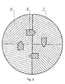
- the borehole device contains a housing (1), bearing assembly (4) and seal (5).
- the device acts as a sealing device by using a seal (5).
- the seal (5) separates the well into the upper (16) and the lower (17) cavity with the presence of hydraulic connection between the well opening and the upper cavity and between the lower cavity and the producing formation respectively.
- the seal (5) contains a funnel-shaped collet (7).
- the collet (7) in the encasing (6) in the lower part contains segments (8) closely fitting to each other, capable of separating and equipped with the additional seals (9) on the lateral surfaces.
- the collet (7) contains a liner (10) on its external surfaces.
- the liner (10) is made of a strong flexible material.
- the collet (7) contains springs (11).
- the encasing (6) is located in the lower part of the collet (7) providing arrangement of segments (8) during their separation.
- the space between the seal (5) and the encasing (6) is filled with grease.
- the seal (5) is located in the housing (1) provided with the upper thread (2) and fastened in the beating assembly.
- the bearing assembly contains the oil-filled sealed bearing (4).
- the lower thread (3) is made on the housing (1) for installation of the device between the pipes of the casing string (18), if necessary.
- the device further includes an adjustment insert (12).
- the adjustment insert (12) is capable of interacting with the well equipment during its installation, for example, with the drill string (19), and of moving the same so as to open the channel of a hydraulic connection (13) between the well opening, the upper cavity, the lower cavity and the producing formation.
- the device is additionally equipped with the drill-through cover (14).
- the drill-through cover (14) is made of easily drillable material, for example, 16.
- the locating insert (12) in installed in the seal (5).
- the space between the seal (5) and the encasing (6) is filled with grease to prevent crushing of the encasing (6) under external pressure during lowering of the device into the well (15).
- the housing (1) of the device is connected by means of the upper thread (2) and the lower thread (3) with the pipe of the string (18) located below.
- the casing string (18) together with the device is lowered into the well.
- the drill string (19) is lowered down to the device and the locating insert (12) is pushed out by subsequent pressing, thus breaking the drill-through cover (14).
- Segments (8) of the collet (7) are separated and the channels of the hydraulic connection (13) between the well opening, the upper cavity, the lower cavity and the producing formation open.
- the encasing (6) provides the guaranteed space for location of the separated segments (8).
- the drill string (19) is lowered down to the productive deposits.
- the drill string (19) is lowered in the similar way through the device.
- the device supports their installation and operation in the required modes.
- Availability of the collet in the seal which provides interaction with the well equipment and opening of the channel of the hydraulic connection between the well opening, the upper cavity, the lower cavity and the producing formation prevents inflow of formation fluids, when necessary.
- the suggested downhole device can be used during execution of the process operations on the well completion without loss of flow channel diameter by more than the normative value, during prevention of the formation fluids inflow and during application of the known parts and assemblies manufactured industrially and widely used in the oil and gas producing industry, and the research, development and testing of the experimental batches confirme, in the applicant's opinion, its compliance with the "industrial applicability" (IA) criterion.
- IA industrial applicability
Landscapes
- Geology (AREA)
- Life Sciences & Earth Sciences (AREA)
- Engineering & Computer Science (AREA)
- Mining & Mineral Resources (AREA)
- Environmental & Geological Engineering (AREA)
- Fluid Mechanics (AREA)
- Physics & Mathematics (AREA)
- General Life Sciences & Earth Sciences (AREA)
- Geochemistry & Mineralogy (AREA)
- Earth Drilling (AREA)
- Sealing Devices (AREA)
- Consolidation Of Soil By Introduction Of Solidifying Substances Into Soil (AREA)
- Laying Of Electric Cables Or Lines Outside (AREA)
Applications Claiming Priority (2)
| Application Number | Priority Date | Filing Date | Title |
|---|---|---|---|
| RU2009126485 | 2009-07-10 | ||
| PCT/RU2010/000294 WO2011005144A1 (ru) | 2009-07-10 | 2010-06-07 | Устройство внутрискважинное |
Publications (1)
| Publication Number | Publication Date |
|---|---|
| EP2453104A1 true EP2453104A1 (de) | 2012-05-16 |
Family
ID=43429390
Family Applications (1)
| Application Number | Title | Priority Date | Filing Date |
|---|---|---|---|
| EP10797365A Withdrawn EP2453104A1 (de) | 2009-07-10 | 2010-06-07 | Bohrlochvorrichtung |
Country Status (13)
| Country | Link |
|---|---|
| US (1) | US20120132429A1 (de) |
| EP (1) | EP2453104A1 (de) |
| KR (1) | KR20120048622A (de) |
| CN (1) | CN102482929B (de) |
| BR (1) | BR112012000580A2 (de) |
| CA (1) | CA2767197A1 (de) |
| CL (1) | CL2012000067A1 (de) |
| EA (1) | EA020796B1 (de) |
| IN (1) | IN2012DN00916A (de) |
| MX (1) | MX2012000004A (de) |
| PE (1) | PE20121203A1 (de) |
| UA (1) | UA105797C2 (de) |
| WO (1) | WO2011005144A1 (de) |
Families Citing this family (1)
| Publication number | Priority date | Publication date | Assignee | Title |
|---|---|---|---|---|
| US9470055B2 (en) | 2012-12-20 | 2016-10-18 | Schlumberger Technology Corporation | System and method for providing oscillation downhole |
Family Cites Families (35)
| Publication number | Priority date | Publication date | Assignee | Title |
|---|---|---|---|---|
| SU874993A1 (ru) * | 1979-06-15 | 1981-10-23 | Особое Конструкторское Бюро По Проектированию Нефтегазодобывающих Машин И Оборудования Министерства Химического И Нефтяного Машиностроения | Скважинный клапан-отсекатель |
| RU2027847C1 (ru) | 1990-12-06 | 1995-01-27 | Северо-Кавказский научно-исследовательский институт природных газов | Вращающийся превентор |
| RU2013519C1 (ru) | 1991-03-28 | 1994-05-30 | Павел Леонтьевич Пшеничный | Универсальный превентор пшеничного |
| RU2021490C1 (ru) | 1991-05-05 | 1994-10-15 | Особое конструкторское бюро по проектированию нефтегазодобывающих машин и оборудования | Скважинный клапан-отсекатель |
| RU2011797C1 (ru) | 1992-01-27 | 1994-04-30 | Владимир Федорович Францев | Скважинный клапан-отсекатель |
| RU2160357C2 (ru) | 1994-06-02 | 2000-12-10 | Фирма "Саратовгазприборавтоматика" | Клапан-отсекатель |
| RU2094593C1 (ru) | 1995-03-07 | 1997-10-27 | Татарский научно-исследовательский и проектный институт нефти | Клапан-отсекатель |
| RU2112863C1 (ru) | 1996-01-09 | 1998-06-10 | Владимир Федорович Францев | Скважинный клапан отсекатель |
| RU2107152C1 (ru) | 1996-01-09 | 1998-03-20 | Владимир Федорович Францев | Скважинный клапан-отсекатель |
| RU2125643C1 (ru) | 1997-04-04 | 1999-01-27 | Военизированная противофонтанная часть "Лiкво" | Превентор |
| RU2145024C1 (ru) | 1998-01-09 | 2000-01-27 | Кузаев Григорий Иванович | Клапан-отсекатель |
| RU2169829C1 (ru) | 1999-11-16 | 2001-06-27 | Открытое акционерное общество Научно-производственное объединение Роснефть-Термнефть | Универсальный внутрискважинный клапан-отсекатель |
| RU2172815C1 (ru) | 2000-03-14 | 2001-08-27 | Закрытое акционерное общество завод "Измерон" | Клапан-отсекатель |
| RU2208126C2 (ru) | 2001-01-29 | 2003-07-10 | Федеральное государственное унитарное предприятие "Воронежский механический завод" | Вращающийся универсальный гидравлический превентор |
| RU22174U1 (ru) | 2001-03-11 | 2002-03-10 | Кузаев Григорий Иванович | Клапан-отсекатель |
| RU2224087C2 (ru) | 2002-04-22 | 2004-02-20 | Открытое акционерное общество "Акционерная нефтяная компания "Башнефть" | Скважинный клапан-отсекатель |
| RU25527U1 (ru) | 2002-05-17 | 2002-10-10 | Закрытое акционерное общество завод "Измерон" | Скважинное клапанное устройство |
| WO2004031532A1 (en) * | 2002-10-02 | 2004-04-15 | Baker Hugues Incorporated | Mono-trip well completion |
| US7451809B2 (en) * | 2002-10-11 | 2008-11-18 | Weatherford/Lamb, Inc. | Apparatus and methods for utilizing a downhole deployment valve |
| US7836946B2 (en) * | 2002-10-31 | 2010-11-23 | Weatherford/Lamb, Inc. | Rotating control head radial seal protection and leak detection systems |
| RU2234595C1 (ru) | 2002-12-30 | 2004-08-20 | Общество с ограниченной ответственностью "Подземгазпром" | Скважинный клапан-отсекатель |
| RU32183U1 (ru) | 2003-01-30 | 2003-09-10 | Закрытое акционерное общество завод "Измерон" | Клапанное устройство для буровой колонны труб |
| RU2250354C2 (ru) * | 2003-05-05 | 2005-04-20 | Открытое акционерное общество "Научно-производственное объединение "Бурение" | Стационарный проходной клапан-отсекатель |
| RU37762U1 (ru) | 2004-01-08 | 2004-05-10 | Открытое акционерное общество "Татнефть" им. В.Д.Шашина | Превентор |
| US7240727B2 (en) * | 2004-02-20 | 2007-07-10 | Williams John R | Armored stripper rubber |
| RU2304693C2 (ru) | 2004-05-18 | 2007-08-20 | Николай Александрович Михеев | Превентор |
| RU45770U1 (ru) | 2004-12-02 | 2005-05-27 | ОАО НПО "Буровая техника" | Универсальный вращающийся превентор |
| RU2311526C2 (ru) | 2005-09-08 | 2007-11-27 | Открытое акционерное общество "Научно-производственное объединение "Бурение" | Клапан-отсекатель |
| RU2293839C1 (ru) | 2005-09-21 | 2007-02-20 | Владимир Васильевич Торопынин | Клапан-отсекатель |
| US7836973B2 (en) * | 2005-10-20 | 2010-11-23 | Weatherford/Lamb, Inc. | Annulus pressure control drilling systems and methods |
| CN2906024Y (zh) * | 2005-11-23 | 2007-05-30 | 中国石化集团中原石油勘探局钻井工程技术研究院 | 一种流道贯通遥控变径稳定器 |
| RU2312203C2 (ru) | 2006-02-03 | 2007-12-10 | Илья Вадимович Неудачин | Клапан-отсекатель |
| RU2341643C1 (ru) | 2007-03-19 | 2008-12-20 | Федеральное государственное образовательное учреждение высшего профессионального образования "Сибирский Федеральный университет", (СФУ) | Вращающийся превентор |
| CN201165861Y (zh) * | 2008-01-25 | 2008-12-17 | 毛万里 | 油田井下流体控制阀及开关工具 |
| RU76961U1 (ru) | 2008-05-12 | 2008-10-10 | Федеральное государственное образовательное учреждение высшего профессионального образования Сибирский федеральный университет (СФУ) | Вращающийся превентор |
-
2010
- 2010-06-07 WO PCT/RU2010/000294 patent/WO2011005144A1/ru not_active Ceased
- 2010-06-07 BR BR112012000580A patent/BR112012000580A2/pt not_active IP Right Cessation
- 2010-06-07 CN CN201080030926.5A patent/CN102482929B/zh not_active Expired - Fee Related
- 2010-06-07 UA UAA201201386A patent/UA105797C2/uk unknown
- 2010-06-07 MX MX2012000004A patent/MX2012000004A/es unknown
- 2010-06-07 EA EA201200108A patent/EA020796B1/ru not_active IP Right Cessation
- 2010-06-07 EP EP10797365A patent/EP2453104A1/de not_active Withdrawn
- 2010-06-07 US US13/382,999 patent/US20120132429A1/en not_active Abandoned
- 2010-06-07 CA CA2767197A patent/CA2767197A1/en not_active Abandoned
- 2010-06-07 KR KR1020127003645A patent/KR20120048622A/ko not_active Ceased
- 2010-06-07 PE PE2012000014A patent/PE20121203A1/es not_active Application Discontinuation
-
2012
- 2012-01-10 CL CL2012000067A patent/CL2012000067A1/es unknown
- 2012-02-01 IN IN916DEN2012 patent/IN2012DN00916A/en unknown
Non-Patent Citations (1)
| Title |
|---|
| See references of WO2011005144A1 * |
Also Published As
| Publication number | Publication date |
|---|---|
| EA201200108A1 (ru) | 2012-06-29 |
| US20120132429A1 (en) | 2012-05-31 |
| CA2767197A1 (en) | 2011-01-13 |
| CL2012000067A1 (es) | 2013-02-08 |
| MX2012000004A (es) | 2012-10-03 |
| PE20121203A1 (es) | 2012-09-28 |
| IN2012DN00916A (de) | 2015-04-03 |
| WO2011005144A1 (ru) | 2011-01-13 |
| EA020796B1 (ru) | 2015-01-30 |
| BR112012000580A2 (pt) | 2019-09-24 |
| CN102482929B (zh) | 2014-04-02 |
| KR20120048622A (ko) | 2012-05-15 |
| CN102482929A (zh) | 2012-05-30 |
| UA105797C2 (uk) | 2014-06-25 |
Similar Documents
| Publication | Publication Date | Title |
|---|---|---|
| CN106968646B (zh) | 完井装置 | |
| US11371312B2 (en) | Cup plug having a large flow-through inside diameter | |
| CN104011320B (zh) | 井下桥塞下入工具 | |
| EP2322758B1 (de) | Schuttsperre für Bohrwerkzeuge | |
| NO325056B1 (no) | Null-boringskomplettering og produksjonssystem | |
| CN107387050A (zh) | 一种投球式全通径压裂滑套 | |
| US11492861B2 (en) | Packer assembly for use within a borehole | |
| EP2248991A2 (de) | Fernbedientes Bohrgestängeventil | |
| EP2885487B1 (de) | Druckaktivierte bohrlochsysteme und verfahren | |
| AU2014401769B2 (en) | Downhole ball valve | |
| EP4399386B1 (de) | Schlauchkopfspule mit adapterbuchse | |
| EP2453104A1 (de) | Bohrlochvorrichtung | |
| US11118423B1 (en) | Downhole tool for use in a borehole | |
| CN204703840U (zh) | 贯眼完井用免钻塞分级注水泥器 | |
| RU2386012C1 (ru) | Устройство для манжетного цементирования скважины | |
| RU88732U1 (ru) | Устройство внутрискважинное | |
| CN104895523A (zh) | 贯眼完井用免钻塞分级注水泥器 | |
| RU2425946C1 (ru) | Скважинный разъединитель | |
| CN113631794A (zh) | 用于封隔器的防提前坐封 | |
| CN104265231A (zh) | 循环堵塞器及其使用方法 | |
| US8763707B2 (en) | Downhole circulating valve having a metal-to-metal seal | |
| US9388663B2 (en) | Downhole circulating valve having a metal-to-metal seal and method for operating same | |
| RU119797U1 (ru) | Устройство для герметизации устья скважины при бурении обсадными трубами | |
| WO2013151534A1 (en) | Downhole circulating valve having a metal-to-metal seal and method for operating same |
Legal Events
| Date | Code | Title | Description |
|---|---|---|---|
| PUAI | Public reference made under article 153(3) epc to a published international application that has entered the european phase |
Free format text: ORIGINAL CODE: 0009012 |
|
| 17P | Request for examination filed |
Effective date: 20120208 |
|
| AK | Designated contracting states |
Kind code of ref document: A1 Designated state(s): AL AT BE BG CH CY CZ DE DK EE ES FI FR GB GR HR HU IE IS IT LI LT LU LV MC MK MT NL NO PL PT RO SE SI SK SM TR |
|
| DAX | Request for extension of the european patent (deleted) | ||
| STAA | Information on the status of an ep patent application or granted ep patent |
Free format text: STATUS: THE APPLICATION IS DEEMED TO BE WITHDRAWN |
|
| 18D | Application deemed to be withdrawn |
Effective date: 20150106 |