EP2452786A1 - Structural support for power tool housings - Google Patents
Structural support for power tool housings Download PDFInfo
- Publication number
- EP2452786A1 EP2452786A1 EP12154260A EP12154260A EP2452786A1 EP 2452786 A1 EP2452786 A1 EP 2452786A1 EP 12154260 A EP12154260 A EP 12154260A EP 12154260 A EP12154260 A EP 12154260A EP 2452786 A1 EP2452786 A1 EP 2452786A1
- Authority
- EP
- European Patent Office
- Prior art keywords
- tool housing
- motor
- junction
- reinforcing ring
- tool
- Prior art date
- Legal status (The legal status is an assumption and is not a legal conclusion. Google has not performed a legal analysis and makes no representation as to the accuracy of the status listed.)
- Withdrawn
Links
- 230000003014 reinforcing effect Effects 0.000 claims description 41
- 239000000463 material Substances 0.000 description 3
- 239000002184 metal Substances 0.000 description 3
- VYZAMTAEIAYCRO-UHFFFAOYSA-N Chromium Chemical compound [Cr] VYZAMTAEIAYCRO-UHFFFAOYSA-N 0.000 description 2
- 239000003610 charcoal Substances 0.000 description 2
- 229910000831 Steel Inorganic materials 0.000 description 1
- 210000000988 bone and bone Anatomy 0.000 description 1
- ZPUCINDJVBIVPJ-LJISPDSOSA-N cocaine Chemical compound O([C@H]1C[C@@H]2CC[C@@H](N2C)[C@H]1C(=O)OC)C(=O)C1=CC=CC=C1 ZPUCINDJVBIVPJ-LJISPDSOSA-N 0.000 description 1
- 239000002131 composite material Substances 0.000 description 1
- 230000006835 compression Effects 0.000 description 1
- 238000007906 compression Methods 0.000 description 1
- 238000001816 cooling Methods 0.000 description 1
- 238000005336 cracking Methods 0.000 description 1
- -1 for example Substances 0.000 description 1
- 239000004519 grease Substances 0.000 description 1
- 238000000034 method Methods 0.000 description 1
- 238000012986 modification Methods 0.000 description 1
- 230000004048 modification Effects 0.000 description 1
- 238000000465 moulding Methods 0.000 description 1
- 239000004033 plastic Substances 0.000 description 1
- 229920003023 plastic Polymers 0.000 description 1
- 239000002990 reinforced plastic Substances 0.000 description 1
- 239000010959 steel Substances 0.000 description 1
- 238000006467 substitution reaction Methods 0.000 description 1
- 238000003466 welding Methods 0.000 description 1
Images


Classifications
-
- B—PERFORMING OPERATIONS; TRANSPORTING
- B25—HAND TOOLS; PORTABLE POWER-DRIVEN TOOLS; MANIPULATORS
- B25F—COMBINATION OR MULTI-PURPOSE TOOLS NOT OTHERWISE PROVIDED FOR; DETAILS OR COMPONENTS OF PORTABLE POWER-DRIVEN TOOLS NOT PARTICULARLY RELATED TO THE OPERATIONS PERFORMED AND NOT OTHERWISE PROVIDED FOR
- B25F5/00—Details or components of portable power-driven tools not particularly related to the operations performed and not otherwise provided for
- B25F5/02—Construction of casings, bodies or handles
-
- B—PERFORMING OPERATIONS; TRANSPORTING
- B25—HAND TOOLS; PORTABLE POWER-DRIVEN TOOLS; MANIPULATORS
- B25F—COMBINATION OR MULTI-PURPOSE TOOLS NOT OTHERWISE PROVIDED FOR; DETAILS OR COMPONENTS OF PORTABLE POWER-DRIVEN TOOLS NOT PARTICULARLY RELATED TO THE OPERATIONS PERFORMED AND NOT OTHERWISE PROVIDED FOR
- B25F5/00—Details or components of portable power-driven tools not particularly related to the operations performed and not otherwise provided for
- B25F5/008—Cooling means
Definitions
- the present invention relates to power tools, and more particularly, to tool housings for power tools.
- pistol style power tools including corded electric, cordless electric and pneumatic tools
- examples of such tools include, but are not limited to, drills, drill drivers, impact wrenches, grease guns and the like.
- Such pistol style tools generally include a tool body defining a head portion with a handle depending therefrom.
- a trigger or the like is typically provided at the forward junction of the head portion and the handle.
- the tool body is typically manufactured from plastic or the like formed in a clam shell manner in which opposed halves of the body are formed separately and then joined together.
- Such tools have been known to experience cracking, particularly when dropped, or alternatively, splitting along the clam shell seam.
- the present invention provides in at least one aspect a pistol style tool housing.
- the tool housing includes a body defining a head portion with a handle portion depending therefrom to define a forward and/or a rear junction.
- a metal reinforcing member is configured to span along an inside surface of the body from the head portion to the handle portion such that the reinforcing member bridges either the forward or rear junction.
- the reinforcing member is provided along each lateral side of the tool body.
- the tool housing body is of a clam shell type, with two opposed body halves interconnected to define the tool housing, body. At least one continuous reinforcing ring is positioned about both halves of the tool housing body to prevent splitting between the two halves. In at least one embodiment, the reinforcing ring is provided about a battery opening into the tool housing.
- the illustrated tools 50 are cordless impact wrenches and in Fig. 4 , the illustrated tool 50 is a cordless drill, however, the present invention is not limited to such tools.
- the tool 50 may be cordless or corded, pneumatic, or otherwise powered.
- the invention is not limited to drills and impact wrenches, but includes other power tools.
- Each of the frustrated tools 50 includes a tool body 52 defining a head portion 53 and a handle 54 depending therefrom.
- a forward junction 55 and a rearward junction 57 is defined at the junction between the head portion 53 and the handle 54.
- an imaginary plane J extends along the junction between the head portion 53 and the handle 54.
- a trigger 60 is provided at the forward junction 55, however, such is not required.
- a. forward/reverse slide switch 62 is also provided adjacent the forward junction 55. Again, such is not required.
- Forward of the head portion 53 is a head cap 59.
- the head cap 59 can have various configurations.
- the tool head 61 can also have various configurations forward the head cap 59.
- the handle 54 defines a generally hollow area 56 with an opening 58 into the hollow area 56.
- the opening 58 is configured to receive a battery pack (not shown).
- the present invention is not limited to cordless power tools.
- the illustrated embodiments provide the hollow area 56 and the opening 58 within the handle 54 of the electric tool 50, the invention is not limited to such. If a hollow area 56 is provided, it may be provided at any desired location within the tool 50 with the opening 58 correspondingly positioned to open into the hollow area 56.
- a reinforcing member 70 extends between the head portion 53 and the handle 54, bridging the imaginary plane J at the junction between the head portion 53 and the handle.
- the reinforcing member 70 is illustrated adjacent to the forward junction 55.
- the reinforcing member 70 may also be provided additionally, or alternatively, adjacent to the rearward junction 57.
- the reinforcing member 70 of the present embodiment has a "dog bone" configuration, i.e. a narrow middle portion 72 with wider end portions 74. Such a configuration allows the middle portion 72 to be in tension while the ends 74 are in compression. Additionally, the wider end portions 74 may provide a greater area for connection to the housing body.
- the reinforcing member 70 of the present embodiment is preferably positioned in high tensile regions of the tool housing 52.
- the reinforcing member 70 may have other configurations, for example, a consistent width along its length for regions in which tensile load is not as great.
- the reinforcing member 70 is preferably manufactured from a metal, for example, steel, but may be manufactured from other materials having a higher tensile strength than the material of which the housing body 52 is manufactured, for example, composite materials or reinforced plastics.
- the reinforcing member 70 is preferably positioned in the mold of the housing body 52 and over molded during molding of the housing body 52, however, other methods may be utilized to interconnect the reinforcing member with the housing body 52. In clam shell type housings, the reinforcing member 70 is preferably provided in each half of the housing, but such is not required.
- each of the illustrated tools 50 is of the clam shell type. That is, the housing body 52 is made up of two opposed, interconnected halves 52A and 52B.
- the halves 52A and 52B are generally interconnected via screws or the like extending through various screw holes 80 and 82. While the screws or the like generally hold the halves 52A and 52B together, it is desirable to prevent inadvertent splitting between the halves 52A and 52B.
- a continuous reinforcing ring 98 is preferably provided about the tool housing 52 to maintain the halves 52A and 52B from splitting. Since the ring 98 is continuous, it is less susceptible to wear or loosening. In the illustrated embodiments, the ring 98 is provided adjacent to the opening 58. As illustrated in Fig. 5 , the housing 52 may be provided with a circumferential channel 96 configured to receive the ring 98. As illustrated in Fig. 8 , the ring 98 may include an internal channel 97 such that the ring 98 is snap fit over projections 99 extending from the housing 52 about the channel 96.
- the reinforcing ring 98 is illustrated about the opening 58, it is not limited to such position.
- the reinforcing ring may be positioned adjacent to the junction plane J, about the forward end of the head portion 53, the rearward end of the head portion 53 or any other location where radial forces may make such desirable.
- the reinforcing ring may be used with tools having other configurations, for example, a linear tool body.
- the reinforcing ring 98 is preferably manufactured from metal, but may be manufactured from other substantially rigid materials.
- the reinforcing ring 98 is preferably formed as a continuous member and snap fit or otherwise positioned about the housing 52.
- the reinforcing ring 98 may be formed with open ends which are attached, for example, via welding, after the ring 98 is positioned about the housing 58.
- the screw holes 80 are positioned radially outwardly on the head portion 53.
- the holes 80 are positioned such that the center to center distance D is greater than an outer diameter of the motor housing 100 (shown in phantom).
- the centerline H extending between the holes 80 may overlap a portion of the motor housing 100, thereby allowing the rear end of the housing body 52 to be shortened.
- the rear motor vents 102 extend circumferentially and are positioned such that the centerline H passes through at least one of the vents 102.
- the central motor vents 104 are positioned circumferentially outward relative to the motor housing centerline M such that the vents 104 are approximately tangential to the outer surface of the motor housing 100. As such, cooling flow about the motor housing 100 flows efficiently through the vents 104.
- both the head cap 59 and the reinforcing ring 98 are both the same color which is distinct from the color of the toot housing body 52.
- the head cap 59, the forward/reverse slide switch 62 and the reinforcing ring 98 are all the same color which is distinct from the color of the tool housing body 52.
- the head cap 59 and the reinforcing ring 98 are both a chrome color while the tool housing body 52 is a dark contrasting color, for example, a charcoal grey.
- the head cap 59, the forward/reverse slide switch 62 and the reinforcing ring 98 are all a chrome color while the tool housing body. 52 is a dark contrasting color, for example, a charcoal grey.
- the functional aspects of the present invention described above are not intended to be limited by the aesthetic features described herein.
Landscapes
- Engineering & Computer Science (AREA)
- Mechanical Engineering (AREA)
- Portable Power Tools In General (AREA)
- Workshop Equipment, Work Benches, Supports, Or Storage Means (AREA)
- Toys (AREA)
Abstract
Description
- The present invention relates to power tools, and more particularly, to tool housings for power tools.
- Various pistol style power tools, including corded electric, cordless electric and pneumatic tools, are well-known. Examples of such tools include, but are not limited to, drills, drill drivers, impact wrenches, grease guns and the like. Such pistol style tools generally include a tool body defining a head portion with a handle depending therefrom. A trigger or the like is typically provided at the forward junction of the head portion and the handle. In an effort to make such tools lighter, the tool body is typically manufactured from plastic or the like formed in a clam shell manner in which opposed halves of the body are formed separately and then joined together. Such tools have been known to experience cracking, particularly when dropped, or alternatively, splitting along the clam shell seam.
- It is desired to provide an improved pistol style and/or clam shell style tool housing.
- The present invention provides in at least one aspect a pistol style tool housing. The tool housing includes a body defining a head portion with a handle portion depending therefrom to define a forward and/or a rear junction. A metal reinforcing member is configured to span along an inside surface of the body from the head portion to the handle portion such that the reinforcing member bridges either the forward or rear junction. In at least one embodiment, the reinforcing member is provided along each lateral side of the tool body.
- In another aspect of the invention, the tool housing body is of a clam shell type, with two opposed body halves interconnected to define the tool housing, body. At least one continuous reinforcing ring is positioned about both halves of the tool housing body to prevent splitting between the two halves. In at least one embodiment, the reinforcing ring is provided about a battery opening into the tool housing.
-
-
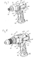
Figs. 1-3 are isometric views of differently sized impact wrench tools incorporating one or more features of the present invention. -
Fig. 4 is an isometric view of a drill tool incorporating one or more features of the present invention. -
Fig. 5 is an elevation view illustrating the inside of one half of the clam shell housing. -
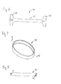
Fig. 6 is a plan view illustrating an embodiment of the reinforcing member in accordance with at least one aspect of the invention. -
Fig. 7 is an isometric view illustrating an embodiment of the reinforcing ring in accordance with at least one aspect of the invention. -
Fig. 8 is a cross-sectional view along the line 8-8 inFig. 7 . - Although the invention is illustrated and described herein with reference to specific embodiments, the invention is not intended to be limited to the details shown. Rather, various modifications may be made in the details within the scope and range of equivalents of the claims and without departing from the invention.
- Referring to
Figs. 1-4 , variousexemplary power tools 50 are illustrated. InFigs. 1-3 , the illustratedtools 50 are cordless impact wrenches and inFig. 4 , the illustratedtool 50 is a cordless drill, however, the present invention is not limited to such tools. For example, but not limited to, thetool 50 may be cordless or corded, pneumatic, or otherwise powered. Furthermore, the invention is not limited to drills and impact wrenches, but includes other power tools. Each of thefrustrated tools 50 includes atool body 52 defining ahead portion 53 and ahandle 54 depending therefrom. In each of the illustratedtools 50, aforward junction 55 and arearward junction 57 is defined at the junction between thehead portion 53 and thehandle 54. Referring toFig. 5 , an imaginary plane J extends along the junction between thehead portion 53 and thehandle 54. In each of the illustratedtools 50, atrigger 60 is provided at theforward junction 55, however, such is not required. In each of the illustratedtools 50, a. forward/reverse slide switch 62 is also provided adjacent theforward junction 55. Again, such is not required. Forward of thehead portion 53 is ahead cap 59. As illustrated inFigs. 1-4 , thehead cap 59 can have various configurations. Furthermore, as frustrated inFigs. 1-4 , thetool head 61 can also have various configurations forward thehead cap 59. - Referring to
Fig. 5 , the interior of afirst half 52A of atool housing body 52 is illustrated. In each of the illustrated embodiments, thehandle 54 defines a generallyhollow area 56 with anopening 58 into thehollow area 56. Theopening 58 is configured to receive a battery pack (not shown). As set forth above, the present invention is not limited to cordless power tools. Furthermore, while the illustrated embodiments provide thehollow area 56 and theopening 58 within thehandle 54 of theelectric tool 50, the invention is not limited to such. If ahollow area 56 is provided, it may be provided at any desired location within thetool 50 with theopening 58 correspondingly positioned to open into thehollow area 56. - In the present embodiment, a reinforcing
member 70 extends between thehead portion 53 and thehandle 54, bridging the imaginary plane J at the junction between thehead portion 53 and the handle. The reinforcingmember 70 is illustrated adjacent to theforward junction 55. The reinforcingmember 70 may also be provided additionally, or alternatively, adjacent to therearward junction 57. Referring toFig. 6 , the reinforcingmember 70 of the present embodiment has a "dog bone" configuration, i.e. anarrow middle portion 72 withwider end portions 74. Such a configuration allows themiddle portion 72 to be in tension while theends 74 are in compression. Additionally, thewider end portions 74 may provide a greater area for connection to the housing body. As such, the reinforcingmember 70 of the present embodiment is preferably positioned in high tensile regions of thetool housing 52. The reinforcingmember 70 may have other configurations, for example, a consistent width along its length for regions in which tensile load is not as great. - The reinforcing
member 70 is preferably manufactured from a metal, for example, steel, but may be manufactured from other materials having a higher tensile strength than the material of which thehousing body 52 is manufactured, for example, composite materials or reinforced plastics. The reinforcingmember 70 is preferably positioned in the mold of thehousing body 52 and over molded during molding of thehousing body 52, however, other methods may be utilized to interconnect the reinforcing member with thehousing body 52. In clam shell type housings, the reinforcingmember 70 is preferably provided in each half of the housing, but such is not required. - Referring again to
Figs. 1-4 , each of the illustratedtools 50 is of the clam shell type. That is, thehousing body 52 is made up of two opposed, interconnectedhalves halves various screw holes halves halves - Referring to
Figs. 1-4 and7-8 , a continuous reinforcingring 98 is preferably provided about thetool housing 52 to maintain thehalves ring 98 is continuous, it is less susceptible to wear or loosening. In the illustrated embodiments, thering 98 is provided adjacent to the opening 58. As illustrated inFig. 5 , thehousing 52 may be provided with acircumferential channel 96 configured to receive thering 98. As illustrated inFig. 8 , thering 98 may include aninternal channel 97 such that thering 98 is snap fit overprojections 99 extending from thehousing 52 about thechannel 96. While the reinforcingring 98 is illustrated about theopening 58, it is not limited to such position. For example, the reinforcing ring may be positioned adjacent to the junction plane J, about the forward end of thehead portion 53, the rearward end of thehead portion 53 or any other location where radial forces may make such desirable. Additionally, while a pistol style housing is illustrated, the reinforcing ring may be used with tools having other configurations, for example, a linear tool body. - The reinforcing
ring 98 is preferably manufactured from metal, but may be manufactured from other substantially rigid materials. The reinforcingring 98 is preferably formed as a continuous member and snap fit or otherwise positioned about thehousing 52. Alternatively, the reinforcingring 98 may be formed with open ends which are attached, for example, via welding, after thering 98 is positioned about thehousing 58. - Referring to
Fig. 5 another aspect of one or more embodiments of the present invention is illustrated. The screw holes 80 are positioned radially outwardly on thehead portion 53. Theholes 80 are positioned such that the center to center distance D is greater than an outer diameter of the motor housing 100 (shown in phantom). In such a configuration, the centerline H extending between theholes 80 may overlap a portion of themotor housing 100, thereby allowing the rear end of thehousing body 52 to be shortened. Furthermore, it is preferable that the rear motor vents 102 extend circumferentially and are positioned such that the centerline H passes through at least one of the vents 102. - Referring to
Figs. 1-5 , another aspect of one or more embodiments of the present invention is illustrated. The central motor vents 104 are positioned circumferentially outward relative to the motor housing centerline M such that thevents 104 are approximately tangential to the outer surface of themotor housing 100. As such, cooling flow about themotor housing 100 flows efficiently through thevents 104. - Referring to
Figs. 1-4 , an aesthetic aspect of one or more embodiments of the present invention is illustrated. In a preferred aesthetic embodiment, both thehead cap 59 and the reinforcingring 98 are both the same color which is distinct from the color of thetoot housing body 52. In a further aesthetic embodiment, thehead cap 59, the forward/reverse slide switch 62 and the reinforcingring 98 are all the same color which is distinct from the color of thetool housing body 52. In another aesthetic embodiment, thehead cap 59 and the reinforcingring 98 are both a chrome color while thetool housing body 52 is a dark contrasting color, for example, a charcoal grey. In another aesthetic embodiment, thehead cap 59, the forward/reverse slide switch 62 and the reinforcingring 98 are all a chrome color while the tool housing body. 52 is a dark contrasting color, for example, a charcoal grey. The functional aspects of the present invention described above are not intended to be limited by the aesthetic features described herein. - While preferred embodiments of the invention have been shown and described herein, it will be understood that such embodiments are provided by way of example only. Numerous variations, changes and substitutions will occur to those skilled in the art without departing from the spirit of the invention. Accordingly, it is intended that the appended claims cover all such variations as fall within the spirit and scope of the invention.
Claims (15)
- A tool housing comprising a tool housing body (52) with a motor area configured to receive a motor having a motor housing (100) with a motor centreline (M), at least one motor vent (104) provided along the tool housing body (52) circumferentially outward relative to the motor centreline (M) such that the vents (104) is approximately tangential to an outer surface of the motor housing (100).
- The tool housing of claim 1, wherein the tool housing is a pistol style tool housing, the body (52) of the tool housing having a head portion (53) and a handle portion (54) depending from the head portion (53) to define a forward and/or a rear junction (55, 57).
- The tool housing of claim 1, wherein the tool housing body (52) is of a clam shell type with two opposed body halves (52A, 52B) interconnected to define the tool housing body (52).
- The tool housing of claim 3, wherein the body halves (52A, 52B) are interconnected via screws extending though various screw holes (80, 82).
- The tool housing according to at least one of claims 1 to 4, wherein the tool housing body (52) is with a motor area configured to receive a motor having a given motor diameter, wherein the at least two body components (52A, 52B) have a pair of screw holes (80) within the motor area and the screw holes (80) are positioned such that the center to center distance (D) between the screw holes (80) is greater than the motor diameter.
- The tool housing of claim 5 wherein each body component (52A, 52B) includes a motor vent (102) positioned such that a centreline (H) between the pair of screw holes (80) extends across the vent (102).
- The tool housing of claim 6 wherein each motor vent (102) extends circumferentially.
- The tool housing according to at least one of claims 1 to 7, further comprising:at least one continuous reinforcing ring (98) positioned about the tool housing body (52) to prevent splitting between the body components (52A, 52B).
- The tool housing of claim 8 wherein the reinforcing ring (98) comprises at least one of the following features:- the reinforcing ring (98) is provided about a battery opening (58) into the tool housing body (52),- the reinforcing ring (98) is configured to be snap fit about the tool housing body (52),- the reinforcing ring (98) includes an internal channel (97) configured to receive one or more projections (99) extending from the tool housing body (52),- the reinforcing ring (98) is manufactured as a continuous member,- the reinforcing ring (98) is manufactured with open ends which are permanently joined together.
- The tool housing of claim 8 wherein the tool housing body (52) includes a head portion (53) and a handle portion (54) depending therefrom with a junction (55, 57) defined therebetween, and wherein the reinforcing ring (98) is positioned proximate to the junction (55, 57).
- The tool housing of claim 8 wherein the tool housing body (52) includes a channel (96) configured to receive the reinforcing ring (98).
- The tool housing according to at least one of claims 1 to 11, wherein the body (52) has a head portion (53) and a handle portion (54) depending therefrom with a junction (55, 57) defined therebetween; and
a reinforcing member (70) extends along an inside surface of the body (52) from the head portion (53) to the handle portion (54) such that the reinforcing member (70) bridges the junction (55, 57). - The tool housing of claim 12 wherein the body (52) includes opposed body halves (52A, 52B) and at least one reinforcing member (70) extends along the inside surface of each body half (55A,55B).
- The tool housing of claim 12 wherein the junction (55, 57) includes a forward junction area (55) and a rear junction area (57) and at least one of the reinforcing members (70) is positioned adjacent to the forward junction area (55), the rear junction area (57) or both the forward and rear function areas (55, 57).
- The tool housing of claim 14 wherein the tool housing is configured to receive a trigger (60) proximate to the forward junction area (55).
Applications Claiming Priority (2)
| Application Number | Priority Date | Filing Date | Title |
|---|---|---|---|
| US80995406P | 2006-05-31 | 2006-05-31 | |
| EP07109228A EP1862268B1 (en) | 2006-05-31 | 2007-05-30 | Structural support for piston style tool housings |
Related Parent Applications (1)
| Application Number | Title | Priority Date | Filing Date |
|---|---|---|---|
| EP07109228.2 Division | 2007-05-30 |
Publications (1)
| Publication Number | Publication Date |
|---|---|
| EP2452786A1 true EP2452786A1 (en) | 2012-05-16 |
Family
ID=38475907
Family Applications (4)
| Application Number | Title | Priority Date | Filing Date |
|---|---|---|---|
| EP12154262.5A Not-in-force EP2452788B1 (en) | 2006-05-31 | 2007-05-30 | Structural support for power tool housings |
| EP12154256.7A Not-in-force EP2452787B1 (en) | 2006-05-31 | 2007-05-30 | Structural support for power tool housings |
| EP07109228A Active EP1862268B1 (en) | 2006-05-31 | 2007-05-30 | Structural support for piston style tool housings |
| EP12154260A Withdrawn EP2452786A1 (en) | 2006-05-31 | 2007-05-30 | Structural support for power tool housings |
Family Applications Before (3)
| Application Number | Title | Priority Date | Filing Date |
|---|---|---|---|
| EP12154262.5A Not-in-force EP2452788B1 (en) | 2006-05-31 | 2007-05-30 | Structural support for power tool housings |
| EP12154256.7A Not-in-force EP2452787B1 (en) | 2006-05-31 | 2007-05-30 | Structural support for power tool housings |
| EP07109228A Active EP1862268B1 (en) | 2006-05-31 | 2007-05-30 | Structural support for piston style tool housings |
Country Status (3)
| Country | Link |
|---|---|
| US (1) | US8205684B2 (en) |
| EP (4) | EP2452788B1 (en) |
| CA (4) | CA2590879C (en) |
Families Citing this family (21)
| Publication number | Priority date | Publication date | Assignee | Title |
|---|---|---|---|---|
| US8006778B2 (en) * | 2006-06-16 | 2011-08-30 | Robert Bosch Gmbh | Handheld power tool |
| DE102006041429A1 (en) * | 2006-09-04 | 2008-03-20 | Metabowerke Gmbh | Electric hand tool |
| US7896103B2 (en) | 2008-02-04 | 2011-03-01 | Ingersoll Rand Company | Power tool housing support structures |
| US9120213B2 (en) | 2011-01-21 | 2015-09-01 | Milwaukee Electric Tool Corporation | Powered ratchet wrench |
| USD678025S1 (en) * | 2011-08-08 | 2013-03-19 | Ingersoll-Rand Company | Cordless impact tool |
| JP5725354B2 (en) * | 2011-08-19 | 2015-05-27 | 日立工機株式会社 | Electric tool |
| GB201311034D0 (en) * | 2013-06-20 | 2013-08-07 | 3M Innovative Properties Co | Valve for pressurized metered dose dispensers |
| DE102013215821A1 (en) * | 2013-08-09 | 2015-02-12 | Robert Bosch Gmbh | Hand tool with an electric motor drive as a direct drive |
| US9808928B2 (en) | 2015-05-19 | 2017-11-07 | Snap-On Incorporated | Reinforcement member for handle of tool |
| US10615670B2 (en) | 2015-06-05 | 2020-04-07 | Ingersoll-Rand Industrial U.S., Inc. | Power tool user interfaces |
| WO2016196979A1 (en) | 2015-06-05 | 2016-12-08 | Ingersoll-Rand Company | Impact tools with ring gear alignment features |
| US11491616B2 (en) | 2015-06-05 | 2022-11-08 | Ingersoll-Rand Industrial U.S., Inc. | Power tools with user-selectable operational modes |
| WO2016196899A1 (en) | 2015-06-05 | 2016-12-08 | Ingersoll-Rand Company | Power tool housings |
| WO2018160748A1 (en) | 2017-02-28 | 2018-09-07 | Milwaukee Electric Tool Corporation | Powered ratchet wrench with reversing mechanism |
| US11413731B2 (en) | 2019-06-12 | 2022-08-16 | Milwaukee Electric Tool Corporation | Powered ratchet wrench |
| US11865679B2 (en) | 2019-10-11 | 2024-01-09 | Ingersoll-Rand Industrial U.S., Inc. | Battery powered impact wrench |
| JP2021137907A (en) * | 2020-03-04 | 2021-09-16 | 株式会社マキタ | Electric work machine |
| US11691261B2 (en) | 2020-06-02 | 2023-07-04 | Snap-On Incorporated | Housing clamp for a power tool |
| USD1014213S1 (en) * | 2021-05-21 | 2024-02-13 | Bosch Power Tools (China) Co., Ltd. | Power hammer |
| USD1027594S1 (en) * | 2022-01-20 | 2024-05-21 | Kurtis Mitthun | Drill |
| EP4410489A1 (en) | 2022-11-21 | 2024-08-07 | Milwaukee Electric Tool Corporation | Power tool with integrated gear case |
Citations (8)
| Publication number | Priority date | Publication date | Assignee | Title |
|---|---|---|---|---|
| DE4204947A1 (en) * | 1992-02-19 | 1993-08-26 | Scintilla Ag | POWERED HAND MACHINE |
| EP0698449A2 (en) * | 1994-07-26 | 1996-02-28 | Black & Decker Inc. | Power tool with modular drive system and method of assembly of modular drive system |
| DE19805577A1 (en) * | 1997-02-27 | 1998-09-03 | Bosch Gmbh Robert | Electric hand machine tool |
| EP1099517A2 (en) * | 1999-11-11 | 2001-05-16 | Black & Decker Inc. | Motor/handle housing and gear case mounting for portable power tool |
| EP1132178A1 (en) * | 2000-03-10 | 2001-09-12 | Black & Decker Inc. | Power tool |
| US20030094293A1 (en) * | 2001-11-16 | 2003-05-22 | Rudolf Fuchs | Hand power tool with housing having air inlet and air outlet openings |
| WO2005039829A1 (en) * | 2003-09-29 | 2005-05-06 | Robert Bosch Gmbh | Battery-driven screwdriver |
| US20060037766A1 (en) * | 1999-04-29 | 2006-02-23 | Gass Stephen F | Power tools |
Family Cites Families (35)
| Publication number | Priority date | Publication date | Assignee | Title |
|---|---|---|---|---|
| US3413498A (en) * | 1965-08-09 | 1968-11-26 | Rockwell Mfg Co | Electrically powered hand tool |
| DE2042012A1 (en) * | 1970-08-25 | 1972-03-02 | Bosch Gmbh Robert | Power tool |
| US3908139A (en) * | 1974-06-10 | 1975-09-23 | Singer Co | Portable power tools |
| US4081704A (en) * | 1976-02-13 | 1978-03-28 | Skil Corporation | Powered hand-held tool with unitary sub-assembly mounted by the tool housing sections |
| PL114843B1 (en) * | 1976-08-13 | 1981-02-28 | Gewerk Eisenhuette Westfalia | Coupling member for segments of trough-shaped running track of a chain driven scraper coveyor |
| US4133971A (en) * | 1977-02-09 | 1979-01-09 | The Hoover Company | Hand grip mounted switch and strain relief |
| US4144738A (en) * | 1977-10-11 | 1979-03-20 | Scovill Manufacturing Company | Fastener setting hand tool |
| NO152611C (en) * | 1978-10-16 | 1985-10-23 | Plg Res | PLASTIC NETWORK CONSTRUCTION, PROCEDURE FOR ITS MANUFACTURING AND USE OF THE CONSTRUCTION |
| DE8505814U1 (en) * | 1985-03-01 | 1985-05-30 | Proxxon GmbH, 5561 Niersbach | ELECTRIC TOOL |
| DE4015449A1 (en) * | 1990-05-14 | 1991-11-21 | Hilti Ag | POWDER POWERED SETTING DEVICE |
| DE4226903A1 (en) * | 1992-08-14 | 1994-02-17 | Bosch Gmbh Robert | Hand tool |
| US5372420A (en) * | 1993-03-11 | 1994-12-13 | Black & Decker Inc. | Device having rotatable head |
| JPH0825249A (en) * | 1994-07-12 | 1996-01-30 | Makita Corp | Vibrating tool and vibration isolating ring |
| US5531538A (en) * | 1994-10-13 | 1996-07-02 | Ryobi North America | Portable electric power tool housing |
| US6318216B1 (en) * | 1997-05-07 | 2001-11-20 | Snap-On Technologies, Inc. | Composite box wrench with reinforcing and retaining structure |
| US6012622A (en) * | 1998-04-20 | 2000-01-11 | Illinois Tool Works Inc. | Fastener driving tool for trim applications |
| US6345927B1 (en) * | 2000-03-08 | 2002-02-12 | General Electric Company | Weld reinforcement |
| US6568483B2 (en) * | 2001-02-07 | 2003-05-27 | Ingersoll-Rand Company | Interchangeable pistol grip handles for pneumatic tools and seals therefor |
| DE50209495D1 (en) * | 2001-04-11 | 2007-03-29 | Bosch Gmbh Robert | HAND TOOL MACHINE WITH VIBRATION STEAMED HANDLE |
| US7024966B2 (en) * | 2001-07-20 | 2006-04-11 | Mobiletron Electronics Co., Ltd. | Positionable power screwdriver |
| US6729414B2 (en) * | 2002-07-16 | 2004-05-04 | Black & Decker Inc. | Cordless drill with metal housing |
| DE10255162A1 (en) * | 2002-11-22 | 2004-06-03 | Hilti Ag | Vibration-decoupled hammer mechanism assembly |
| US20040188119A1 (en) * | 2003-03-24 | 2004-09-30 | Hsin-Chu Chen | Portable electric-powered tool |
| DE10345133A1 (en) * | 2003-09-29 | 2005-04-21 | Bosch Gmbh Robert | Cordless drill/driver, comprising permanently installed battery and inner surface of housing serving as sun wheel |
| JP4084319B2 (en) * | 2004-02-23 | 2008-04-30 | リョービ株式会社 | Electric tool |
| DE102004051913A1 (en) | 2004-08-09 | 2006-02-23 | Robert Bosch Gmbh | Cordless Screwdriver |
| DE102004041219A1 (en) * | 2004-08-26 | 2006-03-02 | Robert Bosch Gmbh | Hand machine tool grip device with a vibration shielding unit |
| US7252156B2 (en) * | 2005-03-31 | 2007-08-07 | Makita Corporation | Vibration isolation handle |
| DE102005038088A1 (en) * | 2005-08-11 | 2007-02-15 | Hilti Ag | Connecting arrangement between main housing and handle housing |
| GB2431610A (en) * | 2006-03-03 | 2007-05-02 | Black & Decker Inc | Handle Damping System |
| DE102006027784A1 (en) * | 2006-06-16 | 2007-12-20 | Robert Bosch Gmbh | Hand tool machine e.g. angle grinder, has damping unit connected between two housing parts arranged at distance from each other in longitudinal direction of machine |
| US8006778B2 (en) * | 2006-06-16 | 2011-08-30 | Robert Bosch Gmbh | Handheld power tool |
| DE102006029630A1 (en) * | 2006-06-28 | 2008-01-03 | Robert Bosch Gmbh | Hand tool |
| JP4756473B2 (en) * | 2006-07-20 | 2011-08-24 | 日立工機株式会社 | Electric tool |
| DE102007055843A1 (en) * | 2007-12-17 | 2009-06-25 | Hilti Aktiengesellschaft | Hand tool with vibration compensator |
-
2007
- 2007-05-30 CA CA2590879A patent/CA2590879C/en not_active Expired - Fee Related
- 2007-05-30 CA CA2873135A patent/CA2873135A1/en not_active Abandoned
- 2007-05-30 EP EP12154262.5A patent/EP2452788B1/en not_active Not-in-force
- 2007-05-30 US US11/755,260 patent/US8205684B2/en active Active
- 2007-05-30 CA CA2873139A patent/CA2873139A1/en not_active Abandoned
- 2007-05-30 EP EP12154256.7A patent/EP2452787B1/en not_active Not-in-force
- 2007-05-30 EP EP07109228A patent/EP1862268B1/en active Active
- 2007-05-30 EP EP12154260A patent/EP2452786A1/en not_active Withdrawn
- 2007-05-30 CA CA2873137A patent/CA2873137A1/en not_active Abandoned
Patent Citations (8)
| Publication number | Priority date | Publication date | Assignee | Title |
|---|---|---|---|---|
| DE4204947A1 (en) * | 1992-02-19 | 1993-08-26 | Scintilla Ag | POWERED HAND MACHINE |
| EP0698449A2 (en) * | 1994-07-26 | 1996-02-28 | Black & Decker Inc. | Power tool with modular drive system and method of assembly of modular drive system |
| DE19805577A1 (en) * | 1997-02-27 | 1998-09-03 | Bosch Gmbh Robert | Electric hand machine tool |
| US20060037766A1 (en) * | 1999-04-29 | 2006-02-23 | Gass Stephen F | Power tools |
| EP1099517A2 (en) * | 1999-11-11 | 2001-05-16 | Black & Decker Inc. | Motor/handle housing and gear case mounting for portable power tool |
| EP1132178A1 (en) * | 2000-03-10 | 2001-09-12 | Black & Decker Inc. | Power tool |
| US20030094293A1 (en) * | 2001-11-16 | 2003-05-22 | Rudolf Fuchs | Hand power tool with housing having air inlet and air outlet openings |
| WO2005039829A1 (en) * | 2003-09-29 | 2005-05-06 | Robert Bosch Gmbh | Battery-driven screwdriver |
Also Published As
| Publication number | Publication date |
|---|---|
| EP1862268A2 (en) | 2007-12-05 |
| EP2452787A2 (en) | 2012-05-16 |
| US8205684B2 (en) | 2012-06-26 |
| EP2452788B1 (en) | 2013-07-24 |
| CA2590879C (en) | 2015-02-17 |
| EP2452787B1 (en) | 2014-07-02 |
| CA2873135A1 (en) | 2007-11-30 |
| CA2590879A1 (en) | 2007-11-30 |
| CA2873139A1 (en) | 2007-11-30 |
| EP2452788A1 (en) | 2012-05-16 |
| US20080000665A1 (en) | 2008-01-03 |
| EP1862268B1 (en) | 2012-05-02 |
| EP2452787A3 (en) | 2012-08-08 |
| EP1862268A3 (en) | 2009-04-08 |
| CA2873137A1 (en) | 2007-11-30 |
Similar Documents
| Publication | Publication Date | Title |
|---|---|---|
| CA2590879C (en) | Structural support for power tool housings | |
| US7896103B2 (en) | Power tool housing support structures | |
| US8573322B2 (en) | Hook for electric power tools and electric power tool equipped with the hook | |
| US7845427B2 (en) | Sealing element of hand power tool housing | |
| US8667648B2 (en) | Ball handle assembly for a handheld tool | |
| US6446734B1 (en) | Motor/handle housing and gear case mounting for portable power tool | |
| US20050155778A1 (en) | Power tool having outer protection layer | |
| WO2011111465A1 (en) | Structure for prevention of falling-off of socket in motorized tool | |
| CA2943529C (en) | Aluminum striking tools | |
| US6962098B2 (en) | Undermolded structures and method of making same | |
| WO2019109279A1 (en) | Power head configured to operate multiple tool heads with universal rotary driver | |
| US10131048B2 (en) | Connection device and drive assembly for a cutting tool | |
| JP6862121B2 (en) | Long hedge trimmer | |
| US11554474B2 (en) | Mating interface for a power head configured to operate multiple tool attachments | |
| EP3455520B1 (en) | Articulated energy chain | |
| CN101412215B (en) | Handle and power tool | |
| CN109128287B (en) | Power tool | |
| TWM634916U (en) | Multifunctional pliers for bicycle | |
| CA108728S (en) | Steering handle for outboard motor |
Legal Events
| Date | Code | Title | Description |
|---|---|---|---|
| PUAI | Public reference made under article 153(3) epc to a published international application that has entered the european phase |
Free format text: ORIGINAL CODE: 0009012 |
|
| 17P | Request for examination filed |
Effective date: 20120207 |
|
| AC | Divisional application: reference to earlier application |
Ref document number: 1862268 Country of ref document: EP Kind code of ref document: P |
|
| AK | Designated contracting states |
Kind code of ref document: A1 Designated state(s): DE FR GB IT SE |
|
| RIN1 | Information on inventor provided before grant (corrected) |
Inventor name: KOKINELIS, CHRISTOPHER ANTHONY Inventor name: SEITH, WARREN ANDREW |
|
| STAA | Information on the status of an ep patent application or granted ep patent |
Free format text: STATUS: THE APPLICATION IS DEEMED TO BE WITHDRAWN |
|
| 18D | Application deemed to be withdrawn |
Effective date: 20121117 |