EP2452632A1 - Wedge knotless suture anchor - Google Patents
Wedge knotless suture anchor Download PDFInfo
- Publication number
- EP2452632A1 EP2452632A1 EP11187804A EP11187804A EP2452632A1 EP 2452632 A1 EP2452632 A1 EP 2452632A1 EP 11187804 A EP11187804 A EP 11187804A EP 11187804 A EP11187804 A EP 11187804A EP 2452632 A1 EP2452632 A1 EP 2452632A1
- Authority
- EP
- European Patent Office
- Prior art keywords
- suture
- anchor
- flexible material
- knotless
- length
- Prior art date
- Legal status (The legal status is an assumption and is not a legal conclusion. Google has not performed a legal analysis and makes no representation as to the accuracy of the status listed.)
- Granted
Links
- 239000000463 material Substances 0.000 claims description 32
- 229920000785 ultra high molecular weight polyethylene Polymers 0.000 claims description 4
- 239000004699 Ultra-high molecular weight polyethylene Substances 0.000 claims description 3
- 210000000988 bone and bone Anatomy 0.000 description 16
- 210000001519 tissue Anatomy 0.000 description 16
- 210000004872 soft tissue Anatomy 0.000 description 7
- 238000003780 insertion Methods 0.000 description 6
- 230000037431 insertion Effects 0.000 description 6
- 238000000034 method Methods 0.000 description 3
- 238000006073 displacement reaction Methods 0.000 description 2
- 239000007943 implant Substances 0.000 description 2
- 238000009434 installation Methods 0.000 description 2
- 210000003041 ligament Anatomy 0.000 description 2
- JTIGKVIOEQASGT-UHFFFAOYSA-N proquazone Chemical compound N=1C(=O)N(C(C)C)C2=CC(C)=CC=C2C=1C1=CC=CC=C1 JTIGKVIOEQASGT-UHFFFAOYSA-N 0.000 description 2
- 102000008186 Collagen Human genes 0.000 description 1
- 108010035532 Collagen Proteins 0.000 description 1
- 239000004696 Poly ether ether ketone Substances 0.000 description 1
- 229910001069 Ti alloy Inorganic materials 0.000 description 1
- RTAQQCXQSZGOHL-UHFFFAOYSA-N Titanium Chemical compound [Ti] RTAQQCXQSZGOHL-UHFFFAOYSA-N 0.000 description 1
- 229920010741 Ultra High Molecular Weight Polyethylene (UHMWPE) Polymers 0.000 description 1
- JUPQTSLXMOCDHR-UHFFFAOYSA-N benzene-1,4-diol;bis(4-fluorophenyl)methanone Chemical compound OC1=CC=C(O)C=C1.C1=CC(F)=CC=C1C(=O)C1=CC=C(F)C=C1 JUPQTSLXMOCDHR-UHFFFAOYSA-N 0.000 description 1
- 229920001436 collagen Polymers 0.000 description 1
- 239000003086 colorant Substances 0.000 description 1
- 230000006835 compression Effects 0.000 description 1
- 238000007906 compression Methods 0.000 description 1
- 230000007547 defect Effects 0.000 description 1
- 230000001419 dependent effect Effects 0.000 description 1
- 239000000835 fiber Substances 0.000 description 1
- 239000002657 fibrous material Substances 0.000 description 1
- 229910052751 metal Inorganic materials 0.000 description 1
- 239000002184 metal Substances 0.000 description 1
- 229910001092 metal group alloy Inorganic materials 0.000 description 1
- 150000002739 metals Chemical class 0.000 description 1
- 238000012986 modification Methods 0.000 description 1
- 230000004048 modification Effects 0.000 description 1
- 229920005615 natural polymer Polymers 0.000 description 1
- 229910001000 nickel titanium Inorganic materials 0.000 description 1
- HLXZNVUGXRDIFK-UHFFFAOYSA-N nickel titanium Chemical compound [Ti].[Ti].[Ti].[Ti].[Ti].[Ti].[Ti].[Ti].[Ti].[Ti].[Ti].[Ni].[Ni].[Ni].[Ni].[Ni].[Ni].[Ni].[Ni].[Ni].[Ni].[Ni].[Ni].[Ni].[Ni] HLXZNVUGXRDIFK-UHFFFAOYSA-N 0.000 description 1
- 229920006209 poly(L-lactide-co-D,L-lactide) Polymers 0.000 description 1
- 229920002530 polyetherether ketone Polymers 0.000 description 1
- 230000008439 repair process Effects 0.000 description 1
- 238000001228 spectrum Methods 0.000 description 1
- 239000010935 stainless steel Substances 0.000 description 1
- 229910001220 stainless steel Inorganic materials 0.000 description 1
- 238000006467 substitution reaction Methods 0.000 description 1
- 238000001356 surgical procedure Methods 0.000 description 1
- 239000003356 suture material Substances 0.000 description 1
- 229920001059 synthetic polymer Polymers 0.000 description 1
- 210000002435 tendon Anatomy 0.000 description 1
- 230000017423 tissue regeneration Effects 0.000 description 1
- 229910052719 titanium Inorganic materials 0.000 description 1
- 239000010936 titanium Substances 0.000 description 1
Images


Classifications
-
- A—HUMAN NECESSITIES
- A61—MEDICAL OR VETERINARY SCIENCE; HYGIENE
- A61B—DIAGNOSIS; SURGERY; IDENTIFICATION
- A61B17/00—Surgical instruments, devices or methods, e.g. tourniquets
- A61B17/04—Surgical instruments, devices or methods, e.g. tourniquets for suturing wounds; Holders or packages for needles or suture materials
- A61B17/0401—Suture anchors, buttons or pledgets, i.e. means for attaching sutures to bone, cartilage or soft tissue; Instruments for applying or removing suture anchors
- A61B2017/0403—Dowels
-
- A—HUMAN NECESSITIES
- A61—MEDICAL OR VETERINARY SCIENCE; HYGIENE
- A61B—DIAGNOSIS; SURGERY; IDENTIFICATION
- A61B17/00—Surgical instruments, devices or methods, e.g. tourniquets
- A61B17/04—Surgical instruments, devices or methods, e.g. tourniquets for suturing wounds; Holders or packages for needles or suture materials
- A61B17/0401—Suture anchors, buttons or pledgets, i.e. means for attaching sutures to bone, cartilage or soft tissue; Instruments for applying or removing suture anchors
- A61B2017/0409—Instruments for applying suture anchors
-
- A—HUMAN NECESSITIES
- A61—MEDICAL OR VETERINARY SCIENCE; HYGIENE
- A61B—DIAGNOSIS; SURGERY; IDENTIFICATION
- A61B17/00—Surgical instruments, devices or methods, e.g. tourniquets
- A61B17/04—Surgical instruments, devices or methods, e.g. tourniquets for suturing wounds; Holders or packages for needles or suture materials
- A61B17/0401—Suture anchors, buttons or pledgets, i.e. means for attaching sutures to bone, cartilage or soft tissue; Instruments for applying or removing suture anchors
- A61B2017/0412—Suture anchors, buttons or pledgets, i.e. means for attaching sutures to bone, cartilage or soft tissue; Instruments for applying or removing suture anchors having anchoring barbs or pins extending outwardly from suture anchor body
-
- A—HUMAN NECESSITIES
- A61—MEDICAL OR VETERINARY SCIENCE; HYGIENE
- A61B—DIAGNOSIS; SURGERY; IDENTIFICATION
- A61B17/00—Surgical instruments, devices or methods, e.g. tourniquets
- A61B17/04—Surgical instruments, devices or methods, e.g. tourniquets for suturing wounds; Holders or packages for needles or suture materials
- A61B17/0401—Suture anchors, buttons or pledgets, i.e. means for attaching sutures to bone, cartilage or soft tissue; Instruments for applying or removing suture anchors
- A61B2017/044—Suture anchors, buttons or pledgets, i.e. means for attaching sutures to bone, cartilage or soft tissue; Instruments for applying or removing suture anchors with a threaded shaft, e.g. screws
-
- A—HUMAN NECESSITIES
- A61—MEDICAL OR VETERINARY SCIENCE; HYGIENE
- A61B—DIAGNOSIS; SURGERY; IDENTIFICATION
- A61B17/00—Surgical instruments, devices or methods, e.g. tourniquets
- A61B17/04—Surgical instruments, devices or methods, e.g. tourniquets for suturing wounds; Holders or packages for needles or suture materials
- A61B17/0401—Suture anchors, buttons or pledgets, i.e. means for attaching sutures to bone, cartilage or soft tissue; Instruments for applying or removing suture anchors
- A61B2017/0446—Means for attaching and blocking the suture in the suture anchor
- A61B2017/0448—Additional elements on or within the anchor
- A61B2017/0451—Cams or wedges holding the suture by friction
-
- A—HUMAN NECESSITIES
- A61—MEDICAL OR VETERINARY SCIENCE; HYGIENE
- A61B—DIAGNOSIS; SURGERY; IDENTIFICATION
- A61B17/00—Surgical instruments, devices or methods, e.g. tourniquets
- A61B17/04—Surgical instruments, devices or methods, e.g. tourniquets for suturing wounds; Holders or packages for needles or suture materials
- A61B17/0401—Suture anchors, buttons or pledgets, i.e. means for attaching sutures to bone, cartilage or soft tissue; Instruments for applying or removing suture anchors
- A61B2017/0446—Means for attaching and blocking the suture in the suture anchor
- A61B2017/0461—Means for attaching and blocking the suture in the suture anchor with features cooperating with special features on the suture, e.g. protrusions on the suture
Definitions
- the present invention relates to surgical devices and, in particular, to a knotless suture anchor.
- knotless suture anchor which has a design that allows tensioning and retensioning of the anchor as necessary, while conferring great pull out strength and ease of insertion of the anchor.
- the present invention provides a knotless suture anchor for fixation of soft tissue to bone with the ability to retension the suture anchor.
- the knotless suture anchor of the present invention is a wedge knotless anchor that is suture or wire activated and that comprises an anchor body and at least two flexible strands attached to the body. At least one of the flexible strands is a tying strand (attached to tissue to be fixated) and at least another of the flexible strands is a locking strand having a first end (a wedge end) and a second end, wherein the wedge end is a larger portion with a width/diameter/cross-section greater than the width/diameter/cross-section of the second end.
- the wedge end (the larger portion) of the locking strand In the "unlocked position,” the wedge end (the larger portion) of the locking strand is outside of the anchor body and, thus, the tying strand is able to freely slide within the anchor body. In the “locked position,” the locking strand is pulled so that the wedge end (the larger portion) is pulled into the anchor body and plugs up the cannulation of the anchor body, preventing movement (sliding) of the tying tissue strand.
- FIG. 1 illustrate a side view of a suture/wire activated wedge knotless anchor according to an exemplary embodiment of the present invention (showing the tying suture looped through tissue, and the locking/wedge suture adjacent the tying suture).
- FIG. 2 illustrates a cross-sectional view of a suture/wire activated wedge knotless anchor according to another embodiment of the present invention, and in the unlocked position.
- FIG. 3 illustrates a cross-sectional view of the suture/wire activated wedge knotless anchor of FIG. 2 , in the locked position.
- FIGS. 4 and 5 illustrate subsequent steps of a method of tissue fixation with a suture/wire activated wedge knotless anchor of the present invention.
- the present invention provides surgical systems and methods for knotless ligament repair and fixation, such as fixation of soft tissue to bone.
- the suture anchor of the present invention is wedge knotless anchor that is suture/wire activated and that comprises an anchor body with at least two flexible strands extending through the body.
- at least one of the flexible strands is a tying strand (attached to tissue to be fixated) and at least another flexible strand is a locking strand having a first end (a wedge end) and a second end, wherein the wedge end is a larger portion with a width and/or diameter and/or cross-section greater than the width and/or diameter and/or cross-section of the second end.
- the flexible strands may be flexible suture strands, suture tapes, nitinol strands, or high-strength sutures such as FiberWire R suture, among many others.
- the wedge end (the larger portion) of the locking strand In the "unlocked position,” the wedge end (the larger portion) of the locking strand is outside of the anchor body and, thus, the tying strand is able to slide. In the “locked position,” the locking strand is pulled so that the wedge end (the larger portion) is pulled into the anchor body and plugs up the cannulation of the anchor body, preventing movement and/or sliding of the tying strand.
- FIGS. 1-3 illustrate exemplary wedge knotless anchors 100, 200 of the present invention.
- FIG. 1 illustrates exemplary wedge knotless anchor 100 without a post construct while
- FIGS. 2 and 3 illustrate exemplary wedge knotless anchor 200 with at least one post construct.
- Wedge knotless anchor 100 of FIG. 1 is provided with an integral body 10 (anchor or implant 10) having a proximal end 11 and a distal end 12, and two flexible strands 50, 60 extending at least partially within the anchor body 10.
- the two flexible strands 50, 60 extend about across the proximal end 11 (as shown in FIG. 1 ), i.e., about perpendicular to longitudinal axis 14a of the anchor body 10.
- he Flexible strands 50, 60 may also extend along at least a portion of longitudinal axis 14a of the body 10 (as shown in FIGS. 2 and 3 ), so that the flexible strands are moveable within lumen 14 ofthe body 10 (i.e., body 10 is configured to allow axial movement of the flexible strands with in the lumen 14).
- Proximal end 11 is provided with a drive head 13 having at least one suture eyelet 15 that allows the two Flexible strands to pass therethrough.
- Channels 15a are also formed along either side of the drive head 13 to accommodate the flexible strands, as detailed below.
- Body 10 may be provided with a plurality of ribs 19 having a truncated, conical shape, as shown in FIG. 1 .
- Body 10 may also have various configurations and geometries such as, for example, a corkscrew configuration with a thread spiraling helically around the central body and having a configuration that facilitates insertion of the suture anchor into the bone by providing a gradual change from a starting pitch (i.e, a thread disposed along the longitudinal) axis ofthe suture anchor at the distal end of the anchor) to a helical or spiral pitch around the central body 10.
- a starting pitch i.e, a thread disposed along the longitudinal
- the suture anchor 100 can be inserted more readily into the bone without the need for additional or excessive force.
- the body 10 may also have a distal end terminating in a conical, unthreaded tip terminating in a sharp point (and adjacent a threaded body), to allow easy installation of the anchor into the bone and with less tissue material displacement upon insertion.
- Flexible strand 50 shown in FIG. 1 may be a tying suture that is attached to tissue 90 (for example, looped through tissue to form a loop 51 as shown in FIG. 2 ) with free ends 50a, 50b of the tying strand 50 passing through the proximal end 11 of the anchor body (as shown in FIG. 1 ).
- Flexible strand 60 may be a locking strand with two ends: a first end 62 (not shown) with a wedge portion or wedge end 66 (that gets pulled into the eyelet 15 to fix the construct) and a second end 61 (that gets pulled to lock the tying suture 50 within the eyelet).
- the wedge end 66 is an enlarged end relative to the second end 61, i.e., the diameter/width/cross-section of the wedge end 66 is greater than the diameter/width/cross-section of the end 61.
- FIG. 1 illustrates wedge knotless anchor 100 in the "unlocked position.”
- the wedge end 66 the larger, wider, thicker portion of the locking suture 60 is located outside of the anchor body 10 and, thus, the tying strand 50 is able to freely slide within the proximal end 11 of the anchor body.
- end 61 of the locking suture 60 is pulled in the direction of arrow A of FIG. 1 , so that the wedge end 66 (the larger portion) is pulled inside the anchor body 10 and plugs up the proximal end 11 (i.e., because of its enlarged cross-section and dimension, the wedge end 66 compresses the tying suture 50 and restricts movement and sliding of the tying suture 50 within the proximal end).
- the construct By pulling on the other end 62 of the locking suture 60, the construct is released, the wedge end 66 is pulled out of the proximal end 11, the tying suture 50 is decompressed and, thus, movement of the tying suture 50 within proximal end 11 is restored.
- FIGS. 2 and 3 illustrate another exemplary embodiment of wedge knotless anchor 200 provided with an integral body 10 (anchor or implant 10) having a proximal end 11 and a distal end 12, and two flexible strands 50,60 extending at least partially within the anchor body 10.
- the two flexible strands 50, 60 extend along at least a portion of longitudinal axis 14a of the body 10, so that the flexible strands are movable within lumen 14 of the body 10.
- This embodiment allows axial movement of the flexible strands 50, 60. within the lumen 14
- proximal end 11 may be provided with a drive head to allow engagement with a driver (for example, a hand driver) for insertion of the anchor within a bone.
- a driver for example, a hand driver
- Body 10 may have various configurations and geometries such as, for example, a corkscrew configuration with a thread spiraling helically around the central body and having a configuration that facilitates insertion of the suture anchor into the bone by providing a gradual change from a Starting pitch (i.e, a thread disposed along the longitudinal axis of the suture anchor at the distal end ofthe anchor) to a helical or spiral pitch around the central body 10.
- a Starting pitch i.e, a thread disposed along the longitudinal axis of the suture anchor at the distal end ofthe anchor
- a helical or spiral pitch around the central body 10.
- the body 10 may also have a distal end terminating in a conical, unthreaded tip terminating in a sharp point (and adjacent a threaded body), to allow easy installation of the anchor into the bone and with less tissue material displacement upon insertion.
- Flexible strand 50 shown in FIGS. 2 and 3 may be a tying suture that is attached to tissue 90 (for example, looped through tissue to form a loop 51 as shown in FIG. 2 ) with free ends 50a, 50b of the tying strand 50 exiting opening 20 of the proximal end 11.
- tissue 90 for example, looped through tissue to form a loop 51 as shown in FIG. 2
- one of the free ends 50a, 50b is passed into the lumen 14 through opening 20 at the proximal end 11, and then looped around post 30 (turning post 30) located at the distal end 12, and then passed out of the lumen 14 through the opening 20 at the proximal end 11.
- Flexible strand 60 may be a locking strand with two ends: a first end 62 with a wedge portion or wedge end 66 (that gets pulled into the eyelet 15 to fix the construct) and a second end 61 (that gets pulled to lock the tying suture 50 within the eyelet).
- the wedge end 66 is an enlarged end relative to the second end 61, i.e., the diameter and/or width and/or cross-section of the wedge end 66 is greater than the diameter and/or width and/or cross-section of the end 61.
- the second end 61 of the strand 60 is passed into the lumen 14 through opening 20 at the proximal end 11, and then looped around post 30 (turning post 30) located at the distal end 12 so that the second end 61 is adjacent the suture strand 50, and then passed out of the lumen 14 through the opening 20 at the proximal end 11.
- FIG. 2 illustrates the wedge knotless anchor 200 in the "unlocked position.”
- the wedge end 66 the larger, wider, thicker portion of the locking suture 60 is located outside of the anchor body 10 and, thus, the tying strand 50 is able to freely slide around post 30 within the anchor body.
- FIG. 3 illustrates the wedge knotless anchor 200 in the "locked positions.”
- end 61 of the locking suture 60 is pulled in the direction of arrow A of FIG. 2 , so that the wedge end 66 (the larger portion) is pulled inside the anchor body 10 and plugs up the cannulation or lumen 14 (and turning post 30), preventing therefore the movement (sliding) of the tissue tying suture 50.
- the wedge end 66 is located in between the post 30 and the tying strand 50 and, as a result of the compression exercised upon the tying strand 50, the wedge end 66 is also in contact with the post 30 and the tying strand 50.
- the enlarged portion of the locking suture 60 prevents movement of the tying strand within the lumen 14 of the anchor body 10 and locks the tying strand 50.
- the construct is released, the wedge end 66 is disengaged from the post 30 and the tying suture 50 located around the post and, thus, movement of the tying suture 50 within lumen 14 is restored.
- FIGS. 1-3 illustrate only one tying suture 50, the invention also contemplates a plurality of tying sutures 50.
- FIGS. 2 and 3 illustrate anchor 200 provided with one turning post 30, the invention also contemplates anchors with more than one turning post, or similar structures. The invention also contemplates embodiments without such post(s) or similar structure(s), so that the wedge (the wedge end 66) is stuffed directly into the cannulation of the anchor body, without the aid of a post.
- Body 10 may be formed of a bioabsorbable material such as poly(l-lactide-co-d,l-lactide) 70:30 (PLDLA), PEEK, metals or metal alloys (such as stainless steel, titanium or titanium alloys, for example), absorbable and/or nonaborbable materials, natural and/or synthetic polymers, among many others.
- PLDLA poly(l-lactide-co-d,l-lactide) 70:30
- PEEK poly(l-lactide-co-d,l-lactide) 70:30
- metals or metal alloys such as stainless steel, titanium or titanium alloys, for example
- absorbable and/or nonaborbable materials natural and/or synthetic polymers, among many others.
- At least one of flexible strands 50, 60 may be a high-strength suture, such as the high strength suture sold by Arthrex, Inc. of Naples, Fla. under the registered tradename FiberWire®, which is disclosed and claimed in U.S. Pat. No. 6,716,234 .
- FiberWire® suture is formed of an advanced, high-strength fiber material, namely ultrahigh molecular weight polyethylene (UHMWPE), sold under the tradenames Spectra (Honeywell) and Dyneema (DSM), braided with at least one other fiber, natural or synthetic, to form lengths of suture material.
- UHMWPE ultrahigh molecular weight polyethylene
- DSM Dyneema
- the preferred FiberWire® suture includes a core within a hollow braided construct, the core being a twisted yarn of UHMWPE.
- the suture may optionally include filaments of various colors.
- At least one of strands 50, 60 may be also formed of suture tape (for example, a collagen stuffed suture tape) or a combination of suture and tape, a stiff material, or combination of stiff and flexible materials, depending on the intended application.
- suture tape for example, a collagen stuffed suture tape
- Wedge knotless anchors 100, 200 described above may be employed for tissue repairs, such as fixation of soft tissue to bone.
- a pilot hole 88 is created in bone 80 by employing a punch or a drill, for example.
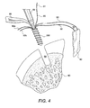
- exemplary knotless suture anchor 200 is loaded onto a driver 89 (for example, a standard hand driver), as shown in FIG. 4 .
- the knotless anchor 200 is positioned on the driver 89, and the anchor with driver is inserted into the prepared pilot hole 88 by hand.
- a mallet may be used to advance knotless anchor 200 into the hole. Once the knotless anchor 200 is advanced into the pilot hole, the driver handle is pulled straight off the anchor.
- Tensioning/retensioning of the knotless suture anchor 200 may be achieved by pulling on the free end 61 of the strand 60, to lock or unlock the tying strand 50 attached to tissue 90 (by positioning the enlarged section 66 in contact with the post 30 and the first strand 50), as necessary and as desired.
- Additional anchors may be inserted dependent upon the size of the soft tissue defect. Suture passing and knot tying are carried out in the preferred fashion to secure attachment of soft tissue to bone.
Abstract
Description
- The present invention relates to surgical devices and, in particular, to a knotless suture anchor.
- When soft tissue such as a ligament or a tendon becomes detached from a bone, surgery is usually required to reattach or reconstruct the tissue. Often, a tissue graft is attached to the bone to facilitate regrowth and permanent attachment. Techniques and devices that have been developed generally involve tying the soft tissue with suture to an anchor or a hole provided in the bone tissue. Knotless suture anchors, such as the two piece Arthrex PushLock® anchor, disclosed in
U.S. Patent No. 7,329,272 , have been developed to facilitate tissue fixation to bone. - It would be desirable to provide a knotless suture anchor which has a design that allows tensioning and retensioning of the anchor as necessary, while conferring great pull out strength and ease of insertion of the anchor.
- The present invention provides a knotless suture anchor for fixation of soft tissue to bone with the ability to retension the suture anchor.
- The knotless suture anchor of the present invention is a wedge knotless anchor that is suture or wire activated and that comprises an anchor body and at least two flexible strands attached to the body. At least one of the flexible strands is a tying strand (attached to tissue to be fixated) and at least another of the flexible strands is a locking strand having a first end (a wedge end) and a second end, wherein the wedge end is a larger portion with a width/diameter/cross-section greater than the width/diameter/cross-section of the second end.
- In the "unlocked position," the wedge end (the larger portion) of the locking strand is outside of the anchor body and, thus, the tying strand is able to freely slide within the anchor body. In the "locked position," the locking strand is pulled so that the wedge end (the larger portion) is pulled into the anchor body and plugs up the cannulation of the anchor body, preventing movement (sliding) of the tying tissue strand.
- These and other features and advantages of the invention will be more apparent from the following detailed description that is provided in connection with the accompanying drawings and illustrated exemplary embodiments ofthe invention.
-
FIG. 1 illustrate a side view of a suture/wire activated wedge knotless anchor according to an exemplary embodiment of the present invention (showing the tying suture looped through tissue, and the locking/wedge suture adjacent the tying suture). -
FIG. 2 illustrates a cross-sectional view of a suture/wire activated wedge knotless anchor according to another embodiment of the present invention, and in the unlocked position. -
FIG. 3 illustrates a cross-sectional view of the suture/wire activated wedge knotless anchor ofFIG. 2 , in the locked position. -
FIGS. 4 and5 illustrate subsequent steps of a method of tissue fixation with a suture/wire activated wedge knotless anchor of the present invention. - The present invention provides surgical systems and methods for knotless ligament repair and fixation, such as fixation of soft tissue to bone. The suture anchor of the present invention is wedge knotless anchor that is suture/wire activated and that comprises an anchor body with at least two flexible strands extending through the body. In an exemplary embodiment, at least one of the flexible strands is a tying strand (attached to tissue to be fixated) and at least another flexible strand is a locking strand having a first end (a wedge end) and a second end, wherein the wedge end is a larger portion with a width and/or diameter and/or cross-section greater than the width and/or diameter and/or cross-section of the second end. In an exemplary embodiment, the flexible strands may be flexible suture strands, suture tapes, nitinol strands, or high-strength sutures such as FiberWireⓇ suture, among many others.
- In the "unlocked position," the wedge end (the larger portion) of the locking strand is outside of the anchor body and, thus, the tying strand is able to slide. In the "locked position," the locking strand is pulled so that the wedge end (the larger portion) is pulled into the anchor body and plugs up the cannulation of the anchor body, preventing movement and/or sliding of the tying strand.
- Referring now to the drawings, where like elements are designated by like reference numerals,
FIGS. 1-3 illustrate exemplary wedgeknotless anchors FIG. 1 illustrates exemplary wedgeknotless anchor 100 without a post construct whileFIGS. 2 and3 illustrate exemplary wedgeknotless anchor 200 with at least one post construct. - Wedge
knotless anchor 100 ofFIG. 1 is provided with an integral body 10 (anchor or implant 10) having aproximal end 11 and adistal end 12, and twoflexible strands anchor body 10. In an exemplary embodiment, the twoflexible strands FIG. 1 ), i.e., about perpendicular tolongitudinal axis 14a of theanchor body 10. As described in more detail below, and with reference to another exemplary embodiment, heFlexible strands longitudinal axis 14a of the body 10 (as shown inFIGS. 2 and3 ), so that the flexible strands are moveable withinlumen 14 ofthe body 10 (i.e.,body 10 is configured to allow axial movement of the flexible strands with in the lumen 14). -
Proximal end 11 is provided with adrive head 13 having at least onesuture eyelet 15 that allows the two Flexible strands to pass therethrough. Channels 15a are also formed along either side of thedrive head 13 to accommodate the flexible strands, as detailed below. -
Body 10 may be provided with a plurality ofribs 19 having a truncated, conical shape, as shown inFIG. 1 .Body 10 may also have various configurations and geometries such as, for example, a corkscrew configuration with a thread spiraling helically around the central body and having a configuration that facilitates insertion of the suture anchor into the bone by providing a gradual change from a starting pitch (i.e, a thread disposed along the longitudinal) axis ofthe suture anchor at the distal end of the anchor) to a helical or spiral pitch around thecentral body 10. By providing the starting pitch at the distal end of the suture anchor, thesuture anchor 100 can be inserted more readily into the bone without the need for additional or excessive force. - The
body 10 may also have a distal end terminating in a conical, unthreaded tip terminating in a sharp point (and adjacent a threaded body), to allow easy installation of the anchor into the bone and with less tissue material displacement upon insertion. -
Flexible strand 50 shown inFIG. 1 may be a tying suture that is attached to tissue 90 (for example, looped through tissue to form aloop 51 as shown inFIG. 2 ) withfree ends tying strand 50 passing through theproximal end 11 of the anchor body (as shown inFIG. 1 ).Flexible strand 60 may be a locking strand with two ends: a first end 62 (not shown) with a wedge portion or wedge end 66 (that gets pulled into theeyelet 15 to fix the construct) and a second end 61 (that gets pulled to lock thetying suture 50 within the eyelet). Thewedge end 66 is an enlarged end relative to thesecond end 61, i.e., the diameter/width/cross-section of thewedge end 66 is greater than the diameter/width/cross-section of theend 61. -
FIG. 1 illustrates wedgeknotless anchor 100 in the "unlocked position." In this position, the wedge end 66 (the larger, wider, thicker portion) of thelocking suture 60 is located outside of theanchor body 10 and, thus, thetying strand 50 is able to freely slide within theproximal end 11 of the anchor body. - In the "locked position,"
end 61 of thelocking suture 60 is pulled in the direction of arrow A ofFIG. 1 , so that the wedge end 66 (the larger portion) is pulled inside theanchor body 10 and plugs up the proximal end 11 (i.e., because of its enlarged cross-section and dimension, thewedge end 66 compresses thetying suture 50 and restricts movement and sliding of thetying suture 50 within the proximal end). - By pulling on the
other end 62 of thelocking suture 60, the construct is released, thewedge end 66 is pulled out of theproximal end 11, thetying suture 50 is decompressed and, thus, movement of thetying suture 50 withinproximal end 11 is restored. -
FIGS. 2 and3 illustrate another exemplary embodiment of wedgeknotless anchor 200 provided with an integral body 10 (anchor or implant 10) having aproximal end 11 and adistal end 12, and twoflexible strands anchor body 10. In this exemplary-only embodiment, the twoflexible strands longitudinal axis 14a of thebody 10, so that the flexible strands are movable withinlumen 14 of thebody 10. This embodiment allows axial movement of theflexible strands lumen 14 - As in the previous embodiment,
proximal end 11 may be provided with a drive head to allow engagement with a driver (for example, a hand driver) for insertion of the anchor within a bone. -
Body 10 may have various configurations and geometries such as, for example, a corkscrew configuration with a thread spiraling helically around the central body and having a configuration that facilitates insertion of the suture anchor into the bone by providing a gradual change from a Starting pitch (i.e, a thread disposed along the longitudinal axis of the suture anchor at the distal end ofthe anchor) to a helical or spiral pitch around thecentral body 10. By providing the starting pitch at the distal end of the suture anchor, thesuture anchor 100 can be inserted more readily into the bone without the need for additional or excessive force. - The
body 10 may also have a distal end terminating in a conical, unthreaded tip terminating in a sharp point (and adjacent a threaded body), to allow easy installation of the anchor into the bone and with less tissue material displacement upon insertion. -
Flexible strand 50 shown inFIGS. 2 and3 may be a tying suture that is attached to tissue 90 (for example, looped through tissue to form aloop 51 as shown inFIG. 2 ) withfree ends tying strand 50 exiting opening 20 of theproximal end 11. In use, one of thefree ends lumen 14 through opening 20 at theproximal end 11, and then looped around post 30 (turning post 30) located at thedistal end 12, and then passed out of thelumen 14 through the opening 20 at theproximal end 11. -
Flexible strand 60 may be a locking strand with two ends: afirst end 62 with a wedge portion or wedge end 66 (that gets pulled into theeyelet 15 to fix the construct) and a second end 61 (that gets pulled to lock thetying suture 50 within the eyelet). Thewedge end 66 is an enlarged end relative to thesecond end 61, i.e., the diameter and/or width and/or cross-section of thewedge end 66 is greater than the diameter and/or width and/or cross-section of theend 61. In use, thesecond end 61 of thestrand 60 is passed into thelumen 14 through opening 20 at theproximal end 11, and then looped around post 30 (turning post 30) located at thedistal end 12 so that thesecond end 61 is adjacent thesuture strand 50, and then passed out of thelumen 14 through the opening 20 at theproximal end 11. -
FIG. 2 illustrates the wedgeknotless anchor 200 in the "unlocked position." In this position, the wedge end 66 (the larger, wider, thicker portion) of thelocking suture 60 is located outside of theanchor body 10 and, thus, thetying strand 50 is able to freely slide aroundpost 30 within the anchor body. -
FIG. 3 illustrates the wedgeknotless anchor 200 in the "locked positions." In this position,end 61 of thelocking suture 60 is pulled in the direction of arrow A ofFIG. 2 , so that the wedge end 66 (the larger portion) is pulled inside theanchor body 10 and plugs up the cannulation or lumen 14 (and turning post 30), preventing therefore the movement (sliding) of thetissue tying suture 50. In the "locked position" or "locked configuration" shown inFIG. 3 , thewedge end 66 is located in between thepost 30 and thetying strand 50 and, as a result of the compression exercised upon thetying strand 50, thewedge end 66 is also in contact with thepost 30 and thetying strand 50. In this manner, the enlarged portion of thelocking suture 60 prevents movement of the tying strand within thelumen 14 of theanchor body 10 and locks thetying strand 50. By pulling on theother end 62 of thelocking suture 60, the construct is released, thewedge end 66 is disengaged from thepost 30 and thetying suture 50 located around the post and, thus, movement of thetying suture 50 withinlumen 14 is restored. - Although
FIGS. 1-3 illustrate only one tyingsuture 50, the invention also contemplates a plurality of tyingsutures 50. AlthoughFIGS. 2 and3 illustrateanchor 200 provided with one turningpost 30, the invention also contemplates anchors with more than one turning post, or similar structures. The invention also contemplates embodiments without such post(s) or similar structure(s), so that the wedge (the wedge end 66) is stuffed directly into the cannulation of the anchor body, without the aid of a post. -
Body 10 may be formed of a bioabsorbable material such as poly(l-lactide-co-d,l-lactide) 70:30 (PLDLA), PEEK, metals or metal alloys (such as stainless steel, titanium or titanium alloys, for example), absorbable and/or nonaborbable materials, natural and/or synthetic polymers, among many others. Althoughbody 10 ofanchor 100 has been illustrated as having a ribbed configuration, the invention is not limited to this exemplary only embodiment and contemplates an anchor having different shapes and geometries, or a combination of different shapes and geometries. - At least one of
flexible strands U.S. Pat. No. 6,716,234 . FiberWire® suture is formed of an advanced, high-strength fiber material, namely ultrahigh molecular weight polyethylene (UHMWPE), sold under the tradenames Spectra (Honeywell) and Dyneema (DSM), braided with at least one other fiber, natural or synthetic, to form lengths of suture material. The preferred FiberWire® suture includes a core within a hollow braided construct, the core being a twisted yarn of UHMWPE. The suture may optionally include filaments of various colors. - At least one of
strands - Wedge knotless anchors 100, 200 described above may be employed for tissue repairs, such as fixation of soft tissue to bone. In an exemplary embodiment only, and with reference to
FIGS. 4 and5 , apilot hole 88 is created inbone 80 by employing a punch or a drill, for example. After thepilot hole 88 is created and the punch or drill is removed, exemplaryknotless suture anchor 200 is loaded onto a driver 89 (for example, a standard hand driver), as shown inFIG. 4 . Theknotless anchor 200 is positioned on thedriver 89, and the anchor with driver is inserted into theprepared pilot hole 88 by hand. A mallet may be used to advanceknotless anchor 200 into the hole. Once theknotless anchor 200 is advanced into the pilot hole, the driver handle is pulled straight off the anchor. - Tensioning/retensioning of the
knotless suture anchor 200 may be achieved by pulling on thefree end 61 of thestrand 60, to lock or unlock the tyingstrand 50 attached to tissue 90 (by positioning theenlarged section 66 in contact with thepost 30 and the first strand 50), as necessary and as desired. - Additional anchors may be inserted dependent upon the size of the soft tissue defect. Suture passing and knot tying are carried out in the preferred fashion to secure attachment of soft tissue to bone.
- While the present invention is described herein with reference to illustrative embodiments for particular applications, it should be understood that the invention is not limited thereto. Those having ordinary skill in the art and access to the teachings provided herein will recognize additional modifications, applications, embodiments and substitution of equivalents all fall within the scope of the invention. Accordingly, the invention is not to be considered as limited by the foregoing description.
Claims (12)
- A knotless anchor for fixation of a length of a flexible material, comprising:an anchor body having a proximal end and a distal end, and a cannulation extending from an opening at the proximal end and within the anchor body;a first flexible material disposed at least partially within the anchor body,
the first flexible material being attached to tissue to be fixated; anda second flexible material disposed at least partially within the anchor body and adjacent the first flexible material, the second flexible material being configured to compress the first flexible material against at least the anchor body and restrict movement of the first flexible material within the anchor body. - The knotless anchor of claim 1, wherein the second flexible material has a first portion with a first cross-section and a second portion with a second-cross section, the first cross-section being different from the second cross-section.
- The knotless anchor of claim 1, wherein the second flexible material has a first portion with a first width and a second portion with a second width, the first width being different from the second width.
- The knotless anchor of claim 1, wherein the second flexible material has a first portion with a first diameter and a second portion with a second diameter, the first diameter being different from the second diameter.
- The knotless anchor of claim 1, wherein the first and second flexible materials extend at least along a longitudinal portion of the anchor body.
- The knotless anchor of claim 1, wherein the first and second flexible materials extend at least across the proximal end of the body.
- The knotless anchor of claim 1, wherein at least one of the first and second flexible materials is a suture strand, a suture tape, a UHMWPE suture or a combination of suture strand, suture tape, or UHMWPE suture.
- The knotless anchor of claim 1, wherein the first flexible material is passed through the opening at the proximal end and into the cannulationofthe anchor body, looped around at least one post located at the distal end, and then passed out of the cannulation of the anchor body and through the opening at the proximal end.
- A knotless suture anchor for fixation of a length of suture, comprising:an anchor body having a proximal end, a distal end, a lumen opening at the proximal end, and at least one turning post extending within the anchor body and across the lumen at the distal end, to allow a length of suture to be passed into the lumen, from the proximal end, looped around the at least one turning post at the distal end, and passed out of the lumen through the proximal end; anda flexible material disposed at least partially within the anchor body and
adjacent the length of suture, the flexible material being located between the turning post and the length of suture, the flexible material being moveable within the lumen and configured to allow axial movement of the length of suture within the lumen when the flexible material is in a first position, and to prevent axial movement of the length of suture within the body when the flexible material is in a second position. - The knotless suture anchor of claim 9, wherein the flexible material has a first longitudinal portion which has a first cross-section and a second longitudinal portion which has a second cross-section which is larger than the first cross-section, and wherein when the flexible material is in the second position, the second longitudinal portion of the flexible material presses the length of suture against the body and limits movement of the length of suture, and, when the flexible material is in the first position, the second longitudinal portion of the flexible material does not press the length of suture against the body and does not limit movement of the length of suture within the lumen.
- The knotless suture anchor of claim 9, wherein the at least one turning post is a rod disposed transversally within a portion of the body and distal to the lumen opening.
- The knotless suture anchor of claim 9, wherein the flexible material is a suture strand or a suture tape, or combination of suture strand and suture tape.
Applications Claiming Priority (1)
| Application Number | Priority Date | Filing Date | Title |
|---|---|---|---|
| US41244210P | 2010-11-11 | 2010-11-11 |
Publications (2)
| Publication Number | Publication Date |
|---|---|
| EP2452632A1 true EP2452632A1 (en) | 2012-05-16 |
| EP2452632B1 EP2452632B1 (en) | 2016-05-11 |
Family
ID=44905671
Family Applications (1)
| Application Number | Title | Priority Date | Filing Date |
|---|---|---|---|
| EP11187804.7A Active EP2452632B1 (en) | 2010-11-11 | 2011-11-04 | Wedge knotless suture anchor |
Country Status (2)
| Country | Link |
|---|---|
| US (1) | US8986346B2 (en) |
| EP (1) | EP2452632B1 (en) |
Families Citing this family (80)
| Publication number | Priority date | Publication date | Assignee | Title |
|---|---|---|---|---|
| EP2314257B9 (en) | 2000-05-01 | 2013-02-27 | ArthroSurface, Inc. | System for joint resurface repair |
| US6610067B2 (en) | 2000-05-01 | 2003-08-26 | Arthrosurface, Incorporated | System and method for joint resurface repair |
| US8388624B2 (en) | 2003-02-24 | 2013-03-05 | Arthrosurface Incorporated | Trochlear resurfacing system and method |
| WO2006004885A2 (en) | 2004-06-28 | 2006-01-12 | Arthrosurface, Inc. | System for articular surface replacement |
| US9801708B2 (en) | 2004-11-05 | 2017-10-31 | Biomet Sports Medicine, Llc | Method and apparatus for coupling soft tissue to a bone |
| US7905904B2 (en) | 2006-02-03 | 2011-03-15 | Biomet Sports Medicine, Llc | Soft tissue repair device and associated methods |
| US7749250B2 (en) | 2006-02-03 | 2010-07-06 | Biomet Sports Medicine, Llc | Soft tissue repair assembly and associated method |
| US9017381B2 (en) | 2007-04-10 | 2015-04-28 | Biomet Sports Medicine, Llc | Adjustable knotless loops |
| US8303604B2 (en) | 2004-11-05 | 2012-11-06 | Biomet Sports Medicine, Llc | Soft tissue repair device and method |
| US7601165B2 (en) | 2006-09-29 | 2009-10-13 | Biomet Sports Medicine, Llc | Method and apparatus for forming a self-locking adjustable suture loop |
| US8298262B2 (en) | 2006-02-03 | 2012-10-30 | Biomet Sports Medicine, Llc | Method for tissue fixation |
| US8137382B2 (en) | 2004-11-05 | 2012-03-20 | Biomet Sports Medicine, Llc | Method and apparatus for coupling anatomical features |
| US8088130B2 (en) | 2006-02-03 | 2012-01-03 | Biomet Sports Medicine, Llc | Method and apparatus for coupling soft tissue to a bone |
| US8118836B2 (en) | 2004-11-05 | 2012-02-21 | Biomet Sports Medicine, Llc | Method and apparatus for coupling soft tissue to a bone |
| US8128658B2 (en) | 2004-11-05 | 2012-03-06 | Biomet Sports Medicine, Llc | Method and apparatus for coupling soft tissue to bone |
| US7909851B2 (en) | 2006-02-03 | 2011-03-22 | Biomet Sports Medicine, Llc | Soft tissue repair device and associated methods |
| US8361113B2 (en) | 2006-02-03 | 2013-01-29 | Biomet Sports Medicine, Llc | Method and apparatus for coupling soft tissue to a bone |
| US10517587B2 (en) | 2006-02-03 | 2019-12-31 | Biomet Sports Medicine, Llc | Method and apparatus for forming a self-locking adjustable loop |
| US8801783B2 (en) | 2006-09-29 | 2014-08-12 | Biomet Sports Medicine, Llc | Prosthetic ligament system for knee joint |
| US9408599B2 (en) | 2006-02-03 | 2016-08-09 | Biomet Sports Medicine, Llc | Method and apparatus for coupling soft tissue to a bone |
| US8562647B2 (en) | 2006-09-29 | 2013-10-22 | Biomet Sports Medicine, Llc | Method and apparatus for securing soft tissue to bone |
| US8652171B2 (en) | 2006-02-03 | 2014-02-18 | Biomet Sports Medicine, Llc | Method and apparatus for soft tissue fixation |
| US9078644B2 (en) | 2006-09-29 | 2015-07-14 | Biomet Sports Medicine, Llc | Fracture fixation device |
| US9468433B2 (en) | 2006-02-03 | 2016-10-18 | Biomet Sports Medicine, Llc | Method and apparatus for forming a self-locking adjustable loop |
| US9538998B2 (en) | 2006-02-03 | 2017-01-10 | Biomet Sports Medicine, Llc | Method and apparatus for fracture fixation |
| US8968364B2 (en) | 2006-02-03 | 2015-03-03 | Biomet Sports Medicine, Llc | Method and apparatus for fixation of an ACL graft |
| US8652172B2 (en) | 2006-02-03 | 2014-02-18 | Biomet Sports Medicine, Llc | Flexible anchors for tissue fixation |
| US11311287B2 (en) | 2006-02-03 | 2022-04-26 | Biomet Sports Medicine, Llc | Method for tissue fixation |
| US8597327B2 (en) | 2006-02-03 | 2013-12-03 | Biomet Manufacturing, Llc | Method and apparatus for sternal closure |
| US8562645B2 (en) | 2006-09-29 | 2013-10-22 | Biomet Sports Medicine, Llc | Method and apparatus for forming a self-locking adjustable loop |
| US11259792B2 (en) | 2006-02-03 | 2022-03-01 | Biomet Sports Medicine, Llc | Method and apparatus for coupling anatomical features |
| US9149267B2 (en) | 2006-02-03 | 2015-10-06 | Biomet Sports Medicine, Llc | Method and apparatus for coupling soft tissue to a bone |
| US8500818B2 (en) | 2006-09-29 | 2013-08-06 | Biomet Manufacturing, Llc | Knee prosthesis assembly with ligament link |
| US11259794B2 (en) | 2006-09-29 | 2022-03-01 | Biomet Sports Medicine, Llc | Method for implanting soft tissue |
| US9918826B2 (en) | 2006-09-29 | 2018-03-20 | Biomet Sports Medicine, Llc | Scaffold for spring ligament repair |
| US8672969B2 (en) | 2006-09-29 | 2014-03-18 | Biomet Sports Medicine, Llc | Fracture fixation device |
| US9358029B2 (en) | 2006-12-11 | 2016-06-07 | Arthrosurface Incorporated | Retrograde resection apparatus and method |
| US10945743B2 (en) | 2009-04-17 | 2021-03-16 | Arthrosurface Incorporated | Glenoid repair system and methods of use thereof |
| WO2010121246A1 (en) | 2009-04-17 | 2010-10-21 | Arthrosurface Incorporated | Glenoid resurfacing system and method |
| WO2010121250A1 (en) | 2009-04-17 | 2010-10-21 | Arthrosurface Incorporated | Glenoid resurfacing system and method |
| CA2792048A1 (en) | 2010-03-05 | 2011-09-09 | Arthrosurface Incorporated | Tibial resurfacing system and method |
| US8808326B2 (en) | 2010-11-24 | 2014-08-19 | Arthrocare Corporation | Suture |
| US20120158051A1 (en) * | 2010-12-17 | 2012-06-21 | Foerster Seth A | Re-tensionable knotless suture system |
| US9066716B2 (en) | 2011-03-30 | 2015-06-30 | Arthrosurface Incorporated | Suture coil and suture sheath for tissue repair |
| US9107653B2 (en) * | 2011-09-22 | 2015-08-18 | Arthrex, Inc. | Tensionable knotless anchors with splice and methods of tissue repair |
| US9357991B2 (en) | 2011-11-03 | 2016-06-07 | Biomet Sports Medicine, Llc | Method and apparatus for stitching tendons |
| US9381013B2 (en) | 2011-11-10 | 2016-07-05 | Biomet Sports Medicine, Llc | Method for coupling soft tissue to a bone |
| US9357992B2 (en) | 2011-11-10 | 2016-06-07 | Biomet Sports Medicine, Llc | Method for coupling soft tissue to a bone |
| US20130165982A1 (en) | 2011-12-22 | 2013-06-27 | Arthrosurface Incorporated | System and Method for Bone Fixation |
| WO2014008126A1 (en) | 2012-07-03 | 2014-01-09 | Arthrosurface Incorporated | System and method for joint resurfacing and repair |
| KR20150129700A (en) * | 2013-03-06 | 2015-11-20 | 스미스 앤드 네퓨, 인크. | Microanchor |
| US9757119B2 (en) | 2013-03-08 | 2017-09-12 | Biomet Sports Medicine, Llc | Visual aid for identifying suture limbs arthroscopically |
| US9918827B2 (en) | 2013-03-14 | 2018-03-20 | Biomet Sports Medicine, Llc | Scaffold for spring ligament repair |
| US9492200B2 (en) | 2013-04-16 | 2016-11-15 | Arthrosurface Incorporated | Suture system and method |
| US20150250472A1 (en) | 2014-03-07 | 2015-09-10 | Arthrosurface Incorporated | Delivery System for Articular Surface Implant |
| US10624748B2 (en) | 2014-03-07 | 2020-04-21 | Arthrosurface Incorporated | System and method for repairing articular surfaces |
| US11607319B2 (en) | 2014-03-07 | 2023-03-21 | Arthrosurface Incorporated | System and method for repairing articular surfaces |
| USD740419S1 (en) * | 2014-08-08 | 2015-10-06 | Dunamis, LLC | Suture anchor |
| USD740418S1 (en) * | 2014-08-08 | 2015-10-06 | Dunamis, LLC | Suture anchor |
| US10582957B2 (en) * | 2014-09-19 | 2020-03-10 | Crossroads Extremity Systems, Llc | Bone fixation implant and means of fixation |
| US10820918B2 (en) | 2015-07-17 | 2020-11-03 | Crossroads Extremity Systems, Llc | Transosseous guide and method |
| US9962174B2 (en) | 2015-07-17 | 2018-05-08 | Kator, Llc | Transosseous method |
| US10258401B2 (en) | 2015-07-17 | 2019-04-16 | Kator, Llc | Transosseous guide |
| US10226243B2 (en) | 2015-08-04 | 2019-03-12 | Kator, Llc | Transosseous suture anchor |
| US10335136B2 (en) | 2015-08-20 | 2019-07-02 | Arthrex, Inc. | Tensionable constructs with multi-limb locking mechanism through single splice and methods of tissue repair |
| US10265060B2 (en) | 2015-08-20 | 2019-04-23 | Arthrex, Inc. | Tensionable constructs with multi-limb locking mechanism through single splice and methods of tissue repair |
| US10105169B2 (en) | 2015-11-13 | 2018-10-23 | Leith Medical LLC | Bone fixation systems, apparatuses, and methods with anti-back-out feature |
| US11490884B2 (en) * | 2015-12-16 | 2022-11-08 | Conmed Corporation | Knotless suture anchor and deployment device |
| US10524776B2 (en) * | 2016-11-08 | 2020-01-07 | Arthrex, Inc. | Soft suture anchor assembly with barbed suture and attached tissue fixation disk |
| CN110337706B (en) * | 2016-12-06 | 2022-05-31 | 布兰迪斯大学 | Freezable fluid cell for cryoelectron microscope |
| CA3108761A1 (en) | 2017-08-04 | 2019-02-07 | Arthrosurface Incorporated | Multicomponent articular surface implant |
| US11350923B2 (en) | 2018-06-04 | 2022-06-07 | Arthrex, Inc. | Surgical constructs with shuttling loops and methods of tissue fixation |
| GB2616360B (en) | 2019-03-12 | 2023-11-29 | Arthrosurface Inc | Humeral and glenoid articular surface implant systems and methods |
| CA3157935A1 (en) | 2019-10-14 | 2021-04-22 | Leith Medical, LLC | A bone fixation system with fasteners and a removal tool for decoupling of the fasteners |
| EP3851055A3 (en) * | 2019-12-27 | 2021-10-20 | Biomet Manufacturing, LLC | Fixed suture construct for soft tissue reconstruction |
| US11389290B1 (en) | 2021-04-08 | 2022-07-19 | Integrity Orthopaedics, Inc. | Delivery device for implanting knotless micro-suture anchors and anchor arrays for attachment of soft tissue to bone |
| US11375991B1 (en) | 2021-04-08 | 2022-07-05 | Integrity Orthopaedics, Inc. | Tensionable and lockable micro suture anchors and anchor arrays for anatomical attachment of soft tissue to bone |
| US11382613B1 (en) | 2021-04-08 | 2022-07-12 | Integrity Orthopaedics, Inc. | Methods for transtendinous implantation of knotless micro suture anchors and anchor arrays |
| US11382612B1 (en) | 2021-04-08 | 2022-07-12 | Integrity Orthopaedics, Inc. | Method for creating a tensionable and lockable suture anchor array for anatomical attachment of tissue to bone |
| US11375995B1 (en) | 2021-04-08 | 2022-07-05 | Integrity Orthopaedics, Inc. | Locking suture construct for tensioned suture to suture stitches in anchor arrays for attaching soft tissue to bone |
Citations (8)
| Publication number | Priority date | Publication date | Assignee | Title |
|---|---|---|---|---|
| WO1997030649A1 (en) * | 1996-02-20 | 1997-08-28 | Medicinelodge, Inc. | Ligament bone anchor and method for its use |
| US20030149448A1 (en) * | 2002-02-04 | 2003-08-07 | Opus Medical, Inc. | Method and apparatus for attaching connective tissues to bone using a knotless suture anchoring device |
| US6716234B2 (en) | 2001-09-13 | 2004-04-06 | Arthrex, Inc. | High strength suture material |
| US20060235413A1 (en) * | 2004-12-07 | 2006-10-19 | Arthrotek, Inc. | Expanding suture anchor having an actuator pin |
| US20060282081A1 (en) * | 2004-04-16 | 2006-12-14 | Fanton Gary S | Apparatus and method for securing tissue to bone with a suture |
| WO2007078281A2 (en) * | 2005-12-22 | 2007-07-12 | West Hugh S Jr | Bone anchors for use in attaching soft tissue to bone |
| US7329272B2 (en) | 2000-06-22 | 2008-02-12 | Arthrex, Inc. | Graft fixation using a plug against suture |
| US20090292321A1 (en) * | 2006-06-23 | 2009-11-26 | Michel Collette | Bone anchoring device |
Family Cites Families (6)
| Publication number | Priority date | Publication date | Assignee | Title |
|---|---|---|---|---|
| US6585730B1 (en) | 2000-08-30 | 2003-07-01 | Opus Medical, Inc. | Method and apparatus for attaching connective tissues to bone using a knotless suture anchoring device |
| US7892256B2 (en) * | 2001-09-13 | 2011-02-22 | Arthrex, Inc. | High strength suture tape |
| US6773450B2 (en) * | 2002-08-09 | 2004-08-10 | Quill Medical, Inc. | Suture anchor and method |
| US7682374B2 (en) | 2003-10-21 | 2010-03-23 | Arthrocare Corporation | Knotless suture lock and bone anchor implant method |
| WO2006037131A2 (en) * | 2004-09-28 | 2006-04-06 | Surgical Solutions Llc | Suture anchor |
| US7959650B2 (en) * | 2006-09-29 | 2011-06-14 | Biomet Sports Medicine, Llc | Adjustable knotless loops |
-
2011
- 2011-11-04 EP EP11187804.7A patent/EP2452632B1/en active Active
- 2011-11-10 US US13/293,659 patent/US8986346B2/en active Active
Patent Citations (8)
| Publication number | Priority date | Publication date | Assignee | Title |
|---|---|---|---|---|
| WO1997030649A1 (en) * | 1996-02-20 | 1997-08-28 | Medicinelodge, Inc. | Ligament bone anchor and method for its use |
| US7329272B2 (en) | 2000-06-22 | 2008-02-12 | Arthrex, Inc. | Graft fixation using a plug against suture |
| US6716234B2 (en) | 2001-09-13 | 2004-04-06 | Arthrex, Inc. | High strength suture material |
| US20030149448A1 (en) * | 2002-02-04 | 2003-08-07 | Opus Medical, Inc. | Method and apparatus for attaching connective tissues to bone using a knotless suture anchoring device |
| US20060282081A1 (en) * | 2004-04-16 | 2006-12-14 | Fanton Gary S | Apparatus and method for securing tissue to bone with a suture |
| US20060235413A1 (en) * | 2004-12-07 | 2006-10-19 | Arthrotek, Inc. | Expanding suture anchor having an actuator pin |
| WO2007078281A2 (en) * | 2005-12-22 | 2007-07-12 | West Hugh S Jr | Bone anchors for use in attaching soft tissue to bone |
| US20090292321A1 (en) * | 2006-06-23 | 2009-11-26 | Michel Collette | Bone anchoring device |
Also Published As
| Publication number | Publication date |
|---|---|
| EP2452632B1 (en) | 2016-05-11 |
| US8986346B2 (en) | 2015-03-24 |
| US20120290003A1 (en) | 2012-11-15 |
Similar Documents
| Publication | Publication Date | Title |
|---|---|---|
| US8986346B2 (en) | Wedge knotless suture anchor | |
| US10492776B2 (en) | Knotless repair technique using tape/suture hybrid | |
| US20230042532A1 (en) | Point-loading knotless fixation devices | |
| CN108366792B (en) | Knotless suture anchor and deployment device | |
| EP2085033B1 (en) | Pointed tip implant and interference device for fixing suture and tissue to bone without predrilling | |
| US7867251B2 (en) | Reattachment of tissue to base tissue | |
| EP1797828B1 (en) | Threaded suture anchor with starting pitch | |
| AU2012261783B2 (en) | Knotless instability anchor | |
| EP2710963B1 (en) | Systems and devices for securing tissue using hard anchors | |
| EP1471832B1 (en) | Apparatus for attaching connective tissues to bone using a knotless suture anchoring device | |
| EP2572648A1 (en) | Tensionable knotless anchors with splice and methods of tissue repair | |
| US10245017B2 (en) | Knotless twist suture anchor | |
| WO2004062507A2 (en) | Fixation device for use in surgery | |
| EP2774546B1 (en) | Knotless tape/suture construct for fixation of tissue to bone | |
| EP3811874B1 (en) | Suture anchor construct | |
| US20220175514A1 (en) | Tensionable knotless anchors and methods of tissue repair | |
| EP3884877A1 (en) | Double row collapsible suture construct |
Legal Events
| Date | Code | Title | Description |
|---|---|---|---|
| PUAI | Public reference made under article 153(3) epc to a published international application that has entered the european phase |
Free format text: ORIGINAL CODE: 0009012 |
|
| AK | Designated contracting states |
Kind code of ref document: A1 Designated state(s): AL AT BE BG CH CY CZ DE DK EE ES FI FR GB GR HR HU IE IS IT LI LT LU LV MC MK MT NL NO PL PT RO RS SE SI SK SM TR |
|
| AX | Request for extension of the european patent |
Extension state: BA ME |
|
| 17P | Request for examination filed |
Effective date: 20121114 |
|
| 17Q | First examination report despatched |
Effective date: 20121212 |
|
| GRAP | Despatch of communication of intention to grant a patent |
Free format text: ORIGINAL CODE: EPIDOSNIGR1 |
|
| INTG | Intention to grant announced |
Effective date: 20160205 |
|
| GRAS | Grant fee paid |
Free format text: ORIGINAL CODE: EPIDOSNIGR3 |
|
| GRAA | (expected) grant |
Free format text: ORIGINAL CODE: 0009210 |
|
| AK | Designated contracting states |
Kind code of ref document: B1 Designated state(s): AL AT BE BG CH CY CZ DE DK EE ES FI FR GB GR HR HU IE IS IT LI LT LU LV MC MK MT NL NO PL PT RO RS SE SI SK SM TR |
|
| REG | Reference to a national code |
Ref country code: GB Ref legal event code: FG4D |
|
| REG | Reference to a national code |
Ref country code: CH Ref legal event code: EP |
|
| REG | Reference to a national code |
Ref country code: AT Ref legal event code: REF Ref document number: 797980 Country of ref document: AT Kind code of ref document: T Effective date: 20160515 |
|
| REG | Reference to a national code |
Ref country code: IE Ref legal event code: FG4D |
|
| REG | Reference to a national code |
Ref country code: DE Ref legal event code: R096 Ref document number: 602011026362 Country of ref document: DE |
|
| REG | Reference to a national code |
Ref country code: LT Ref legal event code: MG4D |
|
| REG | Reference to a national code |
Ref country code: NL Ref legal event code: MP Effective date: 20160511 |
|
| REG | Reference to a national code |
Ref country code: FR Ref legal event code: PLFP Year of fee payment: 6 |
|
| PG25 | Lapsed in a contracting state [announced via postgrant information from national office to epo] |
Ref country code: FI Free format text: LAPSE BECAUSE OF FAILURE TO SUBMIT A TRANSLATION OF THE DESCRIPTION OR TO PAY THE FEE WITHIN THE PRESCRIBED TIME-LIMIT Effective date: 20160511 Ref country code: NO Free format text: LAPSE BECAUSE OF FAILURE TO SUBMIT A TRANSLATION OF THE DESCRIPTION OR TO PAY THE FEE WITHIN THE PRESCRIBED TIME-LIMIT Effective date: 20160811 Ref country code: NL Free format text: LAPSE BECAUSE OF FAILURE TO SUBMIT A TRANSLATION OF THE DESCRIPTION OR TO PAY THE FEE WITHIN THE PRESCRIBED TIME-LIMIT Effective date: 20160511 Ref country code: LT Free format text: LAPSE BECAUSE OF FAILURE TO SUBMIT A TRANSLATION OF THE DESCRIPTION OR TO PAY THE FEE WITHIN THE PRESCRIBED TIME-LIMIT Effective date: 20160511 |
|
| REG | Reference to a national code |
Ref country code: AT Ref legal event code: MK05 Ref document number: 797980 Country of ref document: AT Kind code of ref document: T Effective date: 20160511 |
|
| PG25 | Lapsed in a contracting state [announced via postgrant information from national office to epo] |
Ref country code: ES Free format text: LAPSE BECAUSE OF FAILURE TO SUBMIT A TRANSLATION OF THE DESCRIPTION OR TO PAY THE FEE WITHIN THE PRESCRIBED TIME-LIMIT Effective date: 20160511 Ref country code: LV Free format text: LAPSE BECAUSE OF FAILURE TO SUBMIT A TRANSLATION OF THE DESCRIPTION OR TO PAY THE FEE WITHIN THE PRESCRIBED TIME-LIMIT Effective date: 20160511 Ref country code: SE Free format text: LAPSE BECAUSE OF FAILURE TO SUBMIT A TRANSLATION OF THE DESCRIPTION OR TO PAY THE FEE WITHIN THE PRESCRIBED TIME-LIMIT Effective date: 20160511 Ref country code: RS Free format text: LAPSE BECAUSE OF FAILURE TO SUBMIT A TRANSLATION OF THE DESCRIPTION OR TO PAY THE FEE WITHIN THE PRESCRIBED TIME-LIMIT Effective date: 20160511 Ref country code: HR Free format text: LAPSE BECAUSE OF FAILURE TO SUBMIT A TRANSLATION OF THE DESCRIPTION OR TO PAY THE FEE WITHIN THE PRESCRIBED TIME-LIMIT Effective date: 20160511 Ref country code: GR Free format text: LAPSE BECAUSE OF FAILURE TO SUBMIT A TRANSLATION OF THE DESCRIPTION OR TO PAY THE FEE WITHIN THE PRESCRIBED TIME-LIMIT Effective date: 20160812 Ref country code: PT Free format text: LAPSE BECAUSE OF FAILURE TO SUBMIT A TRANSLATION OF THE DESCRIPTION OR TO PAY THE FEE WITHIN THE PRESCRIBED TIME-LIMIT Effective date: 20160912 |
|
| PG25 | Lapsed in a contracting state [announced via postgrant information from national office to epo] |
Ref country code: IT Free format text: LAPSE BECAUSE OF FAILURE TO SUBMIT A TRANSLATION OF THE DESCRIPTION OR TO PAY THE FEE WITHIN THE PRESCRIBED TIME-LIMIT Effective date: 20160511 |
|
| PG25 | Lapsed in a contracting state [announced via postgrant information from national office to epo] |
Ref country code: RO Free format text: LAPSE BECAUSE OF FAILURE TO SUBMIT A TRANSLATION OF THE DESCRIPTION OR TO PAY THE FEE WITHIN THE PRESCRIBED TIME-LIMIT Effective date: 20160511 Ref country code: CZ Free format text: LAPSE BECAUSE OF FAILURE TO SUBMIT A TRANSLATION OF THE DESCRIPTION OR TO PAY THE FEE WITHIN THE PRESCRIBED TIME-LIMIT Effective date: 20160511 Ref country code: DK Free format text: LAPSE BECAUSE OF FAILURE TO SUBMIT A TRANSLATION OF THE DESCRIPTION OR TO PAY THE FEE WITHIN THE PRESCRIBED TIME-LIMIT Effective date: 20160511 Ref country code: EE Free format text: LAPSE BECAUSE OF FAILURE TO SUBMIT A TRANSLATION OF THE DESCRIPTION OR TO PAY THE FEE WITHIN THE PRESCRIBED TIME-LIMIT Effective date: 20160511 Ref country code: SK Free format text: LAPSE BECAUSE OF FAILURE TO SUBMIT A TRANSLATION OF THE DESCRIPTION OR TO PAY THE FEE WITHIN THE PRESCRIBED TIME-LIMIT Effective date: 20160511 |
|
| REG | Reference to a national code |
Ref country code: DE Ref legal event code: R097 Ref document number: 602011026362 Country of ref document: DE |
|
| PG25 | Lapsed in a contracting state [announced via postgrant information from national office to epo] |
Ref country code: BE Free format text: LAPSE BECAUSE OF FAILURE TO SUBMIT A TRANSLATION OF THE DESCRIPTION OR TO PAY THE FEE WITHIN THE PRESCRIBED TIME-LIMIT Effective date: 20160511 Ref country code: SM Free format text: LAPSE BECAUSE OF FAILURE TO SUBMIT A TRANSLATION OF THE DESCRIPTION OR TO PAY THE FEE WITHIN THE PRESCRIBED TIME-LIMIT Effective date: 20160511 Ref country code: AT Free format text: LAPSE BECAUSE OF FAILURE TO SUBMIT A TRANSLATION OF THE DESCRIPTION OR TO PAY THE FEE WITHIN THE PRESCRIBED TIME-LIMIT Effective date: 20160511 Ref country code: PL Free format text: LAPSE BECAUSE OF FAILURE TO SUBMIT A TRANSLATION OF THE DESCRIPTION OR TO PAY THE FEE WITHIN THE PRESCRIBED TIME-LIMIT Effective date: 20160511 |
|
| PLBE | No opposition filed within time limit |
Free format text: ORIGINAL CODE: 0009261 |
|
| STAA | Information on the status of an ep patent application or granted ep patent |
Free format text: STATUS: NO OPPOSITION FILED WITHIN TIME LIMIT |
|
| 26N | No opposition filed |
Effective date: 20170214 |
|
| PG25 | Lapsed in a contracting state [announced via postgrant information from national office to epo] |
Ref country code: SI Free format text: LAPSE BECAUSE OF FAILURE TO SUBMIT A TRANSLATION OF THE DESCRIPTION OR TO PAY THE FEE WITHIN THE PRESCRIBED TIME-LIMIT Effective date: 20160511 |
|
| REG | Reference to a national code |
Ref country code: CH Ref legal event code: PL |
|
| PG25 | Lapsed in a contracting state [announced via postgrant information from national office to epo] |
Ref country code: LI Free format text: LAPSE BECAUSE OF NON-PAYMENT OF DUE FEES Effective date: 20161130 Ref country code: CH Free format text: LAPSE BECAUSE OF NON-PAYMENT OF DUE FEES Effective date: 20161130 |
|
| REG | Reference to a national code |
Ref country code: IE Ref legal event code: MM4A |
|
| REG | Reference to a national code |
Ref country code: FR Ref legal event code: PLFP Year of fee payment: 7 |
|
| PG25 | Lapsed in a contracting state [announced via postgrant information from national office to epo] |
Ref country code: LU Free format text: LAPSE BECAUSE OF NON-PAYMENT OF DUE FEES Effective date: 20161130 |
|
| PG25 | Lapsed in a contracting state [announced via postgrant information from national office to epo] |
Ref country code: IE Free format text: LAPSE BECAUSE OF NON-PAYMENT OF DUE FEES Effective date: 20161104 |
|
| PG25 | Lapsed in a contracting state [announced via postgrant information from national office to epo] |
Ref country code: CY Free format text: LAPSE BECAUSE OF FAILURE TO SUBMIT A TRANSLATION OF THE DESCRIPTION OR TO PAY THE FEE WITHIN THE PRESCRIBED TIME-LIMIT Effective date: 20160511 Ref country code: HU Free format text: LAPSE BECAUSE OF FAILURE TO SUBMIT A TRANSLATION OF THE DESCRIPTION OR TO PAY THE FEE WITHIN THE PRESCRIBED TIME-LIMIT; INVALID AB INITIO Effective date: 20111104 |
|
| PG25 | Lapsed in a contracting state [announced via postgrant information from national office to epo] |
Ref country code: MK Free format text: LAPSE BECAUSE OF FAILURE TO SUBMIT A TRANSLATION OF THE DESCRIPTION OR TO PAY THE FEE WITHIN THE PRESCRIBED TIME-LIMIT Effective date: 20160511 Ref country code: IS Free format text: LAPSE BECAUSE OF FAILURE TO SUBMIT A TRANSLATION OF THE DESCRIPTION OR TO PAY THE FEE WITHIN THE PRESCRIBED TIME-LIMIT Effective date: 20160511 Ref country code: TR Free format text: LAPSE BECAUSE OF FAILURE TO SUBMIT A TRANSLATION OF THE DESCRIPTION OR TO PAY THE FEE WITHIN THE PRESCRIBED TIME-LIMIT Effective date: 20160511 Ref country code: MC Free format text: LAPSE BECAUSE OF FAILURE TO SUBMIT A TRANSLATION OF THE DESCRIPTION OR TO PAY THE FEE WITHIN THE PRESCRIBED TIME-LIMIT Effective date: 20160511 |
|
| PG25 | Lapsed in a contracting state [announced via postgrant information from national office to epo] |
Ref country code: BG Free format text: LAPSE BECAUSE OF FAILURE TO SUBMIT A TRANSLATION OF THE DESCRIPTION OR TO PAY THE FEE WITHIN THE PRESCRIBED TIME-LIMIT Effective date: 20160511 |
|
| REG | Reference to a national code |
Ref country code: FR Ref legal event code: PLFP Year of fee payment: 8 |
|
| PG25 | Lapsed in a contracting state [announced via postgrant information from national office to epo] |
Ref country code: MT Free format text: LAPSE BECAUSE OF NON-PAYMENT OF DUE FEES Effective date: 20161104 |
|
| PG25 | Lapsed in a contracting state [announced via postgrant information from national office to epo] |
Ref country code: AL Free format text: LAPSE BECAUSE OF FAILURE TO SUBMIT A TRANSLATION OF THE DESCRIPTION OR TO PAY THE FEE WITHIN THE PRESCRIBED TIME-LIMIT Effective date: 20160511 |
|
| PGFP | Annual fee paid to national office [announced via postgrant information from national office to epo] |
Ref country code: GB Payment date: 20230914 Year of fee payment: 13 |
|
| PGFP | Annual fee paid to national office [announced via postgrant information from national office to epo] |
Ref country code: FR Payment date: 20230911 Year of fee payment: 13 |
|
| PGFP | Annual fee paid to national office [announced via postgrant information from national office to epo] |
Ref country code: DE Payment date: 20230912 Year of fee payment: 13 |