EP2452627A1 - Ultrasonic diagnostic system - Google Patents
Ultrasonic diagnostic system Download PDFInfo
- Publication number
- EP2452627A1 EP2452627A1 EP11768822A EP11768822A EP2452627A1 EP 2452627 A1 EP2452627 A1 EP 2452627A1 EP 11768822 A EP11768822 A EP 11768822A EP 11768822 A EP11768822 A EP 11768822A EP 2452627 A1 EP2452627 A1 EP 2452627A1
- Authority
- EP
- European Patent Office
- Prior art keywords
- ultrasound
- section
- observation apparatus
- state
- connector
- Prior art date
- Legal status (The legal status is an assumption and is not a legal conclusion. Google has not performed a legal analysis and makes no representation as to the accuracy of the status listed.)
- Granted
Links
Images






Classifications
-
- G—PHYSICS
- G10—MUSICAL INSTRUMENTS; ACOUSTICS
- G10K—SOUND-PRODUCING DEVICES; METHODS OR DEVICES FOR PROTECTING AGAINST, OR FOR DAMPING, NOISE OR OTHER ACOUSTIC WAVES IN GENERAL; ACOUSTICS NOT OTHERWISE PROVIDED FOR
- G10K11/00—Methods or devices for transmitting, conducting or directing sound in general; Methods or devices for protecting against, or for damping, noise or other acoustic waves in general
- G10K11/004—Mounting transducers, e.g. provided with mechanical moving or orienting device
-
- A—HUMAN NECESSITIES
- A61—MEDICAL OR VETERINARY SCIENCE; HYGIENE
- A61B—DIAGNOSIS; SURGERY; IDENTIFICATION
- A61B8/00—Diagnosis using ultrasonic, sonic or infrasonic waves
- A61B8/56—Details of data transmission or power supply
-
- B—PERFORMING OPERATIONS; TRANSPORTING
- B06—GENERATING OR TRANSMITTING MECHANICAL VIBRATIONS IN GENERAL
- B06B—METHODS OR APPARATUS FOR GENERATING OR TRANSMITTING MECHANICAL VIBRATIONS OF INFRASONIC, SONIC, OR ULTRASONIC FREQUENCY, e.g. FOR PERFORMING MECHANICAL WORK IN GENERAL
- B06B1/00—Methods or apparatus for generating mechanical vibrations of infrasonic, sonic, or ultrasonic frequency
- B06B1/02—Methods or apparatus for generating mechanical vibrations of infrasonic, sonic, or ultrasonic frequency making use of electrical energy
- B06B1/0292—Electrostatic transducers, e.g. electret-type
-
- A—HUMAN NECESSITIES
- A61—MEDICAL OR VETERINARY SCIENCE; HYGIENE
- A61B—DIAGNOSIS; SURGERY; IDENTIFICATION
- A61B8/00—Diagnosis using ultrasonic, sonic or infrasonic waves
- A61B8/12—Diagnosis using ultrasonic, sonic or infrasonic waves in body cavities or body tracts, e.g. by using catheters
-
- A—HUMAN NECESSITIES
- A61—MEDICAL OR VETERINARY SCIENCE; HYGIENE
- A61B—DIAGNOSIS; SURGERY; IDENTIFICATION
- A61B8/00—Diagnosis using ultrasonic, sonic or infrasonic waves
- A61B8/44—Constructional features of the ultrasonic, sonic or infrasonic diagnostic device
- A61B8/4444—Constructional features of the ultrasonic, sonic or infrasonic diagnostic device related to the probe
-
- A—HUMAN NECESSITIES
- A61—MEDICAL OR VETERINARY SCIENCE; HYGIENE
- A61B—DIAGNOSIS; SURGERY; IDENTIFICATION
- A61B8/00—Diagnosis using ultrasonic, sonic or infrasonic waves
- A61B8/44—Constructional features of the ultrasonic, sonic or infrasonic diagnostic device
- A61B8/4483—Constructional features of the ultrasonic, sonic or infrasonic diagnostic device characterised by features of the ultrasound transducer
Definitions
- the present invention relates to an ultrasound diagnostic system using a capacitive micromachined ultrasonic transducer.
- C-MUT capacitive micromachined ultrasonic transducer
- the C-MUT has a structure in which one cavity is provided in a silicon substrate and electrodes are provided on and below the cavity, and by applying an ultrasound drive signal (or transmission signal) together with a bias voltage to these electrodes, a film above the cavity is made to vibrate to transmit ultrasound, a returned echo signal is detected with the upper film and transmission/reception of ultrasound is thereby realized.
- the C-MUT Since the C-MUT has a structure using a capacitive micromachined ultrasonic transducer, the C-MUT is liable to store charge and when the C-MUT continuously drives ultrasound for a long time, a certain amount of charge is accumulated.
- the ultrasound diagnostic system comprising the ultrasound device with the C-MUT, such as the ultrasound prove equipped with the C-MUT
- the ultrasound device with the C-MUT
- the present invention has been made in view of the above points and an object of the present invention is to provide an ultrasound diagnostic system capable of preventing accumulation of the charge in a capacitive micromachined ultrasonic transducer when an ultrasound device equipped with the capacitive micromachined ultrasonic transducer is detached from an ultrasound observation apparatus.
- An ultrasound diagnostic system comprises: an ultrasound device mounted with a capacitive micromachined ultrasonic transducer; and a connection section for detachably connecting the ultrasound device and an ultrasound observation apparatus provided with a transmission signal generation section that generates a transmission signal to drive the capacitive micromachined ultrasonic transducer, wherein the ultrasound diagnostic system includes: a discharge section for discharging charge applied to the capacitive micromachined ultrasonic transducer; and a switching section arranged on a signal line between the capacitive micromachined ultrasonic transducer and the ultrasound observation apparatus, and wherein when the ultrasound device is set to a predetermined mounting state with respect to the ultrasound observation apparatus, correspondingly to a connecting state of the connection section between the ultrasound device and the ultrasound observation apparatus, the capacitive micromachined ultrasonic transducer is electrically connected to the transmission signal generation section via the signal line, and when the ultrasound device is to be detached from the ultrasound observation apparatus, switching of the switching section is performed so as to be
- Fig. 1 illustrates an overall configuration of an ultrasound diagnostic system 1 according to a first embodiment of the present invention.
- the ultrasound diagnostic system 1 includes an ultrasound probe unit 2 as an ultrasound device for inspecting a subject using ultrasound and an ultrasound endoscope 3 as an ultrasound device inserted into the body cavity of the subject and provided with a function of performing an inspection using ultrasound and an endoscope function.
- the ultrasound diagnostic system 1 is provided with connector receivers 5A and 5B constituting connection sections to which connectors 4A and 4B of the ultrasound probe unit 2 and the ultrasound endoscope 3 are detachably connected and is also constructed of an ultrasound observation apparatus body (hereinafter simply abbreviated as "observation apparatus body") 6A provided with a transmission/reception signal processing system that transmits/receives ultrasound and a monitor 6B as a display apparatus.
- observation apparatus body 6A and the monitor 6B constitute an observation apparatus 6.
- the ultrasound probe unit 2 includes an ultrasound probe 13 incorporating, for example, a mechanical scan capacitive micromachined ultrasonic transducer (hereinafter abbreviated as "C-MUT") 10 as an ultrasonic transducer for transmitting/receiving ultrasound, an ultrasound probe drive unit (hereinafter abbreviated as “drive unit”) 11 to which the ultrasound probe 13 is detachably connected and a cable section 12 that extends from the drive unit 11.
- the connector 4A detachably connected to the above described connector receiver 5A is provided at an end of the cable section 12.
- the connector receiver 5A constitutes a connection section to which an ultrasound device driven according to a mechanical scan scheme such as the ultrasound probe unit 2 is detachably connected.
- the above described connector receiver 5B constitutes a connection section of an ultrasound device driven according to an electronic scan such as the ultrasound endoscope 3.
- the ultrasound endoscope 3 is provided with an insertion portion 14 inserted into the body cavity of the subject, an operation section 15 provided at a rear end (proximal end) of the insertion portion 14 and a universal cable section 16 that extends from the operation section 15.
- An endoscope connector 17 connected to an endoscope light source device (not shown) and a processor is provided at an end of the universal cable section 16.
- a cable section 18 extends from the endoscope connector 17 and the connector 4B detachably connected to the above described connector receiver 5B is provided at an end of the cable section 18.
- an electronic scan C-MUT 9 as an ultrasonic transducer for transmitting/receiving ultrasound is provided at a distal end portion 19 provided at a distal end of the insertion portion 14 of the above described ultrasound endoscope 3.
- a C-MUT 10 mounted at a distal end portion of the ultrasound probe 13 in the ultrasound probe unit 2 performs, for example, radial mechanical scan and the C-MUT 9 mounted on the ultrasound endoscope 3 performs, for example, sector electronic scan.
- Fig. 2A illustrates an internal configuration of the electric system of the ultrasound probe unit 2 and the observation apparatus 6 in an operating state
- Fig. 2B illustrates an internal configuration of the electric system of the ultrasound endoscope 3 and the observation apparatus 6 in an operating state.
- a plurality of C-MUT elements 9a, ... , 9n are arranged along a curved surface to form the sector electronic scan C-MUT 9.
- an upper electrode 21i and a lower electrode 22i are formed facing each other across a cavity.
- the upper electrode 21i in each C-MUT element 9i is connected to a ground (G in Fig. 2B ), that is, grounded via a signal line 23i.
- a DC bias voltage and a transmission signal are applied to the lower electrode 22i from the observation apparatus 6 via a signal line 24i in the operating state shown in Fig. 2B .
- the signal line 24i one end of which is connected to the lower electrode 22i is connected to a common contact c of a switch 25i provided, for example, in the connector 4B and the common contact c of each switch 25i is selectively connected with one of two contacts a and b.
- Each switch 25i is connected to a lever 27B that operates to connect or disconnect the ultrasound endoscope 3 to/from the observation apparatus 6 via a connection section 26.
- each switch 25i is connected to a connection contact 29i of the connector 4B via a signal line 28i and the contact b of each switch 25i is connected to one end of a signal line 30i and the signal line 30i is connected to the ground, that is, grounded via a resistor R making up a discharge section 31.
- connection contact 32i connected to the above described connection contact 29i and each connection contact 32i is connected to a contact i of the multiplexer 34 via a signal line 33i.
- the contact i of the multiplexer 34 is selectively connected to the common contact c sequentially from contact a to n under the switching control of a control section 39.
- the common contact c is connected to one end of a signal line 38.
- the observation apparatus 6 includes a transmission signal generation section 36 that generates a transmission signal (drive signal) for sequentially driving each C-MUT element 9i making up the above described C-MUT 9 and transmitting ultrasound in a sector form. Furthermore, the observation apparatus 6 includes a DC bias voltage generation section 37 that generates a DC bias voltage to be superimposed on the transmission signal and outputs the transmission signal and the DC bias voltage to the ultrasound endoscope 3 side via the signal line 38, multiplexer 34 or the like.
- a transmission signal generation section 36 that generates a transmission signal (drive signal) for sequentially driving each C-MUT element 9i making up the above described C-MUT 9 and transmitting ultrasound in a sector form.
- the observation apparatus 6 includes a DC bias voltage generation section 37 that generates a DC bias voltage to be superimposed on the transmission signal and outputs the transmission signal and the DC bias voltage to the ultrasound endoscope 3 side via the signal line 38, multiplexer 34 or the like.
- the DC bias voltage generation section 37 When an operator operates a DC bias voltage adjustment knob or the like, the DC bias voltage generation section 37 generates a DC bias voltage of an adjusted value.
- the DC bias voltage generation section 37 may also be enabled to adjust a DC bias voltage generated under the control of the control section 39.
- the observation apparatus 6 includes an amplifier 40 that amplifies an ultrasound echo signal (simply referred to as "echo signal”) as a received signal received by each C-MUT element 9i of the C-MUT 9 and converted from ultrasound to an electric signal and a reception processing section 41 that performs signal processing on the echo signal as the received signal and generates a video signal.
- an amplifier 40 that amplifies an ultrasound echo signal (simply referred to as "echo signal”) as a received signal received by each C-MUT element 9i of the C-MUT 9 and converted from ultrasound to an electric signal
- a reception processing section 41 that performs signal processing on the echo signal as the received signal and generates a video signal.
- the video signal outputted from the reception processing section 41 is outputted to the monitor 6B as display means and the monitor 6B displays an ultrasound tomographic image corresponding to the video signal.
- a capacitor 42 is provided at some midpoint on the signal line 38 which prevents the DC bias voltage of the DC bias voltage generation section 37 from being applied to the transmission signal generation section 36 and the amplifier 40.
- the control section 39 controls operations of the transmission signal generation section 36, the DC bias voltage generation section 37, the reception processing section 41 and the like.
- the transmission signal generation section 36 may also be constructed of, for example, a plurality of transmission signal generation sections 36a, ... 36q as shown in Fig. 2C , and similarly the amplifier 40 in Fig. 2B may also be constructed of a plurality of amplifiers 40a, ... 40q as shown in Fig. 2C .
- a configuration may also be adopted in which transmission signal generation timings of the plurality of transmission signal generation sections 36a, ... 36q may be shifted so that the plurality of C-MUT elements 9i are simultaneously driven via the capacitors 42a, ... 42q and the multiplexer 34A.
- echo signals received by the plurality of C-MUT elements 9i are amplified by the amplifiers 40a, ... 40q and outputted to the reception processing section 41. This makes it possible to scan or cause to converge ultrasound in a direction different from the array shape of the plurality of C-MUT elements 9a, 9b, ... 9n.
- the DC bias voltage generation section 37 in Fig. 2B may be constructed of a plurality of DC bias voltage generation sections 37a, ... 37q as shown in Fig. 2C and the multiplexer 34A may also be constructed so as to switch between signal lines 38i in units of a plurality of signal lines.
- the configuration in Fig. 2C may also be applied to other embodiments in Fig. 9 or the like as will be described later.
- one C-MUT 10 is arranged inside the ultrasound probe 13 and the C-MUT 10 is driven to rotate by a motor (not shown) or the like and ultrasound is then radially subjected to radial mechanical scanning.
- the C-MUT 10 has a configuration corresponding to one C-MUT element 9i in the C-MUT 9 in Fig. 2B . That is, in the C-MUT 10, an upper electrode 21 and a lower electrode 22 are formed so as to face each other across the cavity.
- the upper electrode 21 in the C-MUT 10 is connected to the ground (G in Fig. 2A ), that is, grounded via the signal line 23.
- a DC bias voltage and a transmission signal are applied to the lower electrode 22 from the observation apparatus 6 side via a signal line 24.
- the signal line 24, one end of which is connected to the lower electrode 22, is connected, for example, to a common contact c of a switch 25 provided in a connector 4A and the common contact c of the switch 25 is selectively connected to one of the two contacts a and b.
- the switch 25 is connected to a lever 27A that connects or disconnects the ultrasound probe unit 2 to/from the observation apparatus 6 via a connection section 26.
- the contact a of the switch 25 is connected to a connection contact 29 of the connector 4A via a signal line 28, the contact b of the switch 25 is connected to one end of a signal line 30, and the signal line 30 is connected to the ground, that is, grounded via a resistor R making up a discharge section 31.
- a connector receiver 5A of the observation apparatus 6 is provided with a connection contact 32 connected to the above described connection contact 29 and the connection contact 32 is connected to a DC bias voltage generation section 37 via a signal line 33.
- the observation apparatus 6 includes a transmission signal generation section 36 that generates a transmission signal (drive signal) for driving the above described C-MUT 10 to transmit ultrasound and the DC bias voltage generation section 37 that generates a DC bias voltage to be superimposed on the transmission signal, and outputs the transmission signal and the DC bias voltage to the ultrasound probe unit 2 side via the signal line 33.
- a transmission signal generation section 36 that generates a transmission signal (drive signal) for driving the above described C-MUT 10 to transmit ultrasound
- the DC bias voltage generation section 37 that generates a DC bias voltage to be superimposed on the transmission signal, and outputs the transmission signal and the DC bias voltage to the ultrasound probe unit 2 side via the signal line 33.
- the observation apparatus 6 includes an amplifier 40 that amplifies an echo signal as a received signal received by the C-MUT 10 and converted from ultrasound to an electric signal and a reception processing section 41 that performs signal processing on the echo signal and generates a video signal.
- a video signal outputted from the reception processing section 41 is outputted to a monitor 6B as display means and the monitor 6B displays an ultrasound tomographic image corresponding to the video signal.
- a control section 39 controls operations of the transmission signal generation section 36 and the reception processing section 41 and the like according to the ultrasound endoscope 3 or ultrasound probe unit 2 connected to the observation apparatus 6.
- the present embodiment may also adopt a configuration in which the transmission signal generation section 36, the DC bias voltage generation section 37, the reception processing section 41 and the like of the observation apparatus 6 are used in common between the C-MUTs 9 and 10 or two sets of the transmission signal generation section 36 and the like may be provided in correspondence with the ultrasound endoscope 3 and the ultrasound probe unit 2.
- Fig. 3A and Fig. 3B illustrate how the operator connects or disconnects the connector 4A of the ultrasound probe unit 2 to/from the observation apparatus 6.
- Fig. 3A when mounting (connecting) the connector 4A of the ultrasound probe unit 2 on (to) the observation apparatus 6, the operator inserts the connector 4A on (the connector receiver 5A of) the observation apparatus 6 side as shown by a blank arrow.
- the operator turns the lever 27A as shown by an arrow.
- the turning of the lever 27A changes the state of the connection contact 29 of the connector 4A which is not connected to the connection contact 32 of the connector receiver 5A to a predetermined mounting state in which the connection contact 29 is connected to the connection contact 32.
- the operator when unmounting the connector 4A of the ultrasound probe unit 2 mounted on the connector receiver 5A of the observation apparatus 6, the operator performs an operation opposite to that in Fig. 3A as shown in Fig. 3B . That is, as shown in Fig. 3B , the operator turns the lever 27A in a direction opposite to that in Fig. 3A . This turning operation unlocks the mounting state and also causes the connection contact 29 of the aforementioned connector 4A to change the state in which the connection contact 29 is connected to the connection contact 32 of the connector receiver 5A to a state in which the connection contact 29 is not connected and is ready to be disconnected (also referred to as "released state").
- the connector 4A and the connector receiver 5A making up the connection section of the present embodiment are provided with a lock mechanism that keeps a locked state of preventing or regulating disconnection of the connector 4A from the connector receiver 5A (due to careless disconnection operation) in a predetermined mounting state and releases the locked state in a released state set by the turning operation of the lever 27A.
- the following connector 4B and connector receiver 5B are likewise provided with the lock mechanism.
- Fig. 4A and Fig. 4B are diagrams illustrating a case where the connector 4B of the ultrasound endoscope 3 is connected or disconnected to/from the connector receiver 5B of the observation apparatus 6, that is, a case where the connector 4B is attached/detached.
- the attachment/detachment operation is the same as the attachment/detachment operation of the connector 4A of the ultrasound probe unit 2 to/from the connector receiver 5A of the observation apparatus 6 and the operation thereof is also the same.
- Fig. 5 illustrates a structure example in which the operation of the aforementioned lever 27A causes a contact pin 51 as the connection contact 29 of the connector 4A to be attached/detached to/from a contact pin 52 as the connection contact 32 in the connector receiver 5A of the observation apparatus 6.
- Fig. 5(A) shows an unconnected state in which the contact pin 51 of the connector 4A is separate from the contact pin 52 of the connector receiver 5A
- Fig. 5(B) shows a state in which although the connector 4A is inserted into and connected to the connector receiver 5A, the contact pin 51 is not connected to the contact pin 52
- Fig. 5(C) shows a predetermined mounting state in which the lever 27A in the state of Fig. 5(B) is turned and the contact pin 51 is connected to the contact pin 52 and locked.
- the connector 4A has a housing 53 that accommodates the proximal end side of the contact pin 51 and a contact pin holding frame (hereinafter, simply abbreviated as "holding frame") 54 provided at a distal end of the housing 53, in which a substantially central portion in a longitudinal direction of the contact pin 51 is inserted and from which the distal end side of the contact pin 51 protrudes.
- holding frame a contact pin holding frame
- the holding frame 54 is moved by a rotating ellipsoidal cam 55 in the direction (vertical direction in Fig. 5 ) orthogonal to the longitudinal direction of the contact pin 51 (horizontal direction in Fig. 5 ) in conjunction with the turning operation of the lever 27A.
- the connector receiver 5A has a housing 57 that includes a concave section 56 having an opening into which the contact pin 51 is inserted and accommodates the contact pin 52 which is electrically connected to the distal end of the contact pin 51 through contact therewith along the bottom of the concave section 56.
- the contact pin 51 is inserted into the connector receiver 5A as shown in Fig. 5(B) , the contact pin 51 is inserted along the top surface of the concave section 56, and in this state, the contact pin 51 is set so as not to contact (separate from) the contact pin 52 disposed along the bottom surface of the concave section 56.
- the movement of the holding frame 54 causes the central portion of the contact pin 51 to be pressed downward by a convex section provided on an inner surface of the holding frame 54. Since the proximal end side of the contact pin 51 is regulated, the contact pin 51 closer to the distal end side than the proximal end is deformed while moving downward, and in that case, the distal end of the contact pin 51 moves downward and comes into contact with the contact pin 52.
- the state in Fig. 5(C) is a predetermined mounting state in which the contact pins 51 and 52 remain in contact with each other, and the state in which contact pin 51 is in contact with the contact pin 52 is kept and a locked state is in place in which even if the operator attempts to pull out the connector 4A from the connector receiver 5A, the connector 4A cannot be disconnected.
- connection contacts 29i and 32i that is, connection contacts 29a to 29n
- connection contacts 29a to 29n connection contacts 29a to 29n
- connection contacts 29 and 32 shown in Fig. 5(A) are replaced by one set of connection contacts 29i and 32i.
- the contact pins 51 and 52 in Fig. 5 have a structure in which these are replaced by one set of contact pins 51i and 52i as shown in Fig. 6 .
- the present embodiment changes the destination of the common contact c of the switches 25 and 25i from the contact a to the contact b or from the contact b to the contact a using the cam 55 or the like making up the connection section 26 in conjunction with the turning operation of the levers 27A and 27B described in Fig. 2A and Fig. 2B .
- connection contact 29 (contact pin 51 in Fig. 5 ) in Fig. 2A forms the common contact c of the switch 25 (see Fig. 6 ), and as shown in Fig. 5 , a contact member 58b having the function of the contact b of the switch 25 is provided, for example, at a position near the opening in the upper part of the inner surface of the housing 53.
- the contact member 58b is electrically connected to the discharge section 31 via the signal line 30 as shown in Fig. 5 and Fig. 2A . Furthermore, the contact pin 52 (connection contact 32 in Fig. 2A ) shown in Fig. 5 is provided with the function of the contact a as the connector receiver 5A.
- Fig. 7(A) corresponds to Fig. 5(A) and shows the contact pin 51 having the function of the connection contact 29 and the common contact c and the contact pin 51 is not connected to the connection contact 32 and the contact pin 52 that makes up the contact a.
- the signal line 24 connected to the lower electrode 22 is electrically connected to the discharge section 31 via the contact member 58b that contacts the contact pin 51 (having the function of the contact b).
- the contact pin 51 is set at a position above the contact pin 52. Furthermore, the contact pin 51 in this state is in the same electric connection state as in Fig. 7(A) .
- a contact member 58b is provided as shown in Fig. 6 (as in the case of Fig. 5 ) and the contact member 58b is electrically connected to the discharge section 31 via the signal line 30i as shown in Fig. 6 and Fig. 2B .
- FIG. 8 In correspondence with Fig. 7 corresponding to Fig. 5 in the case of the ultrasound probe unit 2, the diagram corresponding to Fig. 6 in the case of the ultrasound endoscope 3 is as shown in Fig. 8 .
- Fig. 8 By renaming components in Fig. 8 corresponding to those in Fig. 5 and Fig. 6 (e.g., reading reference numeral 29 as 29i, 30 as 30i, 32 as 32i, 33 as 33i, 51 as 51i and 52 as 52i), both operations become similar, and so descriptions thereof will be omitted.
- the common contact c of the switches 25 and 25i is set to be connected to the contact a so that the C-MUT 10 or 9 is connected to the transmission/reception processing system and the DC bias voltage generation section 37.
- the ultrasound device when the ultrasound device is disconnected from the observation apparatus 6, the ultrasound device cannot be disconnected from the observation apparatus 6 unless the lever 27A or 27B is operated so as to set the common contact c of the switches 25 and 25i to be connected to the contact b of the discharge section 31 side. That is, when the ultrasound device is mounted on the observation apparatus 6 and ready for use, such a structure is provided that the ultrasound device cannot be carelessly disconnected from the observation apparatus 6.
- the ultrasound diagnostic system 1 of the present embodiment in such a configuration includes the ultrasound probe unit 2 or the ultrasound device made up of the ultrasound endoscope 3 mounted with the capacitive micromachined ultrasonic transducer (C-MUT 10 or 9), the connector 4A (or 4B) and connector receiver 5A (or 5B) as the connection section for detachably connecting the ultrasound device and the observation apparatus 6 provided with the transmission signal generation section 36 that generates a transmission signal to drive the C-MUT, the discharge section 31 to discharge the charge applied to the C-MUT and the switches 25 and 25i as the switching section arranged on the signal line between the C-MUT and the observation apparatus 6.
- C-MUT 10 or 9 the capacitive micromachined ultrasonic transducer
- the connector 4A (or 4B) and connector receiver 5A (or 5B) as the connection section for detachably connecting the ultrasound device and the observation apparatus 6 provided with the transmission signal generation section 36 that generates a transmission signal to drive the C-MUT
- the discharge section 31 to discharge the
- the C-MUT When the ultrasound device is set to a predetermined mounting state with respect to the observation apparatus 6 according to the attachment/detachment state of the connection section between the ultrasound device and the observation apparatus 6, the C-MUT is electrically connected to the transmission signal generation section 36 via the signal line and when the ultrasound device is disconnected from the observation apparatus 6, switching of the switches 25 and 25i is performed so that the charge of the C-MUT is discharged by the discharge section 31.
- the connector 4A is inserted so as to engage with the connector receiver 5A, and then the lever 27A is turned to set a predetermined mounting state.
- the common contact c of the switch 25 is electrically connected to the contact a (from the contact b via the contact member 58a) so that the signal line 24 connected to the lower electrode 22 of the C-MUT 10 is connected to the contact pin 52 (connection contact 32) of the observation apparatus 6 as shown in Fig. 7(C) .
- the C-MUT 10 of the ultrasound probe unit 2 can be driven by the observation apparatus 6.
- the operator sets the DC bias voltage generation section 37 so as to output a DC bias voltage suitable for driving the C-MUT 10.
- a transmission signal from the transmission signal generation section 36 is superimposed on the DC bias voltage and outputted to the ultrasound probe unit 2 side.
- the common contact c is electrically connected to the contact a, the DC bias voltage on which the transmission signal is superimposed is applied to the lower electrode 22 of the C-MUT 10 and the mechanically scanned C-MUT 10 transmits ultrasound to the subject side.
- Ultrasound reflected by a portion of the subject where an acoustic impedance is changing is received by the C-MUT 10 and becomes an echo signal.
- the echo signal superimposed on the DC bias voltage passes through the switch 25, whose DC bias voltage is cut by the capacitor 42 and the signal is then amplified by the amplifier 40.
- the echo signal amplified by the amplifier 40 is subjected to signal processing by the reception processing section 41, converted to a video signal, outputted to the monitor 6B and an ultrasound tomographic image is displayed on the display screen of the monitor 6B.
- the operator turns OFF the power to the observation apparatus 6 to stop the function of transmitting/receiving ultrasound (and the function of generating a DC bias voltage).
- the common contact c of the switch 25 is connected to the contact b, that is, the resistor R making up the discharge section 31.
- the charge of the C-MUT 10 is discharged to ground via the resistor R of the discharge section 31 shown in Fig. 2A . This makes it possible to eliminate the charge present in the C-MUT 10.
- the ultrasound probe unit 2 as the ultrasound device mounted with the C-MUT 10 as the capacitive micromachined ultrasonic transducer is disconnected from the observation apparatus 6, it is possible to discharge and eliminate the charge so that the charge of the C-MUT 10 is not accumulated.
- the charge present in the C-MUT 10 can be eliminated as described above, it is possible to reliably eliminate the possibility that the charge present in the C-MUT 10 may cause discharge when the connector 4A is disconnected from the connector receiver 5A causing deterioration of the contact (contact pin) or a high voltage at the time of discharge may damage the transmission/reception processing system that performs transmission/reception in the observation apparatus 6.
- the present embodiment it is also possible to reduce or prevent the advance of deterioration of the C-MUT 10 itself due to the charge accumulated in the capacitive micromachined ultrasonic transducer (C-MUT) 10 for a long time. Moreover, by preventing charge from being accumulated in the C-MUT 10, it is possible to ensure stable sensitivity for a long period of time. In addition, it is possible to realize an ultrasound diagnostic system 1 with a high degree of reproducibility.
- the connector 4A and the connector receiver 5A are connected and the lever 27A is set to a lock position, the connector 4A cannot be disconnected from the connector receiver 5A, and it is thereby possible to reliably prevent the ultrasound probe unit 2 from being carelessly disconnected from the observation apparatus 6 during an ultrasound inspection.
- the present embodiment can provide the ultrasound diagnostic system 1 with a high degree of operability and reliability.
- operation when the ultrasound endoscope 3 is detachably connected to the observation apparatus 6 also has similar operation and effects.
- C-MUT 10 as C-MUT 9 or C-MUT element 9i
- switch 25 as 25i
- lever 27A as lever 27B
- connector 4A as connector 4B
- connector receiver 5A as connector receiver 5B
- the mounting state is unlocked and the signal line 24i connected to the lower electrode 22i of each C-MUT element 9i making up the C-MUT 9 is changed to a state in which it is connected to the contact b. In this state, it is possible to discharge the charge accumulated in the electrode of each C-MUT element to ground through the discharge section 31.
- the operator performs operation of separating the connector 4B from (the connector receiver 5B of) the observation apparatus 6 side, and can thereby disconnect the connector 4B from the connector receiver 5B of the observation apparatus 6.
- the present embodiment provides effects similar to those in the case of the aforementioned ultrasound probe unit 2.
- the resistor R is used as the discharge section 31, but other devices such as a diode may also be used.
- a configuration has been described above where the contacts a and b of the switches 25 and 25i are changed in conjunction with the turning operation of the lever 27A or 27B, but the present invention is not limited to the structure in which the ultrasound device and the observation apparatus 6 are detachably connected through the turning operation of the lever 27A or 27B.
- the lever 27A or 27B may be moved sliding to change the contact of the switches 25 and 25i.
- the observation apparatus 6 is provided with the connection section to detachably connect both mechanical scan and electronic scan ultrasound devices, but the present invention is not limited to such a configuration and it is obvious that the present invention is also applicable to an observation apparatus in which any one of those scan ultrasound devices is detachably connected to the ultrasound device.
- a configuration shown in Fig. 2A and Fig. 2B has been described as a configuration in which a DC bias voltage and a transmission signal are applied to the lower electrodes 22 and 22i of the C-MUT 10 or 9.
- a configuration may also be adopted in which, for example, a transmission/reception signal is applied to the upper electrode 21i side of each C-MUT element 9i making up the C-MUT 9 and a DC bias voltage is applied to the lower electrode 22i side.
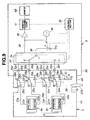
- Fig. 9 shows a configuration of an ultrasound endoscope 3 and an observation apparatus 6 in an ultrasound diagnostic system according to a second embodiment of the present invention corresponding to this case.
- switches 25i and 25i' that form a pair (instead of the switch 25i in Fig. 2B ) are provided via a connection section 26 connected to a lever 27B in the configuration of Fig. 2B .
- a common contact c of the switch 25i is connected to a lower electrode 22i via a signal line 24i and a common contact c' of the switch 25i' is connected to the upper electrode 21i via a signal line 23i.
- a contact b of the switch 25i is connected to a ground via a resistor R of a discharge section 31 via a signal line 30i and a contact b' of the switch 25i' is connected to the ground via a signal line 30i'. Furthermore, a contact a of the switch 25i and a contact a' of the switch 25i' are connected to connection contacts 29i and 29i' of a connector 4A via signal lines 28i and 28i' respectively.
- connection contact 32i of a connector receiver 5B connected to a connection contact 29i of the connector 4A is connected to a DC bias voltage generation section 37 via a signal line 33i, a multiplexer 34 and a signal line 38.
- connection contact 32i' of the connector receiver 5B connected to the connection contact 29i' of a connector 4B is connected to a transmission signal generation section 36 and an input end of an amplifier 40 via the signal line 33i', a multiplexer 34' and a signal line 38'. Switching of the multiplexers 34 and 34' is controlled by a control section 39.
- the present embodiment adopts a configuration with no capacitor 42 in Fig. 2B .
- the lever 27B, the connection section 26 and the switches 25i and 25i' of the present embodiment shown in Fig. 9 can be formed in a configuration similar to that shown, for example, in Fig. 6 and Fig. 8 .
- connection contacts 29i and 32i described in Fig. 6 and Fig. 8 may also be applied to the connection contacts 29i' and 32i' added from the connection contacts 29i and 32i of the first embodiment.
- the common contacts c and c' of the switches 25i and 25i' are connected to the contacts a and a' respectively. That is, also in the present embodiment, in a predetermined mounting state in which the ultrasound endoscope 3 is connected to the observation apparatus 6, the common contacts c and c' of the switches 25i and 25i' are connected to the contacts a and a' as shown in Fig. 9 .
- the upper electrode 21i of each C-MUT element 9i making up the C-MUT 9 is connected to the transmission/reception signal system of the observation apparatus 6 via the switch 25i'. Furthermore, the lower electrode 22i of each C-MUT element 9i is connected to the DC bias voltage generation section 37 of the observation apparatus 6 via the switch 25i.
- Applying a transmission signal and a DC bias voltage from the observation apparatus 6 to the C-MUT element 9i allows ultrasound to be outputted from each C-MUT element 9i. Furthermore, an ultrasound tomographic image is displayed on the monitor 6B by performing signal processing on the echo signal received through each C-MUT element 9i.
- the ultrasound endoscope 3 can be disconnected from the observation apparatus 6 by turning the lever 27B and setting the connector 4B at a position where it can be disconnected from the connector receiver 5B (released position where the connection can be released) as in the case described in the first embodiment.
- the present embodiment adopts a configuration in which the switch 25i of the first embodiment is modified into a pair of the switches 25i and 25i', the present embodiment has substantially the same operations as those of the first embodiment. Moreover, the present embodiment has effects similar to those of the first embodiment.
- Fig. 9 a case with the electronic scan ultrasound endoscope 3 has been described, but it is obvious that the present invention is also applicable to a case with a mechanical scan ultrasound probe unit 2. That is, one of the plurality of C-MUT elements 9i making up the C-MUT 9 in Fig. 9 is replaced with the C-MUT 10, and similar operation and effects can be obtained in this case, too.
- a configuration may also be adopted in which the contact b' of the switch 25i' in Fig. 9 is connected to the ground via a discharge device that discharges the charge.
- the signal line 23 i connected to the upper electrode 21i is changed to the signal line 28i' side of the contact a' and the discharge device side of the contact b' through the switching by the switch 25i' in conjunction with the operation of the lever 27B.
- Fig. 10 shows a lever 59 provided with a button 61 to change the switch 25 (25i in the case of the ultrasound endoscope 3) of the ultrasound probe unit 2 and a state in which the button is pressed determines whether the turning of the lever 59 is regulated or not.
- a white circle represents a state of the button 61 in which the button 61 is not pressed and a black circle represents a state of the button 61 in which the button 61 is pressed.
- the switch 25 is connected to a DC bias/transmission/reception section 62 on the observation apparatus 6 side.
- the DC bias/transmission/reception section 62 represents the DC bias voltage generation section 37 connected to the signal line 33, the transmission signal generation section 36 connected via the capacitor 42, the amplifier 40 and the reception processing section 41 in Fig. 2A .
- the DC bias/transmission/reception section 62 represents the multiplexer 34 connected to the signal line 33i, the DC bias voltage generation section 37, the transmission signal generation section 36 connected via the capacitor 42, the amplifier 40 and the reception processing section 41 in Fig. 2B .
- the switch 25 is connected to the discharge section 31 side.
- a structure is adopted for the lever 59 in such a configuration in which the lever 59 cannot be turned unless the button 61 is pressed (state shown by the black circle in Fig. 10 ) and the ultrasound probe unit 2 cannot be disconnected from the observation apparatus 6 unless the lever 59 is turned.
- Fig. 11 shows this state.
- the left figure of Fig. 11 shows a state in which the ultrasound probe unit 2 and the observation apparatus 6 are unconnected. Since the button 61 of the lever 59 is pressed, the switch 25 is connected to the discharge section 31 and the horizontal position of the lever 59 indicates that the ultrasound probe unit 2 is not connected to the observation apparatus 6.
- FIG. 11 shows a state in which the ultrasound probe unit 2 and the observation apparatus 6 are connected.
- the lever 59 is turned to an upright position indicating that the ultrasound probe unit 2 is connected to the observation apparatus 6.
- the switching state of the switch 25 remains as shown in the lower part of Fig. 10 .
- the right figure of Fig. 11 indicates that the button 61 of the lever 59 is operated to be set (changed) to a state in which the button 61 is not pressed, showing that the ultrasound probe unit 2 is connected to the observation apparatus 6 in a predetermined mounting state and that the switch 25 in Fig. 10 is changed to the DC bias/transmission/reception section 62 side.
- the operation for disconnecting the ultrasound probe unit 2 from the observation apparatus 6 is opposite to these operations and by operating the button 61 to cause the switch 25i to be connected to the discharge section 31 (middle of Fig. 11 ) and then turning the lever 59, the ultrasound probe unit 2 can be disconnected from the observation apparatus 6.
- the ultrasound probe unit 2 when the ultrasound probe unit 2 is released (disconnected) from the observation apparatus 6, it is possible to get the discharge section 31 connected to the C-MUT 10 before the release.
- the present embodiment also has effects similar to those of the first embodiment and the second embodiment.
- the present embodiment is likewise applicable to a case with the electronic scan ultrasound endoscope 3 and can obtain similar effects.
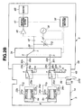
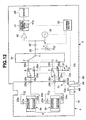
- Fig. 12 illustrates an ultrasound endoscope 3 and an observation apparatus 6 according to a fourth embodiment as such a configuration example.
- the present embodiment adopts a lever 59 provided with a button 61 on the ultrasound endoscope 3 side instead of the lever 27B in the configuration of Fig. 2B . Moreover, the switch 25i and the discharge section 31 provided on the ultrasound endoscope 3 side in Fig. 2B are set up on the observation apparatus 6.
- a signal line 24i connected to a lower electrode 22i is connected to a connection contact 29i
- a connection contact 32i is connected to a common contact c of the switch 25i provided inside the observation apparatus 6 via a signal line 70i.
- a contact a of the switch 25i is connected to a contact i of a multiplexer 34 via a signal line 33i.
- a contact b of the switch 25i is connected to the discharge section 31 via a signal line 30i.
- a transmission section 71 transmits control information for controlling the switch 25i or a control state to the switch 25i from the lever 59.
- ON/OFF by the pressing operation of the button 61 provided in the lever 59 is transmitted to the switch 25i inside the observation apparatus 6 via a signal line 72a, connection contacts 4d and 5d and a signal line 72b that form a transmission section 71.
- a configuration may also be adopted in which the transmission section 71 is connected to a control section 39 that manages the entire operation of the observation apparatus 6 via a signal line 72c connected to the signal line 72b. That is, the ON/OFF operation of the button 61 in the lever 59 may be transmitted to the control section 39.
- the control section 39 decides whether the button 61 of the lever 59 is pressed or not and sends the decision result to a reception processing section 41.
- the reception processing section 41 has an information display processing section 41a that generates an information display video signal to display information corresponding to the switching state of the switch 25i according to the decision result.
- the reception processing section 41 superimposes the information display video signal on a video signal of an ultrasound tomographic image, outputs the signal to a monitor 6B and the monitor 6B displays the information.
- control section 39 controls operations of a transmission signal generation section 36, a DC bias voltage generation section 37 and the reception processing section 41.
- the control section 39 may also perform a switching operation of the switch 25i according to the decision result of the button 61.
- switching between the contacts of the switch 25i may be directly performed using a signal through the operation of the button 61.
- the switch 25i may be configured as an electric switch, relay switch or the like.
- Fig. 13 illustrates a display example of information on the monitor 6B. While the ultrasound endoscope 3 is connected to the observation apparatus 6, for example, an information display area 19b of a peripheral section of a display area 19a of an ultrasound tomographic image on a screen of the monitor 6B as shown in Fig. 13(A) displays information such as a message "discharging.”
- This information need not always be displayed but may be displayed according to the display control operation from an operation section (not shown) that operates the observation apparatus 6.
- a message "not discharged” may be displayed on the monitor 6B in a large size as shown in Fig. 13(B) . After allowing the operator to discharge, a message may be given to the operator to guide the operator to perform a disconnection operation.
- the present embodiment has been described by taking a case of the electronic scan ultrasound endoscope 3, the present embodiment is also applicable to a case of the mechanical scan ultrasound probe unit 2.
- the present embodiment can obtain operation and effects similar to those of the electronic scan ultrasound endoscope 3.
- the ultrasound probe unit 2 may be adapted to an electronic scan configuration.
- a mechanical scan ultrasound endoscope may be adapted instead of the electronic scan ultrasound endoscope 3.
- the ultrasound probe unit 2 shown in Fig. 1 has a configuration in which the ultrasound probe 13 to be used inserted in the body is detachably attached to the drive unit 11, but a structure may also be adopted in which the ultrasound probe unit 2 is integrated with the drive unit 11.
- the ultrasound probe unit 2 may also be an ultrasound probe to be used outside the body.
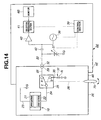
- Fig. 14 illustrates a configuration example of, for example, a mechanical scan ultrasound probe unit 2E and an observation apparatus 6E according to a fifth embodiment of the present invention.
- the present embodiment adopts, for example, a connector 4E and a connector receiver 5E as a connection section different from that in the first embodiment.
- the ultrasound probe unit 2E is mounted with one C-MUT 10 having the same configuration as that shown in Fig. 2A . Furthermore, as shown in Fig. 2A , a connection contact 32 in the observation apparatus 6E is connected to a DC bias voltage generation section 37 via a signal line 33.
- the connector 4E and the connector receiver 5E have a cylindrical connector housing (simply referred to as “housing”) 84E and a connector receiver housing (simply referred to as “housing”) 85E provided with a columnar concave section with which the cylindrical housing 84E is engaged.
- connection contact 29 is provided on a front end face of the housing 84E in Fig. 14 and the connection contact 32 which is in contact with and electrically connected to the connection contact 29 is provided on an innermost part of the concave section in the housing 85E.
- a rotatable lever 79 protrudes from a cylindrical side of the housing 84E.
- the housing 85E of the connector receiver 5E is provided with a guide groove 82a which serves as a guide when the housing 84E of the connector 4E is connected/disconnected (attached/detached).
- the housing 85E is provided with a circumferential groove 82b formed in a direction orthogonal to the guide groove 82a for a contact switching operation by the lever 79, setting the connector 4E and the connector receiver 5E in a locked state in conjunction with the switching operation and changing the locked state to a released state.
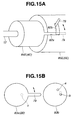
- the proximal end side of the lever 79 is connected to a rotor-side disk 83a arranged inside the housing of the connector 4E and rotated as shown in Fig. 15B to form a connection section 26 and a common contact c which forms a switch 25 connected to a signal line 24 is provided on one surface (back surface in Fig. 15B ) of the rotor-side disk 83a.
- stator-side disk 83b Opposite to the rotor-side disk 83a, a stator-side disk 83b that contacts the rotor-side disk 83a is arranged, and a contact a and a contact b that selectively contact and are electrically connected to the common contact c through the turning operation of the lever 79 are formed in the stator-side disk 83b.
- Both disks 83a and 83b are formed of an insulating member. Furthermore, signal lines connected to the contacts a and b, and the common contact c are omitted in Fig. 15B .
- the common contact c is set to a state in which the common contact c is electrically connected to the contact b as shown by a dotted line in Fig. 14 . Furthermore, there is such a structure that the connector 4E cannot be disconnected from the connector receiver 5E unless the lever 79 is set to the released position as described above.
- the present embodiment can realize a structure provided with the function described in the third embodiment.
- the connector 4E When the ultrasound probe unit 2E is used, connected to the observation apparatus 6E to perform an ultrasound inspection, the connector 4E is engaged with the connector receiver 5E and the lever 79 is then set to a lock position. As shown in Fig. 14 , the common contact c of the switch 25 is electrically connected to the contact a.
- the C-MUT 10 of the ultrasound probe unit 2E is ready to be driven by the observation apparatus 6E.
- a transmission signal from a transmission signal generation section 36 is then superimposed on a DC bias voltage via the signal line 33 and outputted to the ultrasound probe unit 2E side.
- Ultrasound reflected by a part of the subject where an acoustic impedance is changing is received by the C-MUT 10 and becomes an echo signal.
- the echo signal superimposed on the DC bias voltage passes through the switch 25, the DC bias voltage thereof is cut by the capacitor 42 and the signal is amplified by the amplifier 40.
- the echo signal amplified by the amplifier 40 is subjected to signal processing by the reception processing section 41, converted to a video signal, and then outputted to the monitor 6B and an ultrasound tomographic image is displayed on the display screen of the monitor 6B.
- the operator After performing the ultrasound inspection using ultrasound, the operator turns OFF the power to the observation apparatus 6E to stop the function of transmitting/receiving ultrasound (and the function of generating a DC bias voltage).
- the lever 79 When the ultrasound probe unit 2E is disconnected from the observation apparatus 6E, the lever 79 is turned to a released position shown by the dotted line in Fig. 15A , and it is thereby possible to disconnect the connector 4E of the ultrasound probe unit 2E from the connector receiver 5E of the observation apparatus 6E.
- the common contact c of the switch 25 is connected to the contact b, that is, a resistor R making up a discharge section 31 via the connection section 26.
- the charge of the C-MUT 10 is discharged to ground in Fig. 14 via the resistor R of the discharge section 31. It is thereby possible to eliminate the charge present in the C-MUT 10.
- the present embodiment since the charge present in the C-MUT 10 can be eliminated, it is possible to reliably prevent deterioration of the contact due to discharge when the connector 4E is disconnected from the connector receiver 5E caused by the charge present in the C-MUT 10 or eliminate the possibility that a high voltage during discharge may damage the transmission/reception processing system that performs transmission/reception in the observation apparatus 6E.
- the present embodiment it is possible to reduce or prevent the advance of deterioration of the C-MUT 10 device itself due to the charge accumulated for a long time in the capacitive micromachined ultrasonic transducer (C-MUT) 10.
- the present embodiment prevents the charge from being accumulated in the C-MUT 10 device, and can thereby secure stable sensitivity for a long period of time.
- the present embodiment can also realize an ultrasound diagnostic system with a high level of reproducibility.
- the connector 4E cannot be disconnected from the connector receiver 5E when the connector 4E is connected to the connector receiver 5E and the lever 79 is set to a lock position, it is thereby possible to reliably prevent the ultrasound probe unit 2E from being carelessly disconnected from the observation apparatus 6E during an ultrasound inspection.
- the present embodiment can provide an ultrasound diagnostic system with a high level of operability and reliability.
- the present embodiment may be adapted to have a configuration having effects similar to those of the aforementioned third embodiment.
- an arc-shaped contact that extends in the direction of the contact a as shown by a two-dot dashed line may be adopted.
- the C-MUT 10 is electrically connected to the discharge section 31 in the connection state of the switch 25 at the released position.
- An embodiment formed by partially combining the configurations of the aforementioned embodiments or the like also belongs to the present invention.
Landscapes
- Engineering & Computer Science (AREA)
- Health & Medical Sciences (AREA)
- Life Sciences & Earth Sciences (AREA)
- Physics & Mathematics (AREA)
- Pathology (AREA)
- Heart & Thoracic Surgery (AREA)
- Mechanical Engineering (AREA)
- Multimedia (AREA)
- Biophysics (AREA)
- Nuclear Medicine, Radiotherapy & Molecular Imaging (AREA)
- Acoustics & Sound (AREA)
- Radiology & Medical Imaging (AREA)
- Biomedical Technology (AREA)
- Computer Networks & Wireless Communication (AREA)
- Medical Informatics (AREA)
- Molecular Biology (AREA)
- Surgery (AREA)
- Animal Behavior & Ethology (AREA)
- General Health & Medical Sciences (AREA)
- Public Health (AREA)
- Veterinary Medicine (AREA)
- Ultra Sonic Daignosis Equipment (AREA)
- Transducers For Ultrasonic Waves (AREA)
Abstract
Description
- The present invention relates to an ultrasound diagnostic system using a capacitive micromachined ultrasonic transducer.
- An ultrasonic transducer using a capacitive micromachined ultrasonic transducer (hereinafter referred to as "C-MUT"), which is different from a piezoelectric transducer, has recently been developed, and an ultrasound diagnostic system is being proposed which is used for an inspection using ultrasound with an ultrasound probe or ultrasound endoscope mounted with the ultrasonic transducer connected therewith.
- The C-MUT has a structure in which one cavity is provided in a silicon substrate and electrodes are provided on and below the cavity, and by applying an ultrasound drive signal (or transmission signal) together with a bias voltage to these electrodes, a film above the cavity is made to vibrate to transmit ultrasound, a returned echo signal is detected with the upper film and transmission/reception of ultrasound is thereby realized.
- Since the C-MUT has a structure using a capacitive micromachined ultrasonic transducer, the C-MUT is liable to store charge and when the C-MUT continuously drives ultrasound for a long time, a certain amount of charge is accumulated.
- In order to alleviate disadvantages of the deterioration in electric acoustic conversion efficiency in the upper film due to the accumulation of charge, International Publication No.
2007/029357 as a first related art discloses that sensitivity during transmission/reception is corrected by monitoring the amount of charge. - In the above first related art, since the state where the charge is accumulated is maintained in a state where the ultrasound probe equipped with the C-MUT is detached from the ultrasound observation apparatus, the electric acoustic conversion efficiency is deteriorated. Therefore, in the state where the ultrasound probe equipped with the C-MUT is detached from the ultrasound observation apparatus, it has been desired to make an improvement for canceling the accumulation of the charge.
- Furthermore, as a second related art, International Publication No.
2005/120359 discloses means for adjusting a DC bias voltage when the DC bias voltage is superimposed on a high frequency pulse as a transmission signal and applied to the C-MUT. However, this second related art also has the same defect as the above first related art with respect to the state where the ultrasound probe equipped with the C-MUT is detached from the ultrasound observation apparatus. - In the ultrasound diagnostic system comprising the ultrasound device with the C-MUT, such as the ultrasound prove equipped with the C-MUT, it is necessary to detach the ultrasound device from the connection with the ultrasound observation apparatus by an operator such as surgeon in order to clean the used ultrasound device after finishing the inspection using ultrasound. Under the circumstance, it is convenient for the operator to release the connection without paying attention to the charge in the C-MUT.
- Further, it is conceivable that the operator may release the connection of the ultrasound device with the ultrasound observation apparatus by mistake during the diagnosis. In such a case, an influence of the charge accumulated in the C-MUT acts as static electricity on the ultrasound observation apparatus side depending on a contact state of terminals when the ultrasound device is detached from the ultrasound observation apparatus, and there is a possibility of causing damage to the circuit system.
- Further, there is also a problem that the charge accumulated in the C-MUT in the state where the ultrasound probe is detached from the ultrasound observation apparatus causes aged deterioration in elements of the C-MUT themselves so that a stable sensibility can not be reproduced.
- The present invention has been made in view of the above points and an object of the present invention is to provide an ultrasound diagnostic system capable of preventing accumulation of the charge in a capacitive micromachined ultrasonic transducer when an ultrasound device equipped with the capacitive micromachined ultrasonic transducer is detached from an ultrasound observation apparatus.
- An ultrasound diagnostic system according to one aspect of the present invention comprises: an ultrasound device mounted with a capacitive micromachined ultrasonic transducer; and a connection section for detachably connecting the ultrasound device and an ultrasound observation apparatus provided with a transmission signal generation section that generates a transmission signal to drive the capacitive micromachined ultrasonic transducer, wherein the ultrasound diagnostic system includes: a discharge section for discharging charge applied to the capacitive micromachined ultrasonic transducer; and a switching section arranged on a signal line between the capacitive micromachined ultrasonic transducer and the ultrasound observation apparatus, and wherein when the ultrasound device is set to a predetermined mounting state with respect to the ultrasound observation apparatus, correspondingly to a connecting state of the connection section between the ultrasound device and the ultrasound observation apparatus, the capacitive micromachined ultrasonic transducer is electrically connected to the transmission signal generation section via the signal line, and when the ultrasound device is to be detached from the ultrasound observation apparatus, switching of the switching section is performed so as to be a state in which the charge of the capacitive micromachined ultrasonic transducer is discharged by the discharge section.
-
-
Fig. 1 is a schematic diagram illustrating an overall configuration of an ultrasound diagnostic system according to a first embodiment of the present invention; -
Fig. 2A is a configuration diagram illustrating an internal configuration of an electric system of an observation apparatus and an ultrasound probe unit of the first embodiment; -
Fig. 2B is a configuration diagram illustrating an internal configuration of an electric system of the observation apparatus and an ultrasound endoscope of the first embodiment; -
Fig. 2C is a configuration diagram illustrating a configuration example of a peripheral section of a transmission signal generation section of an observation apparatus in a modification example in the case of an electronic scan; -
Fig. 3A is a diagram illustrating a case where the connector of the ultrasound probe unit is connected to the connector receiver of the observation apparatus; -
Fig. 3B is a diagram illustrating a case where the connector of the ultrasound probe unit is disconnected from the connector receiver of the observation apparatus; -
Fig. 4A is a diagram illustrating a case where the connector of the ultrasound endoscope is connected to the connector receiver of the observation apparatus; -
Fig. 4B is a diagram illustrating a case where the connector of the ultrasound endoscope is disconnected from the connector receiver of the observation apparatus; -
Fig. 5 is a diagram illustrating a schematic configuration when the connection pin of the connector of the ultrasound probe is connected to the connection pin of the connector receiver through a lever operation; -
Fig. 6 is a diagram illustrating a schematic configuration when the connection pin of the connector of the ultrasound endoscope is connected to the connection pin of the connector receiver through a lever operation; -
Fig. 7 is a schematic diagram illustrating a case where a switch is changed in conjunction with an operation of connecting the connection pin of the connector of the ultrasound probe unit to the connection pin of the connector receiver through a lever operation in correspondence withFig. 5 ; -
Fig. 8 is a schematic diagram illustrating a case where a switch is changed in conjunction with an operation of connecting the connection pin of the connector of the ultrasound endoscope to the connection pin of the connector receiver through a lever operation in correspondence withFig. 6 ; -
Fig. 9 is a configuration diagram illustrating a configuration of an ultrasound endoscope and an observation apparatus according to a second embodiment of the present invention; -
Fig. 10 is a diagram illustrating in a table form the status of a button for switching a contact point of the switch provided in the lever and contents of the switching state of the switch according to a third embodiment of the present invention; -
Fig. 11 is a diagram illustrating a state as to whether the button provided on the lever is pressed or not and a connection/disconnection relationship between the ultrasound probe unit and the observation apparatus; -
Fig. 12 is a configuration diagram illustrating a configuration of an ultrasound probe unit and an observation apparatus according to a fourth embodiment of the present invention; -
Fig. 13 is a diagram illustrating an example where information of a setting state of the switch or the like is displayed on a monitor according to the fourth embodiment; -
Fig. 14 is a configuration diagram illustrating a configuration of an ultrasound probe unit and an observation apparatus according to a fifth embodiment of the present invention; -
Fig. 15A is a perspective view illustrating a locked state in which the connector of the ultrasound probe unit inFig. 14 is connected and fixed to the connector receiver of the observation apparatus; and -
Fig. 15B is a diagram illustrating a rotor side disk connected to the rotary lever and a stator side disk that contacts the rotor side disk, arranged inside the connector. - Hereinafter, embodiments of the present invention will be described with reference to the accompanying drawings.
-
Fig. 1 illustrates an overall configuration of an ultrasounddiagnostic system 1 according to a first embodiment of the present invention. The ultrasounddiagnostic system 1 includes anultrasound probe unit 2 as an ultrasound device for inspecting a subject using ultrasound and anultrasound endoscope 3 as an ultrasound device inserted into the body cavity of the subject and provided with a function of performing an inspection using ultrasound and an endoscope function. - Furthermore, the ultrasound
diagnostic system 1 is provided withconnector receivers connectors ultrasound probe unit 2 and theultrasound endoscope 3 are detachably connected and is also constructed of an ultrasound observation apparatus body (hereinafter simply abbreviated as "observation apparatus body") 6A provided with a transmission/reception signal processing system that transmits/receives ultrasound and amonitor 6B as a display apparatus. Theobservation apparatus body 6A and themonitor 6B constitute anobservation apparatus 6. - The
ultrasound probe unit 2 includes anultrasound probe 13 incorporating, for example, a mechanical scan capacitive micromachined ultrasonic transducer (hereinafter abbreviated as "C-MUT") 10 as an ultrasonic transducer for transmitting/receiving ultrasound, an ultrasound probe drive unit (hereinafter abbreviated as "drive unit") 11 to which theultrasound probe 13 is detachably connected and acable section 12 that extends from thedrive unit 11. Theconnector 4A detachably connected to the above describedconnector receiver 5A is provided at an end of thecable section 12. Theconnector receiver 5A constitutes a connection section to which an ultrasound device driven according to a mechanical scan scheme such as theultrasound probe unit 2 is detachably connected. - On the other hand, the above described
connector receiver 5B constitutes a connection section of an ultrasound device driven according to an electronic scan such as theultrasound endoscope 3. - The
ultrasound endoscope 3 is provided with aninsertion portion 14 inserted into the body cavity of the subject, anoperation section 15 provided at a rear end (proximal end) of theinsertion portion 14 and auniversal cable section 16 that extends from theoperation section 15. - An
endoscope connector 17 connected to an endoscope light source device (not shown) and a processor is provided at an end of theuniversal cable section 16. Acable section 18 extends from theendoscope connector 17 and theconnector 4B detachably connected to the above describedconnector receiver 5B is provided at an end of thecable section 18. - For example, an electronic scan C-
MUT 9 as an ultrasonic transducer for transmitting/receiving ultrasound is provided at adistal end portion 19 provided at a distal end of theinsertion portion 14 of the above describedultrasound endoscope 3. - A C-
MUT 10 mounted at a distal end portion of theultrasound probe 13 in theultrasound probe unit 2 performs, for example, radial mechanical scan and the C-MUT 9 mounted on theultrasound endoscope 3 performs, for example, sector electronic scan. -
Fig. 2A illustrates an internal configuration of the electric system of theultrasound probe unit 2 and theobservation apparatus 6 in an operating state andFig. 2B illustrates an internal configuration of the electric system of theultrasound endoscope 3 and theobservation apparatus 6 in an operating state. - As shown in
Fig. 2B , in (thedistal end portion 19 of) theinsertion portion 14 of theultrasound endoscope 3, for example, a plurality of C-MUT elements 9a, ... , 9n are arranged along a curved surface to form the sector electronic scan C-MUT 9. - In each C-MUT element 9i (i = a, ... , n), an upper electrode 21i and a lower electrode 22i are formed facing each other across a cavity. The upper electrode 21i in each C-MUT element 9i is connected to a ground (G in
Fig. 2B ), that is, grounded via a signal line 23i. - On the other hand, a DC bias voltage and a transmission signal (also referred to as "drive signal") are applied to the lower electrode 22i from the
observation apparatus 6 via asignal line 24i in the operating state shown inFig. 2B . - In the present embodiment, the
signal line 24i, one end of which is connected to the lower electrode 22i is connected to a common contact c of a switch 25i provided, for example, in theconnector 4B and the common contact c of each switch 25i is selectively connected with one of two contacts a and b. - Each switch 25i is connected to a
lever 27B that operates to connect or disconnect theultrasound endoscope 3 to/from theobservation apparatus 6 via aconnection section 26. - Furthermore, the contact a of each switch 25i is connected to a
connection contact 29i of theconnector 4B via a signal line 28i and the contact b of each switch 25i is connected to one end of asignal line 30i and thesignal line 30i is connected to the ground, that is, grounded via a resistor R making up adischarge section 31. - On the other hand, the
connector receiver 5B of theobservation apparatus 6 is provided with aconnection contact 32i connected to the above describedconnection contact 29i and eachconnection contact 32i is connected to a contact i of themultiplexer 34 via asignal line 33i. - The contact i of the
multiplexer 34 is selectively connected to the common contact c sequentially from contact a to n under the switching control of acontrol section 39. The common contact c is connected to one end of asignal line 38. - Furthermore, the
observation apparatus 6 includes a transmissionsignal generation section 36 that generates a transmission signal (drive signal) for sequentially driving each C-MUT element 9i making up the above described C-MUT 9 and transmitting ultrasound in a sector form. Furthermore, theobservation apparatus 6 includes a DC biasvoltage generation section 37 that generates a DC bias voltage to be superimposed on the transmission signal and outputs the transmission signal and the DC bias voltage to theultrasound endoscope 3 side via thesignal line 38,multiplexer 34 or the like. - When an operator operates a DC bias voltage adjustment knob or the like, the DC bias
voltage generation section 37 generates a DC bias voltage of an adjusted value. The DC biasvoltage generation section 37 may also be enabled to adjust a DC bias voltage generated under the control of thecontrol section 39. - Furthermore, the
observation apparatus 6 includes anamplifier 40 that amplifies an ultrasound echo signal (simply referred to as "echo signal") as a received signal received by each C-MUT element 9i of the C-MUT 9 and converted from ultrasound to an electric signal and areception processing section 41 that performs signal processing on the echo signal as the received signal and generates a video signal. - The video signal outputted from the
reception processing section 41 is outputted to themonitor 6B as display means and themonitor 6B displays an ultrasound tomographic image corresponding to the video signal. - Furthermore, a
capacitor 42 is provided at some midpoint on thesignal line 38 which prevents the DC bias voltage of the DC biasvoltage generation section 37 from being applied to the transmissionsignal generation section 36 and theamplifier 40. Thecontrol section 39 controls operations of the transmissionsignal generation section 36, the DC biasvoltage generation section 37, thereception processing section 41 and the like. - In the
observation apparatus 6 according to the electronic scan shown inFig. 2B , the transmissionsignal generation section 36 may also be constructed of, for example, a plurality of transmissionsignal generation sections 36a, ... 36q as shown inFig. 2C , and similarly theamplifier 40 inFig. 2B may also be constructed of a plurality ofamplifiers 40a, ... 40q as shown inFig. 2C . - A configuration may also be adopted in which transmission signal generation timings of the plurality of transmission
signal generation sections 36a, ... 36q may be shifted so that the plurality of C-MUT elements 9i are simultaneously driven via thecapacitors 42a, ... 42q and themultiplexer 34A. - Furthermore, in this case, echo signals received by the plurality of C-MUT elements 9i are amplified by the
amplifiers 40a, ... 40q and outputted to thereception processing section 41. This makes it possible to scan or cause to converge ultrasound in a direction different from the array shape of the plurality of C-MUT elements 9a, 9b, ... 9n. - In this case, the DC bias
voltage generation section 37 inFig. 2B may be constructed of a plurality of DC biasvoltage generation sections 37a, ... 37q as shown inFig. 2C and themultiplexer 34A may also be constructed so as to switch between signal lines 38i in units of a plurality of signal lines. The configuration inFig. 2C may also be applied to other embodiments inFig. 9 or the like as will be described later. - On the other hand, in the case of the
ultrasound probe unit 2 shown inFig. 2A , one C-MUT 10 is arranged inside theultrasound probe 13 and the C-MUT 10 is driven to rotate by a motor (not shown) or the like and ultrasound is then radially subjected to radial mechanical scanning. - The C-
MUT 10 has a configuration corresponding to one C-MUT element 9i in the C-MUT 9 inFig. 2B . That is, in the C-MUT 10, anupper electrode 21 and alower electrode 22 are formed so as to face each other across the cavity. Theupper electrode 21 in the C-MUT 10 is connected to the ground (G inFig. 2A ), that is, grounded via thesignal line 23. - On the other hand, in the operating state shown in
Fig. 2A , a DC bias voltage and a transmission signal are applied to thelower electrode 22 from theobservation apparatus 6 side via asignal line 24. - In the present embodiment, the
signal line 24, one end of which is connected to thelower electrode 22, is connected, for example, to a common contact c of aswitch 25 provided in aconnector 4A and the common contact c of theswitch 25 is selectively connected to one of the two contacts a and b. - The
switch 25 is connected to alever 27A that connects or disconnects theultrasound probe unit 2 to/from theobservation apparatus 6 via aconnection section 26. - Furthermore, the contact a of the
switch 25 is connected to aconnection contact 29 of theconnector 4A via asignal line 28, the contact b of theswitch 25 is connected to one end of asignal line 30, and thesignal line 30 is connected to the ground, that is, grounded via a resistor R making up adischarge section 31. - On the other hand, a
connector receiver 5A of theobservation apparatus 6 is provided with aconnection contact 32 connected to the above describedconnection contact 29 and theconnection contact 32 is connected to a DC biasvoltage generation section 37 via asignal line 33. - Furthermore, the
observation apparatus 6 includes a transmissionsignal generation section 36 that generates a transmission signal (drive signal) for driving the above described C-MUT 10 to transmit ultrasound and the DC biasvoltage generation section 37 that generates a DC bias voltage to be superimposed on the transmission signal, and outputs the transmission signal and the DC bias voltage to theultrasound probe unit 2 side via thesignal line 33. - Furthermore, the
observation apparatus 6 includes anamplifier 40 that amplifies an echo signal as a received signal received by the C-MUT 10 and converted from ultrasound to an electric signal and areception processing section 41 that performs signal processing on the echo signal and generates a video signal. - A video signal outputted from the
reception processing section 41 is outputted to amonitor 6B as display means and themonitor 6B displays an ultrasound tomographic image corresponding to the video signal. - Furthermore, a
capacitor 42 is provided at some midpoint on thesignal line 33 which prevents the DC bias voltage of the DC biasvoltage generation section 37 from applying to the transmissionsignal generation section 36 and theamplifier 40. Acontrol section 39 controls operations of the transmissionsignal generation section 36 and thereception processing section 41 and the like according to theultrasound endoscope 3 orultrasound probe unit 2 connected to theobservation apparatus 6. - The present embodiment may also adopt a configuration in which the transmission
signal generation section 36, the DC biasvoltage generation section 37, thereception processing section 41 and the like of theobservation apparatus 6 are used in common between the C-MUTs signal generation section 36 and the like may be provided in correspondence with theultrasound endoscope 3 and theultrasound probe unit 2. -
Fig. 3A and Fig. 3B illustrate how the operator connects or disconnects theconnector 4A of theultrasound probe unit 2 to/from theobservation apparatus 6. As shown inFig. 3A , when mounting (connecting) theconnector 4A of theultrasound probe unit 2 on (to) theobservation apparatus 6, the operator inserts theconnector 4A on (theconnector receiver 5A of) theobservation apparatus 6 side as shown by a blank arrow. - After the insertion, the operator turns the
lever 27A as shown by an arrow. The turning of thelever 27A changes the state of theconnection contact 29 of theconnector 4A which is not connected to theconnection contact 32 of theconnector receiver 5A to a predetermined mounting state in which theconnection contact 29 is connected to theconnection contact 32. - Furthermore, when unmounting the
connector 4A of theultrasound probe unit 2 mounted on theconnector receiver 5A of theobservation apparatus 6, the operator performs an operation opposite to that inFig. 3A as shown inFig. 3B . That is, as shown inFig. 3B , the operator turns thelever 27A in a direction opposite to that inFig. 3A . This turning operation unlocks the mounting state and also causes theconnection contact 29 of theaforementioned connector 4A to change the state in which theconnection contact 29 is connected to theconnection contact 32 of theconnector receiver 5A to a state in which theconnection contact 29 is not connected and is ready to be disconnected (also referred to as "released state"). - After that, the operator pulls out the
connector 4A from (theconnector receiver 5A of) theobservation apparatus 6 side as shown by a blank arrow, and can thereby disconnect theconnector 4A from theconnector receiver 5A of theobservation apparatus 6. Thus, theconnector 4A and theconnector receiver 5A making up the connection section of the present embodiment are provided with a lock mechanism that keeps a locked state of preventing or regulating disconnection of theconnector 4A from theconnector receiver 5A (due to careless disconnection operation) in a predetermined mounting state and releases the locked state in a released state set by the turning operation of thelever 27A. The followingconnector 4B andconnector receiver 5B are likewise provided with the lock mechanism. - Furthermore,
Fig. 4A andFig. 4B are diagrams illustrating a case where theconnector 4B of theultrasound endoscope 3 is connected or disconnected to/from theconnector receiver 5B of theobservation apparatus 6, that is, a case where theconnector 4B is attached/detached. As is clear from a comparison withFig. 3A and Fig. 3B , the attachment/detachment operation is the same as the attachment/detachment operation of theconnector 4A of theultrasound probe unit 2 to/from theconnector receiver 5A of theobservation apparatus 6 and the operation thereof is also the same. -
Fig. 5 illustrates a structure example in which the operation of theaforementioned lever 27A causes acontact pin 51 as theconnection contact 29 of theconnector 4A to be attached/detached to/from acontact pin 52 as theconnection contact 32 in theconnector receiver 5A of theobservation apparatus 6. -
Fig. 5(A) shows an unconnected state in which thecontact pin 51 of theconnector 4A is separate from thecontact pin 52 of theconnector receiver 5A,Fig. 5(B) shows a state in which although theconnector 4A is inserted into and connected to theconnector receiver 5A, thecontact pin 51 is not connected to thecontact pin 52 andFig. 5(C) shows a predetermined mounting state in which thelever 27A in the state ofFig. 5(B) is turned and thecontact pin 51 is connected to thecontact pin 52 and locked. - As shown in
Fig. 5(A) or the like, theconnector 4A has ahousing 53 that accommodates the proximal end side of thecontact pin 51 and a contact pin holding frame (hereinafter, simply abbreviated as "holding frame") 54 provided at a distal end of thehousing 53, in which a substantially central portion in a longitudinal direction of thecontact pin 51 is inserted and from which the distal end side of thecontact pin 51 protrudes. - The holding
frame 54 is moved by a rotatingellipsoidal cam 55 in the direction (vertical direction inFig. 5 ) orthogonal to the longitudinal direction of the contact pin 51 (horizontal direction inFig. 5 ) in conjunction with the turning operation of thelever 27A. - On the other hand, the
connector receiver 5A has ahousing 57 that includes aconcave section 56 having an opening into which thecontact pin 51 is inserted and accommodates thecontact pin 52 which is electrically connected to the distal end of thecontact pin 51 through contact therewith along the bottom of theconcave section 56. When thecontact pin 51 is inserted into theconnector receiver 5A as shown inFig. 5(B) , thecontact pin 51 is inserted along the top surface of theconcave section 56, and in this state, thecontact pin 51 is set so as not to contact (separate from) thecontact pin 52 disposed along the bottom surface of theconcave section 56. - Furthermore, in the state of
Fig. 5(B) , when thelever 27A is turned to cause thecam 55 to rotate 90° as shown inFig. 5(C) , an outer circumferential portion in the major axis direction of thecam 55 causes the holdingframe 54 to move downward. - The movement of the holding
frame 54 causes the central portion of thecontact pin 51 to be pressed downward by a convex section provided on an inner surface of the holdingframe 54. Since the proximal end side of thecontact pin 51 is regulated, thecontact pin 51 closer to the distal end side than the proximal end is deformed while moving downward, and in that case, the distal end of thecontact pin 51 moves downward and comes into contact with thecontact pin 52. - Furthermore, as described above, the state in
Fig. 5(C) is a predetermined mounting state in which the contact pins 51 and 52 remain in contact with each other, and the state in whichcontact pin 51 is in contact with thecontact pin 52 is kept and a locked state is in place in which even if the operator attempts to pull out theconnector 4A from theconnector receiver 5A, theconnector 4A cannot be disconnected. - On the other hand, in the case of the
connector 4B of theultrasound endoscope 3 and theconnector receiver 5B, there are as many configurations shown inFig. 5 as the number ofconnection contacts connection contacts 29a to 29n) and one of such configurations is as shown inFig. 6 . - The configuration shown in
Fig. 6 is similar to the case where theconnection contacts Fig. 5(A) are replaced by one set ofconnection contacts Fig. 5 have a structure in which these are replaced by one set ofcontact pins Fig. 6 . - In the case of the
connector 4B and theconnector receiver 5B, there are a plurality of sets of the contact pins 51i and 52i having the structure (shown by the surface of the sheet ofFig. 6 ) in the direction perpendicular to the surface of the sheet ofFig. 6 and a plurality of sets of theconnection contacts Fig. 6 together with thecam 55 that rotates in conjunction with the turning operation of thelever 27B. - The connector structure itself described with reference to
Fig. 5 andFig. 6 in which the contact pins 51 (51i) and 52 (52i) are detachably connected is a publicly known technique. - With such a structure, the present embodiment changes the destination of the common contact c of the
switches 25 and 25i from the contact a to the contact b or from the contact b to the contact a using thecam 55 or the like making up theconnection section 26 in conjunction with the turning operation of thelevers Fig. 2A andFig. 2B . - For this reason, in the present embodiment, the connection contact 29 (
contact pin 51 inFig. 5 ) inFig. 2A forms the common contact c of the switch 25 (seeFig. 6 ), and as shown inFig. 5 , acontact member 58b having the function of the contact b of theswitch 25 is provided, for example, at a position near the opening in the upper part of the inner surface of thehousing 53. - The
contact member 58b is electrically connected to thedischarge section 31 via thesignal line 30 as shown inFig. 5 andFig. 2A . Furthermore, the contact pin 52 (connection contact 32 inFig. 2A ) shown inFig. 5 is provided with the function of the contact a as theconnector receiver 5A. - Therefore, the electrical connection structure in the present embodiment corresponding to
Fig. 5(A) to Fig. 5(C) is as shown inFig. 7(A) to Fig. 7(C). Fig. 7(A) corresponds toFig. 5(A) and shows thecontact pin 51 having the function of theconnection contact 29 and the common contact c and thecontact pin 51 is not connected to theconnection contact 32 and thecontact pin 52 that makes up the contact a. - In this state, the
signal line 24 connected to thelower electrode 22 is electrically connected to thedischarge section 31 via thecontact member 58b that contacts the contact pin 51 (having the function of the contact b). - In the state of
Fig. 7(B) corresponding toFig. 5(B) , thecontact pin 51 is set at a position above thecontact pin 52. Furthermore, thecontact pin 51 in this state is in the same electric connection state as inFig. 7(A) . - When the
lever 27A is turned in the state ofFig. 5(B) , a state inFig. 5(C) is set, and in the state inFig. 7(C) corresponding toFig. 5(C) , thecontact pin 51 moves downward, detached from thecontact member 58b, the distal end of thecontact pin 51 comes into contact with thecontact pin 52 and is thereby electrically connected. - In the case of the
ultrasound endoscope 3, acontact member 58b is provided as shown inFig. 6 (as in the case ofFig. 5 ) and thecontact member 58b is electrically connected to thedischarge section 31 via thesignal line 30i as shown inFig. 6 andFig. 2B . - In correspondence with
Fig. 7 corresponding toFig. 5 in the case of theultrasound probe unit 2, the diagram corresponding toFig. 6 in the case of theultrasound endoscope 3 is as shown inFig. 8 . By renaming components inFig. 8 corresponding to those inFig. 5 andFig. 6 (e.g., readingreference numeral 29 as 29i, 30 as 30i, 32 as 32i, 33 as 33i, 51 as 51i and 52 as 52i), both operations become similar, and so descriptions thereof will be omitted. - As described above, although a difference between mechanical scan and electronic scan exists between the configuration of the
ultrasound probe unit 2 and theobservation apparatus 6 corresponding to theultrasound probe unit 2 that transmits/receives ultrasound and the configuration of theultrasound endoscope 3 and theobservation apparatus 6 corresponding to theultrasound endoscope 3 that transmits/receives ultrasound, these configurations are the same in the sense that they have principal features in the present embodiment. - For this reason, descriptions of the case corresponding to the
ultrasound endoscope 3 will be omitted. - Thus, in the present embodiment, when the
ultrasound probe unit 2 orultrasound endoscope 3 as the ultrasound device mounted with the C-MUT observation apparatus 6 to which the ultrasound device is detachably attached and which includes a transmission/reception processing system that performs transmission/reception signal processing on the C-MUT switches 25 and 25i is set to be connected to the contact a so that the C-MUT voltage generation section 37. - Furthermore, when the ultrasound device is disconnected from the
observation apparatus 6, the ultrasound device cannot be disconnected from theobservation apparatus 6 unless thelever switches 25 and 25i to be connected to the contact b of thedischarge section 31 side. That is, when the ultrasound device is mounted on theobservation apparatus 6 and ready for use, such a structure is provided that the ultrasound device cannot be carelessly disconnected from theobservation apparatus 6. - The ultrasound
diagnostic system 1 of the present embodiment in such a configuration includes theultrasound probe unit 2 or the ultrasound device made up of theultrasound endoscope 3 mounted with the capacitive micromachined ultrasonic transducer (C-MUT 10 or 9), theconnector 4A (or 4B) andconnector receiver 5A (or 5B) as the connection section for detachably connecting the ultrasound device and theobservation apparatus 6 provided with the transmissionsignal generation section 36 that generates a transmission signal to drive the C-MUT, thedischarge section 31 to discharge the charge applied to the C-MUT and theswitches 25 and 25i as the switching section arranged on the signal line between the C-MUT and theobservation apparatus 6. - When the ultrasound device is set to a predetermined mounting state with respect to the
observation apparatus 6 according to the attachment/detachment state of the connection section between the ultrasound device and theobservation apparatus 6, the C-MUT is electrically connected to the transmissionsignal generation section 36 via the signal line and when the ultrasound device is disconnected from theobservation apparatus 6, switching of theswitches 25 and 25i is performed so that the charge of the C-MUT is discharged by thedischarge section 31. - Operation of the present embodiment having such a configuration will be described.
- When the
ultrasound probe unit 2 is used connected to theobservation apparatus 6 to perform an ultrasound inspection, as shown inFig. 3A , theconnector 4A is inserted so as to engage with theconnector receiver 5A, and then thelever 27A is turned to set a predetermined mounting state. - The common contact c of the
switch 25 is electrically connected to the contact a (from the contact b via the contact member 58a) so that thesignal line 24 connected to thelower electrode 22 of the C-MUT 10 is connected to the contact pin 52 (connection contact 32) of theobservation apparatus 6 as shown inFig. 7(C) . - Therefore, the C-
MUT 10 of theultrasound probe unit 2 can be driven by theobservation apparatus 6. The operator sets the DC biasvoltage generation section 37 so as to output a DC bias voltage suitable for driving the C-MUT 10. - Through the
signal line 33 or the like, a transmission signal from the transmissionsignal generation section 36 is superimposed on the DC bias voltage and outputted to theultrasound probe unit 2 side. As shown inFig. 2A , since the common contact c is electrically connected to the contact a, the DC bias voltage on which the transmission signal is superimposed is applied to thelower electrode 22 of the C-MUT 10 and the mechanically scanned C-MUT 10 transmits ultrasound to the subject side. - Ultrasound reflected by a portion of the subject where an acoustic impedance is changing is received by the C-
MUT 10 and becomes an echo signal. - The echo signal superimposed on the DC bias voltage passes through the
switch 25, whose DC bias voltage is cut by thecapacitor 42 and the signal is then amplified by theamplifier 40. - The echo signal amplified by the
amplifier 40 is subjected to signal processing by thereception processing section 41, converted to a video signal, outputted to themonitor 6B and an ultrasound tomographic image is displayed on the display screen of themonitor 6B. - After the ultrasound inspection using ultrasound, the operator turns OFF the power to the
observation apparatus 6 to stop the function of transmitting/receiving ultrasound (and the function of generating a DC bias voltage). - When the
ultrasound probe unit 2 is disconnected from theobservation apparatus 6, thelever 27A is turned as shown inFig. 3B and it is thereby possible to disconnect theconnector 4A of theultrasound probe unit 2 from theconnector receiver 5A of theobservation apparatus 6. - In conjunction with the turning of the
lever 27A at this time, the common contact c of theswitch 25 is connected to the contact b, that is, the resistor R making up thedischarge section 31. As a result, the charge of the C-MUT 10 is discharged to ground via the resistor R of thedischarge section 31 shown inFig. 2A . This makes it possible to eliminate the charge present in the C-MUT 10. - Therefore, according to the present embodiment, when the
ultrasound probe unit 2 as the ultrasound device mounted with the C-MUT 10 as the capacitive micromachined ultrasonic transducer is disconnected from theobservation apparatus 6, it is possible to discharge and eliminate the charge so that the charge of the C-MUT 10 is not accumulated. - Furthermore, according to the present embodiment, (since the charge present in the C-
MUT 10 can be eliminated as described above), it is possible to reliably eliminate the possibility that the charge present in the C-MUT 10 may cause discharge when theconnector 4A is disconnected from theconnector receiver 5A causing deterioration of the contact (contact pin) or a high voltage at the time of discharge may damage the transmission/reception processing system that performs transmission/reception in theobservation apparatus 6. - Furthermore, according to the present embodiment, it is also possible to reduce or prevent the advance of deterioration of the C-
MUT 10 itself due to the charge accumulated in the capacitive micromachined ultrasonic transducer (C-MUT) 10 for a long time. Moreover, by preventing charge from being accumulated in the C-MUT 10, it is possible to ensure stable sensitivity for a long period of time. In addition, it is possible to realize an ultrasounddiagnostic system 1 with a high degree of reproducibility. - Furthermore, according to the present embodiment, when the
connector 4A and theconnector receiver 5A are connected and thelever 27A is set to a lock position, theconnector 4A cannot be disconnected from theconnector receiver 5A, and it is thereby possible to reliably prevent theultrasound probe unit 2 from being carelessly disconnected from theobservation apparatus 6 during an ultrasound inspection. The present embodiment can provide the ultrasounddiagnostic system 1 with a high degree of operability and reliability. - Furthermore, operation when the
ultrasound endoscope 3 is detachably connected to theobservation apparatus 6 also has similar operation and effects. In this case, by reading the C-MUT 10 as C-MUT 9 or C-MUT element 9i, switch 25 as 25i,lever 27A aslever 27B,connector 4A asconnector 4B,connector receiver 5A asconnector receiver 5B, similar operation and effects can be obtained. - For example, as shown in
Fig. 4A , when theconnector 4B of theultrasound endoscope 3 is attached to theconnector receiver 5B of theobservation apparatus 6, the operator inserts theconnector 4A on (theconnector receiver 5B of) theobservation apparatus 6 side as shown by a blank arrow. - After the insertion, the operator turns the
lever 27B as shown by the arrow. When thelever 27B is turned, as shown inFig. 8(A) and Fig. 8(B) , thesignal line 24i (connected to the lower electrode 22i of each C-MUT element 9i making up the C-MUT 9) connected to the contact b is changed to a state in which it is connected to thecontact pin 52i (connection contact 32i) of theobservation apparatus 6. - It is then possible to set a state in which the
observation apparatus 6 can transmit/receive ultrasound to/from the C-MUT 9 of theultrasound endoscope 3. - Furthermore, when the
connector 4B of theultrasound endoscope 3 connected to theconnector receiver 5B of theobservation apparatus 6 is disconnected, as shown inFig. 4B , operation opposite to that inFig. 4A is performed. That is, as shown inFig. 4B , the operator turns thelever 27B in the direction opposite to that inFig. 4A . - With this turning operation, the mounting state is unlocked and the
signal line 24i connected to the lower electrode 22i of each C-MUT element 9i making up the C-MUT 9 is changed to a state in which it is connected to the contact b. In this state, it is possible to discharge the charge accumulated in the electrode of each C-MUT element to ground through thedischarge section 31. - Furthermore, the operator performs operation of separating the
connector 4B from (theconnector receiver 5B of) theobservation apparatus 6 side, and can thereby disconnect theconnector 4B from theconnector receiver 5B of theobservation apparatus 6. The present embodiment provides effects similar to those in the case of the aforementionedultrasound probe unit 2. - In
Fig. 2A andFig. 2B , the resistor R is used as thedischarge section 31, but other devices such as a diode may also be used. - A configuration has been described above where the contacts a and b of the
switches 25 and 25i are changed in conjunction with the turning operation of thelever observation apparatus 6 are detachably connected through the turning operation of thelever lever switches 25 and 25i. - In the above configuration, the
observation apparatus 6 is provided with the connection section to detachably connect both mechanical scan and electronic scan ultrasound devices, but the present invention is not limited to such a configuration and it is obvious that the present invention is also applicable to an observation apparatus in which any one of those scan ultrasound devices is detachably connected to the ultrasound device. - The configuration shown in
Fig. 2A andFig. 2B has been described as a configuration in which a DC bias voltage and a transmission signal are applied to thelower electrodes 22 and 22i of the C-MUT MUT 9 and a DC bias voltage is applied to the lower electrode 22i side. -
Fig. 9 shows a configuration of anultrasound endoscope 3 and anobservation apparatus 6 in an ultrasound diagnostic system according to a second embodiment of the present invention corresponding to this case. In the configuration shown inFig. 9 , switches 25i and 25i' that form a pair (instead of the switch 25i inFig. 2B ) are provided via aconnection section 26 connected to alever 27B in the configuration ofFig. 2B . - A common contact c of the switch 25i is connected to a lower electrode 22i via a
signal line 24i and a common contact c' of the switch 25i' is connected to the upper electrode 21i via a signal line 23i. - Furthermore, a contact b of the switch 25i is connected to a ground via a resistor R of a
discharge section 31 via asignal line 30i and a contact b' of the switch 25i' is connected to the ground via asignal line 30i'. Furthermore, a contact a of the switch 25i and a contact a' of the switch 25i' are connected toconnection contacts connector 4A via signal lines 28i and 28i' respectively. - Furthermore, a
connection contact 32i of aconnector receiver 5B connected to aconnection contact 29i of theconnector 4A is connected to a DC biasvoltage generation section 37 via asignal line 33i, amultiplexer 34 and asignal line 38. - Furthermore, a
connection contact 32i' of theconnector receiver 5B connected to theconnection contact 29i' of aconnector 4B is connected to a transmissionsignal generation section 36 and an input end of anamplifier 40 via thesignal line 33i', a multiplexer 34' and a signal line 38'. Switching of themultiplexers 34 and 34' is controlled by acontrol section 39. - The present embodiment adopts a configuration with no
capacitor 42 inFig. 2B . - The
lever 27B, theconnection section 26 and the switches 25i and 25i' of the present embodiment shown inFig. 9 can be formed in a configuration similar to that shown, for example, inFig. 6 andFig. 8 . - That is, a configuration similar to that of the
connection contacts Fig. 6 andFig. 8 may also be applied to theconnection contacts 29i' and 32i' added from theconnection contacts - As described in the first embodiment, when the mounting state is set in which the
lever 27B is locked as shown inFig. 6(C) , the common contacts c and c' of the switches 25i and 25i' are connected to the contacts a and a' respectively. That is, also in the present embodiment, in a predetermined mounting state in which theultrasound endoscope 3 is connected to theobservation apparatus 6, the common contacts c and c' of the switches 25i and 25i' are connected to the contacts a and a' as shown inFig. 9 . - In this state, the upper electrode 21i of each C-MUT element 9i making up the C-
MUT 9 is connected to the transmission/reception signal system of theobservation apparatus 6 via the switch 25i'. Furthermore, the lower electrode 22i of each C-MUT element 9i is connected to the DC biasvoltage generation section 37 of theobservation apparatus 6 via the switch 25i. - Applying a transmission signal and a DC bias voltage from the
observation apparatus 6 to the C-MUT element 9i allows ultrasound to be outputted from each C-MUT element 9i. Furthermore, an ultrasound tomographic image is displayed on themonitor 6B by performing signal processing on the echo signal received through each C-MUT element 9i. - When the ultrasound inspection ends, the
ultrasound endoscope 3 can be disconnected from theobservation apparatus 6 by turning thelever 27B and setting theconnector 4B at a position where it can be disconnected from theconnector receiver 5B (released position where the connection can be released) as in the case described in the first embodiment. - When the
lever 27B is turned and the released position where the connection can be released is set, that is, when a state corresponding to that inFig. 6(B) is set, the common contacts c and c' of the switches 25i and 25i' are connected to the contacts b and b' respectively and the charge of each C-MUT element 9i is discharged to ground. - Furthermore, even when the
connector 4B is disconnected from theconnector receiver 5B in the state inFig. 6(B) and set in the unconnected state inFig. 6(A) , the connection state of the switches 25i and 25i' inFig. 6(B) is maintained. - Therefore, although the present embodiment adopts a configuration in which the switch 25i of the first embodiment is modified into a pair of the switches 25i and 25i', the present embodiment has substantially the same operations as those of the first embodiment. Moreover, the present embodiment has effects similar to those of the first embodiment.
- In
Fig. 9 , a case with the electronicscan ultrasound endoscope 3 has been described, but it is obvious that the present invention is also applicable to a case with a mechanical scanultrasound probe unit 2. That is, one of the plurality of C-MUT elements 9i making up the C-MUT 9 inFig. 9 is replaced with the C-MUT 10, and similar operation and effects can be obtained in this case, too. - In
Fig. 9 , since charge may be accumulated also on the upper electrode 21i side, a configuration may also be adopted in which the contact b' of the switch 25i' inFig. 9 is connected to the ground via a discharge device that discharges the charge. In this configuration, the signal line 23 i connected to the upper electrode 21i is changed to the signal line 28i' side of the contact a' and the discharge device side of the contact b' through the switching by the switch 25i' in conjunction with the operation of thelever 27B. - Thus, when the signal line 23i is switched so as to be electrically continuous with the discharge device side through the operation of the
lever 27B, it is possible to discharge the charge of the upper electrode 21i also on the upper electrode 21i side as in the case of the lower electrode 22i side. - Next, a third embodiment of the present invention will be described. When the connection between the
ultrasound probe unit 2 orultrasound endoscope 3 and theobservation apparatus 6 is released (disconnected) through the structure using theaforementioned levers discharge section 31 is electrically connected to theCMUT connection contact 29 of theconnector 4A of theultrasound probe unit 2 or theconnection contact 29i (29i') of theultrasound endoscope 3 is separated from theconnection contact connector receiver observation apparatus 6 through the disconnection. - The aforementioned first and second embodiments are configured to realize this and another configuration example for realizing this is shown using a table in
Fig. 10. Fig. 10 shows alever 59 provided with abutton 61 to change the switch 25 (25i in the case of the ultrasound endoscope 3) of theultrasound probe unit 2 and a state in which the button is pressed determines whether the turning of thelever 59 is regulated or not. - As shown on the left side of the table in
Fig. 10 , a white circle represents a state of thebutton 61 in which thebutton 61 is not pressed and a black circle represents a state of thebutton 61 in which thebutton 61 is pressed. - When the
button 61 is not pressed as shown on the right side ofFig. 10 , theswitch 25 is connected to a DC bias/transmission/reception section 62 on theobservation apparatus 6 side. - Here, the DC bias/transmission/
reception section 62 represents the DC biasvoltage generation section 37 connected to thesignal line 33, the transmissionsignal generation section 36 connected via thecapacitor 42, theamplifier 40 and thereception processing section 41 inFig. 2A . - On the other hand, in the case of the
ultrasound endoscope 3, the DC bias/transmission/reception section 62 represents themultiplexer 34 connected to thesignal line 33i, the DC biasvoltage generation section 37, the transmissionsignal generation section 36 connected via thecapacitor 42, theamplifier 40 and thereception processing section 41 inFig. 2B . - On the other hand, when the
button 61 is pressed, theswitch 25 is connected to thedischarge section 31 side. A structure is adopted for thelever 59 in such a configuration in which thelever 59 cannot be turned unless thebutton 61 is pressed (state shown by the black circle inFig. 10 ) and theultrasound probe unit 2 cannot be disconnected from theobservation apparatus 6 unless thelever 59 is turned. - When such a configuration is adopted, for the connection between the
ultrasound probe unit 2 and theobservation apparatus 6, turning the lever before the disconnection causes the C-MUT 10 to be electrically connected to thedischarge section 31. -
Fig. 11 shows this state. The left figure ofFig. 11 shows a state in which theultrasound probe unit 2 and theobservation apparatus 6 are unconnected. Since thebutton 61 of thelever 59 is pressed, theswitch 25 is connected to thedischarge section 31 and the horizontal position of thelever 59 indicates that theultrasound probe unit 2 is not connected to theobservation apparatus 6. - The figure in the middle of
Fig. 11 shows a state in which theultrasound probe unit 2 and theobservation apparatus 6 are connected. In this case, thelever 59 is turned to an upright position indicating that theultrasound probe unit 2 is connected to theobservation apparatus 6. However, the switching state of theswitch 25 remains as shown in the lower part ofFig. 10 . - The right figure of
Fig. 11 indicates that thebutton 61 of thelever 59 is operated to be set (changed) to a state in which thebutton 61 is not pressed, showing that theultrasound probe unit 2 is connected to theobservation apparatus 6 in a predetermined mounting state and that theswitch 25 inFig. 10 is changed to the DC bias/transmission/reception section 62 side. - The operation for disconnecting the
ultrasound probe unit 2 from theobservation apparatus 6 is opposite to these operations and by operating thebutton 61 to cause the switch 25i to be connected to the discharge section 31 (middle ofFig. 11 ) and then turning thelever 59, theultrasound probe unit 2 can be disconnected from theobservation apparatus 6. - According to the present embodiment, when the
ultrasound probe unit 2 is released (disconnected) from theobservation apparatus 6, it is possible to get thedischarge section 31 connected to the C-MUT 10 before the release. The present embodiment also has effects similar to those of the first embodiment and the second embodiment. - As described in the case with the
ultrasound probe unit 2, the present embodiment is likewise applicable to a case with the electronicscan ultrasound endoscope 3 and can obtain similar effects. - In the aforementioned embodiments, the
switches 25 and 25i (25i') and thedischarge section 31 1 are present on theultrasound probe unit 2 orultrasound endoscope 3 side, but these may be set up on theobservation apparatus 6.Fig. 12 illustrates anultrasound endoscope 3 and anobservation apparatus 6 according to a fourth embodiment as such a configuration example. - The present embodiment adopts a
lever 59 provided with abutton 61 on theultrasound endoscope 3 side instead of thelever 27B in the configuration ofFig. 2B . Moreover, the switch 25i and thedischarge section 31 provided on theultrasound endoscope 3 side inFig. 2B are set up on theobservation apparatus 6. - As shown in
Fig. 12 , asignal line 24i connected to a lower electrode 22i is connected to aconnection contact 29i, aconnection contact 32i is connected to a common contact c of the switch 25i provided inside theobservation apparatus 6 via a signal line 70i. Furthermore, a contact a of the switch 25i is connected to a contact i of amultiplexer 34 via asignal line 33i. - Furthermore, a contact b of the switch 25i is connected to the
discharge section 31 via asignal line 30i. - Furthermore, in the present embodiment, a
transmission section 71 transmits control information for controlling the switch 25i or a control state to the switch 25i from thelever 59. - As a configuration example in this case, ON/OFF by the pressing operation of the
button 61 provided in thelever 59 is transmitted to the switch 25i inside theobservation apparatus 6 via asignal line 72a,connection contacts signal line 72b that form atransmission section 71. - As shown in
Fig. 12 , a configuration may also be adopted in which thetransmission section 71 is connected to acontrol section 39 that manages the entire operation of theobservation apparatus 6 via asignal line 72c connected to thesignal line 72b. That is, the ON/OFF operation of thebutton 61 in thelever 59 may be transmitted to thecontrol section 39. - In this way, the
control section 39 decides whether thebutton 61 of thelever 59 is pressed or not and sends the decision result to areception processing section 41. Thereception processing section 41 has an informationdisplay processing section 41a that generates an information display video signal to display information corresponding to the switching state of the switch 25i according to the decision result. - The
reception processing section 41 superimposes the information display video signal on a video signal of an ultrasound tomographic image, outputs the signal to amonitor 6B and themonitor 6B displays the information. - As in the aforementioned case, the
control section 39 controls operations of a transmissionsignal generation section 36, a DC biasvoltage generation section 37 and thereception processing section 41. Thecontrol section 39 may also perform a switching operation of the switch 25i according to the decision result of thebutton 61. Alternatively, switching between the contacts of the switch 25i may be directly performed using a signal through the operation of thebutton 61. Furthermore, the switch 25i may be configured as an electric switch, relay switch or the like. -
Fig. 13 illustrates a display example of information on themonitor 6B. While theultrasound endoscope 3 is connected to theobservation apparatus 6, for example, aninformation display area 19b of a peripheral section of adisplay area 19a of an ultrasound tomographic image on a screen of themonitor 6B as shown inFig. 13(A) displays information such as a message "discharging." - This information need not always be displayed but may be displayed according to the display control operation from an operation section (not shown) that operates the
observation apparatus 6. - On the other hand, when the
ultrasound endoscope 3 is disconnected from theobservation apparatus 6, if the operator attempts to disconnect theultrasound endoscope 3 before discharge, a message "not discharged" may be displayed on themonitor 6B in a large size as shown inFig. 13(B) . After allowing the operator to discharge, a message may be given to the operator to guide the operator to perform a disconnection operation. - Other effects of the present embodiment are substantially the same as those of the aforementioned embodiments.
- Although the present embodiment has been described by taking a case of the electronic
scan ultrasound endoscope 3, the present embodiment is also applicable to a case of the mechanical scanultrasound probe unit 2. The present embodiment can obtain operation and effects similar to those of the electronicscan ultrasound endoscope 3. - In the aforementioned embodiments, the
ultrasound probe unit 2 may be adapted to an electronic scan configuration. Alternatively, a mechanical scan ultrasound endoscope may be adapted instead of the electronicscan ultrasound endoscope 3. Moreover, theultrasound probe unit 2 shown inFig. 1 has a configuration in which theultrasound probe 13 to be used inserted in the body is detachably attached to thedrive unit 11, but a structure may also be adopted in which theultrasound probe unit 2 is integrated with thedrive unit 11. Furthermore, theultrasound probe unit 2 may also be an ultrasound probe to be used outside the body. -
Fig. 14 illustrates a configuration example of, for example, a mechanical scanultrasound probe unit 2E and anobservation apparatus 6E according to a fifth embodiment of the present invention. The present embodiment adopts, for example, aconnector 4E and aconnector receiver 5E as a connection section different from that in the first embodiment. - As shown in
Fig. 14 , theultrasound probe unit 2E is mounted with one C-MUT 10 having the same configuration as that shown inFig. 2A . Furthermore, as shown inFig. 2A , aconnection contact 32 in theobservation apparatus 6E is connected to a DC biasvoltage generation section 37 via asignal line 33. - In the present embodiment, as shown in
Fig. 15A , theconnector 4E and theconnector receiver 5E have a cylindrical connector housing (simply referred to as "housing") 84E and a connector receiver housing (simply referred to as "housing") 85E provided with a columnar concave section with which thecylindrical housing 84E is engaged. - A
connection contact 29 is provided on a front end face of thehousing 84E inFig. 14 and theconnection contact 32 which is in contact with and electrically connected to theconnection contact 29 is provided on an innermost part of the concave section in thehousing 85E. - Furthermore, a
rotatable lever 79 protrudes from a cylindrical side of thehousing 84E. On the other hand, thehousing 85E of theconnector receiver 5E is provided with aguide groove 82a which serves as a guide when thehousing 84E of theconnector 4E is connected/disconnected (attached/detached). - Furthermore, the
housing 85E is provided with acircumferential groove 82b formed in a direction orthogonal to theguide groove 82a for a contact switching operation by thelever 79, setting theconnector 4E and theconnector receiver 5E in a locked state in conjunction with the switching operation and changing the locked state to a released state. - As is clear from
Fig. 15A , when thelever 79 enters thecircumferential groove 82b side from a position shown by a dotted line (released position), a locked state is in place in which it is possible to prevent (regulate) disconnection of theconnector 4E from theconnector receiver 5E through pulling out thereof. - The proximal end side of the
lever 79 is connected to a rotor-side disk 83a arranged inside the housing of theconnector 4E and rotated as shown inFig. 15B to form aconnection section 26 and a common contact c which forms aswitch 25 connected to asignal line 24 is provided on one surface (back surface inFig. 15B ) of the rotor-side disk 83a. - Opposite to the rotor-
side disk 83a, a stator-side disk 83b that contacts the rotor-side disk 83a is arranged, and a contact a and a contact b that selectively contact and are electrically connected to the common contact c through the turning operation of thelever 79 are formed in the stator-side disk 83b. - Both
disks Fig. 15B . - In the position (lock position) of the
lever 79 shown by a solid line inFig. 15A , the common contact c is electrically connected to the contact a as shown inFig. 14 . This lock position becomes a predetermined mounting state when theconnector 4E and theconnector receiver 5E are used connected together. - On the other hand, in the position (released position) of the
lever 79 shown by the dotted line inFig. 15A , the common contact c is set to a state in which the common contact c is electrically connected to the contact b as shown by a dotted line inFig. 14 . Furthermore, there is such a structure that theconnector 4E cannot be disconnected from theconnector receiver 5E unless thelever 79 is set to the released position as described above. - Furthermore, as will be described in later operation, the present embodiment can realize a structure provided with the function described in the third embodiment.
- Next, operation of the present embodiment will be described.
- When the
ultrasound probe unit 2E is used, connected to theobservation apparatus 6E to perform an ultrasound inspection, theconnector 4E is engaged with theconnector receiver 5E and thelever 79 is then set to a lock position. As shown inFig. 14 , the common contact c of theswitch 25 is electrically connected to the contact a. - Therefore, the C-
MUT 10 of theultrasound probe unit 2E is ready to be driven by theobservation apparatus 6E. A transmission signal from a transmissionsignal generation section 36 is then superimposed on a DC bias voltage via thesignal line 33 and outputted to theultrasound probe unit 2E side. - As shown in
Fig. 14 , since the common contact c is electrically connected to the contact a, a transmission signal is superimposed on the DC bias voltage and applied to thelower electrode 22 of the C-MUT 10 and the C-MUT 10 transmits ultrasound to the subject side in the body cavity. - Ultrasound reflected by a part of the subject where an acoustic impedance is changing is received by the C-
MUT 10 and becomes an echo signal. - The echo signal superimposed on the DC bias voltage passes through the
switch 25, the DC bias voltage thereof is cut by thecapacitor 42 and the signal is amplified by theamplifier 40. The echo signal amplified by theamplifier 40 is subjected to signal processing by thereception processing section 41, converted to a video signal, and then outputted to themonitor 6B and an ultrasound tomographic image is displayed on the display screen of themonitor 6B. - After performing the ultrasound inspection using ultrasound, the operator turns OFF the power to the
observation apparatus 6E to stop the function of transmitting/receiving ultrasound (and the function of generating a DC bias voltage). - When the
ultrasound probe unit 2E is disconnected from theobservation apparatus 6E, thelever 79 is turned to a released position shown by the dotted line inFig. 15A , and it is thereby possible to disconnect theconnector 4E of theultrasound probe unit 2E from theconnector receiver 5E of theobservation apparatus 6E. - In conjunction with the turning of the
lever 79 in this case, the common contact c of theswitch 25 is connected to the contact b, that is, a resistor R making up adischarge section 31 via theconnection section 26. As a result, the charge of the C-MUT 10 is discharged to ground inFig. 14 via the resistor R of thedischarge section 31. It is thereby possible to eliminate the charge present in the C-MUT 10. - Therefore, according to the present embodiment (since the charge present in the C-
MUT 10 can be eliminated), it is possible to reliably prevent deterioration of the contact due to discharge when theconnector 4E is disconnected from theconnector receiver 5E caused by the charge present in the C-MUT 10 or eliminate the possibility that a high voltage during discharge may damage the transmission/reception processing system that performs transmission/reception in theobservation apparatus 6E. - Furthermore, according to the present embodiment, it is possible to reduce or prevent the advance of deterioration of the C-
MUT 10 device itself due to the charge accumulated for a long time in the capacitive micromachined ultrasonic transducer (C-MUT) 10. The present embodiment prevents the charge from being accumulated in the C-MUT 10 device, and can thereby secure stable sensitivity for a long period of time. The present embodiment can also realize an ultrasound diagnostic system with a high level of reproducibility. - Furthermore, according to the present embodiment, the
connector 4E cannot be disconnected from theconnector receiver 5E when theconnector 4E is connected to theconnector receiver 5E and thelever 79 is set to a lock position, it is thereby possible to reliably prevent theultrasound probe unit 2E from being carelessly disconnected from theobservation apparatus 6E during an ultrasound inspection. The present embodiment can provide an ultrasound diagnostic system with a high level of operability and reliability. - Furthermore, the present embodiment may be adapted to have a configuration having effects similar to those of the aforementioned third embodiment. For example, instead of the circular contact b shown by the solid line in
Fig. 15B , an arc-shaped contact that extends in the direction of the contact a as shown by a two-dot dashed line may be adopted. - When the
lever 79 is turned from the lock position corresponding to a predetermined mounting state to a released position, adopting such an arc-shaped contact causes the common contact c to have an electric connection (continuity) with the arc-shaped contact slightly before thelever 79 is set to the released position. The electric connection thereof is maintained until thelever 79 is set to the released position. - Therefore, when the operator sets the
ultrasound probe unit 2E to a released position (of the connection section) where theultrasound probe unit 2E can be disconnected from theobservation apparatus 6E, the C-MUT 10 is electrically connected to thedischarge section 31 in the connection state of theswitch 25 at the released position. - In this state, the charge between the
lower electrode 22 and theupper electrode 21 of the C-MUT 10 is discharged by thedischarge section 31 and the contact a of the switch 25 (connected to theconnection contact 29 of theconnector 4E) is in a released state, and it is thereby possible to disconnect theultrasound probe unit 2E from theobservation apparatus 6E without any problem, that is, without causing any adverse influence on the transmission/reception processing system or the like of theobservation apparatus 6E. - An embodiment formed by partially combining the configurations of the aforementioned embodiments or the like also belongs to the present invention.
- The present application is filed claiming the priority of Japanese Patent Application No.
2010-94103
Claims (10)
- An ultrasound diagnostic system comprising:an ultrasound device mounted with a capacitive micromachined ultrasonic transducer; anda connection section for detachably connecting the ultrasound device and an ultrasound observation apparatus provided with a transmission signal generation section that generates a transmission signal to drive the capacitive micromachined ultrasonic transducer,wherein the ultrasound diagnostic system includes:a discharge section for discharging charge applied to the capacitive micromachined ultrasonic transducer; anda switching section arranged on a signal line between the capacitive micromachined ultrasonic transducer and the ultrasound observation apparatus, andwherein when the ultrasound device is set to a predetermined mounting state with respect to the ultrasound observation apparatus, correspondingly to a connecting state of the connection section between the ultrasound device and the ultrasound observation apparatus, the capacitive micromachined ultrasonic transducer is electrically connected to the transmission signal generation section via the signal line, andwhen the ultrasound device is to be detached from the ultrasound observation apparatus, switching of the switching section is performed so as to be a state in which the charge of the capacitive micromachined ultrasonic transducer is discharged by the discharge section.
- The ultrasound diagnostic system according to claim 1, wherein the switching section is set to perform switching to a state in which the discharge section discharges the charge of the capacitive micromachined ultrasonic transducer when a released state in which the connector can be disconnected from the connector receiver is set from a state in which a connector of the ultrasound device and a connector receiver of the ultrasound observation apparatus making up the connection section are set in a predetermined mounting state.
- The ultrasound diagnostic system according to claim 1, wherein switching of the switching section is performed in conjunction with a moving operation of a lever for connection/disconnection operation with respect to the connection section provided in the ultrasound device.
- The ultrasound diagnostic system according to claim 1, wherein the switching section is configured using a switch.
- The ultrasound diagnostic system according to claim 1, wherein the discharge section is configured using a resistor.
- The ultrasound diagnostic system according to claim 1, wherein the discharge section is connected to a ground to discharge the charge of the capacitive micromachined ultrasonic transducer.
- The ultrasound diagnostic system according to claim 1, wherein the state of the switching section is reported to the ultrasound observation apparatus to allow the state of the switching section to be displayed on a display apparatus.
- The ultrasound diagnostic system according to claim 2, wherein the connector and the connector receiver can be set to the predetermined mounting state and the released state through a turning operation of a lever, and the switching section changes from a state before the predetermined mounting state is changed to the setting position of the released state to a state in which the charge of the capacitive micromachined ultrasonic transducer is discharged by the discharge section through the turning operation of the lever.
- The ultrasound diagnostic system according to claim 8, wherein the connection section comprises a lock mechanism that keeps, in the predetermined mounting state, a locked state in which the connector is prevented from disconnecting from the connector receiver, and that releases the locked state in the released state set through the turning operation of the lever.
- The ultrasound diagnostic system according to claim 1, wherein the ultrasound device is mounted with an electronic scan capacitive micromachined ultrasonic transducer or mechanical scan capacitive micromachined ultrasonic transducer.
Applications Claiming Priority (2)
| Application Number | Priority Date | Filing Date | Title |
|---|---|---|---|
| JP2010094103 | 2010-04-15 | ||
| PCT/JP2011/059018 WO2011129301A1 (en) | 2010-04-15 | 2011-04-11 | Ultrasonic diagnostic system |
Publications (3)
| Publication Number | Publication Date |
|---|---|
| EP2452627A1 true EP2452627A1 (en) | 2012-05-16 |
| EP2452627A4 EP2452627A4 (en) | 2012-07-25 |
| EP2452627B1 EP2452627B1 (en) | 2018-08-29 |
Family
ID=44798674
Family Applications (1)
| Application Number | Title | Priority Date | Filing Date |
|---|---|---|---|
| EP11768822.6A Not-in-force EP2452627B1 (en) | 2010-04-15 | 2011-04-11 | Ultrasound diagnostic system |
Country Status (5)
| Country | Link |
|---|---|
| US (1) | US8708916B2 (en) |
| EP (1) | EP2452627B1 (en) |
| JP (1) | JP4906978B2 (en) |
| CN (1) | CN102481140B (en) |
| WO (1) | WO2011129301A1 (en) |
Families Citing this family (15)
| Publication number | Priority date | Publication date | Assignee | Title |
|---|---|---|---|---|
| WO2010080637A1 (en) | 2008-12-18 | 2010-07-15 | C. R. Bard, Inc. | Needle guides for a sonographic imaging device |
| US10863970B2 (en) | 2008-12-18 | 2020-12-15 | C. R. Bard, Inc. | Needle guide including enhanced visibility entrance |
| WO2012088458A1 (en) | 2010-12-22 | 2012-06-28 | C. R. Bard, Inc. | Selectable angle needle guide |
| KR20140040827A (en) | 2011-06-23 | 2014-04-03 | 씨. 알. 바드, 인크. | Needle guide with selectable aspects |
| CN103442647A (en) * | 2011-08-31 | 2013-12-11 | 松下电器产业株式会社 | Ultrasonic probe and ultrasonic diagnostic device |
| WO2013179179A2 (en) * | 2012-05-31 | 2013-12-05 | Koninklijke Philips N.V. | Ultrasound transducer assembly and method for driving an ultrasound transducer head |
| KR20150121700A (en) * | 2013-02-19 | 2015-10-29 | 수퍼 소닉 이매진 | A connection system and an ultrasound system comprising said connection system |
| JP6431687B2 (en) * | 2014-04-24 | 2018-11-28 | キーサイト テクノロジーズ, インク. | Method and apparatus for measuring capacitance between terminals of a three-terminal device |
| KR102390059B1 (en) * | 2015-02-13 | 2022-04-25 | 삼성메디슨 주식회사 | Ultrasound imaging apparatus and controlling method of the ultrasound imaging apparatus |
| US20170000456A1 (en) * | 2015-07-01 | 2017-01-05 | Edan Instruments, Inc. | Apparatus and method for semi-automatic ultrasound transducer connector lock |
| EP3344154B1 (en) * | 2015-09-01 | 2021-01-13 | Boston Scientific Scimed, Inc. | Scope-mounted inod handle |
| JP2021038981A (en) * | 2019-09-02 | 2021-03-11 | 株式会社日立製作所 | Measurement method using capacitance detection type ultrasonic transducer |
| WO2021059499A1 (en) * | 2019-09-27 | 2021-04-01 | オリンパス株式会社 | Imaging system |
| US11172829B2 (en) * | 2020-04-21 | 2021-11-16 | Endra Life Sciences Inc. | Thermoacoustic transducer with integrated switch |
| CN113395645B (en) * | 2021-06-18 | 2022-09-16 | 杭州士兰微电子股份有限公司 | MEMS system |
Family Cites Families (19)
| Publication number | Priority date | Publication date | Assignee | Title |
|---|---|---|---|---|
| JPH07111692A (en) * | 1993-10-14 | 1995-04-25 | Olympus Optical Co Ltd | Ultrasonic probe |
| JP2000051213A (en) * | 1998-08-12 | 2000-02-22 | Toshiba Corp | Ultrasonic probe and ultrasonic diagnostic device |
| JP2001299759A (en) * | 2000-04-26 | 2001-10-30 | Olympus Optical Co Ltd | Diagnostic instrument |
| US6443901B1 (en) * | 2000-06-15 | 2002-09-03 | Koninklijke Philips Electronics N.V. | Capacitive micromachined ultrasonic transducers |
| JP2002017722A (en) * | 2000-07-12 | 2002-01-22 | Olympus Optical Co Ltd | Ultrasonograph |
| US8257262B2 (en) * | 2003-12-19 | 2012-09-04 | Siemens Medical Solutions Usa, Inc. | Ultrasound adaptor methods and systems for transducer and system separation |
| US20050225916A1 (en) * | 2004-04-02 | 2005-10-13 | Siemens Medical Solutions Usa, Inc. | Ultrasound membrane transducer collapse protection system and method |
| WO2005120360A1 (en) * | 2004-06-10 | 2005-12-22 | Olympus Corporation | Electrostatic capacity type ultrasonic probe device |
| WO2005120359A1 (en) | 2004-06-11 | 2005-12-22 | Olympus Corporation | Ultrasonic probe and ultrasonographic device |
| WO2007029357A1 (en) | 2005-09-05 | 2007-03-15 | Hitachi Medical Corporation | Ultrasonographic device |
| JP2007068918A (en) * | 2005-09-09 | 2007-03-22 | Fujifilm Corp | Ultrasonic probe and ultrasonic diagnostic apparatus |
| US8517948B2 (en) * | 2005-11-18 | 2013-08-27 | Hitachi Medical Corporation | Ultrasound diagnostic apparatus and method of calibrating the same |
| JP2007330490A (en) * | 2006-06-15 | 2007-12-27 | Ge Medical Systems Global Technology Co Llc | Ultrasonic probe apparatus, and ultrasonic diagnostic system |
| JP4852356B2 (en) * | 2006-06-27 | 2012-01-11 | 株式会社日立メディコ | Ultrasonic diagnostic equipment |
| JP4676392B2 (en) * | 2006-07-11 | 2011-04-27 | アロカ株式会社 | Ultrasonic probe |
| JP4795878B2 (en) * | 2006-07-13 | 2011-10-19 | 株式会社東芝 | Ultrasonic diagnostic apparatus, ultrasonic diagnostic apparatus and ultrasonic diagnostic system using ultrasonic probe |
| JP4834500B2 (en) * | 2006-09-15 | 2011-12-14 | 富士フイルム株式会社 | Ultrasonic diagnostic apparatus and ultrasonic endoscope apparatus |
| JP5329065B2 (en) * | 2007-09-28 | 2013-10-30 | 富士フイルム株式会社 | Ultrasonic probe |
| JP4431186B1 (en) | 2008-10-20 | 2010-03-10 | 啓史郎 上中 | Fake bait |
-
2011
- 2011-04-11 EP EP11768822.6A patent/EP2452627B1/en not_active Not-in-force
- 2011-04-11 JP JP2011532459A patent/JP4906978B2/en active Active
- 2011-04-11 WO PCT/JP2011/059018 patent/WO2011129301A1/en not_active Ceased
- 2011-04-11 CN CN201180003786.7A patent/CN102481140B/en not_active Expired - Fee Related
- 2011-08-05 US US13/204,154 patent/US8708916B2/en active Active
Also Published As
| Publication number | Publication date |
|---|---|
| JP4906978B2 (en) | 2012-03-28 |
| CN102481140A (en) | 2012-05-30 |
| JPWO2011129301A1 (en) | 2013-07-18 |
| US8708916B2 (en) | 2014-04-29 |
| CN102481140B (en) | 2014-06-25 |
| EP2452627A4 (en) | 2012-07-25 |
| EP2452627B1 (en) | 2018-08-29 |
| WO2011129301A1 (en) | 2011-10-20 |
| US20120078109A1 (en) | 2012-03-29 |
Similar Documents
| Publication | Publication Date | Title |
|---|---|---|
| EP2452627A1 (en) | Ultrasonic diagnostic system | |
| US11998396B2 (en) | Ultrasound diagnostic apparatus and operation method of ultrasound diagnostic apparatus | |
| US20090247877A1 (en) | Adapter and ultrasonic diagnosis system | |
| EP2454998A1 (en) | Ultrasonic diagnosis device | |
| US20110074244A1 (en) | Ultrasonic probe | |
| US12369889B2 (en) | Ultrasound diagnostic apparatus and operation method of ultrasound diagnostic apparatus | |
| JP5620620B1 (en) | Bias voltage generator and ultrasonic diagnostic system | |
| US20250090146A1 (en) | Ultrasound diagnostic apparatus and operation method of ultrasound diagnostic apparatus | |
| US20120123272A1 (en) | Rotary ultrasound imaging system | |
| JP2009285175A (en) | Ultrasonic diagnostic device | |
| US11627945B2 (en) | Failure prediction system of ultrasonic endoscope apparatus, failure prediction method of ultrasonic endoscope apparatus, and failure prediction program of ultrasonic endoscope apparatus | |
| US12121402B2 (en) | Ultrasound diagnostic apparatus and operation method of ultrasound diagnostic apparatus | |
| WO2012053519A1 (en) | Ultrasound probe and ultrasound diagnostic apparatus | |
| JP3733147B2 (en) | Ultrasonic diagnostic equipment | |
| CN111493927A (en) | Fault diagnosis system, fault diagnosis method, and recording medium | |
| JP4505274B2 (en) | Receiving system | |
| JPH0542156A (en) | Endoscope device | |
| US20240201350A1 (en) | Ultrasound endoscope system and operation method of ultrasound endoscope system | |
| WO2023157598A1 (en) | Ultrasonic diagnosis system |
Legal Events
| Date | Code | Title | Description |
|---|---|---|---|
| PUAI | Public reference made under article 153(3) epc to a published international application that has entered the european phase |
Free format text: ORIGINAL CODE: 0009012 |
|
| 17P | Request for examination filed |
Effective date: 20120207 |
|
| AK | Designated contracting states |
Kind code of ref document: A1 Designated state(s): AL AT BE BG CH CY CZ DE DK EE ES FI FR GB GR HR HU IE IS IT LI LT LU LV MC MK MT NL NO PL PT RO RS SE SI SK SM TR |
|
| A4 | Supplementary search report drawn up and despatched |
Effective date: 20120627 |
|
| RIC1 | Information provided on ipc code assigned before grant |
Ipc: B06B 1/02 20060101ALI20120621BHEP Ipc: A61B 8/00 20060101AFI20120621BHEP |
|
| DAX | Request for extension of the european patent (deleted) | ||
| RAP1 | Party data changed (applicant data changed or rights of an application transferred) |
Owner name: OLYMPUS CORPORATION |
|
| RAP1 | Party data changed (applicant data changed or rights of an application transferred) |
Owner name: OLYMPUS CORPORATION |
|
| RAP1 | Party data changed (applicant data changed or rights of an application transferred) |
Owner name: OLYMPUS CORPORATION |
|
| RIN1 | Information on inventor provided before grant (corrected) |
Inventor name: OKUNO, YOSHIYUKI |
|
| STAA | Information on the status of an ep patent application or granted ep patent |
Free format text: STATUS: EXAMINATION IS IN PROGRESS |
|
| 17Q | First examination report despatched |
Effective date: 20170518 |
|
| GRAP | Despatch of communication of intention to grant a patent |
Free format text: ORIGINAL CODE: EPIDOSNIGR1 |
|
| STAA | Information on the status of an ep patent application or granted ep patent |
Free format text: STATUS: GRANT OF PATENT IS INTENDED |
|
| INTG | Intention to grant announced |
Effective date: 20180316 |
|
| RIN1 | Information on inventor provided before grant (corrected) |
Inventor name: OKUNO, YOSHIYUKI |
|
| GRAS | Grant fee paid |
Free format text: ORIGINAL CODE: EPIDOSNIGR3 |
|
| GRAA | (expected) grant |
Free format text: ORIGINAL CODE: 0009210 |
|
| STAA | Information on the status of an ep patent application or granted ep patent |
Free format text: STATUS: THE PATENT HAS BEEN GRANTED |
|
| AK | Designated contracting states |
Kind code of ref document: B1 Designated state(s): AL AT BE BG CH CY CZ DE DK EE ES FI FR GB GR HR HU IE IS IT LI LT LU LV MC MK MT NL NO PL PT RO RS SE SI SK SM TR |
|
| REG | Reference to a national code |
Ref country code: GB Ref legal event code: FG4D |
|
| REG | Reference to a national code |
Ref country code: CH Ref legal event code: EP |
|
| REG | Reference to a national code |
Ref country code: AT Ref legal event code: REF Ref document number: 1034178 Country of ref document: AT Kind code of ref document: T Effective date: 20180915 |
|
| REG | Reference to a national code |
Ref country code: IE Ref legal event code: FG4D |
|
| REG | Reference to a national code |
Ref country code: DE Ref legal event code: R096 Ref document number: 602011051538 Country of ref document: DE |
|
| REG | Reference to a national code |
Ref country code: NL Ref legal event code: MP Effective date: 20180829 |
|
| REG | Reference to a national code |
Ref country code: LT Ref legal event code: MG4D |
|
| PG25 | Lapsed in a contracting state [announced via postgrant information from national office to epo] |
Ref country code: FI Free format text: LAPSE BECAUSE OF FAILURE TO SUBMIT A TRANSLATION OF THE DESCRIPTION OR TO PAY THE FEE WITHIN THE PRESCRIBED TIME-LIMIT Effective date: 20180829 Ref country code: NO Free format text: LAPSE BECAUSE OF FAILURE TO SUBMIT A TRANSLATION OF THE DESCRIPTION OR TO PAY THE FEE WITHIN THE PRESCRIBED TIME-LIMIT Effective date: 20181129 Ref country code: IS Free format text: LAPSE BECAUSE OF FAILURE TO SUBMIT A TRANSLATION OF THE DESCRIPTION OR TO PAY THE FEE WITHIN THE PRESCRIBED TIME-LIMIT Effective date: 20181229 Ref country code: NL Free format text: LAPSE BECAUSE OF FAILURE TO SUBMIT A TRANSLATION OF THE DESCRIPTION OR TO PAY THE FEE WITHIN THE PRESCRIBED TIME-LIMIT Effective date: 20180829 Ref country code: RS Free format text: LAPSE BECAUSE OF FAILURE TO SUBMIT A TRANSLATION OF THE DESCRIPTION OR TO PAY THE FEE WITHIN THE PRESCRIBED TIME-LIMIT Effective date: 20180829 Ref country code: LT Free format text: LAPSE BECAUSE OF FAILURE TO SUBMIT A TRANSLATION OF THE DESCRIPTION OR TO PAY THE FEE WITHIN THE PRESCRIBED TIME-LIMIT Effective date: 20180829 Ref country code: BG Free format text: LAPSE BECAUSE OF FAILURE TO SUBMIT A TRANSLATION OF THE DESCRIPTION OR TO PAY THE FEE WITHIN THE PRESCRIBED TIME-LIMIT Effective date: 20181129 Ref country code: SE Free format text: LAPSE BECAUSE OF FAILURE TO SUBMIT A TRANSLATION OF THE DESCRIPTION OR TO PAY THE FEE WITHIN THE PRESCRIBED TIME-LIMIT Effective date: 20180829 Ref country code: GR Free format text: LAPSE BECAUSE OF FAILURE TO SUBMIT A TRANSLATION OF THE DESCRIPTION OR TO PAY THE FEE WITHIN THE PRESCRIBED TIME-LIMIT Effective date: 20181130 |
|
| REG | Reference to a national code |
Ref country code: AT Ref legal event code: MK05 Ref document number: 1034178 Country of ref document: AT Kind code of ref document: T Effective date: 20180829 |
|
| PG25 | Lapsed in a contracting state [announced via postgrant information from national office to epo] |
Ref country code: AL Free format text: LAPSE BECAUSE OF FAILURE TO SUBMIT A TRANSLATION OF THE DESCRIPTION OR TO PAY THE FEE WITHIN THE PRESCRIBED TIME-LIMIT Effective date: 20180829 Ref country code: LV Free format text: LAPSE BECAUSE OF FAILURE TO SUBMIT A TRANSLATION OF THE DESCRIPTION OR TO PAY THE FEE WITHIN THE PRESCRIBED TIME-LIMIT Effective date: 20180829 Ref country code: HR Free format text: LAPSE BECAUSE OF FAILURE TO SUBMIT A TRANSLATION OF THE DESCRIPTION OR TO PAY THE FEE WITHIN THE PRESCRIBED TIME-LIMIT Effective date: 20180829 |
|
| PG25 | Lapsed in a contracting state [announced via postgrant information from national office to epo] |
Ref country code: ES Free format text: LAPSE BECAUSE OF FAILURE TO SUBMIT A TRANSLATION OF THE DESCRIPTION OR TO PAY THE FEE WITHIN THE PRESCRIBED TIME-LIMIT Effective date: 20180829 Ref country code: PL Free format text: LAPSE BECAUSE OF FAILURE TO SUBMIT A TRANSLATION OF THE DESCRIPTION OR TO PAY THE FEE WITHIN THE PRESCRIBED TIME-LIMIT Effective date: 20180829 Ref country code: RO Free format text: LAPSE BECAUSE OF FAILURE TO SUBMIT A TRANSLATION OF THE DESCRIPTION OR TO PAY THE FEE WITHIN THE PRESCRIBED TIME-LIMIT Effective date: 20180829 Ref country code: CZ Free format text: LAPSE BECAUSE OF FAILURE TO SUBMIT A TRANSLATION OF THE DESCRIPTION OR TO PAY THE FEE WITHIN THE PRESCRIBED TIME-LIMIT Effective date: 20180829 Ref country code: IT Free format text: LAPSE BECAUSE OF FAILURE TO SUBMIT A TRANSLATION OF THE DESCRIPTION OR TO PAY THE FEE WITHIN THE PRESCRIBED TIME-LIMIT Effective date: 20180829 Ref country code: EE Free format text: LAPSE BECAUSE OF FAILURE TO SUBMIT A TRANSLATION OF THE DESCRIPTION OR TO PAY THE FEE WITHIN THE PRESCRIBED TIME-LIMIT Effective date: 20180829 Ref country code: AT Free format text: LAPSE BECAUSE OF FAILURE TO SUBMIT A TRANSLATION OF THE DESCRIPTION OR TO PAY THE FEE WITHIN THE PRESCRIBED TIME-LIMIT Effective date: 20180829 |
|
| PG25 | Lapsed in a contracting state [announced via postgrant information from national office to epo] |
Ref country code: DK Free format text: LAPSE BECAUSE OF FAILURE TO SUBMIT A TRANSLATION OF THE DESCRIPTION OR TO PAY THE FEE WITHIN THE PRESCRIBED TIME-LIMIT Effective date: 20180829 Ref country code: SM Free format text: LAPSE BECAUSE OF FAILURE TO SUBMIT A TRANSLATION OF THE DESCRIPTION OR TO PAY THE FEE WITHIN THE PRESCRIBED TIME-LIMIT Effective date: 20180829 Ref country code: SK Free format text: LAPSE BECAUSE OF FAILURE TO SUBMIT A TRANSLATION OF THE DESCRIPTION OR TO PAY THE FEE WITHIN THE PRESCRIBED TIME-LIMIT Effective date: 20180829 |
|
| REG | Reference to a national code |
Ref country code: DE Ref legal event code: R097 Ref document number: 602011051538 Country of ref document: DE |
|
| PLBE | No opposition filed within time limit |
Free format text: ORIGINAL CODE: 0009261 |
|
| STAA | Information on the status of an ep patent application or granted ep patent |
Free format text: STATUS: NO OPPOSITION FILED WITHIN TIME LIMIT |
|
| PGFP | Annual fee paid to national office [announced via postgrant information from national office to epo] |
Ref country code: DE Payment date: 20190425 Year of fee payment: 9 |
|
| 26N | No opposition filed |
Effective date: 20190531 |
|
| PG25 | Lapsed in a contracting state [announced via postgrant information from national office to epo] |
Ref country code: SI Free format text: LAPSE BECAUSE OF FAILURE TO SUBMIT A TRANSLATION OF THE DESCRIPTION OR TO PAY THE FEE WITHIN THE PRESCRIBED TIME-LIMIT Effective date: 20180829 |
|
| REG | Reference to a national code |
Ref country code: CH Ref legal event code: PL |
|
| REG | Reference to a national code |
Ref country code: BE Ref legal event code: MM Effective date: 20190430 |
|
| GBPC | Gb: european patent ceased through non-payment of renewal fee |
Effective date: 20190411 |
|
| PG25 | Lapsed in a contracting state [announced via postgrant information from national office to epo] |
Ref country code: MC Free format text: LAPSE BECAUSE OF FAILURE TO SUBMIT A TRANSLATION OF THE DESCRIPTION OR TO PAY THE FEE WITHIN THE PRESCRIBED TIME-LIMIT Effective date: 20180829 Ref country code: LU Free format text: LAPSE BECAUSE OF NON-PAYMENT OF DUE FEES Effective date: 20190411 |
|
| PG25 | Lapsed in a contracting state [announced via postgrant information from national office to epo] |
Ref country code: GB Free format text: LAPSE BECAUSE OF NON-PAYMENT OF DUE FEES Effective date: 20190411 Ref country code: LI Free format text: LAPSE BECAUSE OF NON-PAYMENT OF DUE FEES Effective date: 20190430 Ref country code: CH Free format text: LAPSE BECAUSE OF NON-PAYMENT OF DUE FEES Effective date: 20190430 |
|
| PG25 | Lapsed in a contracting state [announced via postgrant information from national office to epo] |
Ref country code: FR Free format text: LAPSE BECAUSE OF NON-PAYMENT OF DUE FEES Effective date: 20190430 Ref country code: BE Free format text: LAPSE BECAUSE OF NON-PAYMENT OF DUE FEES Effective date: 20190430 |
|
| PG25 | Lapsed in a contracting state [announced via postgrant information from national office to epo] |
Ref country code: TR Free format text: LAPSE BECAUSE OF FAILURE TO SUBMIT A TRANSLATION OF THE DESCRIPTION OR TO PAY THE FEE WITHIN THE PRESCRIBED TIME-LIMIT Effective date: 20180829 |
|
| PG25 | Lapsed in a contracting state [announced via postgrant information from national office to epo] |
Ref country code: IE Free format text: LAPSE BECAUSE OF NON-PAYMENT OF DUE FEES Effective date: 20190411 |
|
| PG25 | Lapsed in a contracting state [announced via postgrant information from national office to epo] |
Ref country code: PT Free format text: LAPSE BECAUSE OF FAILURE TO SUBMIT A TRANSLATION OF THE DESCRIPTION OR TO PAY THE FEE WITHIN THE PRESCRIBED TIME-LIMIT Effective date: 20181229 |
|
| REG | Reference to a national code |
Ref country code: DE Ref legal event code: R119 Ref document number: 602011051538 Country of ref document: DE |
|
| PG25 | Lapsed in a contracting state [announced via postgrant information from national office to epo] |
Ref country code: DE Free format text: LAPSE BECAUSE OF NON-PAYMENT OF DUE FEES Effective date: 20201103 |
|
| PG25 | Lapsed in a contracting state [announced via postgrant information from national office to epo] |
Ref country code: CY Free format text: LAPSE BECAUSE OF FAILURE TO SUBMIT A TRANSLATION OF THE DESCRIPTION OR TO PAY THE FEE WITHIN THE PRESCRIBED TIME-LIMIT Effective date: 20180829 |
|
| PG25 | Lapsed in a contracting state [announced via postgrant information from national office to epo] |
Ref country code: HU Free format text: LAPSE BECAUSE OF FAILURE TO SUBMIT A TRANSLATION OF THE DESCRIPTION OR TO PAY THE FEE WITHIN THE PRESCRIBED TIME-LIMIT; INVALID AB INITIO Effective date: 20110411 Ref country code: MT Free format text: LAPSE BECAUSE OF FAILURE TO SUBMIT A TRANSLATION OF THE DESCRIPTION OR TO PAY THE FEE WITHIN THE PRESCRIBED TIME-LIMIT Effective date: 20180829 |
|
| PG25 | Lapsed in a contracting state [announced via postgrant information from national office to epo] |
Ref country code: MK Free format text: LAPSE BECAUSE OF FAILURE TO SUBMIT A TRANSLATION OF THE DESCRIPTION OR TO PAY THE FEE WITHIN THE PRESCRIBED TIME-LIMIT Effective date: 20180829 |