EP2452250B1 - Method of supporting power control in a communication network - Google Patents
Method of supporting power control in a communication network Download PDFInfo
- Publication number
- EP2452250B1 EP2452250B1 EP10737761.6A EP10737761A EP2452250B1 EP 2452250 B1 EP2452250 B1 EP 2452250B1 EP 10737761 A EP10737761 A EP 10737761A EP 2452250 B1 EP2452250 B1 EP 2452250B1
- Authority
- EP
- European Patent Office
- Prior art keywords
- network
- port
- network element
- flow
- network elements
- Prior art date
- Legal status (The legal status is an assumption and is not a legal conclusion. Google has not performed a legal analysis and makes no representation as to the accuracy of the status listed.)
- Not-in-force
Links
- 238000000034 method Methods 0.000 title claims description 52
- 238000004891 communication Methods 0.000 title claims description 17
- 230000011664 signaling Effects 0.000 claims description 13
- 230000009849 deactivation Effects 0.000 claims description 7
- 239000000872 buffer Substances 0.000 claims description 6
- 230000001360 synchronised effect Effects 0.000 claims description 5
- 230000004913 activation Effects 0.000 claims description 2
- 238000007726 management method Methods 0.000 description 20
- 230000009471 action Effects 0.000 description 12
- 238000013459 approach Methods 0.000 description 11
- 230000006870 function Effects 0.000 description 10
- 238000005516 engineering process Methods 0.000 description 8
- 230000002776 aggregation Effects 0.000 description 7
- 238000004220 aggregation Methods 0.000 description 7
- 230000008569 process Effects 0.000 description 7
- 230000003139 buffering effect Effects 0.000 description 6
- 230000003993 interaction Effects 0.000 description 6
- 238000004364 calculation method Methods 0.000 description 5
- 230000008901 benefit Effects 0.000 description 4
- 230000008859 change Effects 0.000 description 4
- 230000003111 delayed effect Effects 0.000 description 4
- 238000005457 optimization Methods 0.000 description 4
- 238000012545 processing Methods 0.000 description 4
- 230000001419 dependent effect Effects 0.000 description 3
- 230000004048 modification Effects 0.000 description 3
- 238000012986 modification Methods 0.000 description 3
- 238000004458 analytical method Methods 0.000 description 2
- 230000001934 delay Effects 0.000 description 2
- 238000005265 energy consumption Methods 0.000 description 2
- 230000007246 mechanism Effects 0.000 description 2
- 230000003278 mimic effect Effects 0.000 description 2
- 230000009467 reduction Effects 0.000 description 2
- 230000002123 temporal effect Effects 0.000 description 2
- 230000007704 transition Effects 0.000 description 2
- 230000003190 augmentative effect Effects 0.000 description 1
- 230000005540 biological transmission Effects 0.000 description 1
- 238000013461 design Methods 0.000 description 1
- 238000011161 development Methods 0.000 description 1
- 230000018109 developmental process Effects 0.000 description 1
- 230000008846 dynamic interplay Effects 0.000 description 1
- 230000000694 effects Effects 0.000 description 1
- 210000003608 fece Anatomy 0.000 description 1
- 230000003116 impacting effect Effects 0.000 description 1
- 238000009434 installation Methods 0.000 description 1
- 238000013507 mapping Methods 0.000 description 1
- 230000003362 replicative effect Effects 0.000 description 1
- 230000004044 response Effects 0.000 description 1
- 230000002459 sustained effect Effects 0.000 description 1
Images


Classifications
-
- H—ELECTRICITY
- H04—ELECTRIC COMMUNICATION TECHNIQUE
- H04L—TRANSMISSION OF DIGITAL INFORMATION, e.g. TELEGRAPHIC COMMUNICATION
- H04L45/00—Routing or path finding of packets in data switching networks
- H04L45/42—Centralised routing
-
- H—ELECTRICITY
- H04—ELECTRIC COMMUNICATION TECHNIQUE
- H04L—TRANSMISSION OF DIGITAL INFORMATION, e.g. TELEGRAPHIC COMMUNICATION
- H04L12/00—Data switching networks
- H04L12/02—Details
- H04L12/12—Arrangements for remote connection or disconnection of substations or of equipment thereof
-
- H—ELECTRICITY
- H04—ELECTRIC COMMUNICATION TECHNIQUE
- H04W—WIRELESS COMMUNICATION NETWORKS
- H04W52/00—Power management, e.g. Transmission Power Control [TPC] or power classes
- H04W52/02—Power saving arrangements
- H04W52/0209—Power saving arrangements in terminal devices
- H04W52/0225—Power saving arrangements in terminal devices using monitoring of external events, e.g. the presence of a signal
-
- H—ELECTRICITY
- H04—ELECTRIC COMMUNICATION TECHNIQUE
- H04L—TRANSMISSION OF DIGITAL INFORMATION, e.g. TELEGRAPHIC COMMUNICATION
- H04L41/00—Arrangements for maintenance, administration or management of data switching networks, e.g. of packet switching networks
- H04L41/08—Configuration management of networks or network elements
- H04L41/0803—Configuration setting
- H04L41/0823—Configuration setting characterised by the purposes of a change of settings, e.g. optimising configuration for enhancing reliability
- H04L41/0833—Configuration setting characterised by the purposes of a change of settings, e.g. optimising configuration for enhancing reliability for reduction of network energy consumption
-
- H—ELECTRICITY
- H04—ELECTRIC COMMUNICATION TECHNIQUE
- H04L—TRANSMISSION OF DIGITAL INFORMATION, e.g. TELEGRAPHIC COMMUNICATION
- H04L41/00—Arrangements for maintenance, administration or management of data switching networks, e.g. of packet switching networks
- H04L41/34—Signalling channels for network management communication
- H04L41/342—Signalling channels for network management communication between virtual entities, e.g. orchestrators, SDN or NFV entities
-
- Y—GENERAL TAGGING OF NEW TECHNOLOGICAL DEVELOPMENTS; GENERAL TAGGING OF CROSS-SECTIONAL TECHNOLOGIES SPANNING OVER SEVERAL SECTIONS OF THE IPC; TECHNICAL SUBJECTS COVERED BY FORMER USPC CROSS-REFERENCE ART COLLECTIONS [XRACs] AND DIGESTS
- Y02—TECHNOLOGIES OR APPLICATIONS FOR MITIGATION OR ADAPTATION AGAINST CLIMATE CHANGE
- Y02D—CLIMATE CHANGE MITIGATION TECHNOLOGIES IN INFORMATION AND COMMUNICATION TECHNOLOGIES [ICT], I.E. INFORMATION AND COMMUNICATION TECHNOLOGIES AIMING AT THE REDUCTION OF THEIR OWN ENERGY USE
- Y02D30/00—Reducing energy consumption in communication networks
- Y02D30/70—Reducing energy consumption in communication networks in wireless communication networks
Definitions
- the present invention relates to a method of supporting power control in a communication network, said network including a plurality of network elements that perform packet forwarding, wherein each network element includes one or more ports - element ports -.
- ICT information and communication technology
- energy saving strategies deal with questions of how to forward traffic in such a way that the network elements are optimally utilized in terms of energy consumption. For example, increasing the traffic flow on a highly loaded network element is generally more suitable, since it will more likely lead to the situation where network elements that are only lightly loaded can be relieved of all traffic flow eventually.
- power control mechanisms act on the network elements by shutting them down and starting them up without impacting the network's functioning. Which network elements to shut down and which ones to start up is often decided separately from the energy saving strategies and requires a consistent analysis of the network state such that only those network elements are shut down that are definitely known to be not in use.
- some power management methods also consider interactions between processing elements of the same network element (e.g. described in US 2004/0163000 A1 ) or a network element's wider context (e.g. described in US 2009/0274070 A1 ), but do not define concrete methods that consistently perform power control of all the network elements in a communication network.
- US 2004/0163000 A1 describes a state machine that is incorporated into the network processor of a network element (e.g. a SOHO router), which adapts the power consumption of multiple processing elements of that network processor depending on monitored utilization of each processing element and also based on interdependencies between processing elements of the same network processor.
- US 2009/0274070 A1 describes methods to optimize power management of end and network devices attached to a communication network.
- a method comprising the features of claim 1.
- a method is characterized in the steps of assigning a flow table to each of said network elements, wherein said flow table includes flow entries that specify via which element ports to forward packets the network element receives, deriving target sets from said flow tables, wherein a target set characterizes either a network element as a whole - element target set - or an individual element port - port target set - in terms of its utilization, and based on changes in the respective target sets, deciding on the enforcement of power states on said network elements and/or said element ports.
- a freed network element can be turned off and when required must be turned on again, according to the invention it has been recognized that controlling a network element's power state in a uniform and consistent way often shows to be very difficult. This is because in networks where switching and routing is used to forward packets, a network element's state may change frequently and may also depend on the state of adjacent network elements. Furthermore, changing the power state of a network element may involve temporal overhead that needs to be considered, and care must be taken to handle data packets in an appropriate way while network elements are in the process of starting up.
- the power state of network elements in a communication network is controlled based on the notion of so-called target sets and their management.
- Target sets characterize each network element and its individual element ports by a set based on which it is possible to quickly decide whether the network element and each of the element ports must be turned on or off.
- the method according to the present invention provides a comprehensive practical basis (target sets and their management) to characterize whether a network element and also an element's port must be turned on or off with minor impact (only delays) on packet forwarding.
- the present invention considers multiple interconnected network elements on the granularity of both the elements and their individual ports. This means that a network-wide power management approach is taken by considering a wider context of each network element that is beyond the individual element's view.
- Transitional delays between power states can be parameterized arbitrarily, for instance, individually for every single network element, which does not influence the functioning of the methods.
- the method according to the present invention is applicable to any kind of energy model that may be used for a network element, for instance, elements where the power consumption of individual ports is negligible, in which case the target set of the complete network element can be used to control only the complete network element.
- Target sets are used to characterize both a network element as a whole and individual element ports in terms of their utilization, and they are derived from flow entries.
- the target set of a single element port P of a network element S may be defined, informally, as the union of the following two subsets of flow entries:
- the union of the two subsets in 1) and 2) may then be defined to constitute the "port target set" for element port P and together with the changes in this target set determines when an element port is in use and when an element port can be turned on or off.
- an element port is deactivated in case the corresponding port target set becomes empty and/or that a network element is deactivated in case the corresponding element target set becomes empty.
- the associated network element must remain operational, otherwise, it can be turned off because the network element does not have any flow entries pointing to it (neither from the network element itself, nor from any other network element that is connected to it).
- a centralized power control may be provided that, upon relevant changes of a port target set and/or an element target set, initiates the activation/deactivation of the corresponding element port and/or network element.
- a centralized power control approach leaves all control actions to a controller and works in a centralized way. That is, upon the relevant changes of port or element target sets, the controller initiates the shut down and start up of the corresponding element port and network element, respectively.
- the centralized power control calculates a routing path, identifies network elements on the routing path, and stores a local copy of the flow tables of each of the network elements. Moreover, the centralized power control may calculate changes in the flow tables that need to be applied to establish the routing path, and select those network elements and element ports for which the element target set and port target set, respectively, have become non-empty. After having done so, the centralized power control may contact each selected network element and element port to initiate start up. As a result, an efficient adding of flow entries is realized, which requires only those network elements that are actually involved in packet forwarding along the routing path to become activated.
- starting up a network element In contrast to the starting up of an element port, starting up a network element generally takes a significant amount of time. This means that a packet that has been intercepted by a network element may have to be forwarded via intermediary network elements that are not yet operational. The trivial solution is to simply drop the packet and all subsequent packets that match the same flow entry until all required network elements are operational. This solution is undesirable, since it may involve a large number of packets being dropped and especially for users in the Internet may result in suboptimal experience.
- a packet intercepted by a network element on its routing path towards a destination node is buffered by that network element until it receives a signaling message from the centralized power control indicating that all network elements of the routing path have become activated.
- a power control approach could be deployed according to which at least some of the functionality is embedded in the network elements. For instance, in such case it may be provided that a first network element at which a packet, which is to be transmitted within the network, is intercepted buffers that packet and asks the centralized controller to find an appropriate routing path through the network. In a next step the first network element may contact all network elements on the routing path, communicating routing table entries to them. After that, the first element may wait for incoming notifications about all network elements on the routing path being operational, and it may then release the buffered packet into the network. Element target sets and/or port target sets may be updated by the network elements on the routing path individually according to the routing information received from the first network element.
- the main benefits of embedded power control are twofold: First, it does not require replicating information about each network element's flow table at the controller node for the purpose of power control, but the network elements manage their state alone to accomplish power management. That is, the decentralized, embedded model allows autonomous power management without the involvement of an external party. Secondly, it takes advantage of the fact that timing out of flow entries is already a local action that is autonomously occurring in the network and suggests embedded handling in the first place. Hence, both reduction of the communication between network elements and controller node and the reduction of computations at the controller node can significantly improve overall management efficiency.
- the decentralized, embedded method can be deployed in existing networks without affecting its regular function. It is even possible to mix network elements supporting power management and those not supporting power management. By providing both centralized and embedded methods for power control, an application in many types of network infrastructures is possible, depending on the support in network elements. It is even possible to mix features of centralized and embedded methods, which would be appropriate in heterogeneous infrastructures. For instance, in a specific embodiment it may be provided that methods of centralized and embedded power control are combined into a hybrid method such that one network segment is controlled by the embedded methods, while another segment, which may not support the embedding of management functions, is controlled centrally.
- a network element in case a flow entry is removed from its flow table, adjusts its port target set and element target set, determines the set of adjacent network elements whose target sets are affected by the removed flow entry, and signals to all affected adjacent elements the removed flow entry. Based on the received information, all network elements are enabled to adapt their own element target sets and port target sets autonomously and to initiate appropriate shut-down procedures, if possible.
- flow entries are removed from flow tables implicitly by the definition of flow entry timeouts.
- flow entries may be removed from flow tables upon explicit request from the centralized power control.
- That idling period may be reset and the network element may be considered in use again. Realizing the idling timeout can be done at the controller node or within the respective network element, directly, if supported.
- the port/switch could just be tagged for shut-down and will only be switched off when the respective queue(s) have been emptied.
- the advantage is that packet drop is avoided and the efficiency of the network is sustained.
- the delay incurred by the starting up of a relevant network element is signaled back to the requester, which then repeats the request when the delay has elapsed.
- the centralized power control duplicates or mimics network element state changes relevant to element target sets and/or port target sets.
- the centralized power control based on information about hard flow entry timeouts, may then remove flow entries from its local copy of network elements' flow tables at the end of the entries' lifetimes. Network elements do the same on their copy ensuring both copies to be equal. Accordingly, there is no need to explicitly signal flow entry removal due to hard timeouts from network elements to the controller node.
- timeouts dominate the types of timeouts, since they are the most reactive ones due to their dependency on traffic. However, due to their traffic-dependency, they cannot be mimicked easily at the controller node, for which the controller node would need to monitor traffic at every network element.
- soft flow entry timeouts of different flow entries of a flow table are synchronized with each other by introducing a soft timeout clock cycle.
- hard timeouts are synchronized with soft timeouts by making the hard timeout interval a multiple of the soft timeout clock cycle.
- each selected network element and element port may be contacted by a control message from the centralized controller node to initiate start up.
- a control message from the centralized controller node to initiate start up.
- this can be achieved for example via SNMP (Simple Network Management Protocol).
- signaling can be achieved by using for example Wake-On-LAN technology via special packets. Therefore, each network element may be equipped with such Wake-on-LAN capabilities, preferable on each port (e.g. via a "magic" packet).
- the methods as describe above may be applied to network routers that make use of routing tables containing routing entries, which decide on how to forward data packets.
- routing entries correspond to flow entries
- routing tables correspond to flow tables.
- Target sets and target set management is then performed based on the routing entries of network routers.
- the methods may be applied to network switches that make use of switching tables containing switching entries, which decide on how to forward data packets.
- switching entries correspond to flow entries
- switching tables correspond to flow tables.
- Target sets and target set management is then performed based on the switching entries of network switches.
- the switches may be, for instance, OpenFlow switches, where flow tables and flow table entries are used to define and manage the target sets ofOpen Flow switches and their ports.
- network element and “element port” are used to refer to any kind of network element that performs packet forwarding, for example, a network router or a network switch.
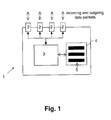
- Fig. 1 schematically depicts a network element 1 as employed according to an embodiment of the present invention.
- network element 1 may be a network switch or a network router.
- the illustrated network element 1 includes a total of four element ports 2 via which incoming/outgoing packets can be received/transmitted by the network element 1. Internally, the element ports 2 are connected to an element processor 3 that is in charge of the entire element control. In the network element 1, a "flow table" 4 is assumed that contains "flow entries" 5 (three of which are exemplarily indicated in Fig. 1 ) that decide how to forward packets that the network element 1 receives.
- a flow entry 5 generally defines a mapping between physical element ports, but can also involve virtual ports such as "all ports but the port via which the packet was received" or "queue i on port j".
- Target sets are used to characterize both a network element as a whole and individual element ports in terms of utilization and are derived from flow entries.
- the union of the two subsets in 1) and 2) is the "port target set" for element port P and together with the changes in this target set determines when an element port is in use and when an element port must be turned on or off.
- the port target set is nonempty, at least one element in the set (that is, a flow entry) points to port P either directly (at network element S ) or indirectly (at some adjacent network element T ) and the port might be in use for packet forwarding. If the port target set is empty, element port P is not the egress or ingress port for any packet and can be deactivated.
- the relevant changes in a port target set are, therefore, the creation of a port target set for an element port (or, the adding of the first element to an empty port target set) that indicates that an element port must be turned on, and the emptying of a port target set (or, the removal of the last element from a nonempty port target set), which indicates that an element port can be turned off.
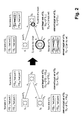
- FIG. 2 Both port target sets and element target sets are schematically illustrated in Fig. 2 .
- a number of flow entries are removed at network elements S 2 and S 3 .
- the port target sets of S 3 and the element target sets of both S 2 and S 3 change.
- the element target set of S 2 is now empty, that network element can be shut down.
- the port target set TS 35 has become empty, and element port P 5 can be shut down.
- the case where flow entries are added works analogously.
- the definition of element target sets and port target sets may also consider the possibility that these target sets can be constructed by cooperation also beyond the adjacent network elements of the considered network element (that is, to neighbors of neighbors of the network element in question).
- the definition of port target sets and element target sets can be influenced also by additional external triggers, e.g. in order to start up a switch even if no flow entries are pointing to it.
- the notion of port target sets and element target sets can also be applied to higher levels of aggregations, such as target sets that capture a network segment that is composed of several network elements.
- the first solution "centralized power control”
- a controller node performs all control actions on network elements.
- control actions are, at least partly, performed within the network by cooperation between network elements.
- the first solution does not require specific functionality of network elements.
- the second solution requires additional computing support in the network elements.
- Centralized power control leaves all control actions to the controller and works in a centralized way. That is, upon the relevant changes of port target sets or element target sets, the controller initiates the shut down and start up of the corresponding port and element, respectively.
- Switching on network elements can happen in in-band or out-of-band fashions.
- out-of-band case all network elements possess a direct link to the controller node and they can be switched on directly and in parallel.
- start-up messages are sent to network elements via the regular data links and are therefore subject to the same routing and power-savings mechanisms as regular packets. It can therefore happen that contacting certain network elements requires switching on other elements beforehand.
- the controller node therefore calculates a plan for sequentially switching on elements based on the power states of elements and element connectivity, in case direct reachability is not given.
- starting up a network element In contrast to the starting up of an element port, starting up a network element generally takes a significant amount of time. This means that a packet that has been intercepted by a network element may have to be forwarded via intermediary network elements that are not yet operational. The trivial solution is to simply drop the packet and all subsequent packets that match the same flow entry until all required network elements are operational. This solution is undesirable, since it may involve a large number of packets being dropped and especially for users in the Internet may result in suboptimal experience.
- a packet is buffered until all relevant network elements become available again.
- This solution is transparent in functional terms but only involves a delay in the response to the request that is being buffered. Since in most cases the buffered packet corresponds to an initial request of a client application (e.g. the request to start streaming a video), only a single delay is introduced until the flow is firmly established, which is often acceptable (and often also indistinguishable from other possible causes for delay) by a client.
- the delayed network element startup and packet buffering method works according to the following steps, illustrated in Fig. 4 :
- FIG. 4 shows the situation where network elements S2 and S3 are completing their startup procedure, with the following steps occurring:
- flow entry timeouts can further be distinguished into soft and hard timeouts, where the first depends on the most recent use time of the respective entry and the last is a firm timeout that occurs after a fixed period from the installation of the flow entry. In any case, expiration of an entry triggers re-calculation of both port and element target sets.
- the process of flow entry removal after a (soft or hard) timeout of a flow table entry has occurred is illustrated in Fig. 3 on the right side. In practice, such timeouts can be expected to occur much more frequently than the proactive removal of a flow table entry by the controller node.
- centralized power control proves to be disadvantageous in that it involves significant communication overhead between network elements and the controller node.
- a method in order to reduce the communication overhead, a method can be applied according to which the controller node duplicates, or mimics, network element state changes relevant to port and element target sets without interacting with the involved elements.
- the controller node knows about hard timeouts at network elements. It can use that information to remove flow entries from its local copy of network elements' flow tables at the end of the entries' lifetimes. Network elements do the same on their copy ensuring both copies to be equal Accordingly, there is no need to explicitly signal flow entry removal due to hard timeouts from network elements to the controller node. Soft timeouts do need to be signaled, but their forwarding can be optimized as described below.
- a soft timeout is a time interval dt soft-timeout that expires if a flow entry has not been used for dt soft-timeout . If a packet is forwarded at current time T current , hence, the next soft timeout is scheduled for T current + dt soft-timeout .
- clocked soft timeouts are used, where a soft timeout clock interval dt soft-timeout-cycle is introduced and soft timeouts are clocked accordingly. Then, a packet that is switched at T current leads to the scheduling of the next soft timeout for the corresponding flow table entry at T current + dt soft-timeout + dt soft-timeout-fill .
- Fig. 5 illustrates several examples of this type of synchronization. In particular, it is to be noted that the non-clocked soft timeouts of different flow entries do not have to be of the same length.
- soft timeouts and hard timeouts occur independently from one another.
- a soft timeout dt soft-timeout3 is clocked and synchronized with hard timeouts such that it coincides with a hard timeout. It is to be noted that it is not necessary to synchronize hard timeouts among one another, because they are traffic-independent and can be mimicked by the controller node.
- Centralized power control either without or with mimic function requires the interaction between network elements and the controller node.
- the controller node always needs to send explicit shut down messages to the network elements in order to shut them down.
- the management of port target sets and element target sets is distributed by embedding this function into the network elements themselves. Similar to the aggregation function applied in Section 2.2.2, embedding target set management requires additional computational support at the network elements (e.g. switches).
- the principal idea and approach is to distribute target set management and trigger the turning on and off of network elements accordingly.
- Adding new flow entries is initiated by a controller node as described in Section 2.1.1. Modification of power control with centralized coordination is required with respect to the approach according to which packets are buffered in a network element while network elements needed for forwarding the packet are starting up.
- the functionality performed by the controller node regarding packet buffering and element startup is moved to the first network element at which the packet was intercepted.
- these functions were split between controller node and network element.
- the first network element buffers the incoming packet and asks the controller to find an appropriate route through the network.
- the initial network element then contacts all network elements on the path, communicating routing table entries to them. Elements that are switched off are first turned on by exploiting the Wake-on-LAN capability.
- the initial element waits for incoming notifications about all the elements being operational and it then releases the buffered packet into the network as described in Section 2.1.2, so that it can be delivered to its final destination.
- Target sets are updated by the individual network elements according to the routing information received from the initial network element.
Landscapes
- Engineering & Computer Science (AREA)
- Computer Networks & Wireless Communication (AREA)
- Signal Processing (AREA)
- Data Exchanges In Wide-Area Networks (AREA)
- Communication Control (AREA)
Description
- The present invention relates to a method of supporting power control in a communication network, said network including a plurality of network elements that perform packet forwarding, wherein each network element includes one or more ports - element ports -.
- In order to reduce global CO2 emissions incurred by the operation of information and communication technology (ICT), energy management of ICT infrastructures has become one of society's key objectives. In particular, reducing the energy consumption of communication networks, e.g. data centers or core networks, which may be composed of a large number of network elements, such as network switches and network routers, has become an important partial objective within the ICT scope.
- On one hand, energy saving strategies deal with questions of how to forward traffic in such a way that the network elements are optimally utilized in terms of energy consumption. For example, increasing the traffic flow on a highly loaded network element is generally more suitable, since it will more likely lead to the situation where network elements that are only lightly loaded can be relieved of all traffic flow eventually. On the other hand, and usually subsequent to the calculations of the energy saving strategies, power control mechanisms act on the network elements by shutting them down and starting them up without impacting the network's functioning. Which network elements to shut down and which ones to start up is often decided separately from the energy saving strategies and requires a consistent analysis of the network state such that only those network elements are shut down that are definitely known to be not in use.
- This problem shows to be very difficult because communication networks are generally characterized by complex traffic flows and dynamic interactions between peers connected to the network. As a result, the network elements' state relevant for performing packet forwarding and routing decisions may change frequently. This leads to the particular situation that a network element cannot be shut down solely based on an analysis of its own state, but the state of adjacent network elements must also be considered. Additional complexity is introduced by the fact that power state transitions may incur a certain amount of time, and during the process of starting up, packets that cannot be forwarded via a transiting network element need to be handled in a suitable way.
- Apart from energy saving strategies that focus on the optimization of the utilization of network elements, e.g. the ones described in M. Baldi, Y. Ofek: "Time for a "Greener" Internet.", in Proceedings of the IEEE International Conference on Communications Workshops, 2009, in A. Cianfrani, "An Energy Saving Routing Algorithm for a Green OSPF Protocol", XP31677413, or in
WO 2011/124236 , state of the art related to power control does not provide an effective solution on how to decide consistently and uniformly which network elements must be turned on or off in exactly which situations. - On the one hand, relatively simple methods enable to shut down and start up individual network elements (e.g. described in the White Paper: "Wake on LAN Technology.", Lieberman Software Corporation, Rev 2 - June 1, 2006, or in White Paper: "Magic Packet Technology. Advanced Micro Devices.", Publication# 20213, Rev: A, Amendment/0. Issue Date: November 1995). More specifically,
US 4,677,566 andUS 4,635,195 provide a centralized power control logic system that maintains a consistent view of the power state of a set of connected network elements and allow to control the power state of each connected element by turning it on or off. These contributions do, however, not consider the larger network context each network element may be part of. In summary, the above mentioned approaches can be regarded as enabling technologies that may be used by the method proposed by the present invention. - On the other hand, some power management methods also consider interactions between processing elements of the same network element (e.g. described in
US 2004/0163000 A1 ) or a network element's wider context (e.g. described inUS 2009/0274070 A1 ), but do not define concrete methods that consistently perform power control of all the network elements in a communication network. More specifically,US 2004/0163000 A1 describes a state machine that is incorporated into the network processor of a network element (e.g. a SOHO router), which adapts the power consumption of multiple processing elements of that network processor depending on monitored utilization of each processing element and also based on interdependencies between processing elements of the same network processor.US 2009/0274070 A1 describes methods to optimize power management of end and network devices attached to a communication network. - It is therefore an object of the present invention to improve and further develop a method of the initially described type of supporting power control in a communication network in such a way that an optimized utilization of network elements becomes readily possible, while at the same time the overall energy savings in the communication network shall be highly effective.
- In accordance with the invention, the aforementioned object is accomplished by a method comprising the features of
claim 1. According to this claim, such a method is characterized in the steps of assigning a flow table to each of said network elements, wherein said flow table includes flow entries that specify via which element ports to forward packets the network element receives, deriving target sets from said flow tables, wherein a target set characterizes either a network element as a whole - element target set - or an individual element port - port target set - in terms of its utilization, and based on changes in the respective target sets, deciding on the enforcement of power states on said network elements and/or said element ports. - While intuitively, a freed network element can be turned off and when required must be turned on again, according to the invention it has been recognized that controlling a network element's power state in a uniform and consistent way often shows to be very difficult. This is because in networks where switching and routing is used to forward packets, a network element's state may change frequently and may also depend on the state of adjacent network elements. Furthermore, changing the power state of a network element may involve temporal overhead that needs to be considered, and care must be taken to handle data packets in an appropriate way while network elements are in the process of starting up.
- According to the present invention the power state of network elements in a communication network is controlled based on the notion of so-called target sets and their management. Target sets characterize each network element and its individual element ports by a set based on which it is possible to quickly decide whether the network element and each of the element ports must be turned on or off. As a result, the method according to the present invention provides a comprehensive practical basis (target sets and their management) to characterize whether a network element and also an element's port must be turned on or off with minor impact (only delays) on packet forwarding. In contrast to prior art approaches, the present invention considers multiple interconnected network elements on the granularity of both the elements and their individual ports. This means that a network-wide power management approach is taken by considering a wider context of each network element that is beyond the individual element's view.
- Transitional delays between power states (e.g. startup and shutdown durations) can be parameterized arbitrarily, for instance, individually for every single network element, which does not influence the functioning of the methods. Moreover, the method according to the present invention is applicable to any kind of energy model that may be used for a network element, for instance, elements where the power consumption of individual ports is negligible, in which case the target set of the complete network element can be used to control only the complete network element.
- Target sets, as defined by the present invention, are used to characterize both a network element as a whole and individual element ports in terms of their utilization, and they are derived from flow entries. According to a specific embodiment the target set of a single element port P of a network element S may be defined, informally, as the union of the following two subsets of flow entries:
- 1) All flow entries of network element S that have a forwarding rule whose egress port points to element port P. That egress port can be either the concrete port number P or an aggregation that includes port P, such as "all egress ports" or "all ports but the port via which the packet was received".
- 2) All flow entries of network element T, which is connected to network element S's port P via T's port Q, each flow entry having as egress port Q or an aggregation that includes port Q, such as "all egress ports" or "all ports but the port via which the packet was received".
- The union of the two subsets in 1) and 2) may then be defined to constitute the "port target set" for element port P and together with the changes in this target set determines when an element port is in use and when an element port can be turned on or off.
- In analogy to the port target set, extending the above concept to a whole network element, all individual port target sets of element ports P1 , P2, ..., Pn of a network element S may be unified in an "element target set" for the whole network element S.
- Based on the definition of target sets as describe above it may be provided that an element port is deactivated in case the corresponding port target set becomes empty and/or that a network element is deactivated in case the corresponding element target set becomes empty. In other words, if an element target set is nonempty, the associated network element must remain operational, otherwise, it can be turned off because the network element does not have any flow entries pointing to it (neither from the network element itself, nor from any other network element that is connected to it).
- According to a specific embodiment a centralized power control may be provided that, upon relevant changes of a port target set and/or an element target set, initiates the activation/deactivation of the corresponding element port and/or network element. This means that a centralized power control approach leaves all control actions to a controller and works in a centralized way. That is, upon the relevant changes of port or element target sets, the controller initiates the shut down and start up of the corresponding element port and network element, respectively.
- In case of a centralized power control approach it may further be provided that the centralized power control calculates a routing path, identifies network elements on the routing path, and stores a local copy of the flow tables of each of the network elements. Moreover, the centralized power control may calculate changes in the flow tables that need to be applied to establish the routing path, and select those network elements and element ports for which the element target set and port target set, respectively, have become non-empty. After having done so, the centralized power control may contact each selected network element and element port to initiate start up. As a result, an efficient adding of flow entries is realized, which requires only those network elements that are actually involved in packet forwarding along the routing path to become activated.
- In contrast to the starting up of an element port, starting up a network element generally takes a significant amount of time. This means that a packet that has been intercepted by a network element may have to be forwarded via intermediary network elements that are not yet operational. The trivial solution is to simply drop the packet and all subsequent packets that match the same flow entry until all required network elements are operational. This solution is undesirable, since it may involve a large number of packets being dropped and especially for users in the Internet may result in suboptimal experience.
- In order to avoid excessive packet droppings, which would result in a declined user experience, it may be provided that a packet intercepted by a network element on its routing path towards a destination node is buffered by that network element until it receives a signaling message from the centralized power control indicating that all network elements of the routing path have become activated.
- As an alternative to a purely centralized power control, in which a centralized controlled node is in charge of the entire control including the respective signaling, a power control approach could be deployed according to which at least some of the functionality is embedded in the network elements. For instance, in such case it may be provided that a first network element at which a packet, which is to be transmitted within the network, is intercepted buffers that packet and asks the centralized controller to find an appropriate routing path through the network. In a next step the first network element may contact all network elements on the routing path, communicating routing table entries to them. After that, the first element may wait for incoming notifications about all network elements on the routing path being operational, and it may then release the buffered packet into the network. Element target sets and/or port target sets may be updated by the network elements on the routing path individually according to the routing information received from the first network element.
- The main benefits of embedded power control are twofold: First, it does not require replicating information about each network element's flow table at the controller node for the purpose of power control, but the network elements manage their state alone to accomplish power management. That is, the decentralized, embedded model allows autonomous power management without the involvement of an external party. Secondly, it takes advantage of the fact that timing out of flow entries is already a local action that is autonomously occurring in the network and suggests embedded handling in the first place. Hence, both reduction of the communication between network elements and controller node and the reduction of computations at the controller node can significantly improve overall management efficiency.
- The decentralized, embedded method can be deployed in existing networks without affecting its regular function. It is even possible to mix network elements supporting power management and those not supporting power management. By providing both centralized and embedded methods for power control, an application in many types of network infrastructures is possible, depending on the support in network elements. It is even possible to mix features of centralized and embedded methods, which would be appropriate in heterogeneous infrastructures. For instance, in a specific embodiment it may be provided that methods of centralized and embedded power control are combined into a hybrid method such that one network segment is controlled by the embedded methods, while another segment, which may not support the embedding of management functions, is controlled centrally.
- The removal of flow entries is of particular interest in the embedded case because a significant amount of messages to the controller node can be omitted. According to a preferred embodiment it may be provided that a network element, in case a flow entry is removed from its flow table, adjusts its port target set and element target set, determines the set of adjacent network elements whose target sets are affected by the removed flow entry, and signals to all affected adjacent elements the removed flow entry. Based on the received information, all network elements are enabled to adapt their own element target sets and port target sets autonomously and to initiate appropriate shut-down procedures, if possible.
- Generally, it may be provided that flow entries are removed from flow tables implicitly by the definition of flow entry timeouts. Alternatively, flow entries may be removed from flow tables upon explicit request from the centralized power control.
- In principle, the shutting down of affected element ports and network elements can be executed with immediate effect. For an element port, this makes sense virtually always, because any overhead involved in port shutdown (e.g. deactivation of those parts of the element's electronics that are responsible for packet transmission and reception) can be assumed to be negligible in modern network switches and network routers. Whenever the port is required again, it can also be started up virtually immediately. For a complete network element, this situation is different because overhead in both temporal and energy terms is significant. To economize the network element's state changes it may be provided that, in case of a network element deactivation, an explicit idling period is introduced that has to elapse before the network element's deactivation procedure is finally initiated. If any flow entry is created in the meantime that leads to the creation of an element target set of the considered network element, that idling period may be reset and the network element may be considered in use again. Realizing the idling timeout can be done at the controller node or within the respective network element, directly, if supported.
- In case a port or switch is to be switched off and there are still packets queued on that port or switch, a local policy about how to proceed is consulted. Packets could simply be dropped and the shut-down action could be enforced immediately.
- Alternatively, the port/switch could just be tagged for shut-down and will only be switched off when the respective queue(s) have been emptied. The advantage is that packet drop is avoided and the efficiency of the network is sustained.
- According to another embodiment, instead of buffering packets during delayed switch startup, it may be provided that the delay incurred by the starting up of a relevant network element is signaled back to the requester, which then repeats the request when the delay has elapsed.
- Purely centralized power control as described above bears the problem that it involves significant communication overhead between network elements and the controller node. The following example illustrates the possible magnitude of overhead: Assume a network with 1000 network elements, each possessing a fairly sized flow table that leads to 1 flow entry timeout per second. In the whole network, this leads to 1000 signaling messages that the controller node will receive so that it can re-determine target sets. This is a significant overhead that can easily result in a bottleneck, especially because it is unlikely that the timeouts occur evenly distributed, but likely highly accumulated during some periods.
- In order to improve this situation, according to another preferred embodiment, it may be provided that the centralized power control duplicates or mimics network element state changes relevant to element target sets and/or port target sets. The centralized power control, based on information about hard flow entry timeouts, may then remove flow entries from its local copy of network elements' flow tables at the end of the entries' lifetimes. Network elements do the same on their copy ensuring both copies to be equal. Accordingly, there is no need to explicitly signal flow entry removal due to hard timeouts from network elements to the controller node.
- On the other hand, soft timeouts do need to be signaled, but their forwarding can be optimized. The respective solution that will be described in the following exploits the fact that many relevant events are independent of network traffic and can be mimicked by the controller node without network interaction. It is based on an optimization of the occurrence of traffic-dependent events by synchronization both among one another and also with traffic-independent events. The relevant actions that may occur in conjunction with a flow entry are the following:
- Adding of flow entry by controller node: this action requires the explicit interaction between the controller node and the network element, but no additional signaling.
- Explicit removal of flow entry by controller node: again, explicit interaction is required for this action and no additional signaling. As stated previously, this action should occur rather rarely, otherwise, a bottleneck will form.
- Removal of flow entry by hard timeout: because a hard timeout is a fixed constant that is known to the controller node, the behavior of flow entry removal based on hard timeouts can easily be mimicked by the controller node. Therefore, no signaling is required for this traffic-independent action.
- Removal of flow table entry by soft timeout: in contrast to hard timeouts, soft timeouts are traffic-dependent because they are reinitialized with every packet that is forward according to the flow entry the timeout is associated with. Signaling is required, but can be optimized as described below.
- It is likely that soft timeouts dominate the types of timeouts, since they are the most reactive ones due to their dependency on traffic. However, due to their traffic-dependency, they cannot be mimicked easily at the controller node, for which the controller node would need to monitor traffic at every network element.
- With respect to an optimization of the signaling of soft timeouts to the controller node it may be provided that soft flow entry timeouts of different flow entries of a flow table are synchronized with each other by introducing a soft timeout clock cycle. Additionally, it may be provided that hard timeouts are synchronized with soft timeouts by making the hard timeout interval a multiple of the soft timeout clock cycle.
- Generally, each selected network element and element port may be contacted by a control message from the centralized controller node to initiate start up. In the situation where a network element is on and only an element port is to be started up, this can be achieved for example via SNMP (Simple Network Management Protocol). In the situation where a network element is currently turned off and requires startup, signaling can be achieved by using for example Wake-On-LAN technology via special packets. Therefore, each network element may be equipped with such Wake-on-LAN capabilities, preferable on each port (e.g. via a "magic" packet).
- According to a specific application scenario, the methods as describe above may be applied to network routers that make use of routing tables containing routing entries, which decide on how to forward data packets. In this embodiment, routing entries correspond to flow entries, and routing tables correspond to flow tables. Target sets and target set management is then performed based on the routing entries of network routers. Alternatively or additionally, the methods may be applied to network switches that make use of switching tables containing switching entries, which decide on how to forward data packets. In this embodiment, switching entries correspond to flow entries, and switching tables correspond to flow tables. Target sets and target set management is then performed based on the switching entries of network switches. The switches may be, for instance, OpenFlow switches, where flow tables and flow table entries are used to define and manage the target sets ofOpen Flow switches and their ports. In particular, it is possible to apply the proposed methods to networks that are composed of heterogeneous network elements, such as network routers and network switches. It is possible to extend the definition of target sets in such a way that it can capture both routing and switching information consistently, because the semantics of that information is similar.
- There are several ways how to design and further develop the teaching of the present invention in an advantageous way. To this end, it is to be referred to the patent claims subordinate to
patent claim 1 on the one hand and to the following explanation of preferred embodiments of the invention by way of example, illustrated by the figure on the other hand. In connection with the explanation of the preferred embodiments of the invention by the aid of the figure, generally preferred embodiments and further developments of the teaching will be explained. In the drawings: - Fig. 1
- is a schematic view of a network element as employed according to an embodiment of the present invention,
- Fig. 2
- is a schematic view generally illustrating the concept of element target sets and port target sets as employed according to an embodiment according to the present invention,
- Fig. 3
- is a schematic view illustrating the adding of flow entries (left) and the removal of flow entries (right) with a centralized power control according to an embodiment of the present invention,
- Fig. 4
- is a schematic view illustrating a delayed network element startup and packet buffering with a centralized power control according to an embodiment of the present invention,
- Fig. 5
- is a schematic view illustrating the synchronization between soft timeouts and hard timeouts of flow entries according to an embodiment of the present invention, and
- Fig. 6
- is a schematic view illustrating the timeout and removal of flow entries with an embedded power control according to an embodiment of the present invention.
- In the following descriptions, as already mentioned above, the general terms "network element" and "element port" are used to refer to any kind of network element that performs packet forwarding, for example, a network router or a network switch.
Fig. 1 schematically depicts anetwork element 1 as employed according to an embodiment of the present invention. For instance,network element 1 may be a network switch or a network router. - The illustrated
network element 1 includes a total of fourelement ports 2 via which incoming/outgoing packets can be received/transmitted by thenetwork element 1. Internally, theelement ports 2 are connected to anelement processor 3 that is in charge of the entire element control. In thenetwork element 1, a "flow table" 4 is assumed that contains "flow entries" 5 (three of which are exemplarily indicated inFig. 1 ) that decide how to forward packets that thenetwork element 1 receives. Aflow entry 5 generally defines a mapping between physical element ports, but can also involve virtual ports such as "all ports but the port via which the packet was received" or "queue i on port j". - An important prerequisite to the definition of power control algorithms and the execution of power control actions is the knowledge about whether and when a specific network element can be turned off without compromising network functions. For example, it is intuitively clear that a network element involved in forwarding packets that belong to a certain traffic flow cannot be turned off while doing so. On the other hand, a network element should be turned on just at the right time when it is required for packet forwarding, while taking into consideration the latency for the network element start-up process.
- In the following, the conditions are described under which a particular network element will be turned on and off based on the concept of target sets. Target sets are used to characterize both a network element as a whole and individual element ports in terms of utilization and are derived from flow entries. Consider the target set of a single element port P of a network element S first, which is defined, informally, as the union of the following two subsets of flow entries:
- 1) All flow entries of network element S that have a forwarding rule whose egress port points to element port P. That egress port can be either the concrete port number P or an aggregation that includes port P, such as "all egress ports" or "all ports but the port via which the packet was received".
- 2) All flow entries of network element T, which is connected to network element S's port P via T's port Q, each flow entry having as egress port Q or an aggregation that includes port Q, such as "all egress ports" or "all ports but the port via which the packet was received".
- The union of the two subsets in 1) and 2) is the "port target set" for element port P and together with the changes in this target set determines when an element port is in use and when an element port must be turned on or off. When the port target set is nonempty, at least one element in the set (that is, a flow entry) points to port P either directly (at network element S) or indirectly (at some adjacent network element T) and the port might be in use for packet forwarding. If the port target set is empty, element port P is not the egress or ingress port for any packet and can be deactivated. The relevant changes in a port target set are, therefore, the creation of a port target set for an element port (or, the adding of the first element to an empty port target set) that indicates that an element port must be turned on, and the emptying of a port target set (or, the removal of the last element from a nonempty port target set), which indicates that an element port can be turned off.
- The previously described scheme holds for single element ports of a network element and can be extended to the whole network element as follows. For that, all individual port target sets of element ports P1 , P2 , ..., Pn of a network element S are unified in an "element target set" for the whole network element S. In analogy to the port target set, if the element target set is nonempty, the network element must remain operational, otherwise, it can be turned off because the network element does not have any flow entries pointing to it (neither from the network element itself, nor from any other network element that is connected to it).
- Both port target sets and element target sets are schematically illustrated in
Fig. 2 . InFig. 2 , a number of flow entries are removed at network elements S2 and S3 . As a result, the port target sets of S3 and the element target sets of both S2 and S3 change. Because the element target set of S2 is now empty, that network element can be shut down. For network element S3, only the port target set TS35 has become empty, and element port P5 can be shut down. The case where flow entries are added works analogously. - According to an even more sophisticated embodiment, the definition of element target sets and port target sets may also consider the possibility that these target sets can be constructed by cooperation also beyond the adjacent network elements of the considered network element (that is, to neighbors of neighbors of the network element in question). In another embodiment, the definition of port target sets and element target sets can be influenced also by additional external triggers, e.g. in order to start up a switch even if no flow entries are pointing to it. In still another embodiment, the notion of port target sets and element target sets can also be applied to higher levels of aggregations, such as target sets that capture a network segment that is composed of several network elements.
- In the following, two methods for power control based on port and element target sets according to the definition described above will be explained in some more detail. The first solution, "centralized power control", assumes that a controller node performs all control actions on network elements. In the second solution, "embedded power control", control actions are, at least partly, performed within the network by cooperation between network elements. The first solution does not require specific functionality of network elements. The second solution requires additional computing support in the network elements.
- Centralized power control leaves all control actions to the controller and works in a centralized way. That is, upon the relevant changes of port target sets or element target sets, the controller initiates the shut down and start up of the corresponding port and element, respectively.
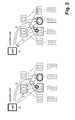
- Adding of flow entries in connection with a centralized power control is illustrated in the left part of
Fig. 3 . According to the illustrated embodiment the following sequence of steps will be executed: - 1) The controller node calculates a new path through a network which applies to a stream of packets (a "flow"). The network elements on that path are identified.
- 2) The controller node stores a local copy of each network element's flow table and calculates the changes that need to be applied in order to establish the previously selected route through the network. It applies the calculated changes to the local copy of the flow table and then recalculates both port and element target sets that might be affected according to the target set definitions in
Section 2. The set of network elements that are affected are the ones that were just augmented by an additional flow entry, and those adjacent network elements that are pointed to by any network element's new flow entry. Based on the performed calculations, those network elements and element ports are selected for which the element target set and port target set, respectively, have now become non-empty. - 3) Each selected network element and element port is contacted by a control message from the controller node to initiate start up. In the situation where a network element is on and only an element port is to be started up, this can be achieved for example via SNMP. In the situation where a network element is currently turned off and requires startup, signaling can be achieved by using for example Wake-On-LAN technology via special packets (as described, for instance, in the two White Papers named in the introduction).
- 4) As soon as all network elements and element ports are started up, the controller node adds flow entries for the new flow at the subset of network elements that are involved in forwarding packets via that flow.
- Switching on network elements can happen in in-band or out-of-band fashions. In the out-of-band case all network elements possess a direct link to the controller node and they can be switched on directly and in parallel. In the in-band case start-up messages are sent to network elements via the regular data links and are therefore subject to the same routing and power-savings mechanisms as regular packets. It can therefore happen that contacting certain network elements requires switching on other elements beforehand. The controller node therefore calculates a plan for sequentially switching on elements based on the power states of elements and element connectivity, in case direct reachability is not given.
- In contrast to the starting up of an element port, starting up a network element generally takes a significant amount of time. This means that a packet that has been intercepted by a network element may have to be forwarded via intermediary network elements that are not yet operational. The trivial solution is to simply drop the packet and all subsequent packets that match the same flow entry until all required network elements are operational. This solution is undesirable, since it may involve a large number of packets being dropped and especially for users in the Internet may result in suboptimal experience.
- Instead, according to the embodiment described in the following in connection with
Fig. 4 , a packet is buffered until all relevant network elements become available again. This solution is transparent in functional terms but only involves a delay in the response to the request that is being buffered. Since in most cases the buffered packet corresponds to an initial request of a client application (e.g. the request to start streaming a video), only a single delay is introduced until the flow is firmly established, which is often acceptable (and often also indistinguishable from other possible causes for delay) by a client. - The delayed network element startup and packet buffering method works according to the following steps, illustrated in
Fig. 4 : - 1) The packet is intercepted by the controller node and processed in such a way that a destination end node that is connected to the network is selected and also a network path to that end node. For that, any load balancing and path calculation engines can be used, e.g. the ones described in
PCT/EP 2010/002219 Fig. 4 , the selected path is via network elements S1, S2, and S3. - 2) From the flow entries to be created, those are enforced that belong to network elements that are currently operational (on). Network elements that are currently off cannot be communicated with for flow entry creation. In
Fig. 4 , only S1 is operational. - 3) To the network element at which the packet was intercepted, the controller node indicates to buffer the packet until further notice from the controller node. The network element in turn puts the relevant packet in a local buffer.
- 4) For all network elements that are currently off, the controller node signals to these elements that they need to turn on. This can be accomplished, for instance, by Wake-on-LAN technology as noted before. Those network elements that are already in the process of starting up (which is possible due to a previous flow creation process) may be omitted.
- 5) During the time the affected network elements are starting up, the controller also holds a record with a suitable packet ID (e.g. the packet's sequence number) and the network element that buffers the packet. Furthermore, IDs (e.g. IP addresses) of the network elements that are pending startup are stored in that record as well.
- The right side of
Fig. 4 shows the situation where network elements S2 and S3 are completing their startup procedure, with the following steps occurring: - 6) At t1, network element S2 completes its startup process and becomes operational, which it signals to the controller node.
- 7) The controller node removes S2 from the set of network elements pending startup for the buffered packet entry and transmits the flow entry to be created to S2.
- 8) At t2, network element S3 becomes operational and signals to the controller node.
- 9) The controller node removes S3 from the set of network elements pending startup and transmits S3's flow entry.
- 10) At this time, the controller node detects that the set of pending network elements is empty, indicating that the path of the flow is complete.
- 11) The controller node now sends a forwarding indication to indicate to the buffering network element that the packet currently buffered can be released into the network.
- 12) At this time, all flow entries exist in network elements S1, S2, and S3 and the packet can be forwarded to its destination.
- The removal of flow entries can occur either implicitly by flow entry timeouts or by explicit request of the controller node. Flow entry timeouts can further be distinguished into soft and hard timeouts, where the first depends on the most recent use time of the respective entry and the last is a firm timeout that occurs after a fixed period from the installation of the flow entry. In any case, expiration of an entry triggers re-calculation of both port and element target sets. The process of flow entry removal after a (soft or hard) timeout of a flow table entry has occurred is illustrated in
Fig. 3 on the right side. In practice, such timeouts can be expected to occur much more frequently than the proactive removal of a flow table entry by the controller node. - 1) A hard timeout occurs at a network element and the flow entry is removed.
- 2) Entry removal is signaled to the controller node, which updates the change in its local storage. If the controller node removes an entry proactively, this step is not applicable. The controller node then recalculates both port and element target sets that might be affected by the removed flow entry. Based on the performed calculations, those elements and ports are selected for which the element and port target set now contain no more entries.
- 3) In the most rigorous case, each selected network element and element port is contacted by a control message (e.g. via SNMP) from the controller node to initiate shut down.
- 4) Network elements and element ports are powered down. While a port's powering down becomes effective instantaneously, the powering down of a network element may be a transition involving time, depending on whether the network element requires consistent shutdown or can be turned off immediately (the former case being the more likely one).
- As already mentioned above, centralized power control proves to be disadvantageous in that it involves significant communication overhead between network elements and the controller node.
- According to an embodiment of the present invention, in order to reduce the communication overhead, a method can be applied according to which the controller node duplicates, or mimics, network element state changes relevant to port and element target sets without interacting with the involved elements. The controller node knows about hard timeouts at network elements. It can use that information to remove flow entries from its local copy of network elements' flow tables at the end of the entries' lifetimes. Network elements do the same on their copy ensuring both copies to be equal Accordingly, there is no need to explicitly signal flow entry removal due to hard timeouts from network elements to the controller node. Soft timeouts do need to be signaled, but their forwarding can be optimized as described below. The key ideas of this part of the invention are
- 1) to exploit the fact that many relevant events are independent of network traffic and can be mimicked by the controller node without network interaction, and
- 2) to optimize the occurrence of traffic-dependent events by synchronization both among one another and also with traffic-independent events.
- In the usual approach, a soft timeout is a time interval dtsoft-timeout that expires if a flow entry has not been used for dtsoft-timeout. If a packet is forwarded at current time Tcurrent, hence, the next soft timeout is scheduled for Tcurrent + dtsoft-timeout.
- According to an embodiment of the present invention clocked soft timeouts are used, where a soft timeout clock interval dtsoft-timeout-cycle is introduced and soft timeouts are clocked accordingly. Then, a packet that is switched at Tcurrent leads to the scheduling of the next soft timeout for the corresponding flow table entry at Tcurrent + dtsoft-timeout + dtsoft-timeout-fill.
Fig. 5 illustrates several examples of this type of synchronization. In particular, it is to be noted that the non-clocked soft timeouts of different flow entries do not have to be of the same length. - All flow table entries that are expiring at the same time n * dtsoft-timeout-cycle are signaled to the controller together in a single message. The batching of the entry removal notifications reduces the communications traffic between the network elements and their controllers as multiple individual messages are now signaled together in a single message.
- In the usual approach, soft timeouts and hard timeouts occur independently from one another. According to a specific embodiment of the present invention a further optimization of the occurrence of soft timeouts is achieved by synchronizing them in a way that is more likely to coincide with the occurrence of hard timeouts. This can be supported by making the hard timeout dthard-timeout interval a multiple of the soft timeout clock cycle, that is, dthard-timeout = n • dtsoft-timeout-cycle.
- Using this kind of synchronization leads to soft timeouts that coincide with hard timeouts that need not be signaled separately to the controller node since the hard timeout is known to the controller and correctly reflected in the controller's flow table copies.
- In
Fig. 5 an example is shown where a soft timeout dtsoft-timeout3 is clocked and synchronized with hard timeouts such that it coincides with a hard timeout. It is to be noted that it is not necessary to synchronize hard timeouts among one another, because they are traffic-independent and can be mimicked by the controller node. - The following example uses values of the previous example and illustrates the effectiveness of timeout synchronization. It is assumed dthard-timeout = 60 s, dtsoft-timeout = 7 s, dtsoft-timeout-cycle = 10 s. As before, it is further assumed that 1000 soft timeouts occur every second in the whole network. Synchronization leads to 167 timeouts occurring in sync in the mean, and in particular, to 167 timeouts that are in sync with the hard timeout. Assuming that the events generated by timeouts can be fully aggregated in the network prior to their signaling to the controller node, only 5 aggregate messages need to be sent to the controller node. This approach therefore requires the network to support such aggregation functionality in order to exploit the full potential of the synchronization method.
- Centralized power control either without or with mimic function requires the interaction between network elements and the controller node. In particular, the controller node always needs to send explicit shut down messages to the network elements in order to shut them down.
- According to an embodiment of the present invention the management of port target sets and element target sets is distributed by embedding this function into the network elements themselves. Similar to the aggregation function applied in Section 2.2.2, embedding target set management requires additional computational support at the network elements (e.g. switches).
- In the following, three basic assumptions are made about the enabling technologies required to allow the implementation of embedded power control:
- Each network element possesses Wake-on-LAN capabilities on each port (e.g. via a "magic" packet), as has been assumed previously.
- Each network element possesses local computation and storage capabilities to embed a limited set of management functionality.
- Each network element can communicate with its neighboring network elements via a simple management protocol for signaling purposes.
- The principal idea and approach is to distribute target set management and trigger the turning on and off of network elements accordingly.
- Adding new flow entries is initiated by a controller node as described in Section 2.1.1. Modification of power control with centralized coordination is required with respect to the approach according to which packets are buffered in a network element while network elements needed for forwarding the packet are starting up.
- According to an embodiment of the present invention the functionality performed by the controller node regarding packet buffering and element startup is moved to the first network element at which the packet was intercepted. In the embodiments described previously these functions were split between controller node and network element.
- As before, the first network element buffers the incoming packet and asks the controller to find an appropriate route through the network. The initial network element then contacts all network elements on the path, communicating routing table entries to them. Elements that are switched off are first turned on by exploiting the Wake-on-LAN capability. The initial element waits for incoming notifications about all the elements being operational and it then releases the buffered packet into the network as described in Section 2.1.2, so that it can be delivered to its final destination. Target sets are updated by the individual network elements according to the routing information received from the initial network element.
- The removal of flow entries is of particular interest in the embedded case because a significant amount of messages to the controller node can be omitted. The removal of a flow entry that occurs due to a hard or soft timeout is shown in detail in
Fig. 6 , with the following steps being executed: - 1) A timeout occurs at a network element and the flow entry is removed.
- 2) The network element adjusts the local port and switch target set based on the removed flow entry. The network element then determines the set of adjacent network elements whose target sets are affected by the removed flow entry. This is done by checking the egress port of the removed entry. If it is a single port, a single adjacent network element is affected. In the case of an aggregated port, multiple adjacent elements may be affected.
- 3) The network element signals to all affected adjacent elements the removed flow entry.
- 4) All network elements adapt their own port and element target sets autonomously based on the received information.
- 5) At this point, all network elements whose target sets have changed have also executed these changes and can autonomously determine whether one or more ports or the network element as a whole can be shut down. For each emptied port target set, the corresponding port is shut down immediately. For each emptied element target set, the network element enters idling state and is scheduled for shutdown after a fixed idling period. When the idling period elapses, the network element finally shuts down.
- Finally, it is to be noted that any part of described functions may be implemented in software, hardware, or both. This holds specifically for functions that are located at network elements.
- Many modifications and other embodiments of the invention set forth herein will come to mind the one skilled in the art to which the invention pertains having the benefit of the teachings presented in the foregoing description and the associated drawings. Therefore, it is to be understood that the invention is not to be limited to the specific embodiments disclosed and that modifications and other embodiments are intended to be included within the scope of the appended claims. Although specific terms are employed herein, they are used in a generic and descriptive sense only and not for purposes of limitation.
Claims (15)
- Method of supporting power control in a communication network, said network including a plurality of network elements (1) that perform packet forwarding, wherein each network element (1) includes one or more ports - element ports (2)-,
characterized in the steps ofassigning a flow table (4) to each of said network elements (1), wherein said flow table (4) includes flow entries (5) that specify via which element ports (2) to forward packets the network element (1) receives,deriving target sets from said flow tables (4), wherein a target set, which characterizes either a network element (1) as a whole - element target set - or an individual element port (2) - port target set - in terms of the utilization of said network element (1) or said element port (2) in that it is involved in packet forwarding, includes all flow entries of said network element (1) and of network elements connected thereto, which point to said network element (1) or to said element port (2), respectively, andbased on changes in the respective target sets, deciding on the enforcement of power states on said network elements (1) and/or said element ports (2). - Method according to claim 1, wherein the target set of an element port (2) of a network element (1) - port target set - includes all flow entries (5) of said network element (1) that have element port (2) as egress port together with all flow entries of other network elements that are connected to said network element's (1) element port (2) via an element port being specified as egress port in said flow entries (5).
- Method according to claim 1 or 2, wherein the target set of a network element (1) - element target set - includes the flow entries (5) of all element ports (2) of said network element (1).
- Method according to any of claims 1 to 3, wherein an element port (2) is deactivated in case the corresponding port target set becomes empty and/or wherein a network element (1) is deactivated in case the corresponding element target set becomes empty.
- Method according to any of claims 1 to 4, wherein a centralized power control is provided that, upon relevant changes of a port target set and/or an element target set, initiates the activation/deactivation of the corresponding element port (2) and/or network element (1).
- Method according to claim 5, wherein said centralized power control calculates a routing path, identifies network elements (1) on said routing path, and stores a local copy of the flow tables (5) of each of said network elements (1).
- Method according to claim 6, wherein said centralized power control calculates changes in said flow tables (5) that need to be applied to establish said routing path, and selects those network elements (1) and element ports (2) for which the element target set and port target set, respectively, have become non-em pty,
wherein said centralized power control may contact each selected network element (1) and element port (2) to initiate start up. - Method according to any of claims 5 to 7, wherein a packet intercepted by a network element (1) on its routing path towards a destination node is buffered by said network element (1) until it receives a signaling message from said centralized power control indicating that all network elements (1) of said routing path are activated.
- Method according to any of claims 5 to 7, wherein a first network element (1) at which a packet, which is to be transmitted within said network, is intercepted buffers said packet and asks said centralized controller to find an appropriate routing path through said network.
- Method according to claim 9, wherein said first network element (1) contacts all network elements (1) on said routing path, communicating routing table entries to them, and/or
wherein said first element (1) waits for incoming notifications about all network elements (1) on said routing path being operational and it then releases said buffered packet into said network, and/or
wherein element target sets and/or port target sets are updated by said network elements (1) on said routing path individually according to the routing information received from said first network element (1). - Method according to any of claims 1 to 10, wherein a network element (1), in case a flow entry (5) is removed from its flow table (4), adjusts its port target set and element target set, determines the set of adjacent network elements whose target sets are affected by said removed flow entry (5), and signals to all affected adjacent elements the removed flow entry (5), and/or
wherein flow entries (5) are removed from flow tables (4) by the definition of flow entry timeouts or upon explicit request from said centralized power control. - Method according to any of claims 1 to 11, wherein, in case of a network element (1) deactivation, an idling period is introduced that has to elapse before said network element' s (1) deactivation procedure is finally initiated,
wherein said idling period may be reset in case a flow entry (5) is created in the meantime that results in the creation of an element target set for said network element (1), and/or
wherein said idling period may be controlled by said centralized power control or within the respective network element (1) directly. - Method according to any of claims 5 to 12, wherein said centralized power control duplicates or mimics network element (1) state changes relevant to element target sets and/or port target sets,
wherein said centralized power control, based on information about hard flow entry timeouts, may remove flow entries (5) from its local copy of network elements' (1) flow tables (4). - Method according to any of claims 1 to 13, wherein soft flow entry timeouts of different flow entries (5) of a flow table (4) are synchronized with each other by introducing a soft timeout clock cycle, and/or
wherein hard timeouts are synchronized with soft timeouts by making the hard timeout interval a multiple of said soft timeout clock cycle. - Method according to any of claims 1 to14, wherein said network elements (1) are equipped with Wake-on-LAN capabilities, and/or
wherein said network elements (1) are network routers/switches that make use of routing/switching tables containing routing/switching entries.
Applications Claiming Priority (1)
| Application Number | Priority Date | Filing Date | Title |
|---|---|---|---|
| PCT/EP2010/004185 WO2012003847A1 (en) | 2010-07-08 | 2010-07-08 | Method of supporting power control in a communication network |
Publications (2)
| Publication Number | Publication Date |
|---|---|
| EP2452250A1 EP2452250A1 (en) | 2012-05-16 |
| EP2452250B1 true EP2452250B1 (en) | 2015-09-09 |
Family
ID=43640099
Family Applications (1)
| Application Number | Title | Priority Date | Filing Date |
|---|---|---|---|
| EP10737761.6A Not-in-force EP2452250B1 (en) | 2010-07-08 | 2010-07-08 | Method of supporting power control in a communication network |
Country Status (4)
| Country | Link |
|---|---|
| US (1) | US9106580B2 (en) |
| EP (1) | EP2452250B1 (en) |
| JP (1) | JP5242859B2 (en) |
| WO (1) | WO2012003847A1 (en) |
Families Citing this family (10)
| Publication number | Priority date | Publication date | Assignee | Title |
|---|---|---|---|---|
| US8824437B2 (en) * | 2011-03-02 | 2014-09-02 | Ricoh Company, Ltd. | Wireless communications device, electronic apparatus, and methods for determining and updating access point |
| WO2014021875A1 (en) * | 2012-07-31 | 2014-02-06 | Hewlett-Packard Development Company, L.P. | Power efficient network with network controller |
| TWI469569B (en) * | 2012-12-20 | 2015-01-11 | Hon Hai Prec Ind Co Ltd | Network Switch |
| US8761181B1 (en) * | 2013-04-19 | 2014-06-24 | Cubic Corporation | Packet sequence number tracking for duplicate packet detection |
| EP2996292B1 (en) | 2013-06-14 | 2020-08-05 | Huawei Technologies Co., Ltd. | Method for processing message and forwarder |
| WO2015044718A1 (en) * | 2013-09-27 | 2015-04-02 | Freescale Semiconductor, Inc. | A selectively powered layered network and a method thereof |
| CN107077343B (en) * | 2014-10-27 | 2021-04-23 | 惠普发展公司有限责任合伙企业 | Ignore input in Wake-on-LAN boot |
| WO2016097028A1 (en) * | 2014-12-16 | 2016-06-23 | Technische Universität Dresden | Method and assembly for information exchange in networks |
| CN106209390B (en) * | 2016-06-30 | 2021-04-13 | 武汉大学深圳研究院 | Network equipment management and energy-saving method, resource management device and routing energy-saving device thereof |
| CN110447013A (en) * | 2018-01-16 | 2019-11-12 | 深圳市汇顶科技股份有限公司 | Timer implementation method and device |
Family Cites Families (16)
| Publication number | Priority date | Publication date | Assignee | Title |
|---|---|---|---|---|
| US4635195A (en) | 1984-09-25 | 1987-01-06 | Burroughs Corporation | Power control network using reliable communications protocol |
| US4677566A (en) | 1984-10-18 | 1987-06-30 | Burroughs Corporation | Power control network for multiple digital modules |
| US8351339B2 (en) | 2002-04-25 | 2013-01-08 | Samsung Electronics Co., Ltd. | Method for bluetooth on-demand routing and network formation, and communication method in bluetooth group ad hoc network |
| US7337334B2 (en) | 2003-02-14 | 2008-02-26 | International Business Machines Corporation | Network processor power management |
| US7535841B1 (en) * | 2003-05-14 | 2009-05-19 | Nortel Networks Limited | Flow-rate-regulated burst switches |
| US7701858B2 (en) * | 2003-07-17 | 2010-04-20 | Sensicast Systems | Method and apparatus for wireless communication in a mesh network |
| JP2009086697A (en) * | 2006-01-18 | 2009-04-23 | Osaka Univ | Wireless sensor network and information transmission method thereof |
| US8098658B1 (en) * | 2006-08-01 | 2012-01-17 | Hewett-Packard Development Company, L.P. | Power-based networking resource allocation |
| JP4977534B2 (en) * | 2007-06-07 | 2012-07-18 | 株式会社日立製作所 | Sensor network system and sensor node |
| US20090003229A1 (en) * | 2007-06-30 | 2009-01-01 | Kai Siang Loh | Adaptive Bandwidth Management Systems And Methods |
| US8488500B2 (en) | 2008-05-02 | 2013-07-16 | Dhaani Systems | Power management of networked devices |
| US8166147B2 (en) * | 2008-10-28 | 2012-04-24 | Computer Associates Think, Inc. | Power usage reduction system and method |
| JP5166227B2 (en) | 2008-12-22 | 2013-03-21 | アラクサラネットワークス株式会社 | Packet transfer method, packet transfer apparatus, and packet transfer system |
| US8355328B2 (en) * | 2009-08-27 | 2013-01-15 | Broadcom Corporation | Dynamic load balancing |
| WO2011093901A1 (en) * | 2010-02-01 | 2011-08-04 | Hewlett-Packard Development Company, L.P. | Deep sleep mode management for a network switch |
| US8578191B2 (en) * | 2010-06-10 | 2013-11-05 | Juniper Networks, Inc. | Dynamic fabric plane allocation for power savings |
-
2010
- 2010-07-08 EP EP10737761.6A patent/EP2452250B1/en not_active Not-in-force
- 2010-07-08 JP JP2012546371A patent/JP5242859B2/en not_active Expired - Fee Related
- 2010-07-08 US US13/395,485 patent/US9106580B2/en active Active
- 2010-07-08 WO PCT/EP2010/004185 patent/WO2012003847A1/en not_active Ceased
Also Published As
| Publication number | Publication date |
|---|---|
| US9106580B2 (en) | 2015-08-11 |
| US20120170592A1 (en) | 2012-07-05 |
| EP2452250A1 (en) | 2012-05-16 |
| JP5242859B2 (en) | 2013-07-24 |
| JP2013519250A (en) | 2013-05-23 |
| WO2012003847A1 (en) | 2012-01-12 |
Similar Documents
| Publication | Publication Date | Title |
|---|---|---|
| US9106580B2 (en) | Method of supporting power control in a communication network | |
| Gupta et al. | A feasibility study for power management in LAN switches | |
| US7729361B2 (en) | Method and system for power-efficient adaptive link aggregation | |
| US8243594B1 (en) | Coordinated control of multiple parallel links or link aggregations | |
| CN102364892B (en) | Link aggregation control protocol (LACP) link switching and data transmission method and apparatus thereof | |
| US20250106768A1 (en) | Managing power states of aggregated links of a network device | |
| CN101309201B (en) | Route processing method, routing processor and router | |
| CN101984573A (en) | Method and system for distributed realization of LACP standard state machine | |
| CN101888307B (en) | The method and apparatus of port selection is realized for this locality | |
| EP2479924A1 (en) | Method and system for self-adapting dynamic power reduction mechanism for physical layer devices in packet data networks | |
| CN101483592B (en) | Method and apparatus for inhibiting bidirectional forwarding detection link oscillation | |
| US20110191568A1 (en) | Information processing apparatus and method of controlling the same | |
| CN112583510B (en) | A message forwarding method, device and system | |
| CN101888333A (en) | Method and apparatus for maintaining a port state table within a forwarding plane of a network element | |
| US8380860B2 (en) | Reducing carbon footprint and providing power savings in session initiated protocol conferencing | |
| Orgerie et al. | Energy-efficient bandwidth reservation for bulk data transfers in dedicated wired networks | |
| US20150169033A1 (en) | Systems and methods for power management in stackable switch | |
| US20100312909A1 (en) | Method and system for traffic based decisions for energy efficient networking | |
| Ho et al. | Green distributed routing protocol for sleep coordination in wired core networks | |
| CN100396014C (en) | Hot standby maintenance system and method for hot standby maintenance and failover | |
| US20150163126A1 (en) | Method for routing data traffic in a communication network | |
| Kamyabpour et al. | A hierarchy energy driven architecture for wireless sensor networks | |
| EP4620172A1 (en) | Devices and methods for network energy optimization | |
| CN118250213A (en) | Management method of aggregated link, communication node and communication system | |
| JP2014150350A (en) | Communication apparatus and communication apparatus control method |
Legal Events
| Date | Code | Title | Description |
|---|---|---|---|
| PUAI | Public reference made under article 153(3) epc to a published international application that has entered the european phase |
Free format text: ORIGINAL CODE: 0009012 |
|
| 17P | Request for examination filed |
Effective date: 20120208 |
|
| AK | Designated contracting states |
Kind code of ref document: A1 Designated state(s): AL AT BE BG CH CY CZ DE DK EE ES FI FR GB GR HR HU IE IS IT LI LT LU LV MC MK MT NL NO PL PT RO SE SI SK SM TR |
|
| DAX | Request for extension of the european patent (deleted) | ||
| 17Q | First examination report despatched |
Effective date: 20130923 |
|
| REG | Reference to a national code |
Ref country code: DE Ref legal event code: R079 Ref document number: 602010027396 Country of ref document: DE Free format text: PREVIOUS MAIN CLASS: G06F0001320000 Ipc: H04L0012120000 |
|
| GRAP | Despatch of communication of intention to grant a patent |
Free format text: ORIGINAL CODE: EPIDOSNIGR1 |
|
| RIC1 | Information provided on ipc code assigned before grant |
Ipc: H04W 52/02 20090101ALI20150610BHEP Ipc: H04L 12/24 20060101ALN20150610BHEP Ipc: H04L 12/717 20130101ALI20150610BHEP Ipc: H04L 12/12 20060101AFI20150610BHEP |
|
| INTG | Intention to grant announced |
Effective date: 20150623 |
|
| GRAS | Grant fee paid |
Free format text: ORIGINAL CODE: EPIDOSNIGR3 |
|
| GRAA | (expected) grant |
Free format text: ORIGINAL CODE: 0009210 |
|
| AK | Designated contracting states |
Kind code of ref document: B1 Designated state(s): AL AT BE BG CH CY CZ DE DK EE ES FI FR GB GR HR HU IE IS IT LI LT LU LV MC MK MT NL NO PL PT RO SE SI SK SM TR |
|
| RAP1 | Party data changed (applicant data changed or rights of an application transferred) |
Owner name: NEC CORPORATION |
|
| REG | Reference to a national code |
Ref country code: GB Ref legal event code: FG4D |
|
| REG | Reference to a national code |
Ref country code: AT Ref legal event code: REF Ref document number: 748891 Country of ref document: AT Kind code of ref document: T Effective date: 20150915 Ref country code: CH Ref legal event code: EP |
|
| REG | Reference to a national code |
Ref country code: IE Ref legal event code: FG4D |
|
| REG | Reference to a national code |
Ref country code: DE Ref legal event code: R096 Ref document number: 602010027396 Country of ref document: DE |
|
| REG | Reference to a national code |
Ref country code: NL Ref legal event code: MP Effective date: 20150909 |
|
| PG25 | Lapsed in a contracting state [announced via postgrant information from national office to epo] |
Ref country code: GR Free format text: LAPSE BECAUSE OF FAILURE TO SUBMIT A TRANSLATION OF THE DESCRIPTION OR TO PAY THE FEE WITHIN THE PRESCRIBED TIME-LIMIT Effective date: 20151210 Ref country code: NO Free format text: LAPSE BECAUSE OF FAILURE TO SUBMIT A TRANSLATION OF THE DESCRIPTION OR TO PAY THE FEE WITHIN THE PRESCRIBED TIME-LIMIT Effective date: 20151209 Ref country code: LT Free format text: LAPSE BECAUSE OF FAILURE TO SUBMIT A TRANSLATION OF THE DESCRIPTION OR TO PAY THE FEE WITHIN THE PRESCRIBED TIME-LIMIT Effective date: 20150909 Ref country code: LV Free format text: LAPSE BECAUSE OF FAILURE TO SUBMIT A TRANSLATION OF THE DESCRIPTION OR TO PAY THE FEE WITHIN THE PRESCRIBED TIME-LIMIT Effective date: 20150909 Ref country code: FI Free format text: LAPSE BECAUSE OF FAILURE TO SUBMIT A TRANSLATION OF THE DESCRIPTION OR TO PAY THE FEE WITHIN THE PRESCRIBED TIME-LIMIT Effective date: 20150909 |
|
| REG | Reference to a national code |
Ref country code: LT Ref legal event code: MG4D |
|
| REG | Reference to a national code |
Ref country code: AT Ref legal event code: MK05 Ref document number: 748891 Country of ref document: AT Kind code of ref document: T Effective date: 20150909 |
|
| PG25 | Lapsed in a contracting state [announced via postgrant information from national office to epo] |
Ref country code: HR Free format text: LAPSE BECAUSE OF FAILURE TO SUBMIT A TRANSLATION OF THE DESCRIPTION OR TO PAY THE FEE WITHIN THE PRESCRIBED TIME-LIMIT Effective date: 20150909 Ref country code: ES Free format text: LAPSE BECAUSE OF FAILURE TO SUBMIT A TRANSLATION OF THE DESCRIPTION OR TO PAY THE FEE WITHIN THE PRESCRIBED TIME-LIMIT Effective date: 20150909 Ref country code: SE Free format text: LAPSE BECAUSE OF FAILURE TO SUBMIT A TRANSLATION OF THE DESCRIPTION OR TO PAY THE FEE WITHIN THE PRESCRIBED TIME-LIMIT Effective date: 20150909 |
|
| PG25 | Lapsed in a contracting state [announced via postgrant information from national office to epo] |
Ref country code: NL Free format text: LAPSE BECAUSE OF FAILURE TO SUBMIT A TRANSLATION OF THE DESCRIPTION OR TO PAY THE FEE WITHIN THE PRESCRIBED TIME-LIMIT Effective date: 20150909 |
|
| PG25 | Lapsed in a contracting state [announced via postgrant information from national office to epo] |
Ref country code: IT Free format text: LAPSE BECAUSE OF FAILURE TO SUBMIT A TRANSLATION OF THE DESCRIPTION OR TO PAY THE FEE WITHIN THE PRESCRIBED TIME-LIMIT Effective date: 20150909 Ref country code: IS Free format text: LAPSE BECAUSE OF FAILURE TO SUBMIT A TRANSLATION OF THE DESCRIPTION OR TO PAY THE FEE WITHIN THE PRESCRIBED TIME-LIMIT Effective date: 20160109 Ref country code: SK Free format text: LAPSE BECAUSE OF FAILURE TO SUBMIT A TRANSLATION OF THE DESCRIPTION OR TO PAY THE FEE WITHIN THE PRESCRIBED TIME-LIMIT Effective date: 20150909 Ref country code: EE Free format text: LAPSE BECAUSE OF FAILURE TO SUBMIT A TRANSLATION OF THE DESCRIPTION OR TO PAY THE FEE WITHIN THE PRESCRIBED TIME-LIMIT Effective date: 20150909 Ref country code: CZ Free format text: LAPSE BECAUSE OF FAILURE TO SUBMIT A TRANSLATION OF THE DESCRIPTION OR TO PAY THE FEE WITHIN THE PRESCRIBED TIME-LIMIT Effective date: 20150909 |
|
| PG25 | Lapsed in a contracting state [announced via postgrant information from national office to epo] |
Ref country code: PT Free format text: LAPSE BECAUSE OF FAILURE TO SUBMIT A TRANSLATION OF THE DESCRIPTION OR TO PAY THE FEE WITHIN THE PRESCRIBED TIME-LIMIT Effective date: 20160111 Ref country code: AT Free format text: LAPSE BECAUSE OF FAILURE TO SUBMIT A TRANSLATION OF THE DESCRIPTION OR TO PAY THE FEE WITHIN THE PRESCRIBED TIME-LIMIT Effective date: 20150909 Ref country code: RO Free format text: LAPSE BECAUSE OF FAILURE TO SUBMIT A TRANSLATION OF THE DESCRIPTION OR TO PAY THE FEE WITHIN THE PRESCRIBED TIME-LIMIT Effective date: 20150909 Ref country code: PL Free format text: LAPSE BECAUSE OF FAILURE TO SUBMIT A TRANSLATION OF THE DESCRIPTION OR TO PAY THE FEE WITHIN THE PRESCRIBED TIME-LIMIT Effective date: 20150909 |
|
| REG | Reference to a national code |
Ref country code: DE Ref legal event code: R097 Ref document number: 602010027396 Country of ref document: DE |
|
| PLBE | No opposition filed within time limit |
Free format text: ORIGINAL CODE: 0009261 |
|
| STAA | Information on the status of an ep patent application or granted ep patent |
Free format text: STATUS: NO OPPOSITION FILED WITHIN TIME LIMIT |
|
| REG | Reference to a national code |
Ref country code: FR Ref legal event code: PLFP Year of fee payment: 7 |
|
| 26N | No opposition filed |
Effective date: 20160610 |
|
| PG25 | Lapsed in a contracting state [announced via postgrant information from national office to epo] |
Ref country code: SI Free format text: LAPSE BECAUSE OF FAILURE TO SUBMIT A TRANSLATION OF THE DESCRIPTION OR TO PAY THE FEE WITHIN THE PRESCRIBED TIME-LIMIT Effective date: 20150909 Ref country code: DK Free format text: LAPSE BECAUSE OF FAILURE TO SUBMIT A TRANSLATION OF THE DESCRIPTION OR TO PAY THE FEE WITHIN THE PRESCRIBED TIME-LIMIT Effective date: 20150909 |
|
| PG25 | Lapsed in a contracting state [announced via postgrant information from national office to epo] |
Ref country code: BE Free format text: LAPSE BECAUSE OF FAILURE TO SUBMIT A TRANSLATION OF THE DESCRIPTION OR TO PAY THE FEE WITHIN THE PRESCRIBED TIME-LIMIT Effective date: 20150909 |
|
| REG | Reference to a national code |
Ref country code: CH Ref legal event code: PL |
|
| PG25 | Lapsed in a contracting state [announced via postgrant information from national office to epo] |
Ref country code: MC Free format text: LAPSE BECAUSE OF FAILURE TO SUBMIT A TRANSLATION OF THE DESCRIPTION OR TO PAY THE FEE WITHIN THE PRESCRIBED TIME-LIMIT Effective date: 20150909 |
|
| PG25 | Lapsed in a contracting state [announced via postgrant information from national office to epo] |
Ref country code: LI Free format text: LAPSE BECAUSE OF NON-PAYMENT OF DUE FEES Effective date: 20160731 Ref country code: CH Free format text: LAPSE BECAUSE OF NON-PAYMENT OF DUE FEES Effective date: 20160731 |
|
| REG | Reference to a national code |
Ref country code: IE Ref legal event code: MM4A |
|
| REG | Reference to a national code |
Ref country code: FR Ref legal event code: PLFP Year of fee payment: 8 |
|
| PG25 | Lapsed in a contracting state [announced via postgrant information from national office to epo] |
Ref country code: IE Free format text: LAPSE BECAUSE OF NON-PAYMENT OF DUE FEES Effective date: 20160708 |
|
| PG25 | Lapsed in a contracting state [announced via postgrant information from national office to epo] |
Ref country code: LU Free format text: LAPSE BECAUSE OF NON-PAYMENT OF DUE FEES Effective date: 20160708 |
|
| PG25 | Lapsed in a contracting state [announced via postgrant information from national office to epo] |
Ref country code: HU Free format text: LAPSE BECAUSE OF FAILURE TO SUBMIT A TRANSLATION OF THE DESCRIPTION OR TO PAY THE FEE WITHIN THE PRESCRIBED TIME-LIMIT; INVALID AB INITIO Effective date: 20100708 Ref country code: SM Free format text: LAPSE BECAUSE OF FAILURE TO SUBMIT A TRANSLATION OF THE DESCRIPTION OR TO PAY THE FEE WITHIN THE PRESCRIBED TIME-LIMIT Effective date: 20150909 Ref country code: CY Free format text: LAPSE BECAUSE OF FAILURE TO SUBMIT A TRANSLATION OF THE DESCRIPTION OR TO PAY THE FEE WITHIN THE PRESCRIBED TIME-LIMIT Effective date: 20150909 |
|
| REG | Reference to a national code |
Ref country code: FR Ref legal event code: PLFP Year of fee payment: 9 |
|
| PG25 | Lapsed in a contracting state [announced via postgrant information from national office to epo] |
Ref country code: MK Free format text: LAPSE BECAUSE OF FAILURE TO SUBMIT A TRANSLATION OF THE DESCRIPTION OR TO PAY THE FEE WITHIN THE PRESCRIBED TIME-LIMIT Effective date: 20150909 Ref country code: TR Free format text: LAPSE BECAUSE OF FAILURE TO SUBMIT A TRANSLATION OF THE DESCRIPTION OR TO PAY THE FEE WITHIN THE PRESCRIBED TIME-LIMIT Effective date: 20150909 Ref country code: MT Free format text: LAPSE BECAUSE OF NON-PAYMENT OF DUE FEES Effective date: 20160731 |
|
| PG25 | Lapsed in a contracting state [announced via postgrant information from national office to epo] |
Ref country code: BG Free format text: LAPSE BECAUSE OF FAILURE TO SUBMIT A TRANSLATION OF THE DESCRIPTION OR TO PAY THE FEE WITHIN THE PRESCRIBED TIME-LIMIT Effective date: 20150909 |
|
| PG25 | Lapsed in a contracting state [announced via postgrant information from national office to epo] |
Ref country code: AL Free format text: LAPSE BECAUSE OF FAILURE TO SUBMIT A TRANSLATION OF THE DESCRIPTION OR TO PAY THE FEE WITHIN THE PRESCRIBED TIME-LIMIT Effective date: 20150909 |
|
| PGFP | Annual fee paid to national office [announced via postgrant information from national office to epo] |
Ref country code: FR Payment date: 20210728 Year of fee payment: 12 |
|
| PGFP | Annual fee paid to national office [announced via postgrant information from national office to epo] |
Ref country code: DE Payment date: 20210721 Year of fee payment: 12 Ref country code: GB Payment date: 20210722 Year of fee payment: 12 |
|
| REG | Reference to a national code |
Ref country code: DE Ref legal event code: R119 Ref document number: 602010027396 Country of ref document: DE |
|
| GBPC | Gb: european patent ceased through non-payment of renewal fee |
Effective date: 20220708 |
|
| PG25 | Lapsed in a contracting state [announced via postgrant information from national office to epo] |
Ref country code: FR Free format text: LAPSE BECAUSE OF NON-PAYMENT OF DUE FEES Effective date: 20220731 |
|
| PG25 | Lapsed in a contracting state [announced via postgrant information from national office to epo] |
Ref country code: GB Free format text: LAPSE BECAUSE OF NON-PAYMENT OF DUE FEES Effective date: 20220708 Ref country code: DE Free format text: LAPSE BECAUSE OF NON-PAYMENT OF DUE FEES Effective date: 20230201 |