EP2450936A1 - Microscope system, method for operating a charged-particle microscope - Google Patents
Microscope system, method for operating a charged-particle microscope Download PDFInfo
- Publication number
- EP2450936A1 EP2450936A1 EP10014245A EP10014245A EP2450936A1 EP 2450936 A1 EP2450936 A1 EP 2450936A1 EP 10014245 A EP10014245 A EP 10014245A EP 10014245 A EP10014245 A EP 10014245A EP 2450936 A1 EP2450936 A1 EP 2450936A1
- Authority
- EP
- European Patent Office
- Prior art keywords
- image
- region
- representation
- displayed
- microscope
- Prior art date
- Legal status (The legal status is an assumption and is not a legal conclusion. Google has not performed a legal analysis and makes no representation as to the accuracy of the status listed.)
- Granted
Links
Images



Classifications
-
- H—ELECTRICITY
- H01—ELECTRIC ELEMENTS
- H01J—ELECTRIC DISCHARGE TUBES OR DISCHARGE LAMPS
- H01J37/00—Discharge tubes with provision for introducing objects or material to be exposed to the discharge, e.g. for the purpose of examination or processing thereof
- H01J37/02—Details
- H01J37/22—Optical, image processing or photographic arrangements associated with the tube
- H01J37/222—Image processing arrangements associated with the tube
-
- G—PHYSICS
- G02—OPTICS
- G02B—OPTICAL ELEMENTS, SYSTEMS OR APPARATUS
- G02B21/00—Microscopes
- G02B21/36—Microscopes arranged for photographic purposes or projection purposes or digital imaging or video purposes including associated control and data processing arrangements
- G02B21/365—Control or image processing arrangements for digital or video microscopes
- G02B21/367—Control or image processing arrangements for digital or video microscopes providing an output produced by processing a plurality of individual source images, e.g. image tiling, montage, composite images, depth sectioning, image comparison
-
- H—ELECTRICITY
- H01—ELECTRIC ELEMENTS
- H01J—ELECTRIC DISCHARGE TUBES OR DISCHARGE LAMPS
- H01J37/00—Discharge tubes with provision for introducing objects or material to be exposed to the discharge, e.g. for the purpose of examination or processing thereof
- H01J37/02—Details
- H01J37/244—Detectors; Associated components or circuits therefor
-
- H—ELECTRICITY
- H01—ELECTRIC ELEMENTS
- H01J—ELECTRIC DISCHARGE TUBES OR DISCHARGE LAMPS
- H01J37/00—Discharge tubes with provision for introducing objects or material to be exposed to the discharge, e.g. for the purpose of examination or processing thereof
- H01J37/26—Electron or ion microscopes; Electron or ion diffraction tubes
-
- H—ELECTRICITY
- H01—ELECTRIC ELEMENTS
- H01J—ELECTRIC DISCHARGE TUBES OR DISCHARGE LAMPS
- H01J2237/00—Discharge tubes exposing object to beam, e.g. for analysis treatment, etching, imaging
- H01J2237/04—Means for controlling the discharge
- H01J2237/047—Changing particle velocity
-
- H—ELECTRICITY
- H01—ELECTRIC ELEMENTS
- H01J—ELECTRIC DISCHARGE TUBES OR DISCHARGE LAMPS
- H01J2237/00—Discharge tubes exposing object to beam, e.g. for analysis treatment, etching, imaging
- H01J2237/22—Treatment of data
-
- H—ELECTRICITY
- H01—ELECTRIC ELEMENTS
- H01J—ELECTRIC DISCHARGE TUBES OR DISCHARGE LAMPS
- H01J2237/00—Discharge tubes exposing object to beam, e.g. for analysis treatment, etching, imaging
- H01J2237/22—Treatment of data
- H01J2237/221—Image processing
-
- H—ELECTRICITY
- H01—ELECTRIC ELEMENTS
- H01J—ELECTRIC DISCHARGE TUBES OR DISCHARGE LAMPS
- H01J2237/00—Discharge tubes exposing object to beam, e.g. for analysis treatment, etching, imaging
- H01J2237/22—Treatment of data
- H01J2237/221—Image processing
- H01J2237/225—Displaying image using synthesised colours
-
- H—ELECTRICITY
- H01—ELECTRIC ELEMENTS
- H01J—ELECTRIC DISCHARGE TUBES OR DISCHARGE LAMPS
- H01J2237/00—Discharge tubes exposing object to beam, e.g. for analysis treatment, etching, imaging
- H01J2237/248—Components associated with the control of the tube
- H01J2237/2482—Optical means
-
- H—ELECTRICITY
- H01—ELECTRIC ELEMENTS
- H01J—ELECTRIC DISCHARGE TUBES OR DISCHARGE LAMPS
- H01J2237/00—Discharge tubes exposing object to beam, e.g. for analysis treatment, etching, imaging
- H01J2237/26—Electron or ion microscopes
- H01J2237/28—Scanning microscopes
Definitions
- the present invention relates generally to a method of operating a charged-particle microscope or a method of operating a combination of a charged-particle microscope with another microscope of a different type. More specifically, the invention is concerned with a method of operating a charged-particle microscope for managing a plurality of images which have been acquired at different microscope settings.
- SE detector secondary electron detector
- a backscattered electron detector (BSE detector) is typically placed close to the exit opening of the electron optical system to capture electrons, which are reflected or backscattered at acute angles from the object. Since the intensity of the BSE signal is strongly related to the atomic number (Z) of the object, BSE images can provide information about the distribution of chemical elements in the sample.
- BSE detectors are typically solid-state devices, often with multiple components. For example, by switching of two of the four quadrants of a 4-Quadrant BSE detector, some shadowing can be created resulting in a better topographical contrast.
- EDX detector energy-dispersive spectrometer
- a comprehensive study of an object with a scanning electron microscope may involve studying images of different magnifications which have been acquired by using different detectors from different locations on the specimen.
- a method of operating a charged-particle microscope comprising: recording a first image of a first region of an object using the charged-particle microscope in a first setting; recording a second image of a second region of the object using the charged-particle microscope in a second setting, wherein the second setting differs from the first setting with respect to at least one of a kinetic energy of primary charged particles used for imaging, a detector setting used for imaging, a beam current of the charged particles used for imaging and a pressure in a measuring chamber of the charged-particle microscope; recording a third image of a third region of the object using the charged-particle microscope, wherein the first and second regions are contained at least partially within the third region; displaying at least a portion of the third image; displaying a representation of the first image at least partly within the displayed third image, wherein the representation of the first image includes a first indicator which is indicative of the first setting; displaying a representation of the second image at least partly within the displayed third image, wherein the representation of the second image includes a second
- the method may be in particular a computer-implemented method.
- the charged-particle microscope may for example be an electron microscope or a helium ion microscope.
- the electron microscope may be a scanning electron microscope or a transmission electron microscope.
- the third image may be read from a storage medium.
- the storage medium may be part of a computer system or a data base. Additionally or alternatively, the third image may be read via a signal line from a light microscope or from the charged-particle microscope.
- the first region of the object may for example be a region of the object which is scanned by the charged-particle beam for acquiring the first image.
- the first and/or second setting may be defined as a set of operational parameters of the charged-particle microscope which are specified at a time when the first image is acquired.
- the first and/or second setting may comprise at least one of a kinetic energy of the electron beam, a detector setting used for imaging, a beam current of the charged particles used for imaging and a pressure in a measuring chamber.
- the detector setting may comprise at least one of the following: a type of a detector used for acquiring the image, a number of the detectors used for acquiring the image and a value of an operational parameter of the one or more detectors used for imaging.
- the measuring chamber may be a vacuum chamber. The pressure may be measured at the time when the image is acquired.
- the operational parameters of the one or more detectors used for imaging may for example comprise: a detector voltage, identifier of detector segments of a 4-Quadrant-BSE detector used for imaging and an arrangement of the detector with respect to an object region of the charged-particle microscope.
- the detector used for acquiring the image may be one or more from a combination of the following: a secondary electron detector (SE detector), an in-lens secondary electron detector (annular SE detector), a backscattered electron detector (BSE detector) and/or an in-lens detector for detecting backscattered electrons.
- SE detector secondary electron detector
- SE detector in-lens secondary electron detector
- BSE detector backscattered electron detector
- in-lens detector for detecting backscattered electrons.
- the third image may be displayed on a display of a computer.
- the computer may comprise a graphical user interface which is configured to display the third image in a rendering space of a window of the graphical user interface.
- a representation of the first image is displayed on the display.
- the representation of the first image may comprise an unfilled frame.
- at least a portion of the first image may be displayed.
- image data of the first image which correspond to the non-overlapping region may be displayed in the non-overlapping region.
- the representation of the first image is displayed at least partially within the third image.
- the first image may be located within the third image or may comprise both an overlapping region with the third image and a non-overlapping region with the third image.
- the method may comprise determining the representation of the first image such that the representation of the first image is indicative of and/or depends on a location and an extent of the first region relative to the third region.
- the location of the first region relative to the third region may be expressed by a displacement vector representing a displacement of a reference point of the first region relative to a reference point of the third region. Additionally, the location of the first region relative to the third region may be expressed by angles by which the orientation of the first region relative to the third region is described. In other words, the location of the first region relative to the third region may be expressed in the same manner as the linear position and angular position of a rigid body.
- the extent may be a lateral extent, which is measured perpendicular to the optical axis of the charged-particle microscope.
- the lateral extent may be measured by projecting the surface topography of the imaged region of the object onto the object plane of the charged-particle microscope.
- the extent of the first region relative to the third region may be expressed for example by a scale factor or by a first and a second scale factors, wherein the first scale factor corresponds to a first coordinate axis and the second scale factor corresponds to a second coordinate axis, wherein the first coordinate axis is non-parallel to the second coordinate axis.
- the representation of the first image comprises a first indicator.
- the first indicator may be for example a color of the representation, a line pattern of the representation and/or an icon of the representation.
- the first indicator is indicative of the setting of the electron microscope at which the first image was taken. For example, a red-colored frame may indicate that the first image has been acquired by using an SE detector, wherein a blue-colored frame may indicate that the first image has been acquired by using a BSE detector.
- Each of the first and the second indicators may be determined from a group of pre-defined indicators.
- the color "red” for the first indicator may chosen from the group of colors “red” and “blue”.
- the first indicator may indicate a setting of the charged-particle microscope independently from the indicating of the location and extent of the first region by the location and the form of the representation of the first image.
- the second indicator may indicate a setting of the charged-particle microscope independently from the indicating of the extent and the location of the second region by the location and the form of the representation of the second image.
- the first and second indicator may indicate first and second settings independently from the extent and locations of the first and second region relative to the third region. Thereby, the first and second indicator may provide additional information about the first and second settings. This additional information may comprise a detector setting and/or a primary charged-particle beam setting.
- the second indicator is different from the first indicator.
- the second indicator may be visibly different from the first indicator.
- a method which allows to operate a charged-particle microscope in an efficient way.
- the method combines the information of an image with its context (i.e. the information provided by other images).
- the method further comprises recording the third image using a light microscope or the charged-particle microscope.
- the method may comprise recording the third image using a confocal laser scanning microscope, an atomic force microscope or a scanning tunneling microscope.
- the second indicator is different from the first indicator such that the difference indicates and/or is dependent on a difference of the kinetic energies of the primary charged particles of the first and the second setting and/or a difference of the detector settings of the first and the second setting.
- the first indicator may depend on the detector setting and/or the energy of the charged-particle beam of the first setting.
- the second indicator may depend on the detector setting and/or the energy of the charged-particle beam of the second setting.
- a form and a location of the representation of the first image is indicative of and/or dependent on an extent and a location of the first region of the object relative to the third region of the object; and a form and a location of the representation of the second image is indicative of and/or dependent on an extent and a location of the second region relative to the third region of the object.
- the form and location of the representation of the first image and the second image may be determined depending on a magnification factor of the third image.
- the magnification factor of the third image may be defined as a magnification of the displayed third image.
- a size of the representation of the first image may be determined by multiplying the extent of the first image with the magnification factor.
- the location of the representation of the first image relative to the third image may be determined by multiplying the location of the first region relative to the third region with the magnification factor.
- the displayed second indicator has a color different from a color of the displayed first indicator.
- the color of the first indicator and the color of the second indicator may be visually distinguishable.
- the displayed second indicator has a geometry different from a geometry of the displayed first indicator.
- the geometry of the first indicator and the geometry of the second indicator may be visually distinguishable.
- the geometry of the first indicator may comprise an icon.
- the icon may indicate the first setting.
- the icon may for example comprise a symbol which represents the detector, which has been used when acquiring the first image.
- the representation of the first image may comprise a frame.
- the line pattern of the frame may be determined from the group of a solid line, a dashed line and a dashed-dotted line, depending on the first setting.
- the charged-particle microscope is an electron microscope and a first detector is used for imaging of the first image and a second detector is used for imaging of the second image, wherein the first detector has a higher relative sensitivity for backscattered electrons than the second detector.
- the first detector is a BSE detector and the second detector is an SE detector.
- a first kinetic energy of the primary charged particles is used for imaging of the first image and a second kinetic energy of the primary charged particles is used for imaging of the second image, wherein the first kinetic energy is greater than 1.1 times the second kinetic energy.
- a lateral extent of the first region of the object is greater than a lateral extent of the second region of the object; wherein the third image and the representations of the first and second images are displayed on a display medium; and wherein a lateral extent of the displayed representation of the first image on the display medium is greater than a lateral extent of the displayed representation of the second image on the display medium.
- a lateral extent of the first region may for example be a diameter of the first region, an area of the first region or a length of the first region along a coordinate axis.
- an angle between a line between a center of the first region of the object and a center of the third region of the object and a line between a center of the second region of the object and a center of the third region of the object is a first angle; wherein an angle between a line between a center of the displayed representation of the first image and a center of the displayed third image and a line between a center of the representation of the second image and the center of the displayed third image is a second angle; and wherein an absolute value of a difference between the first angle and the second angle is less than 30 degrees.
- the absolute value of the difference between the first angle and the second angle may be less than 10 degrees, less than 5 degrees or less than 1 degree.
- the user to recognize, based on the displayed representations of the first and second image, and the displayed third image the location of the first region and the second region relative to the third region. Thereby, it is possible for the user to see from the representations which portions of the object already have been imaged and which setting of the charged-particle microscope have been used for acquiring those images.
- the representation of the first image includes a frame representing a lateral extent of the first region.
- the frame may comprise lines, which are connected and arranged to define a region on the display.
- the frame may be an unfilled circle or an unfilled polygon, such as a rectangle.
- image data values of the third image are displayed in case the frame is located completely inside the third image.
- image data of the first image may be displayed in the non-overlapping region.
- image data of the first image may be displayed inside the frame and outside the displayed third frame.
- a form of the frame relative to the displayed third image may correspond to an extent of the imaged region of the object relative to an extent of the third image.
- a size of the frame relative to a size of the displayed third image may correspond to an extent of the first region of the object relative to an extent of the third region.
- the size of the frame relative to the third image may be expressed by the size of the frame divided by the size of the third image.
- a location of the frame relative to the displayed third image may correspond to a location of the first region relative to the third region.
- the form and location of the frame may be determined depending on a magnification factor of the displayed third image.
- the magnification factor of the third image may be defined as a magnification of the displayed third image.
- a size of the frame may be determined by multiplying the extent of the first image with the magnification factor.
- the location of the frame relative to the third image may be determined by multiplying the location of the first region relative to the third region with the magnification factor.
- the method further comprises selecting one of the first and second images by selecting one of the representation of the first image and the representation of the second image and displaying the selected image.
- Selecting a representation may comprise selecting the displayed representation with a pointer of a mouse.
- a lateral extent of the displayed selected image on a display medium is greater than a lateral extent of the displayed representation of the respective image on the display medium.
- the method further comprises selecting a region within the displayed third image; determining a fourth region of the object based on the selected region within the displayed third image; and recording an image of the fourth region of the object using the electron microscope.
- a size of the fourth region of the object is at least 10 times smaller than a size of the third region of the object.
- the method further comprises: recording a fifth image of a fifth region of the object using a second microscope, and displaying a representation of the fifth image at least partially within the third image, wherein the representation of the fifth image includes an indicator, which is indicative of the second microscope.
- the indicator, which is indicative of the second microscope may be different, in particularly visually different, from the first indicator and the second indicator.
- the fifth image may be displayed at least partially within the third image.
- the fifth image may be recorded using the second microscope in a second setting.
- the indicator which is indicative of the second microscope may be further indicative of the setting of the second microscope.
- the second microscope may be a light microscope.
- the light microscope may comprise an optical system for imaging an object region onto a detector surface of an image sensor.
- the second microscope may be a confocal laser scanning microscope, an atomic force microscope, a scanning tunneling microscope or any type of microscope known in the art.
- a form and a location of the representation of the first image relative to the third image corresponds to an extent and a location of the first region of the object relative to the third region of the object; and a form and a location of the representation of the second image relative to the third image corresponds to an extent and a location of the second region relative to the third region of the object.
- the form of the representation of the first image may be for example a quadrilateral having angles of greater or less than 90 degrees. Thereby, the representation may indicate that the first region is in inclined with respect to the third region.
- the electron microscope may comprise a positioning system which is configured to rotate the object with respect to the object region of the charged-particle microscope.
- the first, second and third image may correspond to different orientations of the object with respect to the object region of the charged-particle optical system.
- the displaying of the third image, the displaying of the representation of the first image and the displaying of the representation of the second image is performed depending on a pre-selectable viewing direction.
- the user may change a viewing direction such that the representation of the first image is shown as a rectangle or a square, indicating that the viewing direction is parallel to the optical axis of the charged-particle microscope at the time of acquiring the first image. Then, the first image and a representation of the third image may be displayed, wherein a form and a location of the representation of the third image indicates and/or is dependent on a location and extent of the third region relative to the first region.
- the method further comprises: acquiring a spectrum and/or a diffraction pattern from an interaction region of the charged-particle beam and the object; and displaying a representation of the spectrum and/or the diffraction pattern at least partially within the third image; wherein the representation of the spectrum and/or diffraction pattern includes an indicator of the spectrum and/or diffraction pattern.
- the spectrum may be for example an X-ray spectrum, a secondary ion mass spectrum or a cathodoluminescence spectrum.
- the diffraction pattern may for example be a pattern of diffracted backscattered electrons.
- the X-ray spectrum may be for example measured by an energy dispersive spectrometer (EDX spectrometer) or a wavelength dispersive spectrometer (WDS spectrometer).
- the pattern of diffracted backscattered electrons may be for example acquired by an electron backscattered diffraction detector (EBSD detector).
- a location of the representation of the spectrum and/or diffraction pattern relative to the third image may be indicative of and/or depend on a location of the interaction region relative to the location of the third image.
- the representation of the spectrum and/or the diffraction pattern may be for example a mark or an unfilled frame.
- the representation of the spectrum and/or diffraction pattern may be selectable.
- the displayed indicator of the spectrum and/or diffraction pattern may be different from indicators of representations of images, thereby indicating the presence of a spectrum or a diffraction pattern.
- An indicator of a representation of a spectrum may be different from an indicator of a representation of a diffraction pattern.
- the indicator may be indicative of and/or depend on characteristics of the spectrum and/or diffraction pattern.
- the indicator of a spectrum may be indicative of and/or depend on an element, which is revealed by the spectrum.
- the indicator of a diffraction pattern may be indicative of and/or depend on a crystallographic orientation.
- a method of operating a user-interface of a charged-particle microscope comprising: reading a first image of a first region of an object, wherein the first image corresponds to a first setting of the charged-particle microscope; reading a second image of a second region of an object, wherein the second image corresponds to a second setting of the charged-particle microscope, wherein the second setting differs from the first setting with respect to at least one of a kinetic energy of primary charged particles used for imaging, a detector setting used for imaging, a beam current of the primary charged particles used for imaging and a pressure in a measuring chamber of the charged-particle microscope; reading a third image of a third region of the object, wherein the first and second regions are contained at least partially within the third region; displaying at least a portion of the third image; displaying a representation of the first image at least partially within the displayed third image, wherein the representation of the first image includes a first indicator which is indicative of the first setting; displaying a representation of the
- the user interface may be a graphical user interface of a computer.
- the method may be a computer-implemented method.
- the computer having the graphical user-interface for performing the method may be in signal connection to a microscope or may be a computer which is isolated from microscopes.
- the images may be read from a memory of a computer or a data base.
- the images may be acquired by a charged-particle microscope or a light microscope. In other words, the group consisting of the first image, the second image and the third image may be acquired by using a light microscope, a charged-particle microscope or a combination of a light microscope and a charged-particle microscope.
- the first image corresponds to the first setting and the second image corresponds to the second setting.
- the first image is acquired using a charged-particle microscope at a first setting and the second image is acquired using a charged-particle microscope at a second setting.
- a charged-particle microscope configured to perform the method according to the embodiments as described above.
- Figure 1A and 1B show images acquired by an electron microscope.
- the micrograph of figure 1A has been taken by using a chamber mounted SE detector. Images of a chamber mounted SE detector allow to identify large scale topographic features of object.
- Figure 1B has been acquired by using an in-lens SE detector.
- the SE image in Figure 1A shows some topographical information on a large scale
- the in-lens image shows topographic and compositional contrast and suppresses charging or edge enhancement effects.
- figure 1A and figure 1B it is difficult to judge just by looking at the images, whether they refer to the same object and whether the imaged object region of figure 1A overlaps with the imaged object region shown of figure 1B .
- magnification of a scanning electron microscope can be controlled over a comparatively wide range of up to six orders of magnitude.
- FIG. 2 shows a microscope system 1 according to an exemplary embodiment.
- the microscope system 1 comprises an electron microscope 2 and a light microscope 3.
- the electron microscope 2 has an electron optical system 23 which comprises an objective lens 25.
- the electron optical system 23 is designed such that a beam of electrons is focusable onto an object 10, which is positioned by a positioning system 22 in an object region of the electron optical system 23.
- a computer 4 is in signal communication with the electron optical system 23.
- the computer 4 is configured to control the electron optical system 23 via signals transmitted on a signal line 54.
- the electron microscope 2 comprises a backscattered electron detector 24 (also denoted as BSE detector) and a secondary electron detector 26 (also denoted as SE detector).
- the BSE detector 24 is arranged upstream of the object region and surrounds an exit opening of the electron optical system 23.
- the computer 4 is in signal communication with the BSE detector via a signal line 51.
- the computer 4 is configured to read signals which represent image data and which are transmitted from the BSE detector via the signal line 51 to the computer 4.
- the computer is further configured to control via the signal line 51 settings of the BSE detector.
- the electron microscope 2 further comprises a secondary electron detector 26 (also denoted as SE detector).
- SE detector also denoted as SE detector
- the SE detector 26 is in signal communication with the computer 4 via signal line 52.
- the computer 4 is configured to read signals which are transmitted from the SE detector 26 and which represent image data.
- the computer 4 is further configured to control via signal line 52 settings of the SE detector.
- the electron microscope 2 further comprises a vacuum chamber 21 and a vacuum pumping system 27.
- the vacuum pumping system 27 and the vacuum chamber 21 are designed such that the vacuum chamber is evacuatable to a vacuum of between high vacuum and approximately 22 Torr, depending on the settings of the electron microscope 2.
- the electron microscope 2 further comprises a positioning system 22.
- the positioning system 22 is designed as a six-axis stage.
- the object holder 11, which is mounted on the positioning system 22 and to which the object 10 is attached is movable by the positioning system 22 with six degrees of freedom.
- the positioning system 22 is configured such that the object holder 11 is movable with between one and five degrees of freedom.
- the computer 4 transmits position control signals to the positioning system 22 to position the object 10 with respect to the object region of the electron optical system 23.
- the computer 4 is further configured such that position control signals transmitted to the positioning system 22 are recorded by the computer 4.
- the computer 4 is configured to determine locations of regions of the object 10 which are imaged by the electron beam based on the recorded signals for controlling the position of the object 10. For example, the computer 4 may determine from the recorded position control signals a position and an orientation of a second region imaged by the electron microscope 2 relative to a first region imaged by the electron microscope 2.
- the computer 4 after having retrieved signals from the SE detector 26 or the BSE detector 24 which represent a first image, may transmit position control signals to the positioning system 22 to displace the object 50 micrometers along an x-axis. Then, the computer generates control signals for the electron optical system 23 to acquire a second image. The imaged region of the second image relative to the imaged region of the first image may then be determined to be shifted by -50 micrometers along the x-axis.
- the computer 4 may also change a setting of the electron optical system 23.
- the computer 4 is configured to transmit field of view control signals via signal line 54 to the electron optical system 23 to control the field of view of the electron optical system 23.
- the field of view of an overview image may be taken with a wider field of view and at a lower resolution than a detail image.
- the computer 4 is configured to record the control signals transmitted to the electron optical system 23 for setting the field of view.
- the computer 4 is configured calculate based on the position control signals and the field of view control signals a relative position and orientation of two imaged regions of the object 10.
- the computer 4 may be configured to determine the field of view of the second image relative to the field of view of the first image by performing image processing routines on image data values of the first and second image.
- the computer 4 may apply an edge detection filter for locating edges of the surface topography within the images. Thereby, it is possible to determine the imaged region of the second image with respect to the imaged region of the first image with an accuracy which corresponds to a resolution of the electron microscope 2.
- the electron microscope 2 further comprises an EDX detector 28 for an energy-resolved detection of X-rays which are emitted from an interaction region where an electron beam of the electron optical system 23 interacts with the object 10.
- the EDX detector 28 is in signal communication with the computer 4 via signal line 57.
- the computer 4 is configured to receive signals representing EDX spectra and to generate files containing the data of spectra. However, it is also conceivable that a further computer which is separate from the computer 4 is in signal communication with the EDX via signal line 57.
- the computer 4 is further configured to record positioning signals which are generated by the computer 4 and transmitted via signal line 55 to the positioning system 22.
- the computer is further configured to determine a working distance of the electron optical system 23 from operation parameters of the particle optical system 23.
- the computer 4 is configured to calculate depending on values of the operation parameters of the particle optical system 23 and from the recorded positioning signals transmitted to the positioning system 22 the location of the interaction region with respect to the imaged region of the third image.
- the electron microscope 3 may comprise at least one of a wavelength dispersive spectrometer (WDS spectrometer), an electron backscattered diffraction detector (EBSD detector) or any other spectrometers for charged-particles or emitted light known in the art.
- WDS spectrometer wavelength dispersive spectrometer
- EBSD detector electron backscattered diffraction detector
- the microscope system 1 further comprises a light microscope 3.
- the light microscope 3, the electron microscope 2 and the sample holder 11 may be designed such that the sample holder 11 is transferable between the light microscope 3 and the electron microscope 2. In Figure 2 , this is indicated by arrow 12.
- the light microscope 3 further comprises a positioning system 34.
- the positioning system 34 of the light microscope 3 is designed such that the object 10 which is attached to the object holder 11 is positionable relative to an object region of an optical system of the light microscope 3.
- the optical system of the light microscope 3 comprises an objective lens 31 and an imaging lens system 32.
- the optical system of the light microscope 3 is designed such that the object region of the optical system of the light microscope 3 is imaged onto an image sensor 33 of the light microscope 3.
- the computer 4 is configured to receive signals of the image sensor 33 via signal line 53 and to generate image data from the received signals.
- a first computer is in signal communication with the positioning system 34 of the light microscope 3 via signal line 56 and in signal communication with the image sensor 33 via signal line 53; and second computer is in signal communication with the positioning system 22 of the electron microscope via signal line 55 and with the electron optical system 23 via signal line 54.
- the first and the second computer may be separate (i.e. they do not share common components).
- each of the first computer and the second computer comprise network interfaces for data communication over a common data network.
- the first computer and the second computer may be in data communication with a data base, which is configured to store images, which have been acquired by the electron microscope 2 or the light microscope 3.
- the computer 4 comprises a display 41.
- the computer 4 further comprises a graphical user interface that resides within a machine-readable media 42 to direct the operation of the computer 4 and based on the position control signals of the positioning systems 22 and 34.
- the sample holder 11 may comprise marks on an upper surface 11A of the sample holder 11.
- the marks are imageable by the light microscope 3 and by the electron microscope 2.
- the marks may be designed such that they are reflective for light of wavelengths which are used for imaging in the light microscope 3.
- the marks may further comprise a topography or a chemical composition which is imageable by the electron microscope 2.
- the computer 4 is configured such that the marks are detectable in images of the light microscope 3 and images of the electron microscope 2.
- the computer 4 is further configured to determine the location and extent of an imaged region of an image acquired by the electron microscope 2 relative to the imaged region of an image acquired by the light microscope 3 based on the detected marks in the images.
- Figure 3 is a flowchart which illustrates an exemplary embodiment. The embodiment is described with reference to the microscope system 1, which is illustrated in figure 2 .
- a first, second and a third image are recorded 100 by using the electron microscope 2 or the light microscope 3.
- Each of the images is generated by imaging a respective region of the object.
- an image is acquired by the electron microscope 2 by scanning the region of the surface of the object with an electron beam of the electron optical system 23.
- An image acquired by the light microscope 3 is acquired by imaging a region of the object onto the image sensor 33.
- the computer 4 is configured to determine 101 from settings of the electron microscope 2 and/or from settings of the light microscope 3 the lateral extent of each of the regions of the first, second and third image.
- the determined lateral extent may be a relative extent between the first, second and third image.
- a lateral extent of the region may be for example a diameter, an area or a length along a coordinate axis.
- the computer 4 is further configured to determine 102 a location and an extent of each of the first and the second regions relative to the third region.
- the computer 4 displays 103 the third image on a display 41 of the computer 4. Representations of the first and second image are displayed on the display 41 by displaying a frame, wherein a form of the frame relative to the displayed third image corresponds to an extent of the imaged region of the object relative to an extent of the third region.
- the computer 4 is further configured to determine 104 a first identifier for the representation of the first image and a second identifier for the representation of the second image. Then, the representations of the first and second image are displayed 105 with their identifiers.
- the representation of the first image may be displayed on the display 41 having a red-colored frame, indicating that the first image was acquired by using the SE detector 26 of the electron microscope 2.
- the representation of the second image may be displayed on the display 41 having a blue-colored frame, indicating that the image was acquired by using the BSE detector 24 of the electron microscope 2.
- Each of the representation of the first image and the representation of the second image are configured to be selectable.
- the computer 4 is configured such that the representation is selectable by an input from the user.
- the computer 4 may stay 106 in a waiting loop until the frame of the first and/or second image is selected with the pointer of the mouse.
- the computer 4 is further configured to display 107 the first image on the display 41 upon selection of the representation of the first image. Accordingly, upon selection of the representation of the second image, the second image is displayed on the display 41.
- Figure 4A shows a graphical user interface 200, which is displayed on the computer display 41 according to an exemplary embodiment.
- the graphical user interface 200 as displayed in figure 4A is described with reference to the microscope system 1 as displayed in figure 2 .
- the graphical user interface 200 comprises a rendering space 210.
- the rendering space 210 is configured for rendering images which have been generated using the electron microscope 2 and the light microscope 3 of the microscope system 1.
- the graphical user interface 200 further comprises a directory tree view 220.
- the directory tree view 220 is configured to display directories 221 and file names 222 in a hierarchical list.
- the computer 4 may configured such that upon selection of a directory 221 in the directory tree view 220, the image files 222 contained in the directory 221 are selected to be a group of images, wherein each image of the group of images is displayed as a image or as a representation in the rendering space 210.
- the graphical user interface 200 further comprises a command bar, which comprises a button for selecting a grid view 231 and a button for selecting an oriented view 230. Thereby, the graphical user interface is configured to be switchable between a grid view mode of the graphical user interface 200 and an oriented view mode of the graphical user interface 200.
- the command bar further comprises an input field 232 for inputting a magnification factor.
- the computer 4 determines a third image 212 from the images in the directory 221.
- the third image 212 is displayed in the rendering space 210 of the graphical user interface 200.
- the third image 212 may be determined for example by determining the image with the widest field of view of the images in the directory 221.
- the third image 212 shows object features 217.
- a representation 211 of the first image is displayed in the rendering space 210.
- the representation 211 of the first image comprises a frame.
- the frame of the representation 211 of the first image comprises a first indicator, which is a solid line pattern, indicating that the image has been acquired by using the SE-detector 26 of the electron microscope 2.
- the computer may also be configured to display concurrently with the image data of the third image a representation of the third image.
- the third image 212 is provided with a frame which also comprises continuous lines, indicating that the image has been acquired by using the SE detector 26 of the electron microscope 2.
- the computer 4 is further configured to display a representation 213 of the second image.
- the representation 213 of the second image comprises a second indicator which is a dashed-and-dotted line pattern, indicating that the second image has been acquired by using the BSE detector 24.
- the computer 4 is further configured that upon selection of a region of interest 214 with a pointer 240 of a mouse of the computer 4, the computer 4 identifies image data values which correspond to the selected region of interest 214 from all images of the directory 221.
- the computer is further configured that upon selection of a region of interest 240 by the user, an object region is defined, where a fourth image is taken by the electron microscope.
- a representation of a fifth image 216 is shown.
- the representation of the fifth image 216 comprises a quadrilateral having four angles of greater or less than 90°. Thereby, the representation of the fifth image 216 indicates that the fifth image corresponds to an imaged region of the object which is inclined with respect to the imaged regions of the third image 212.
- the computer 4 is further configured to display a representation of a first spectrum 218 and a representation of a second spectrum 219.
- the first and second spectrum have been acquired by using the EDX detector 28 of the electron microscope 2.
- the representation of the first spectrum 218 comprises a frame.
- the frame indicates the location of the interaction region where the electron beam has interacted with the object and from which the X-rays have been emitted.
- the representation of the first spectrum 218 further comprises an identifier, which comprises a name "spectrum 1" of the first spectrum.
- the graphical user interface 200 is further configured that the representation of the first spectrum 218 is selectable. When the representation of the first spectrum 218 is selected (e.g. by using the pointer of the mouse), the spectrum is displayed in the rendering space 210.
- Figure 4B schematically illustrates how imaged regions of the object correspond to images and representations of images shown in the graphical user interface 200, which has been described with reference to Figure 4A .
- Figure 4B shows object features 217A which are located on a surface of the object and which are imaged by the electron microscope 2.
- the objects 217A are imaged with a first field of view defining a first region 311 of the object for acquiring the first image.
- the object is moved laterally with respect to the optical axis such that a center of the field of view of the microscope is shifted from point P to point Q on the object. Furthermore, the lateral width of the field of view is widened.
- the third image is acquired by scanning the third region 312.
- the object is again moved laterally such that the center of the field of view is shifted from point Q to point R and the lateral width of the field of view is narrowed.
- the second image is acquired by scanning a second region 313.
- the third image 212 and representations of the first image 211 and the second image 213 are displayed by the graphical user interface 200 shown in figure 4A .
- the location and form of the representation of the first image 211 relative to the third image 212 is determined such that it depends on and/or is indicative of the relative location and extent of the first region 311 relative to the third region 312.
- the location and form of the representation of the second image 213 relative to the third image 212 is determined such that it depends on and/or is indicative of the relative location and extent of the second region 313 relative to the third region 312. This is indicated in Figure 4B by double arrow 350.
- a first line between a center of the first region 311 and the center of the third region 312 and a second line between the center of the second region 313 and the center of the third region 312 form an angle ⁇ .
- a third line between the center of the third image 212 and the center of the first image 211 and a fourth line between the center of the third image 212 and the center of the second image 213 form an angle ⁇ .
- An absolute difference between ⁇ and ⁇ amounts to less than 30 degrees.
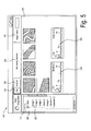
- Figure 5 illustrates the graphical user interface 200 as described with reference to figure 4a when the user has selected the grid view mode for example by selecting with the pointer 240 of the mouse the grid button 231 in the command bar of the graphical user interface 200.
- all images in the selected directory are displayed in the rendering space 210 side-by-side.
- the first spectrum 258 and the second spectrum 259 are displayed side-by-side with the images.
- Figure 6 shows the graphical user interface, as described with reference to figure 4a when the "set viewing direction" button 233 is selected with the pointer of the mouse.
- the images displayed in figure 6 have been imaged with the microscope of figure 2 , wherein in the electron microscope 2, the object 10 has been rotated with respect to the object region of the electron optical system 23 by using the positioning system 22.
- the a image 262 is displayed in the rendering space 210 of the graphical user interface 200. Furthermore, representations of a first, second, fourth and fifth image 261, 263, 264, 265 are displayed.
- the representations of each of these images comprises a frame, wherein the location and the form of each of the frames indicates a location and an extent of the respective imaged region relative to the imaged region of the third image 262.
- image data of the first, second, fourth and fifth image 261, 263, 264, 265 are displayed within the respective representations.
- representations of a first spectrum 266 and a second spectrum 267 are displayed in the rendering space 210.
- a location of the representation of the first spectrum 266 relative to the third image 262 depends on a location of the interaction region of the first spectrum relative to the imaged region of the third image.
- a location of the representation of the second spectrum 267 depends on a location of the interaction region of the second spectrum relative to the imaged region of the second image.
- the user When the user has selected the "set viewing direction" button 233 of the command bar, it is possible for the user to change the viewing direction, for example, by moving the mouse or by using arrow keys of the keyboard.
- the selectable viewing direction is indicated by arrows 271 and 270 in figure 6 .
Landscapes
- Chemical & Material Sciences (AREA)
- Analytical Chemistry (AREA)
- Engineering & Computer Science (AREA)
- Computer Vision & Pattern Recognition (AREA)
- Multimedia (AREA)
- Physics & Mathematics (AREA)
- General Physics & Mathematics (AREA)
- Optics & Photonics (AREA)
- Analysing Materials By The Use Of Radiation (AREA)
Abstract
Description
- The present invention relates generally to a method of operating a charged-particle microscope or a method of operating a combination of a charged-particle microscope with another microscope of a different type. More specifically, the invention is concerned with a method of operating a charged-particle microscope for managing a plurality of images which have been acquired at different microscope settings.
- In microscopic applications, it is typically necessary for a user to view a larger area of the object at a lower magnification in order to locate multiple small areas to be viewed. When the smaller area to be viewed is located, the user refocuses and switches the magnification. Thereby, the user typically generates a set of images of the object, which covers a range of magnifications. The user has to browse this set of images for identifying object features or for deciding at which locations of the object to acquire further images.
- However, when comparing images of widely different magnifications, it is difficult to see how they are related to each other.
- In the field of scanning electron microscopy, objects are often analyzed by using images of different detector configurations each of them revealing different characteristics of the object. For example, a secondary electron detector (SE detector) allows to identify topographic features of object. The resolution of the SE detector is typically 1 to 3.5 nm at an energy of the primary electron beam of 30kV, enabling very fine details of the surface topography to be resolved.
- A backscattered electron detector (BSE detector) is typically placed close to the exit opening of the electron optical system to capture electrons, which are reflected or backscattered at acute angles from the object. Since the intensity of the BSE signal is strongly related to the atomic number (Z) of the object, BSE images can provide information about the distribution of chemical elements in the sample. BSE detectors are typically solid-state devices, often with multiple components. For example, by switching of two of the four quadrants of a 4-Quadrant BSE detector, some shadowing can be created resulting in a better topographical contrast.
- Moreover, scanning electron microscopes are often provided with an energy-dispersive spectrometer (EDX detector). When the primary electron beam removes an inner shell electron from an atom of the object, characteristic X-rays are emitted when higher energy electrons fill the inner shell of the atom and release energy. These characteristic X-rays are measured by the EDX detector, resulting in a spectrum which may be used to identify the elemental composition of the object and to measure the abundance of specific elements.
- Therefore, a comprehensive study of an object with a scanning electron microscope may involve studying images of different magnifications which have been acquired by using different detectors from different locations on the specimen. However, it is typically difficult for the user to determine how these images are related to each other making the analysis of a complex object a time-consuming task.
- Accordingly, it is considered desirable to provide a method for operating a charged-particle microscope which allows a more efficient acquisition and analysis of image data of an object.
- A method of operating a charged-particle microscope, the method comprising: recording a first image of a first region of an object using the charged-particle microscope in a first setting; recording a second image of a second region of the object using the charged-particle microscope in a second setting, wherein the second setting differs from the first setting with respect to at least one of a kinetic energy of primary charged particles used for imaging, a detector setting used for imaging, a beam current of the charged particles used for imaging and a pressure in a measuring chamber of the charged-particle microscope; recording a third image of a third region of the object using the charged-particle microscope, wherein the first and second regions are contained at least partially within the third region; displaying at least a portion of the third image; displaying a representation of the first image at least partly within the displayed third image, wherein the representation of the first image includes a first indicator which is indicative of the first setting; displaying a representation of the second image at least partly within the displayed third image, wherein the representation of the second image includes a second indicator which is indicative of the second setting, and wherein the displayed second indicator is different from the displayed first indicator.
- The method may be in particular a computer-implemented method. The charged-particle microscope may for example be an electron microscope or a helium ion microscope. The electron microscope may be a scanning electron microscope or a transmission electron microscope.
- The third image may be read from a storage medium. The storage medium may be part of a computer system or a data base. Additionally or alternatively, the third image may be read via a signal line from a light microscope or from the charged-particle microscope.
- The first region of the object may for example be a region of the object which is scanned by the charged-particle beam for acquiring the first image.
- The first and/or second setting may be defined as a set of operational parameters of the charged-particle microscope which are specified at a time when the first image is acquired. The first and/or second setting may comprise at least one of a kinetic energy of the electron beam, a detector setting used for imaging, a beam current of the charged particles used for imaging and a pressure in a measuring chamber. The detector setting may comprise at least one of the following: a type of a detector used for acquiring the image, a number of the detectors used for acquiring the image and a value of an operational parameter of the one or more detectors used for imaging. The measuring chamber may be a vacuum chamber. The pressure may be measured at the time when the image is acquired.
- The operational parameters of the one or more detectors used for imaging may for example comprise: a detector voltage, identifier of detector segments of a 4-Quadrant-BSE detector used for imaging and an arrangement of the detector with respect to an object region of the charged-particle microscope.
- For example in the case of a scanning electron microscope, the detector used for acquiring the image may be one or more from a combination of the following: a secondary electron detector (SE detector), an in-lens secondary electron detector (annular SE detector), a backscattered electron detector (BSE detector) and/or an in-lens detector for detecting backscattered electrons.
- At least a portion of the third image is displayed. The third image may be displayed on a display of a computer. The computer may comprise a graphical user interface which is configured to display the third image in a rendering space of a window of the graphical user interface.
- A representation of the first image is displayed on the display. The representation of the first image may comprise an unfilled frame. In addition to the representation of the first image, also at least a portion of the first image may be displayed. For example, in case the first image comprises a non-overlapping region with the third image, image data of the first image which correspond to the non-overlapping region may be displayed in the non-overlapping region.
- The representation of the first image is displayed at least partially within the third image. In other words, the first image may be located within the third image or may comprise both an overlapping region with the third image and a non-overlapping region with the third image.
- The method may comprise determining the representation of the first image such that the representation of the first image is indicative of and/or depends on a location and an extent of the first region relative to the third region.
- The location of the first region relative to the third region may be expressed by a displacement vector representing a displacement of a reference point of the first region relative to a reference point of the third region. Additionally, the location of the first region relative to the third region may be expressed by angles by which the orientation of the first region relative to the third region is described. In other words, the location of the first region relative to the third region may be expressed in the same manner as the linear position and angular position of a rigid body.
- The extent may be a lateral extent, which is measured perpendicular to the optical axis of the charged-particle microscope. The lateral extent may be measured by projecting the surface topography of the imaged region of the object onto the object plane of the charged-particle microscope.
- The extent of the first region relative to the third region may be expressed for example by a scale factor or by a first and a second scale factors, wherein the first scale factor corresponds to a first coordinate axis and the second scale factor corresponds to a second coordinate axis, wherein the first coordinate axis is non-parallel to the second coordinate axis.
- The representation of the first image comprises a first indicator. The first indicator may be for example a color of the representation, a line pattern of the representation and/or an icon of the representation. The first indicator is indicative of the setting of the electron microscope at which the first image was taken. For example, a red-colored frame may indicate that the first image has been acquired by using an SE detector, wherein a blue-colored frame may indicate that the first image has been acquired by using a BSE detector.
- Each of the first and the second indicators may be determined from a group of pre-defined indicators. For example, the color "red" for the first indicator may chosen from the group of colors "red" and "blue".
- The first indicator may indicate a setting of the charged-particle microscope independently from the indicating of the location and extent of the first region by the location and the form of the representation of the first image. Accordingly, the second indicator may indicate a setting of the charged-particle microscope independently from the indicating of the extent and the location of the second region by the location and the form of the representation of the second image.
- The first and second indicator may indicate first and second settings independently from the extent and locations of the first and second region relative to the third region. Thereby, the first and second indicator may provide additional information about the first and second settings. This additional information may comprise a detector setting and/or a primary charged-particle beam setting.
- The second indicator is different from the first indicator. For example, the second indicator may be visibly different from the first indicator.
- Accordingly, a method is provided which allows to operate a charged-particle microscope in an efficient way. In particular, the method combines the information of an image with its context (i.e. the information provided by other images). Thereby, it is easier for a user to relate the features of an image to features of an object and to determine which images are necessary to conduct a comprehensive study of the object. Consequently, the method allows to conduct a thorough and comprehensive study of complex objects within a short time. According to an embodiment, the method further comprises recording the third image using a light microscope or the charged-particle microscope.
- Alternatively, the method may comprise recording the third image using a confocal laser scanning microscope, an atomic force microscope or a scanning tunneling microscope.
- According to an embodiment, the second indicator is different from the first indicator such that the difference indicates and/or is dependent on a difference of the kinetic energies of the primary charged particles of the first and the second setting and/or a difference of the detector settings of the first and the second setting.
- By way of example, the first indicator may depend on the detector setting and/or the energy of the charged-particle beam of the first setting. The second indicator may depend on the detector setting and/or the energy of the charged-particle beam of the second setting.
- According to a further embodiment, a form and a location of the representation of the first image is indicative of and/or dependent on an extent and a location of the first region of the object relative to the third region of the object; and a form and a location of the representation of the second image is indicative of and/or dependent on an extent and a location of the second region relative to the third region of the object.
- The form and location of the representation of the first image and the second image may be determined depending on a magnification factor of the third image. The magnification factor of the third image may be defined as a magnification of the displayed third image. In particular, a size of the representation of the first image may be determined by multiplying the extent of the first image with the magnification factor. The location of the representation of the first image relative to the third image may be determined by multiplying the location of the first region relative to the third region with the magnification factor.
- According to a further embodiment, the displayed second indicator has a color different from a color of the displayed first indicator. The color of the first indicator and the color of the second indicator may be visually distinguishable.
- According to a further embodiment, the displayed second indicator has a geometry different from a geometry of the displayed first indicator. The geometry of the first indicator and the geometry of the second indicator may be visually distinguishable.
- For example, the geometry of the first indicator may comprise an icon. The icon may indicate the first setting. The icon may for example comprise a symbol which represents the detector, which has been used when acquiring the first image. As a further example, the representation of the first image may comprise a frame. The line pattern of the frame may be determined from the group of a solid line, a dashed line and a dashed-dotted line, depending on the first setting.
- According to an embodiment, the charged-particle microscope is an electron microscope and a first detector is used for imaging of the first image and a second detector is used for imaging of the second image, wherein the first detector has a higher relative sensitivity for backscattered electrons than the second detector.
- For example, the first detector is a BSE detector and the second detector is an SE detector.
- According to an embodiment a first kinetic energy of the primary charged particles is used for imaging of the first image and a second kinetic energy of the primary charged particles is used for imaging of the second image, wherein the first kinetic energy is greater than 1.1 times the second kinetic energy.
- According to a further embodiment, a lateral extent of the first region of the object is greater than a lateral extent of the second region of the object; wherein the third image and the representations of the first and second images are displayed on a display medium; and wherein a lateral extent of the displayed representation of the first image on the display medium is greater than a lateral extent of the displayed representation of the second image on the display medium.
- A lateral extent of the first region may for example be a diameter of the first region, an area of the first region or a length of the first region along a coordinate axis.
- According to a further embodiment, an angle between a line between a center of the first region of the object and a center of the third region of the object and a line between a center of the second region of the object and a center of the third region of the object is a first angle; wherein an angle between a line between a center of the displayed representation of the first image and a center of the displayed third image and a line between a center of the representation of the second image and the center of the displayed third image is a second angle; and wherein an absolute value of a difference between the first angle and the second angle is less than 30 degrees.
- The absolute value of the difference between the first angle and the second angle may be less than 10 degrees, less than 5 degrees or less than 1 degree.
- Accordingly, it is possible for the user to recognize, based on the displayed representations of the first and second image, and the displayed third image the location of the first region and the second region relative to the third region. Thereby, it is possible for the user to see from the representations which portions of the object already have been imaged and which setting of the charged-particle microscope have been used for acquiring those images.
- According to an embodiment, the representation of the first image includes a frame representing a lateral extent of the first region.
- The frame may comprise lines, which are connected and arranged to define a region on the display. In other words, the frame may be an unfilled circle or an unfilled polygon, such as a rectangle. In the region enclosed by the frame, image data values of the third image are displayed in case the frame is located completely inside the third image. In case the frame has a non-overlapping region with the third image, image data of the first image may be displayed in the non-overlapping region. In case the frame is located outside of the third image, image data of the first image may be displayed inside the frame and outside the displayed third frame. A form of the frame relative to the displayed third image may correspond to an extent of the imaged region of the object relative to an extent of the third image. In particular, a size of the frame relative to a size of the displayed third image may correspond to an extent of the first region of the object relative to an extent of the third region. The size of the frame relative to the third image may be expressed by the size of the frame divided by the size of the third image. A location of the frame relative to the displayed third image may correspond to a location of the first region relative to the third region. The form and location of the frame may be determined depending on a magnification factor of the displayed third image. The magnification factor of the third image may be defined as a magnification of the displayed third image. In particular, a size of the frame may be determined by multiplying the extent of the first image with the magnification factor. The location of the frame relative to the third image may be determined by multiplying the location of the first region relative to the third region with the magnification factor.
- According to an embodiment, the method further comprises selecting one of the first and second images by selecting one of the representation of the first image and the representation of the second image and displaying the selected image.
- Selecting a representation may comprise selecting the displayed representation with a pointer of a mouse.
- According to an embodiment, a lateral extent of the displayed selected image on a display medium is greater than a lateral extent of the displayed representation of the respective image on the display medium.
- According to an embodiment, the method further comprises selecting a region within the displayed third image; determining a fourth region of the object based on the selected region within the displayed third image; and recording an image of the fourth region of the object using the electron microscope.
- Accordingly, it is possible for the user to identify a region of the object, where an image is to be acquired, based on the displayed third image and based on the displayed representations of the first and second image.
- According to a further embodiment a size of the fourth region of the object is at least 10 times smaller than a size of the third region of the object.
- According to an embodiment, the method further comprises: recording a fifth image of a fifth region of the object using a second microscope, and displaying a representation of the fifth image at least partially within the third image, wherein the representation of the fifth image includes an indicator, which is indicative of the second microscope.
- The indicator, which is indicative of the second microscope may be different, in particularly visually different, from the first indicator and the second indicator. The fifth image may be displayed at least partially within the third image. The fifth image may be recorded using the second microscope in a second setting. The indicator which is indicative of the second microscope may be further indicative of the setting of the second microscope.
- The second microscope may be a light microscope. The light microscope may comprise an optical system for imaging an object region onto a detector surface of an image sensor. Alternatively, the second microscope may be a confocal laser scanning microscope, an atomic force microscope, a scanning tunneling microscope or any type of microscope known in the art.
- Accordingly, there is provided a method which combines image data which are acquired by using different microscopic techniques. Thereby, it is possible for the user to conduct a thorough and efficient microscopic study of an object by combining different microscopes.
- According to an embodiment, a form and a location of the representation of the first image relative to the third image corresponds to an extent and a location of the first region of the object relative to the third region of the object; and a form and a location of the representation of the second image relative to the third image corresponds to an extent and a location of the second region relative to the third region of the object.
- The form of the representation of the first image may be for example a quadrilateral having angles of greater or less than 90 degrees. Thereby, the representation may indicate that the first region is in inclined with respect to the third region.
- The electron microscope may comprise a positioning system which is configured to rotate the object with respect to the object region of the charged-particle microscope. Thereby, the first, second and third image may correspond to different orientations of the object with respect to the object region of the charged-particle optical system.
- According to a further embodiment, the displaying of the third image, the displaying of the representation of the first image and the displaying of the representation of the second image is performed depending on a pre-selectable viewing direction.
- By way of example, in case the representation of the first image indicates that the first region is inclined with respect to the third region, the user may change a viewing direction such that the representation of the first image is shown as a rectangle or a square, indicating that the viewing direction is parallel to the optical axis of the charged-particle microscope at the time of acquiring the first image. Then, the first image and a representation of the third image may be displayed, wherein a form and a location of the representation of the third image indicates and/or is dependent on a location and extent of the third region relative to the first region.
- According to an embodiment, the method further comprises: acquiring a spectrum and/or a diffraction pattern from an interaction region of the charged-particle beam and the object; and displaying a representation of the spectrum and/or the diffraction pattern at least partially within the third image; wherein the representation of the spectrum and/or diffraction pattern includes an indicator of the spectrum and/or diffraction pattern.
- The spectrum may be for example an X-ray spectrum, a secondary ion mass spectrum or a cathodoluminescence spectrum. The diffraction pattern may for example be a pattern of diffracted backscattered electrons. The X-ray spectrum may be for example measured by an energy dispersive spectrometer (EDX spectrometer) or a wavelength dispersive spectrometer (WDS spectrometer). The pattern of diffracted backscattered electrons may be for example acquired by an electron backscattered diffraction detector (EBSD detector).
- A location of the representation of the spectrum and/or diffraction pattern relative to the third image may be indicative of and/or depend on a location of the interaction region relative to the location of the third image. The representation of the spectrum and/or the diffraction pattern may be for example a mark or an unfilled frame. The representation of the spectrum and/or diffraction pattern may be selectable. The displayed indicator of the spectrum and/or diffraction pattern may be different from indicators of representations of images, thereby indicating the presence of a spectrum or a diffraction pattern. An indicator of a representation of a spectrum may be different from an indicator of a representation of a diffraction pattern. The indicator may be indicative of and/or depend on characteristics of the spectrum and/or diffraction pattern. For example, the indicator of a spectrum may be indicative of and/or depend on an element, which is revealed by the spectrum. Further by way of example, the indicator of a diffraction pattern may be indicative of and/or depend on a crystallographic orientation.
- According to embodiment, there is provided a method of operating a user-interface of a charged-particle microscope, comprising: reading a first image of a first region of an object, wherein the first image corresponds to a first setting of the charged-particle microscope; reading a second image of a second region of an object, wherein the second image corresponds to a second setting of the charged-particle microscope, wherein the second setting differs from the first setting with respect to at least one of a kinetic energy of primary charged particles used for imaging, a detector setting used for imaging, a beam current of the primary charged particles used for imaging and a pressure in a measuring chamber of the charged-particle microscope; reading a third image of a third region of the object, wherein the first and second regions are contained at least partially within the third region; displaying at least a portion of the third image; displaying a representation of the first image at least partially within the displayed third image, wherein the representation of the first image includes a first indicator which is indicative of the first setting; displaying a representation of the second image at least partially within the displayed third image, wherein the representation of the second image includes a second indicator which is indicative of the second setting, and wherein the displayed second indicator is different from the displayed first indicator.
- The user interface may be a graphical user interface of a computer. The method may be a computer-implemented method. The computer having the graphical user-interface for performing the method may be in signal connection to a microscope or may be a computer which is isolated from microscopes. The images may be read from a memory of a computer or a data base. The images may be acquired by a charged-particle microscope or a light microscope. In other words, the group consisting of the first image, the second image and the third image may be acquired by using a light microscope, a charged-particle microscope or a combination of a light microscope and a charged-particle microscope.
- The first image corresponds to the first setting and the second image corresponds to the second setting. In other words, the first image is acquired using a charged-particle microscope at a first setting and the second image is acquired using a charged-particle microscope at a second setting.
- According to embodiments, there is provided a charged-particle microscope configured to perform the method according to the embodiments as described above.
- The foregoing as well as other advantageous features of the invention will be more apparent from the following detailed description of exemplary embodiments of the invention with reference to the accompanying drawings. It is noted that not all possible embodiments of the present invention necessarily exhibit each and every, or any, of the advantages identified herein.
- Figure 1A:
- shows an image of a scanning electron microscope which is acquired by using an chamber mounted SE detector.
- Figure 1B:
- shows an image of a scanning electron microscope which is acquired by using a an in-lens SE detector.
- Figure 2:
- is a schematic illustration of a microscope system according to an exemplary embodiment;
- Figure 3:
- is a flow-chart illustrating a method according to an exemplary embodiment;
- Figure 4A:
- is a schematic illustration of a graphical user interface in the "oriented view" mode according to an exemplary embodiment;
- Figure 4B:
- is an illustration of the correspondence between imaged regions of the object and the images and representations shown in the graphical user interface according to the exemplary embodiment shown in
figure 4A ; - Figure 5:
- is a schematic illustration of the graphical user interface shown in
figure 4A in the "grid view" mode; and - Figure 6:
- is a schematic illustration of the graphical user interface shown in
figure 4A in the "select viewing direction" mode. -
Figure 1A and 1B show images acquired by an electron microscope. The micrograph offigure 1A has been taken by using a chamber mounted SE detector. Images of a chamber mounted SE detector allow to identify large scale topographic features of object. -
Figure 1B has been acquired by using an in-lens SE detector. - While the SE image in
Figure 1A shows some topographical information on a large scale, the in-lens image shows topographic and compositional contrast and suppresses charging or edge enhancement effects. - However, comparing
figure 1A and figure 1B , it is difficult to judge just by looking at the images, whether they refer to the same object and whether the imaged object region offigure 1A overlaps with the imaged object region shown offigure 1B . - This problem is in particular aggravated by the fact that images, which have been acquired from an object often cover a wide range of magnification. The magnification of a scanning electron microscope can be controlled over a comparatively wide range of up to six orders of magnitude.
- Accordingly, it is considered desirable to provide a method for operating a charged-particle microscope which allows a more efficient acquisition and analysis of image data of an object.
-
Figure 2 shows amicroscope system 1 according to an exemplary embodiment. Themicroscope system 1 comprises anelectron microscope 2 and alight microscope 3. Theelectron microscope 2 has an electronoptical system 23 which comprises anobjective lens 25. The electronoptical system 23 is designed such that a beam of electrons is focusable onto anobject 10, which is positioned by apositioning system 22 in an object region of the electronoptical system 23. Acomputer 4 is in signal communication with the electronoptical system 23. Thecomputer 4 is configured to control the electronoptical system 23 via signals transmitted on asignal line 54. Theelectron microscope 2 comprises a backscattered electron detector 24 (also denoted as BSE detector) and a secondary electron detector 26 (also denoted as SE detector). TheBSE detector 24 is arranged upstream of the object region and surrounds an exit opening of the electronoptical system 23. Thecomputer 4 is in signal communication with the BSE detector via asignal line 51. Thecomputer 4 is configured to read signals which represent image data and which are transmitted from the BSE detector via thesignal line 51 to thecomputer 4. The computer is further configured to control via thesignal line 51 settings of the BSE detector. Theelectron microscope 2 further comprises a secondary electron detector 26 (also denoted as SE detector). Themicroscopy system 1 therefore comprises two electron detectors wherein theBSE detector 24 has a higher sensitivity for backscattered electrons than theSE detector 26. - The
SE detector 26 is in signal communication with thecomputer 4 viasignal line 52. Thecomputer 4 is configured to read signals which are transmitted from theSE detector 26 and which represent image data. Thecomputer 4 is further configured to control viasignal line 52 settings of the SE detector. - The
electron microscope 2 further comprises avacuum chamber 21 and avacuum pumping system 27. Thevacuum pumping system 27 and thevacuum chamber 21 are designed such that the vacuum chamber is evacuatable to a vacuum of between high vacuum and approximately 22 Torr, depending on the settings of theelectron microscope 2. - The
electron microscope 2 further comprises apositioning system 22. Thepositioning system 22 is designed as a six-axis stage. In other words, theobject holder 11, which is mounted on thepositioning system 22 and to which theobject 10 is attached, is movable by thepositioning system 22 with six degrees of freedom. It is also conceivable that thepositioning system 22 is configured such that theobject holder 11 is movable with between one and five degrees of freedom. Viasignal line 55, thecomputer 4 transmits position control signals to thepositioning system 22 to position theobject 10 with respect to the object region of the electronoptical system 23. - The
computer 4 is further configured such that position control signals transmitted to thepositioning system 22 are recorded by thecomputer 4. Thecomputer 4 is configured to determine locations of regions of theobject 10 which are imaged by the electron beam based on the recorded signals for controlling the position of theobject 10. For example, thecomputer 4 may determine from the recorded position control signals a position and an orientation of a second region imaged by theelectron microscope 2 relative to a first region imaged by theelectron microscope 2. - For example, the
computer 4, after having retrieved signals from theSE detector 26 or theBSE detector 24 which represent a first image, may transmit position control signals to thepositioning system 22 to displace the object 50 micrometers along an x-axis. Then, the computer generates control signals for the electronoptical system 23 to acquire a second image. The imaged region of the second image relative to the imaged region of the first image may then be determined to be shifted by -50 micrometers along the x-axis. - Between the acquiring of the first image and the acquiring of the second image, the
computer 4 may also change a setting of the electronoptical system 23. Thecomputer 4 is configured to transmit field of view control signals viasignal line 54 to the electronoptical system 23 to control the field of view of the electronoptical system 23. For example, the field of view of an overview image may be taken with a wider field of view and at a lower resolution than a detail image. Thecomputer 4 is configured to record the control signals transmitted to the electronoptical system 23 for setting the field of view. - Hence, the
computer 4 is configured calculate based on the position control signals and the field of view control signals a relative position and orientation of two imaged regions of theobject 10. - Additionally or alternatively, in case the first and second image overlap, the
computer 4 may be configured to determine the field of view of the second image relative to the field of view of the first image by performing image processing routines on image data values of the first and second image. For example, thecomputer 4 may apply an edge detection filter for locating edges of the surface topography within the images. Thereby, it is possible to determine the imaged region of the second image with respect to the imaged region of the first image with an accuracy which corresponds to a resolution of theelectron microscope 2. - The
electron microscope 2 further comprises anEDX detector 28 for an energy-resolved detection of X-rays which are emitted from an interaction region where an electron beam of the electronoptical system 23 interacts with theobject 10. - The
EDX detector 28 is in signal communication with thecomputer 4 viasignal line 57. Thecomputer 4 is configured to receive signals representing EDX spectra and to generate files containing the data of spectra. However, it is also conceivable that a further computer which is separate from thecomputer 4 is in signal communication with the EDX viasignal line 57. Thecomputer 4 is further configured to record positioning signals which are generated by thecomputer 4 and transmitted viasignal line 55 to thepositioning system 22. The computer is further configured to determine a working distance of the electronoptical system 23 from operation parameters of the particleoptical system 23. Thecomputer 4 is configured to calculate depending on values of the operation parameters of the particleoptical system 23 and from the recorded positioning signals transmitted to thepositioning system 22 the location of the interaction region with respect to the imaged region of the third image. Additionally or alternatively to the EDX detector, theelectron microscope 3 may comprise at least one of a wavelength dispersive spectrometer (WDS spectrometer), an electron backscattered diffraction detector (EBSD detector) or any other spectrometers for charged-particles or emitted light known in the art. - The
microscope system 1 further comprises alight microscope 3. Thelight microscope 3, theelectron microscope 2 and thesample holder 11 may be designed such that thesample holder 11 is transferable between thelight microscope 3 and theelectron microscope 2. InFigure 2 , this is indicated byarrow 12. Thelight microscope 3 further comprises apositioning system 34. Thepositioning system 34 of thelight microscope 3 is designed such that theobject 10 which is attached to theobject holder 11 is positionable relative to an object region of an optical system of thelight microscope 3. The optical system of thelight microscope 3 comprises anobjective lens 31 and animaging lens system 32. The optical system of thelight microscope 3 is designed such that the object region of the optical system of thelight microscope 3 is imaged onto animage sensor 33 of thelight microscope 3. Thecomputer 4 is configured to receive signals of theimage sensor 33 viasignal line 53 and to generate image data from the received signals. - As an alternative to the
computer 4, it is also conceivable that a first computer is in signal communication with thepositioning system 34 of thelight microscope 3 viasignal line 56 and in signal communication with theimage sensor 33 viasignal line 53; and second computer is in signal communication with thepositioning system 22 of the electron microscope viasignal line 55 and with the electronoptical system 23 viasignal line 54. The first and the second computer may be separate (i.e. they do not share common components). It is also conceivable that each of the first computer and the second computer comprise network interfaces for data communication over a common data network. The first computer and the second computer may be in data communication with a data base, which is configured to store images, which have been acquired by theelectron microscope 2 or thelight microscope 3. - The
computer 4 comprises adisplay 41. Thecomputer 4 further comprises a graphical user interface that resides within a machine-readable media 42 to direct the operation of thecomputer 4 and based on the position control signals of thepositioning systems - The
sample holder 11 may comprise marks on anupper surface 11A of thesample holder 11. The marks are imageable by thelight microscope 3 and by theelectron microscope 2. For example, the marks may be designed such that they are reflective for light of wavelengths which are used for imaging in thelight microscope 3. The marks may further comprise a topography or a chemical composition which is imageable by theelectron microscope 2. Thecomputer 4 is configured such that the marks are detectable in images of thelight microscope 3 and images of theelectron microscope 2. Thecomputer 4 is further configured to determine the location and extent of an imaged region of an image acquired by theelectron microscope 2 relative to the imaged region of an image acquired by thelight microscope 3 based on the detected marks in the images. -
Figure 3 is a flowchart which illustrates an exemplary embodiment. The embodiment is described with reference to themicroscope system 1, which is illustrated infigure 2 . A first, second and a third image are recorded 100 by using theelectron microscope 2 or thelight microscope 3. Each of the images is generated by imaging a respective region of the object. For example, an image is acquired by theelectron microscope 2 by scanning the region of the surface of the object with an electron beam of the electronoptical system 23. An image acquired by thelight microscope 3 is acquired by imaging a region of the object onto theimage sensor 33. Thecomputer 4 is configured to determine 101 from settings of theelectron microscope 2 and/or from settings of thelight microscope 3 the lateral extent of each of the regions of the first, second and third image. The determined lateral extent may be a relative extent between the first, second and third image. A lateral extent of the region may be for example a diameter, an area or a length along a coordinate axis. - The
computer 4 is further configured to determine 102 a location and an extent of each of the first and the second regions relative to the third region. Thecomputer 4displays 103 the third image on adisplay 41 of thecomputer 4. Representations of the first and second image are displayed on thedisplay 41 by displaying a frame, wherein a form of the frame relative to the displayed third image corresponds to an extent of the imaged region of the object relative to an extent of the third region. - The
computer 4 is further configured to determine 104 a first identifier for the representation of the first image and a second identifier for the representation of the second image. Then, the representations of the first and second image are displayed 105 with their identifiers. For example, the representation of the first image may be displayed on thedisplay 41 having a red-colored frame, indicating that the first image was acquired by using theSE detector 26 of theelectron microscope 2. Correspondingly, the representation of the second image may be displayed on thedisplay 41 having a blue-colored frame, indicating that the image was acquired by using theBSE detector 24 of theelectron microscope 2. - Each of the representation of the first image and the representation of the second image are configured to be selectable. In other words, the
computer 4 is configured such that the representation is selectable by an input from the user. For example, thecomputer 4 may stay 106 in a waiting loop until the frame of the first and/or second image is selected with the pointer of the mouse. - The
computer 4 is further configured to display 107 the first image on thedisplay 41 upon selection of the representation of the first image. Accordingly, upon selection of the representation of the second image, the second image is displayed on thedisplay 41. -
Figure 4A shows agraphical user interface 200, which is displayed on thecomputer display 41 according to an exemplary embodiment. Thegraphical user interface 200 as displayed infigure 4A is described with reference to themicroscope system 1 as displayed infigure 2 . Thegraphical user interface 200 comprises arendering space 210. Therendering space 210 is configured for rendering images which have been generated using theelectron microscope 2 and thelight microscope 3 of themicroscope system 1. Thegraphical user interface 200 further comprises adirectory tree view 220. Thedirectory tree view 220 is configured to displaydirectories 221 and filenames 222 in a hierarchical list. Thecomputer 4 may configured such that upon selection of adirectory 221 in thedirectory tree view 220, the image files 222 contained in thedirectory 221 are selected to be a group of images, wherein each image of the group of images is displayed as a image or as a representation in therendering space 210. Thegraphical user interface 200 further comprises a command bar, which comprises a button for selecting agrid view 231 and a button for selecting an orientedview 230. Thereby, the graphical user interface is configured to be switchable between a grid view mode of thegraphical user interface 200 and an oriented view mode of thegraphical user interface 200. The command bar further comprises aninput field 232 for inputting a magnification factor. - Upon selection of the
directory 221 in thedirectory tree view 220, thecomputer 4 determines athird image 212 from the images in thedirectory 221. Thethird image 212 is displayed in therendering space 210 of thegraphical user interface 200. Thethird image 212 may be determined for example by determining the image with the widest field of view of the images in thedirectory 221. Thethird image 212 shows object features 217. Arepresentation 211 of the first image is displayed in therendering space 210. Therepresentation 211 of the first image comprises a frame. The frame of therepresentation 211 of the first image comprises a first indicator, which is a solid line pattern, indicating that the image has been acquired by using the SE-detector 26 of theelectron microscope 2. - The computer may also be configured to display concurrently with the image data of the third image a representation of the third image. Accordingly, in
Figure 4A , thethird image 212 is provided with a frame which also comprises continuous lines, indicating that the image has been acquired by using theSE detector 26 of theelectron microscope 2. - The
computer 4 is further configured to display arepresentation 213 of the second image. Therepresentation 213 of the second image comprises a second indicator which is a dashed-and-dotted line pattern, indicating that the second image has been acquired by using theBSE detector 24. - The
computer 4 is further configured that upon selection of a region ofinterest 214 with apointer 240 of a mouse of thecomputer 4, thecomputer 4 identifies image data values which correspond to the selected region ofinterest 214 from all images of thedirectory 221. - Accordingly, it is possible for the user to directly compare portions of images, which correspond to a common region of the object, wherein the common region has been selected with the region of interest. Thereby, it is easier for the user to identify object features which appear in images of different microscope settings.
- The computer is further configured that upon selection of a region of
interest 240 by the user, an object region is defined, where a fourth image is taken by the electron microscope. - In the
graphical user interface 200, also a representation of afifth image 216 is shown. The representation of thefifth image 216 comprises a quadrilateral having four angles of greater or less than 90°. Thereby, the representation of thefifth image 216 indicates that the fifth image corresponds to an imaged region of the object which is inclined with respect to the imaged regions of thethird image 212. - The
computer 4 is further configured to display a representation of afirst spectrum 218 and a representation of asecond spectrum 219. The first and second spectrum have been acquired by using theEDX detector 28 of theelectron microscope 2. The representation of thefirst spectrum 218 comprises a frame. The frame indicates the location of the interaction region where the electron beam has interacted with the object and from which the X-rays have been emitted. The representation of thefirst spectrum 218 further comprises an identifier, which comprises a name "spectrum 1" of the first spectrum. Thegraphical user interface 200 is further configured that the representation of thefirst spectrum 218 is selectable. When the representation of thefirst spectrum 218 is selected (e.g. by using the pointer of the mouse), the spectrum is displayed in therendering space 210. -
Figure 4B schematically illustrates how imaged regions of the object correspond to images and representations of images shown in thegraphical user interface 200, which has been described with reference toFigure 4A .Figure 4B shows object features 217A which are located on a surface of the object and which are imaged by theelectron microscope 2. Theobjects 217A are imaged with a first field of view defining afirst region 311 of the object for acquiring the first image. Then, by controlling thepositioning system 22, the object is moved laterally with respect to the optical axis such that a center of the field of view of the microscope is shifted from point P to point Q on the object. Furthermore, the lateral width of the field of view is widened. At the new position, the third image is acquired by scanning thethird region 312. Then, by controlling thepositioning system 22, the object is again moved laterally such that the center of the field of view is shifted from point Q to point R and the lateral width of the field of view is narrowed. Then, the second image is acquired by scanning asecond region 313. - The
third image 212 and representations of thefirst image 211 and thesecond image 213 are displayed by thegraphical user interface 200 shown infigure 4A . The location and form of the representation of thefirst image 211 relative to thethird image 212 is determined such that it depends on and/or is indicative of the relative location and extent of thefirst region 311 relative to thethird region 312. Accordingly, the location and form of the representation of thesecond image 213 relative to thethird image 212 is determined such that it depends on and/or is indicative of the relative location and extent of thesecond region 313 relative to thethird region 312. This is indicated inFigure 4B bydouble arrow 350. - A first line between a center of the
first region 311 and the center of thethird region 312 and a second line between the center of thesecond region 313 and the center of thethird region 312 form an angle ω. A third line between the center of thethird image 212 and the center of thefirst image 211 and a fourth line between the center of thethird image 212 and the center of thesecond image 213 form an angle Ω. An absolute difference between ω and Ω amounts to less than 30 degrees. Thereby, the relative locations of thefirst image 211 andsecond image 213 compared to thethird image 212 is indicative of the relative locations of thefirst region 311 and thesecond region 313 compared to thethird region 312. -
Figure 5 illustrates thegraphical user interface 200 as described with reference tofigure 4a when the user has selected the grid view mode for example by selecting with thepointer 240 of the mouse thegrid button 231 in the command bar of thegraphical user interface 200. As shown infigure 5 , all images in the selected directory are displayed in therendering space 210 side-by-side. In the grid view mode also thefirst spectrum 258 and thesecond spectrum 259 are displayed side-by-side with the images. -
Figure 6 shows the graphical user interface, as described with reference tofigure 4a when the "set viewing direction"button 233 is selected with the pointer of the mouse. The images displayed infigure 6 have been imaged with the microscope offigure 2 , wherein in theelectron microscope 2, theobject 10 has been rotated with respect to the object region of the electronoptical system 23 by using thepositioning system 22. - As shown in
figure 6 , the aimage 262 is displayed in therendering space 210 of thegraphical user interface 200. Furthermore, representations of a first, second, fourth andfifth image third image 262. In addition to the representations, also image data of the first, second, fourth andfifth image - Furthermore, representations of a
first spectrum 266 and asecond spectrum 267 are displayed in therendering space 210. A location of the representation of thefirst spectrum 266 relative to thethird image 262 depends on a location of the interaction region of the first spectrum relative to the imaged region of the third image. A location of the representation of thesecond spectrum 267 depends on a location of the interaction region of the second spectrum relative to the imaged region of the second image. - When the user has selected the "set viewing direction"
button 233 of the command bar, it is possible for the user to change the viewing direction, for example, by moving the mouse or by using arrow keys of the keyboard. The selectable viewing direction is indicated byarrows figure 6 .
Claims (15)
- A method of operating a charged-particle microscope (2), the method comprising:recording a first image of a first region (311) of an object (10) using the charged-particle microscope (2) in a first setting;recording a second image of a second region (313) of the object (10) using the charged-particle microscope (2) in a second setting, wherein the second setting differs from the first setting with respect to at least one of a kinetic energy of primary charged particles used for imaging, a detector setting used for imaging, a beam current of the primary charged particles used for imaging and a pressure in a measuring chamber (21) of the charged-particle microscope (2);reading a third image (212) of a third region (312) of the object (10),wherein the first and second regions (311, 313) are contained at least partially within the third region (312);displaying at least a portion of the third image (212);displaying a representation of the first image (211) at least partially within the displayed third image (212), wherein the representation of the first image (211) includes a first indicator which is indicative of the first setting;displaying a representation of the second image (213) at least partially within the displayed third image (212), wherein the representation of the second image (213) includes a second indicator which is indicative of the second setting, and wherein the displayed second indicator is different from the displayed first indicator.
- The method of claim 1, further comprising: recording the third image using a light microscope or the charged-particle microscope.
- The method of claim 1 or 2, wherein the displayed second indicator has a color different from a color of the displayed first indicator, and/or wherein the displayed second indicator has a geometry different from a geometry of the displayed first indicator.
- The method of any one of claims 1 to 3, wherein the charged-particle microscope is an electron microscope (2) and a first detector (24) is used for imaging of the first image and a second detector (26) is used for imaging of the second image, wherein the first detector (24) has a higher relative sensitivity for backscattered electrons than the second detector (26).
- The method of any one of claims 1 to 4, wherein a lateral extent of the first region (311) of the object (10) is greater than a lateral extent of the second region (313) of the object;
wherein the third image (212) and the representations of the first and second images (211, 213) are displayed on a display medium (41); and wherein a lateral extent of the displayed representation of the first image (211) on the display medium (41) is greater than a lateral extent of the displayed representation of the second image (213) on the display medium (41). - The method of any one of claims 1 to 5, wherein an angle between a line between a center of the first region (311) of the object (10) and a center of the third region (312) of the object (10) and a line between a center of the second region (313) of the object (10) and a center of the third region (312) of the object (10) is a first angle (ω);
wherein an angle between a line between a center of the displayed representation of the first image (211) and a center of the displayed third image (212) and a line between a center of the representation of the second image (213) and the center of the displayed third image (212) is a second angle (Ω); and
wherein an absolute value of a difference between the first angle and the second angle is less than 30°. - The method of any one of claims 1 to 6, wherein the representation of the first image (211) includes a frame representing the lateral extent of the first region.
- The method of any one of claims 1 to 7, further comprising selecting one of the first and second images by selecting one of the representation of the first image (211) and the representation of the second image (213) and displaying the selected image.
- The method according to claim 8, wherein a lateral extent of the displayed selected image on a display medium (41) is greater than a lateral extent of the displayed representation of the respective image on the display medium (41).
- The method of any one of claims 1 to 9, further comprising:selecting a region (214) within the displayed third image (212);determining a fourth region of the object (10) based on the selected region (214) within the displayed third image (212); andrecording an image of the fourth region of the object (10) using the electron microscope (2).
- The method of any one of claims 1 to 10, further comprising:recording a fifth image of a fifth region of the object (10) using a second microscope (3), anddisplaying a representation of the fifth image at least partially within the third image (212), wherein the representation of the fifth image includes an indicator, which is indicative of the second microscope (3).
- The method of any one of claims 1 to 11, wherein a form and a location of the representation of the first image (211) relative to the third image (212) corresponds to an extent and a location of the first region (311) of the object (10) relative to the third region (312) of the object (10);
and wherein a location and form of the representation of the second image (213) relative to the third image (212) corresponds to a location and extent of the second region (313) relative to the third region (312) of the object (10). - The method of any one of claims 1 to 12, further comprising:acquiring a spectrum and/or a diffraction pattern from an interaction region of the charged-particle beam and the object; anddisplaying a representation of the spectrum (218) and/or the diffraction pattern at least partially within the third image (212); wherein the representation of the spectrum (218) and/or diffraction pattern includes an indicator of the spectrum and/or diffraction pattern.
- A method of operating a user-interface of a charged-particle microscope (2), comprising:reading a first image of a first region (311) of an object (10), wherein the first image corresponds to a first setting of the charged-particle microscope (2);reading a second image of a second region (313) of the object (10),wherein the second image corresponds to a second setting of the charged-particle microscope (2);wherein the second setting differs from the first setting with respect to at least one of a kinetic energy of primary charged particles used for imaging,a detector setting used for imaging, a beam current of the primary charged particles used for imaging and a pressure in a measuring chamber (21) of the charged-particle microscope (2);reading a third image (212) of a third region (312) of the object (10),wherein the first and second regions (311, 313) are contained at least partially within the third region (312);displaying at least a portion of the third image (212);displaying a representation of the first image (211) at least partially within the displayed third image (212), wherein the representation of the first image (211) includes a first indicator which is indicative of the first setting;displaying a representation of the second image (213) at least partially within the displayed third image (212),wherein the representation of the second image (213) includes a second indicator which is indicative of the second setting, and wherein the displayed second indicator is different from the displayed first indicator.
- A microscope system (1) comprising a charged-particle microscope (2), wherein the microscope system (1) is configured to perform the method according to any one of claims 1 to 14.
Priority Applications (4)
| Application Number | Priority Date | Filing Date | Title |
|---|---|---|---|
| EP10014245A EP2450936B1 (en) | 2010-11-03 | 2010-11-03 | Microscope system, method for operating a charged-particle microscope |
| JP2011240527A JP4942853B2 (en) | 2010-11-03 | 2011-11-01 | Microscope system, method for operating charged particle microscope |
| US13/287,927 US8426812B2 (en) | 2010-11-03 | 2011-11-02 | Microscope system, method for operating a charged-particle microscope |
| CN201110462520.0A CN102543638B (en) | 2010-11-03 | 2011-11-03 | Microscopic system and the microscopical method of operating band charged particle |
Applications Claiming Priority (1)
| Application Number | Priority Date | Filing Date | Title |
|---|---|---|---|
| EP10014245A EP2450936B1 (en) | 2010-11-03 | 2010-11-03 | Microscope system, method for operating a charged-particle microscope |
Publications (2)
| Publication Number | Publication Date |
|---|---|
| EP2450936A1 true EP2450936A1 (en) | 2012-05-09 |
| EP2450936B1 EP2450936B1 (en) | 2013-03-13 |
Family
ID=43608040
Family Applications (1)
| Application Number | Title | Priority Date | Filing Date |
|---|---|---|---|
| EP10014245A Active EP2450936B1 (en) | 2010-11-03 | 2010-11-03 | Microscope system, method for operating a charged-particle microscope |
Country Status (4)
| Country | Link |
|---|---|
| US (1) | US8426812B2 (en) |
| EP (1) | EP2450936B1 (en) |
| JP (1) | JP4942853B2 (en) |
| CN (1) | CN102543638B (en) |
Cited By (5)
| Publication number | Priority date | Publication date | Assignee | Title |
|---|---|---|---|---|
| EP2697815A4 (en) * | 2011-04-14 | 2014-09-10 | Coxem Co Ltd | Combine apparatus of scanning electron microscope and energy dispersive x-ray spectroscopy |
| EP2835817A1 (en) * | 2013-08-09 | 2015-02-11 | Carl Zeiss Microscopy Ltd. | Method and data analysis system for semi-automated particle analysis using a charged particle beam |
| EP3654360A3 (en) * | 2018-11-15 | 2020-06-17 | Jeol Ltd. | Scanning electron microscope and image processing method |
| DE102019126200A1 (en) * | 2019-09-27 | 2021-04-01 | Carl Zeiss Microscopy Gmbh | EDX process |
| DE102020102502A1 (en) | 2020-01-31 | 2021-08-05 | Carl Zeiss Microscopy Gmbh | Process, particle beam system and computer program product for energy dispersive X-ray spectroscopy |
Families Citing this family (18)
| Publication number | Priority date | Publication date | Assignee | Title |
|---|---|---|---|---|
| US8704176B2 (en) * | 2011-08-10 | 2014-04-22 | Fei Company | Charged particle microscope providing depth-resolved imagery |
| NL1039512C2 (en) * | 2012-04-02 | 2013-10-03 | Univ Delft Tech | Integrated optical and charged particle inspection apparatus. |
| US20130271575A1 (en) * | 2012-04-11 | 2013-10-17 | Zspace, Inc. | Dynamically Controlling an Imaging Microscopy System |
| JP5464535B1 (en) * | 2013-07-23 | 2014-04-09 | 株式会社日立ハイテクノロジーズ | Charged particle beam apparatus capable of easily analyzing desired location with EBSD detector and control method thereof |
| CN105593966B (en) * | 2013-10-08 | 2017-05-24 | 株式会社日立高新技术 | Charged particle beam device and charged particle beam device control method |
| DE102014008105B4 (en) | 2014-05-30 | 2021-11-11 | Carl Zeiss Multisem Gmbh | Multi-beam particle microscope |
| DE102014008083B9 (en) | 2014-05-30 | 2018-03-22 | Carl Zeiss Microscopy Gmbh | particle beam |
| DE102014008383B9 (en) | 2014-06-06 | 2018-03-22 | Carl Zeiss Microscopy Gmbh | Particle beam system and method of operating a particle optic |
| CN104459972B (en) * | 2014-12-25 | 2017-11-24 | 中国科学院化学研究所 | It is positive to be inverted the micro- photonics systems of integration |
| US11900469B2 (en) * | 2015-02-03 | 2024-02-13 | State Farm Mutual Automobile Insurance Company | Point-of-service tool for entering claim information |
| US10453650B2 (en) * | 2015-11-25 | 2019-10-22 | Hitachi High-Technologies Corporation | Charged particle beam apparatus, observation method using charged particle beam apparatus, and program |
| EP3455664A1 (en) * | 2016-05-12 | 2019-03-20 | Life Technologies Corporation | Systems, methods, and apparatuses for image capture and display |
| US10203491B2 (en) * | 2016-08-01 | 2019-02-12 | Verily Life Sciences Llc | Pathology data capture |
| EP3547675A4 (en) * | 2016-11-24 | 2020-04-22 | Nikon Corporation | Image processing device, microscope system, image processing method, and computer program |
| US11010914B2 (en) * | 2016-11-24 | 2021-05-18 | Nikon Corporation | Image processing device, microscope system, image processing method, and program |
| JP6796524B2 (en) * | 2017-03-23 | 2020-12-09 | 日本電子株式会社 | Image processing equipment, observation equipment, and image processing methods |
| EP3637167B1 (en) * | 2018-10-11 | 2024-12-04 | Baden-Württemberg Stiftung gGmbH | Area scanning confocal microscopy (ascm) |
| US12525424B2 (en) | 2020-11-16 | 2026-01-13 | Hitachi High-Tech Corporation | Charged particle beam apparatus and report creation method |
Citations (4)
| Publication number | Priority date | Publication date | Assignee | Title |
|---|---|---|---|---|
| US20030193026A1 (en) * | 2002-04-11 | 2003-10-16 | Keyence Corporation | Electron microscope, method for operating the same, and computer-readable medium |
| US20060210129A1 (en) * | 2002-07-30 | 2006-09-21 | Deutsches Krebsforschungzentrum | Method and apparatus for multiple labeling detection and evaluation of a plurality of particles |
| US7485858B1 (en) * | 2005-12-06 | 2009-02-03 | Hitachi High-Technologies Corporation | Inspection method for semiconductor wafer and apparatus for reviewing defects |
| US20100091362A1 (en) * | 2008-10-15 | 2010-04-15 | Kabushiki Kaisha Topcon | Complex type microscopic device |
Family Cites Families (3)
| Publication number | Priority date | Publication date | Assignee | Title |
|---|---|---|---|---|
| JP4383950B2 (en) * | 2004-04-23 | 2009-12-16 | 株式会社日立ハイテクノロジーズ | Charged particle beam adjustment method and charged particle beam apparatus |
| US8026491B2 (en) * | 2006-03-08 | 2011-09-27 | Hitachi High-Technologies Corporation | Charged particle beam apparatus and method for charged particle beam adjustment |
| DE102006061978A1 (en) * | 2006-12-21 | 2008-06-26 | Forschungszentrum Jülich GmbH | Electron microscope and method for measuring defocus spread |
-
2010
- 2010-11-03 EP EP10014245A patent/EP2450936B1/en active Active
-
2011
- 2011-11-01 JP JP2011240527A patent/JP4942853B2/en active Active
- 2011-11-02 US US13/287,927 patent/US8426812B2/en active Active
- 2011-11-03 CN CN201110462520.0A patent/CN102543638B/en active Active
Patent Citations (4)
| Publication number | Priority date | Publication date | Assignee | Title |
|---|---|---|---|---|
| US20030193026A1 (en) * | 2002-04-11 | 2003-10-16 | Keyence Corporation | Electron microscope, method for operating the same, and computer-readable medium |
| US20060210129A1 (en) * | 2002-07-30 | 2006-09-21 | Deutsches Krebsforschungzentrum | Method and apparatus for multiple labeling detection and evaluation of a plurality of particles |
| US7485858B1 (en) * | 2005-12-06 | 2009-02-03 | Hitachi High-Technologies Corporation | Inspection method for semiconductor wafer and apparatus for reviewing defects |
| US20100091362A1 (en) * | 2008-10-15 | 2010-04-15 | Kabushiki Kaisha Topcon | Complex type microscopic device |
Cited By (7)
| Publication number | Priority date | Publication date | Assignee | Title |
|---|---|---|---|---|
| EP2697815A4 (en) * | 2011-04-14 | 2014-09-10 | Coxem Co Ltd | Combine apparatus of scanning electron microscope and energy dispersive x-ray spectroscopy |
| EP2835817A1 (en) * | 2013-08-09 | 2015-02-11 | Carl Zeiss Microscopy Ltd. | Method and data analysis system for semi-automated particle analysis using a charged particle beam |
| US20150046097A1 (en) * | 2013-08-09 | 2015-02-12 | Carl Zeiss Microscopy Ltd. | Method and data analysis system for semi-automated particle analysis using a charged particle beam |
| US10955368B2 (en) | 2013-08-09 | 2021-03-23 | Carl Zeiss Microscopy Ltd. | Method and data analysis system for semi-automated particle analysis using a charged particle beam |
| EP3654360A3 (en) * | 2018-11-15 | 2020-06-17 | Jeol Ltd. | Scanning electron microscope and image processing method |
| DE102019126200A1 (en) * | 2019-09-27 | 2021-04-01 | Carl Zeiss Microscopy Gmbh | EDX process |
| DE102020102502A1 (en) | 2020-01-31 | 2021-08-05 | Carl Zeiss Microscopy Gmbh | Process, particle beam system and computer program product for energy dispersive X-ray spectroscopy |
Also Published As
| Publication number | Publication date |
|---|---|
| EP2450936B1 (en) | 2013-03-13 |
| US20120104250A1 (en) | 2012-05-03 |
| JP4942853B2 (en) | 2012-05-30 |
| JP2012099481A (en) | 2012-05-24 |
| US8426812B2 (en) | 2013-04-23 |
| CN102543638B (en) | 2016-03-09 |
| CN102543638A (en) | 2012-07-04 |
Similar Documents
| Publication | Publication Date | Title |
|---|---|---|
| EP2450936B1 (en) | Microscope system, method for operating a charged-particle microscope | |
| US8450215B2 (en) | Particle beam systems and methods | |
| USRE44035E1 (en) | Apparatus for correlating an optical image and a SEM image and method of use thereof | |
| CN105529235B (en) | Charged particle microscope with special hole plate | |
| JP5352335B2 (en) | Compound charged particle beam system | |
| CN104048979B (en) | Multiple image measurement | |
| JP4753711B2 (en) | 3D image display device, 3D image display device operation method, 3D image display program, computer-readable recording medium, and recorded device | |
| CN105261544B (en) | Calibration scan transmits the microscopical method of charged particle | |
| TWI784404B (en) | Semiconductor Analysis System | |
| KR20210016267A (en) | A method of examining a sample using a charged particle microscope | |
| JP4855726B2 (en) | Magnification observation apparatus, operation method of magnification observation apparatus, magnification observation apparatus operation program, computer-readable recording medium, and recorded apparatus | |
| EP4575476A1 (en) | Compositional mapping employing variable charged particle beam parameters for imaging and energy-dispersive x-ray spectroscopy | |
| JP5564346B2 (en) | Magnifying observation device | |
| JP5422506B2 (en) | Magnification observation apparatus, magnification observation method, magnification observation program, and computer-readable recording medium | |
| JP4456962B2 (en) | SAMPLE DISPLAY DEVICE, SAMPLE DISPLAY DEVICE OPERATION METHOD, SAMPLE DISPLAY DEVICE OPERATION PROGRAM, AND COMPUTER-READABLE RECORDING MEDIUM OR RECORDED DEVICE | |
| JP2012018817A (en) | Magnifying observing device and method, magnifying observing program and computer-readable recording medium | |
| JP5407887B2 (en) | Display processing device for X-ray analysis | |
| CN108231513A (en) | For the method for operation microscope | |
| CN108292578A (en) | Charged Particle Beam Device, Observation Method and Procedure Using Charged Particle Beam Device | |
| US20260010279A1 (en) | Observation Assistance Device | |
| Field et al. | Basics of SEM-Based Techniques for Electron Backscatter Diffraction | |
| Brodusch et al. | X-ray imaging with a silicon drift detector energy dispersive spectrometer | |
| JP2012018815A (en) | Magnifying-observation device and method, magnifying-observation program and computer-readable recording medium | |
| US20240411123A1 (en) | Method for providing position information for retrieving a target position in a microscopic sample, method for examining and/or processing such a target position and means for implementing these methods | |
| Principe | 6 High-density FIB-SEM 3D nanotomography: with applications of real-time imaging during FIB milling |
Legal Events
| Date | Code | Title | Description |
|---|---|---|---|
| PUAI | Public reference made under article 153(3) epc to a published international application that has entered the european phase |
Free format text: ORIGINAL CODE: 0009012 |
|
| 17P | Request for examination filed |
Effective date: 20110919 |
|
| AK | Designated contracting states |
Kind code of ref document: A1 Designated state(s): AL AT BE BG CH CY CZ DE DK EE ES FI FR GB GR HR HU IE IS IT LI LT LU LV MC MK MT NL NO PL PT RO RS SE SI SK SM TR |
|
| AX | Request for extension of the european patent |
Extension state: BA ME |
|
| RIC1 | Information provided on ipc code assigned before grant |
Ipc: G02B 21/36 20060101ALI20120703BHEP Ipc: H01J 37/22 20060101AFI20120703BHEP Ipc: H01J 37/244 20060101ALI20120703BHEP Ipc: H01J 37/26 20060101ALI20120703BHEP |
|
| GRAP | Despatch of communication of intention to grant a patent |
Free format text: ORIGINAL CODE: EPIDOSNIGR1 |
|
| GRAS | Grant fee paid |
Free format text: ORIGINAL CODE: EPIDOSNIGR3 |
|
| GRAP | Despatch of communication of intention to grant a patent |
Free format text: ORIGINAL CODE: EPIDOSNIGR1 |
|
| GRAA | (expected) grant |
Free format text: ORIGINAL CODE: 0009210 |
|
| AK | Designated contracting states |
Kind code of ref document: B1 Designated state(s): AL AT BE BG CH CY CZ DE DK EE ES FI FR GB GR HR HU IE IS IT LI LT LU LV MC MK MT NL NO PL PT RO RS SE SI SK SM TR |
|
| REG | Reference to a national code |
Ref country code: GB Ref legal event code: FG4D |
|
| REG | Reference to a national code |
Ref country code: CH Ref legal event code: EP Ref country code: AT Ref legal event code: REF Ref document number: 601245 Country of ref document: AT Kind code of ref document: T Effective date: 20130315 |
|
| REG | Reference to a national code |
Ref country code: IE Ref legal event code: FG4D |
|
| RAP2 | Party data changed (patent owner data changed or rights of a patent transferred) |
Owner name: CARL ZEISS MICROSCOPY LTD. |
|
| REG | Reference to a national code |
Ref country code: DE Ref legal event code: R096 Ref document number: 602010005364 Country of ref document: DE Effective date: 20130508 |
|
| REG | Reference to a national code |
Ref country code: DE Ref legal event code: R081 Ref document number: 602010005364 Country of ref document: DE Owner name: CARL ZEISS MICROSCOPY LTD., GB Free format text: FORMER OWNER: CARL ZEISS NTS LTD., CAMBRIDGE, GB Effective date: 20130417 |
|
| REG | Reference to a national code |
Ref country code: NL Ref legal event code: SD Effective date: 20130702 |
|
| PG25 | Lapsed in a contracting state [announced via postgrant information from national office to epo] |
Ref country code: SE Free format text: LAPSE BECAUSE OF FAILURE TO SUBMIT A TRANSLATION OF THE DESCRIPTION OR TO PAY THE FEE WITHIN THE PRESCRIBED TIME-LIMIT Effective date: 20130313 Ref country code: LT Free format text: LAPSE BECAUSE OF FAILURE TO SUBMIT A TRANSLATION OF THE DESCRIPTION OR TO PAY THE FEE WITHIN THE PRESCRIBED TIME-LIMIT Effective date: 20130313 Ref country code: NO Free format text: LAPSE BECAUSE OF FAILURE TO SUBMIT A TRANSLATION OF THE DESCRIPTION OR TO PAY THE FEE WITHIN THE PRESCRIBED TIME-LIMIT Effective date: 20130613 Ref country code: ES Free format text: LAPSE BECAUSE OF FAILURE TO SUBMIT A TRANSLATION OF THE DESCRIPTION OR TO PAY THE FEE WITHIN THE PRESCRIBED TIME-LIMIT Effective date: 20130624 Ref country code: BG Free format text: LAPSE BECAUSE OF FAILURE TO SUBMIT A TRANSLATION OF THE DESCRIPTION OR TO PAY THE FEE WITHIN THE PRESCRIBED TIME-LIMIT Effective date: 20130613 |
|
| REG | Reference to a national code |
Ref country code: NL Ref legal event code: T3 |
|
| REG | Reference to a national code |
Ref country code: AT Ref legal event code: MK05 Ref document number: 601245 Country of ref document: AT Kind code of ref document: T Effective date: 20130313 |
|
| REG | Reference to a national code |
Ref country code: LT Ref legal event code: MG4D |
|
| PG25 | Lapsed in a contracting state [announced via postgrant information from national office to epo] |
Ref country code: SI Free format text: LAPSE BECAUSE OF FAILURE TO SUBMIT A TRANSLATION OF THE DESCRIPTION OR TO PAY THE FEE WITHIN THE PRESCRIBED TIME-LIMIT Effective date: 20130313 Ref country code: LV Free format text: LAPSE BECAUSE OF FAILURE TO SUBMIT A TRANSLATION OF THE DESCRIPTION OR TO PAY THE FEE WITHIN THE PRESCRIBED TIME-LIMIT Effective date: 20130313 Ref country code: GR Free format text: LAPSE BECAUSE OF FAILURE TO SUBMIT A TRANSLATION OF THE DESCRIPTION OR TO PAY THE FEE WITHIN THE PRESCRIBED TIME-LIMIT Effective date: 20130614 Ref country code: FI Free format text: LAPSE BECAUSE OF FAILURE TO SUBMIT A TRANSLATION OF THE DESCRIPTION OR TO PAY THE FEE WITHIN THE PRESCRIBED TIME-LIMIT Effective date: 20130313 |
|
| PG25 | Lapsed in a contracting state [announced via postgrant information from national office to epo] |
Ref country code: HR Free format text: LAPSE BECAUSE OF FAILURE TO SUBMIT A TRANSLATION OF THE DESCRIPTION OR TO PAY THE FEE WITHIN THE PRESCRIBED TIME-LIMIT Effective date: 20130313 Ref country code: BE Free format text: LAPSE BECAUSE OF FAILURE TO SUBMIT A TRANSLATION OF THE DESCRIPTION OR TO PAY THE FEE WITHIN THE PRESCRIBED TIME-LIMIT Effective date: 20130313 Ref country code: RS Free format text: LAPSE BECAUSE OF FAILURE TO SUBMIT A TRANSLATION OF THE DESCRIPTION OR TO PAY THE FEE WITHIN THE PRESCRIBED TIME-LIMIT Effective date: 20130313 |
|
| PG25 | Lapsed in a contracting state [announced via postgrant information from national office to epo] |
Ref country code: SK Free format text: LAPSE BECAUSE OF FAILURE TO SUBMIT A TRANSLATION OF THE DESCRIPTION OR TO PAY THE FEE WITHIN THE PRESCRIBED TIME-LIMIT Effective date: 20130313 Ref country code: AT Free format text: LAPSE BECAUSE OF FAILURE TO SUBMIT A TRANSLATION OF THE DESCRIPTION OR TO PAY THE FEE WITHIN THE PRESCRIBED TIME-LIMIT Effective date: 20130313 Ref country code: RO Free format text: LAPSE BECAUSE OF FAILURE TO SUBMIT A TRANSLATION OF THE DESCRIPTION OR TO PAY THE FEE WITHIN THE PRESCRIBED TIME-LIMIT Effective date: 20130313 Ref country code: IS Free format text: LAPSE BECAUSE OF FAILURE TO SUBMIT A TRANSLATION OF THE DESCRIPTION OR TO PAY THE FEE WITHIN THE PRESCRIBED TIME-LIMIT Effective date: 20130713 Ref country code: PT Free format text: LAPSE BECAUSE OF FAILURE TO SUBMIT A TRANSLATION OF THE DESCRIPTION OR TO PAY THE FEE WITHIN THE PRESCRIBED TIME-LIMIT Effective date: 20130715 Ref country code: EE Free format text: LAPSE BECAUSE OF FAILURE TO SUBMIT A TRANSLATION OF THE DESCRIPTION OR TO PAY THE FEE WITHIN THE PRESCRIBED TIME-LIMIT Effective date: 20130313 |
|
| PG25 | Lapsed in a contracting state [announced via postgrant information from national office to epo] |
Ref country code: PL Free format text: LAPSE BECAUSE OF FAILURE TO SUBMIT A TRANSLATION OF THE DESCRIPTION OR TO PAY THE FEE WITHIN THE PRESCRIBED TIME-LIMIT Effective date: 20130313 |
|
| PLBE | No opposition filed within time limit |
Free format text: ORIGINAL CODE: 0009261 |
|
| STAA | Information on the status of an ep patent application or granted ep patent |
Free format text: STATUS: NO OPPOSITION FILED WITHIN TIME LIMIT |
|
| PG25 | Lapsed in a contracting state [announced via postgrant information from national office to epo] |
Ref country code: DK Free format text: LAPSE BECAUSE OF FAILURE TO SUBMIT A TRANSLATION OF THE DESCRIPTION OR TO PAY THE FEE WITHIN THE PRESCRIBED TIME-LIMIT Effective date: 20130313 |
|
| 26N | No opposition filed |
Effective date: 20131216 |
|
| PG25 | Lapsed in a contracting state [announced via postgrant information from national office to epo] |
Ref country code: IT Free format text: LAPSE BECAUSE OF FAILURE TO SUBMIT A TRANSLATION OF THE DESCRIPTION OR TO PAY THE FEE WITHIN THE PRESCRIBED TIME-LIMIT Effective date: 20130313 |
|
| REG | Reference to a national code |
Ref country code: DE Ref legal event code: R097 Ref document number: 602010005364 Country of ref document: DE Effective date: 20131216 |
|
| PG25 | Lapsed in a contracting state [announced via postgrant information from national office to epo] |
Ref country code: MC Free format text: LAPSE BECAUSE OF FAILURE TO SUBMIT A TRANSLATION OF THE DESCRIPTION OR TO PAY THE FEE WITHIN THE PRESCRIBED TIME-LIMIT Effective date: 20130313 |
|
| REG | Reference to a national code |
Ref country code: FR Ref legal event code: ST Effective date: 20140731 |
|
| REG | Reference to a national code |
Ref country code: IE Ref legal event code: MM4A |
|
| PG25 | Lapsed in a contracting state [announced via postgrant information from national office to epo] |
Ref country code: IE Free format text: LAPSE BECAUSE OF NON-PAYMENT OF DUE FEES Effective date: 20131103 |
|
| PG25 | Lapsed in a contracting state [announced via postgrant information from national office to epo] |
Ref country code: FR Free format text: LAPSE BECAUSE OF NON-PAYMENT OF DUE FEES Effective date: 20131202 |
|
| PG25 | Lapsed in a contracting state [announced via postgrant information from national office to epo] |
Ref country code: SM Free format text: LAPSE BECAUSE OF FAILURE TO SUBMIT A TRANSLATION OF THE DESCRIPTION OR TO PAY THE FEE WITHIN THE PRESCRIBED TIME-LIMIT Effective date: 20130313 |
|
| PG25 | Lapsed in a contracting state [announced via postgrant information from national office to epo] |
Ref country code: TR Free format text: LAPSE BECAUSE OF FAILURE TO SUBMIT A TRANSLATION OF THE DESCRIPTION OR TO PAY THE FEE WITHIN THE PRESCRIBED TIME-LIMIT Effective date: 20130313 Ref country code: CY Free format text: LAPSE BECAUSE OF FAILURE TO SUBMIT A TRANSLATION OF THE DESCRIPTION OR TO PAY THE FEE WITHIN THE PRESCRIBED TIME-LIMIT Effective date: 20130313 |
|
| REG | Reference to a national code |
Ref country code: CH Ref legal event code: PL |
|
| GBPC | Gb: european patent ceased through non-payment of renewal fee |
Effective date: 20141103 |
|
| PG25 | Lapsed in a contracting state [announced via postgrant information from national office to epo] |
Ref country code: MK Free format text: LAPSE BECAUSE OF FAILURE TO SUBMIT A TRANSLATION OF THE DESCRIPTION OR TO PAY THE FEE WITHIN THE PRESCRIBED TIME-LIMIT Effective date: 20130313 Ref country code: LI Free format text: LAPSE BECAUSE OF NON-PAYMENT OF DUE FEES Effective date: 20141130 Ref country code: HU Free format text: LAPSE BECAUSE OF FAILURE TO SUBMIT A TRANSLATION OF THE DESCRIPTION OR TO PAY THE FEE WITHIN THE PRESCRIBED TIME-LIMIT; INVALID AB INITIO Effective date: 20101103 Ref country code: LU Free format text: LAPSE BECAUSE OF NON-PAYMENT OF DUE FEES Effective date: 20131103 Ref country code: CH Free format text: LAPSE BECAUSE OF NON-PAYMENT OF DUE FEES Effective date: 20141130 |
|
| PG25 | Lapsed in a contracting state [announced via postgrant information from national office to epo] |
Ref country code: MT Free format text: LAPSE BECAUSE OF FAILURE TO SUBMIT A TRANSLATION OF THE DESCRIPTION OR TO PAY THE FEE WITHIN THE PRESCRIBED TIME-LIMIT Effective date: 20130313 |
|
| PG25 | Lapsed in a contracting state [announced via postgrant information from national office to epo] |
Ref country code: GB Free format text: LAPSE BECAUSE OF NON-PAYMENT OF DUE FEES Effective date: 20141103 |
|
| PG25 | Lapsed in a contracting state [announced via postgrant information from national office to epo] |
Ref country code: AL Free format text: LAPSE BECAUSE OF FAILURE TO SUBMIT A TRANSLATION OF THE DESCRIPTION OR TO PAY THE FEE WITHIN THE PRESCRIBED TIME-LIMIT Effective date: 20130313 |
|
| PGFP | Annual fee paid to national office [announced via postgrant information from national office to epo] |
Ref country code: NL Payment date: 20211118 Year of fee payment: 12 |
|
| REG | Reference to a national code |
Ref country code: NL Ref legal event code: MM Effective date: 20221201 |
|
| PG25 | Lapsed in a contracting state [announced via postgrant information from national office to epo] |
Ref country code: NL Free format text: LAPSE BECAUSE OF NON-PAYMENT OF DUE FEES Effective date: 20221201 |
|
| PGFP | Annual fee paid to national office [announced via postgrant information from national office to epo] |
Ref country code: DE Payment date: 20251119 Year of fee payment: 16 |
|
| PGFP | Annual fee paid to national office [announced via postgrant information from national office to epo] |
Ref country code: CZ Payment date: 20251029 Year of fee payment: 16 |