EP2450776A1 - Benutzerschnittstelle zur Steuerung eines Datenverarbeitungssystems mit einem Joystick - Google Patents
Benutzerschnittstelle zur Steuerung eines Datenverarbeitungssystems mit einem Joystick Download PDFInfo
- Publication number
- EP2450776A1 EP2450776A1 EP10188213A EP10188213A EP2450776A1 EP 2450776 A1 EP2450776 A1 EP 2450776A1 EP 10188213 A EP10188213 A EP 10188213A EP 10188213 A EP10188213 A EP 10188213A EP 2450776 A1 EP2450776 A1 EP 2450776A1
- Authority
- EP
- European Patent Office
- Prior art keywords
- difference
- component
- joystick
- user
- interface
- Prior art date
- Legal status (The legal status is an assumption and is not a legal conclusion. Google has not performed a legal analysis and makes no representation as to the accuracy of the status listed.)
- Withdrawn
Links
Images


Classifications
-
- G—PHYSICS
- G06—COMPUTING; CALCULATING OR COUNTING
- G06F—ELECTRIC DIGITAL DATA PROCESSING
- G06F3/00—Input arrangements for transferring data to be processed into a form capable of being handled by the computer; Output arrangements for transferring data from processing unit to output unit, e.g. interface arrangements
- G06F3/01—Input arrangements or combined input and output arrangements for interaction between user and computer
- G06F3/03—Arrangements for converting the position or the displacement of a member into a coded form
- G06F3/033—Pointing devices displaced or positioned by the user, e.g. mice, trackballs, pens or joysticks; Accessories therefor
- G06F3/0362—Pointing devices displaced or positioned by the user, e.g. mice, trackballs, pens or joysticks; Accessories therefor with detection of 1D translations or rotations of an operating part of the device, e.g. scroll wheels, sliders, knobs, rollers or belts
-
- G—PHYSICS
- G06—COMPUTING; CALCULATING OR COUNTING
- G06F—ELECTRIC DIGITAL DATA PROCESSING
- G06F3/00—Input arrangements for transferring data to be processed into a form capable of being handled by the computer; Output arrangements for transferring data from processing unit to output unit, e.g. interface arrangements
- G06F3/01—Input arrangements or combined input and output arrangements for interaction between user and computer
- G06F3/03—Arrangements for converting the position or the displacement of a member into a coded form
- G06F3/033—Pointing devices displaced or positioned by the user, e.g. mice, trackballs, pens or joysticks; Accessories therefor
- G06F3/0338—Pointing devices displaced or positioned by the user, e.g. mice, trackballs, pens or joysticks; Accessories therefor with detection of limited linear or angular displacement of an operating part of the device from a neutral position, e.g. isotonic or isometric joysticks
Definitions
- the invention relates to a user-interface for a data processing system, the user-interface comprising a joystick configured for manually controlling input to the data processing system, the joystick comprising a pivotally movable component having associated therewith a reference axis and a reference plane orthogonal to the reference axis, the component being enabled for assuming tilted positions by being inclined away from the reference axis into corresponding directions, the corresponding directions lying in the reference plane, and a sensor configured for sensing at succeeding sampling moments the direction corresponding with succeeding tilted positions of the component.
- the invention further relates to a joystick.
- the invention further relates to method of obtaining input for a data processing system, to a corresponding computer program and to computer readable medium.
- optical pointing device having improved environmental resistance and reflected noise prevention and compensation
- the optical pointing device comprises a base and an actuator movable connected to the base, the actuator comprises a reflective portion on a side facing the base, and the base comprises a light source for emitting light towards the reflective portion of the actuator, a detector comprising one of more detection units for detecting at least a part of the light reflected by the reflective portion of the actuator, and a transparent element arranged between the actuator and at least one of the light source and the detection units, for providing a closed transparent housing for the light source and/or the detection units.
- optical pointing devices are convenient for use, e.g., for their high accuracy, and for the small form factor in which they may be made, etc.
- International patent application PCT/IB2009/053520 included herein by reference and published WO/2010/020906 with title "Method and device for processing signals from a pointing device”
- the optical pointing device used therein comprises a detector which is adapted for providing at least first and second positional signals indicating a position of the actuator with respect to the base along corresponding first and second axes.
- the signal processing method comprises the steps of converting the at least two positional signals into a polar coordinate signal comprising a magnitude signal, and thresholding the magnitude signal of the polar coordinate signal to provide a thresholded magnitude signal. It is also described how a conversion curve may be applied to the thresholded magnitude signal to produce a velocity magnitude signal.
- the optical pointing device is even better suited for some applications; for example, in applications wherein, casual or small inadvertent or spurious changes to the actuator are to be ignored to obtain a higher precision and/or control for an operator of the device.
- An optical pointing device such as an optical joystick, based on the measurement of a light reflection can replace such pointing devices as the 4-ways buttons or the digital joystick.
- An optical joystick can is typically analog by design joystick and enables much more than 4 or 8 predefined directions; covering virtually any angle and intensity (representing how hard one presses on the joystick).
- a joystick is a device that enables to control an application running on a data processing system, by tilting a component of the joystick, such as stick or a knob in different directions, e.g., in north/south/east/west directions.
- the tilt is converted to pointing information, which in turn may be used, e.g., in a user-interface of the application, thus controlling the movement of a pointer.
- the location of the pointer is interpreted through the user-interface, for example, by converting the location of the pointer at the time of specific event, e.g., a click action performed on a click-input device of the joystick, e.g., a button, as a command-input.
- the data-processing start execution of a computer program routine associated with the command-input.
- the command-input may be the command to start reading a file, the associated computer program routine a sequence of computer instructions to read a file from storage.
- the joystick may have centralizing means to return the component into a neutral position when no force is exerted on it.
- the centralizing means may comprise springs.
- Converting a tilting angle to an input to a data processing application differentiates joysticks from others types of input devices. For example, a mouse converts motion, a track-ball rolling, and a touch pad sliding, into command-inputs. Because of the mechanical aspect of a joystick, this control feels very natural to the end-user, and can efficiently replace the navigation-keys, the track-ball, optical sensor or a mouse. Nevertheless, it is an observation of the inventors that joysticks are typically used for pointing tasks.
- a user-interface for a data processing system comprising a joystick configured for manually controlling input to the data processing system.
- the joystick comprises a pivotally movable component having associated therewith a reference axis and a reference plane orthogonal to the reference axis, the component being enabled for assuming tilted positions by being inclined away from the reference axis into corresponding directions, the corresponding directions lying in the reference plane, and a sensor configured for sensing at succeeding sampling moments the direction corresponding with succeeding tilted positions of the component.
- the user-interface comprises a difference determination device configured for determining a difference in direction between a first direction sensed at a first sampling moment and a second direction sensed at a second sampling moment after the first moment, and a parameter modifier configured for modifying a parameter value of a parameter of the data processing system by adding or subtracting a difference value, the difference value depending upon the difference in direction.
- the joystick has a component which the user can move to indicate a direction.
- the component and the joystick could as an example, be used as a pointing device, wherein the component is moved into a direction to indicate a desired movement of, e.g., a pointer of the user-interface.
- the component is pivotally movable, that is, it can be tilted into any direction with respect to a pivot point, such as a spherical joint.
- the pivot point is the fixed center of a three dimensional rotation that moves the component. This type of movement of the component will be referred to as 'pivotally movable'.
- 'pivotally movable' When the component is pivotally moved with respect to its pivot point, it remains in the same orientation with respect to the pivot point.
- the component is only pivotally movable.
- the direction in which the component is tilted is defined with respect to a reference axis and a reference plane.
- the reference axis runs through the spherical joint.
- the reference plane is horizontal with respect to the component. That is, if the component is a knob, an upper surface of the knob could be parallel to the reference plane. If the component is a stick, the reference plane could be perpendicular to the stick, while the reference axis runs through the stick, e.g., being parallel with the stick.
- the knob is round, allowing a circular movement along a rim of the knob.
- the tilt of the component is sensed at a first sampling moment and at a second sampling moment.
- the detected tilt at the first and second moments may have a different direction.
- This difference in direction would be caused by the operator of the joystick, by manipulating the tilt of the component from a first direction to a second direction.
- a first tilt direction shifts to a second tilt direction. To the user, this shift feels as if a rotatable knob is turned, even though in reality the component need not actually be rotatable, just tiltable.
- the difference between the first and second direction is determined by a difference determination device and based thereupon the difference a difference value is determined; this could be done by the difference determination device as well, or by a difference value determinator.
- a parameter value of a parameter of the data processing system is modified by a parameter modifier by adding or subtracting a difference value.
- the parameter in its turn is typically a parameter of an application which is controlled through the user interface.
- the application could be running on the data processing system but this is not necessary; the application could also be running on a remote computer under the control of a user interface operated locally.
- a joystick can be used as a rotary knob.
- the user interface can determine an angle that represents the rotation that would be obtained if an actual rotary knob were used.
- An advantage of this user interface is that the rotation is not directly measured, e.g., but indirectly through observing the tilt of the device. Directly observing rotation may even be impossible, if the component is not rotatable, or due to form factor limitations.
- the rotation could be measured directly, for example, by mechanically connecting the component to a potentiometer, and thus converting rotation into an electrical resistance which can be measured.
- additional sensing equipment is not necessary. This reduces cost, simplifies manufacture and makes the joystick more robust.
- the user interface should be intuitive and comfortable.
- these kinds of pocket-devices become ever smaller, leaving little room for the large user-interfaces that are available on more "static" devices, such as a home stereo or a desktop computer.
- the interface is often reduced to a certain amount of keys, more or less nicely arranged into keyboard and four-ways buttons, or more recently on touch-screen.
- the precision of a touch-screen or touch-pad is lower than of a joystick.
- pointing devices with lower precision such as a touch device, such as a touch screen/pad or a device such a track ball may be used as a replacement of a mouse.
- a touch device such as a touch screen/pad or a device such a track ball
- the invention is a welcome addition to data input capabilities of the joystick making this device even more suited for use, even in, user applications stressing ease of input.
- the movable component has a flat surface in the direction of the reference axis.
- the surface is suitable or sliding over with a human finger emulating the rotation of a rotary knob.
- the finger slides along the rim of the knob in a circularly motion.
- the difference in direction is representative for the angle travelled by the finger as seen from a reference point on the knob, say the intersection of the reference axis and the knob.
- the component need not necessarily be supplied with a stick. If component is supplied with a knob, there are several advantages. First the joystick is more suitable for devices intended to be carried around, such as mobile devices, such as mobile phones—there is no protruding stick. Furthermore, using the joystick as a rotary knob becomes much more natural. The user can slide over the knob mounted on the component in a very similar manner as he could turn an actual turning rotary knob.
- a rotary knob is in itself a well-known device. For example, on a typically home stereo say, one probably has one or two rotary knobs on the front-panel. For example, to adjust the volume, in most cases, you have to turn a rotary knob. The more one turns into one direction, the more the volume is increased, and the more you turn in the opposite direction the less volume you get. Note that it makes no difference at what point the user grabs a rotary knob; it is the amount of rotation that determines the volume adjustment.
- the invention achieves as similar effect, it makes no difference at what point the user start his rotary movement over the knob and where he finishes it, it is the amount of direction shift, indicated by the user's movement that determines the changes in the parameter, say a volume parameter.
- the finger By sliding your finger on the knob in a circular motion, like one would do for any flat rotary knob, the finger necessarily will press slightly on the side of the knob. This tilt is detected by the sensing device. Because this tilt is detected, we then know exactly where the finger touches the knob; that is, we may determine in which direction the knob is tilted, for example by determining at which angle the knob is touched. When sliding the finger around the center of the knob, the angle changes and we can then track what rotation has been achieved by the finger.
- a wheel is attached to the component rotatable with respect to the reference axis, the user interface being configured for indirect measurement of a rotation of the wheel by determining the difference in direction, the difference in direction being representative of the rotation.
- a rotatable wheel to the component.
- the wheel moves with the user's movement. This makes it easier to perform the rotating movement, as there is less friction between a wheel and its axis, than between a finger, say a thumb, and the component surface.
- the wheel is combined with a knob as component.
- the axis of the wheel may be attached to the component.
- the turning axis of the wheel may be supported by a bearing.
- the wheel comprises a small grip.
- the grip makes it easier perform fine grained control.
- tilted positions of the component may be sensed at multiple moments to obtain multiple tilt-measurements.
- One may derive multiple successive angles and observe the actual rotation, e.g. as the difference of the measured angles.
- the magnitude of the difference value depends upon the magnitude of the difference in direction.
- the way the difference in direction influences the parameter can vary. But to transfer more information, the magnitude of the difference in direction can be used was a way for the user to indicate the amount of desired change.
- the magnitude of the difference in direction may be expressed an angle, say in radians, or a representation thereof.
- the sign of the difference value depends upon the orientation of the difference in direction with respect to a further reference axis lying in the reference plane.
- the direction in which the user performs the rotating movement over the component can give information.
- this sign may represent if the parameter is to be increased or decreased respectively.
- a user can indicate if a parameters is to be increased or decreased and in what extend.
- the difference determination device (120) is configured for determining a first orientation with respect to the further reference axis of the difference in direction between the first direction and an intermediate direction, and configured for determining a second orientation with respect to the further reference axis of the difference in direction between the intermediate direction and the second direction, the intermediate direction being sensed at an intermediate sampling moment, the intermediate sampling moment being between the first sampling moment and the second sampling moment.
- the difference determination device is configured for determining the difference in direction between the first direction and the second direction only if the first orientation is the same as the second orientation.
- the senor is configured for expressing a sampled tilt in coordinates with respect to a Cartesian coordinate system of the reference plane, the difference determination device being configured for determining the direction lying in the reference plane of a tilt from coordinates of the tilt.
- One convenient way for sensing the tilt of the component is by measuring the tilt along two axes.
- the tilt in each axis is naturally represented as a coordinate along this axis.
- One way to perform this transformation is to convert the Cartesian coordinates into polar coordinates.
- the polar coordinates can be represented as a pair comprising a radial coordinate and an angular coordinate. However, in an embodiment only the angular coordinate is computed.
- the radial coordinate can be represented as the distance between a point in the reference plane indicated by the tilt, say in the form of Cartesian coordinates, and a fixed point.
- the fixed point can be the intersection between the reference axis and the reference plane.
- the angular coordinate can be represented as the angle between a direction in the reference plane indicated by the tilt and a fixed direction.
- a further reference axis lying in the reference plane may be associated with the component; and the first direction and the second direction may be expressed as an angle with the further reference axis.
- a further aspect of the invention concerns a joystick configured for manually controlling input to a data processing system.
- the joystick comprises a pivotally movable component having associated therewith a reference axis and a reference plane orthogonal to the reference axis, the component being enabled for assuming tilted positions by being inclined away from the reference axis into corresponding directions, the corresponding directions lying in the reference plane, and a sensor configured for sensing at succeeding sampling moments the direction corresponding with succeeding tilted positions of the component
- the joystick further comprises a difference determination device configured for determining a difference in direction between a first direction sensed at a first sampling moment and a second direction sensed at a second sampling moment after the first moment, the joystick being configured for supplying the difference in direction on a data output of the joystick.
- the joystick can both provide input in the form of pointing information but also information consistent with a rotary knob.
- a further aspect of the invention concerns a method of obtaining input for a data processing system, the method comprising sensing at succeeding sampling moments a tilt of a pivotally movable component of a joystick, the component having associated therewith a reference axis and a reference plane orthogonal to the reference axis, the component being tilted by being inclined away from the reference axis into corresponding directions, the corresponding directions lying in the reference plane.
- the method comprises determining a difference in direction between the direction of a first tilt at a particular sampling moment and the direction of a second tilt assumed at a succeeding one of the sampling moments.
- An embodiment of the method comprises modifying a parameter value of a parameter of the data processing system by adding or subtracting a difference value, the difference value depending upon the difference in direction.
- a further aspect of the invention concerns a computer program comprising computer program code means adapted to perform all the steps of a method according to the invention when the computer program is run on a computer having a joystick.
- the computer program is stored on a computer readable medium.
- the user interface, joystick, method or computer program according to the invention is implemented using an optical joystick.
- an optical joystick as previously described in the background
- the tilt causes when a finger presses slightly on the side of the component, e.g. knob, can be small.
- An optical joystick is very sensitive; a tilt of less than one degree is sensed. This makes it a good candidate for re-use as a rotary knob.
- the invention can be applied to any type of joystick, say a digital joystick.
- a digital joystick say a digital joystick.
- the user interface and joystick may be used in an electronic device, such as a set-top box or a computer, in particular in a mobile electronic device, such as mobile phone.
- a method according to the invention may be implemented on a computer as a computer implemented method, or in dedicated hardware, or in a combination of both.
- Executable code for a method according to the invention may be stored on a computer program product. Examples of computer program products include memory devices, optical storage devices, integrated circuits, servers, online software, etc.
- the invention may be used to tune a radio, switch between the different functions of a product, or as a multi-function tuner in general. Tuning in particular is an activity that is well suited for this user-interface. In tuning a user needs to make small adjustments that are not absolute, but relative to the current position of a tuning parameter.
- a timer measures an amount of time elapsed between the first tilt and the second tilt.
- the adjustment of the parameter is further dependent on the time elapsed. For example, from the difference in direction and the amount of time elapsed an angular velocity may be determined, e.g., by dividing the difference in direction, say in radians, by the amount of time, say in seconds. In an embodiment, the adjustment of the parameter is depends on the angular velocity.
- a user interface according to the invention can return a digital value indicating a rotation without making use of an additional dedicated potentiometer.
- a user-interface for controlling a data processing system using a joystick comprises comprising a joystick configured for manually controlling input to the data processing system.
- the joystick comprises a pivotally movable component configured assuming tilted positions by tilting into corresponding directions, the corresponding directions lying in a reference plane associated with the component, and a sensor configured for sensing at succeeding sampling moments the direction corresponding with succeeding tilted positions of the component.
- the user-interface comprises a difference determination device configured for determining a difference in direction between a first direction sensed at a first sampling moment and a second direction sensed at a second sampling moment after the first moment, and a parameter modifier configured for modifying a parameter value of a parameter of the data processing system by adding or subtracting a difference value, the difference value depending upon the difference in direction.
- a user can control a computer application using rotating movement even though using a joystick.
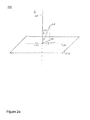
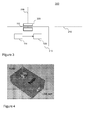
- Figure 1 is a block diagram illustrating schematically a system 100, comprising a first embodiment of the user interface according to the invention. It will be convenient to describe the operation of the device with the aid of a number of reference elements. These reference elements are virtual elements which do not correspond with actual physical elements, although they may be associated to various elements of the embodiments of the invention.
- the reference elements are illustrated in Figures 2a and 2b .
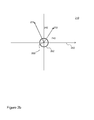
- Figure 2a shows a three dimensional view of the reference elements, whereas figure 2b shows a top view of the reference plane 210.
- the first embodiment shown in figure 1 comprises a joystick 100.
- Joystick 110 may be any type of joystick as long as it is configured for sensing data from which a direction of tilt of a component may be determined.
- joystick 100 may be a digital joystick, e.g., a four-button type joystick.
- joystick 100 is an optical joystick.
- the joystick comprises a movable component 112.
- component 112 may comprise a stick, protruding away from joystick 110. It is preferred if component 112 comprises a knob having a flat surface.
- Figure 1 schematically shows such a knob.
- the knob has a diameter between 1 and 2 cm, corresponding to the size of a human thumb.
- the knob is circular.
- the knob is smooth.
- the knob may have a metallic surface.
- component 112 is not freely movable but is constrained in that it tilts with respect to a spherical joint, acting as a pivot point.
- the spherical joint may be virtual.
- component 112 may also be rotatable around an axis. Typically, the spherical joint would lie on the axis.
- the user interface according to the invention enables a rotational type of input device, it is not necessary for component 112 to actually be rotatable. It is sufficient for the user to make a rotating movement over component 112.
- a user of joystick 110 may move component 112 within the boundaries allowed by component 112 constraints.
- the movement of component 112 is sensed by a sensor 114.
- a sensor 114 One possibility is that analogue sensors arranged along two axes sense the movement of component 112.
- component 112 reflects light coming from sensor 114, the reflection being representative for the movement.
- sensor 114 is an analogue sensor, i.e., sensitive for all directions.
- Sensor 114 may forward a first signal indicating the direction in which component 112 is moved with respect to reference axis 220 and a second signal indicating the magnitude of the direction. However, sensor 114 may also indicate the movement of component 112 using Cartesian coordinates, indicating the how far a virtual point of reference axis 220 would move from an origin 250.
- Joystick 110 further comprises a difference determination device 120.
- Difference determination device 120 is arranged to convert the tilting of component 112 as sensed by sensor 114 into a relative amount indicating how far the tilt has shifted. For example, difference determination device 120 may detect the onset of tilting, by receiving a signal from component 112, and then record the current tilt of component 112. When component 112 returns to a neutral position difference determination device 120 may conclude that the shift in direction has ended, and record a second tilt. From the two tilt position the difference in direction may be determined.
- difference determination device 120 can track the movement of the tilt by tracking the sensing at regular sampling intervals, and determine if the amount of shift has increased at least by a pre-determined amount.
- difference determination device 120 could verify if the magnitude of tilt remains over a pre-determined lower bound and/or under a pre-determined upper bound. If the magnitude is between the pre-determined lower bound and the predetermined upper bound, this indicates that the user makes a smooth and defined rotating movement. In one embodiment, these two controls (regular sampling and bounds) are combined.
- Parameter modifier 130 is shown here as part of a data processing system 140.
- Data processing system 140 may execute an application, some aspect of the application being under the control of the parameter.
- the parameter may be stored in a storage, e.g. a memory or a register, of data processing system 140, and parameter modifier 130 may comprise computer program code to alter the content of the storage.
- the storage could be an I/O port and parameter modifier 130 may comprise hardware means to alter it.
- the parameter also influences an output device output device 150, e.g. a display, connected to data processing system 140.
- output device 150 may show a display of a rotary knob which is turned in correspondence with the turning movement data obtained from joystick 110.
- parameter modifier 130 may multiply an angle difference obtained by difference determination device 120 with a pre-determined constant and add the result to the parameter.
- the angle difference may be signed indicating the direction of turning, thus an addition may result in decreasing the parameter.
- Component 112 has associated with it a reference plane reference plane 210. If component 112 is a flat knob, reference plane 210 is typically parallel with the flat surface. Component 112 has associated a reference axis reference axis 220 orthogonal to reference plane 210. If component 112 has comprises a stick, then typically, reference axis 220 is incident with reference axis 220 and optionally substantially parallel with the stick.
- Figure 2a and 2b show an origin 250 representing a pivot of component 112.
- the component 112 is tilted around origin 250.
- a (virtual) point on component 112 (say the intersection of reference axis 220 and component 112) is moved to a point 270.
- the vector from origin 250 to point 270 is representative of the tilt of component 112; we will refer to the vector from origin 250 to point 270 as tilt 270.
- the orthogonal projection of tilt 270 is a direction lying in the reference plane indicated with 272.
- the vector from origin 250 to direction 272 is representative both for the direction of the tilt of component 112 and for the magnitude.
- the figure shows a further reference axis 260 lying in the reference plane 210.
- Further reference axis 260 may be used to indicate the direction 272 as an angle.
- Angle 240 between axis 260 and direction 272 is representative for the direction, e.g., as the angular coordinate. If needed the distance from origin 250 to direction 272 may be determined to obtain a radial coordinate. Alternatively, an angle 230 between axis 230 and tilt 270 may be determined to represent the magnitude of tilt 270.
- Axis 260 is oriented, as is indicated in Figure 2b with an arrow.
- the magnitude may be used in an embodiment to ignore shifts bellow a certain threshold. It may happen that the sensitivity of the joystick is too large for casual use. By treating tilt with a small magnitude as if component 112 were in a neutral position the ease of use is increased.
- the threshold 250 is indicated as a circle in Figure 2b , tilt for which the projection on the reference plane lies within the circle may be ignored.
- direction 272 as a first direction lying the reference plane of a first tilt 270 at a particular sampling moment.
- component 112 is tilted into a second tilt, which corresponds to a second direction lying 274 in the reference plane.
- the second tilt was not drawn in Figure 2a but what has been said about tilt 270 applies mutatis mutandis to the second tilt.
- the projection of the second tilt is drawn in Figure 2b as direction 274.
- the angle between axis 260 and direction 274 is indicated with reference numeral 242.
- angle 240 By computing angle 240 minus angle 242, a difference in direction between the first direction lying in the reference plane of the first tilt at a particular sampling moment and the second direction lying in the reference plane of a second tilt assumed at the succeeding one of the sampling moments is determined.
- Parameter modifier 130 may determine the start and end of a rotation input in various ways.
- parameter modifier 130 may take two subsequent sampling moments on which component 112 is tilted as the first and second tilt. In this way parameter modifier 130 will detect and report small changes in tilt. The receiving application in data processing system 140 can accumulate the changes if this is required by the context.
- parameter modifier 130 may detect a first sampling moment at which component 112 is tilted from a natural position. Next parameter modifier 130 may monitor each subsequent sampling moment, and determine when the sign of the difference in direction changes between two subsequent sampling moment changes. The last sampling moment that gives no sign change is taken as the second tilt. In this way larger differences in direction are reported, but the rate at which these differences are reported various as they depend on the user input.
- Parameter modifier 130 may be integrated in joystick 110. This has the advantage that joystick 110 can directly report rotation information, i.e. differences in direction, to data processing system 140. As a result special hardware or software to accommodate parameter modifier 130 in data processing system 140 is avoided. This allows joystick 110 to be compatible with a wider range of data processing systems.
- a joystick can returns the tilted position it is in.
- a common format uses the (X,Y) coordinates.
- a position is represented by a vector of two dimension (usually X and Y). Converting such a vector to an angle is a basic trigonometric subject. For example, taking the X axis, orientated towards increasing coordinates as a further reference axis, an angle with the further reference axis may be computed by arctan(y/x).
- FIG 3 shows a joystick 310, which may be used in combination with data processing system 140 and/or output device 150.
- Joystick 310 is the same as joystick 110 except that component 112 comprises a wheel 320.
- Wheel 320 has been attached to component 112 as a pivot.
- the rotation axis of wheel 320 may coincide with reference axis 220.
- component 112 is arranged sunken in joystick 110 so that only wheel 320 extends outside of joystick 110.
- a first mode of input the joystick is tilted in the same way as joystick 110, and used as a pointing device; a tilt of component 112 is converted to coordinates such as Cartesian coordinates or polar coordinates, data processing system 140 uses the coordinates to move a pointer.
- the coordinates may be converted to a planar vector which may be added to location coordinates of the pointer, followed by a re-rendering of the pointer.
- the user may give commands to data processing system 140, such as pointing commands accompanied by a context sensitive event, say a button pressed.
- Joystick 310 and 110 however also have a second mode of input.
- In the second mode of input rotation information is passed to data processing system 140.
- Data processing system 140 may use the rotation information to control an application, for example by modifying a parameter, such as adding or subtracting to a parameter.
- joystick 310 it will seem to the user that the joystick comprises two sensors, one for sensing the tilt of component 112, the other one for measuring the amount of rotation of wheel 320.
- joystick 310 only has sensor 114.
- the rotation of wheel 320 is determined indirectly in the same way as in joystick 110. The wheel makes it easier for the user to give his rotation input, but does not in itself play a role in its measurement.
- a difference in direction device may report information related to both types of mode to the data processing system.
- the component is pivotally movable with respect to a pivot point.
- the pivot point is origin 250.
- axis 220 coincides with a centerline of the component while it is in the neutral position, after a tilt of the component the centerline of the component still intersects origin 250; for example, in an embodiment vector 270 could be seen as the new centerline after a tilt. During and after the tilt the component thus remains in the same orientation with respect to the pivot point.
- the joystick and component are arranged with respect to each other that rotation around one pivot point is the only movement that the component can make.
- the centerline may be orthogonal to the component. Instead of a centerline another axis associated with the component may be used.
- the movement of the component may be extended in various ways. For example, one could be extended it with a clicking movement, of the component towards the origin for indicating an event by the user to the user-interface.
- the component may be taken as the reflecting unit in Figure 2 of WO 2010/035170 and arranged in the joystick as described in the corresponding text; or as mirror 15 in Figure 2 of WO2009/125360 and arranged in the joystick as described in the corresponding text.
- the reflecting element or mirror could also be mechanically coupled to the component for passing the movement of the component to the sensor 114.
- the component is also configured for a rotating movement with respect to an axis of the component, e.g., a centerline, for example by attaching a wheel to component.
- Figure 4 shows prototype of joystick 110. Visible is a closed box having a top surface out of which a knob protrudes. The knob has a flat surface. Also visible is a connector for connecting the joystick to data processing system 140. In this case a USB connection is used, but other types of electronic computer connections are also possible, such as, Ethernet, Wi-Fi, etc.
- the protocol for sending commands from joystick 110 or 310 to data processing system 140 may vary, apart from the USB protocol, a proprietary protocol, XML etc may be used.
- Figure 5 illustrates at the left the mode of operating joystick 110 and 310.
- a finger typically a thumb is slided, or rubbed, across the top of component 112 in a circular motion.
- component 112 is tilted first in a first position, which shifts to a second position.
- the difference between the direction in which component 112 is first tilted and in which component 112 is last tilted determines the amount of rotation that the user input to the user interface.
- the user interface may use this input in a variety of ways.
- Figure 5 shows at the right a dial which moves in response to the difference in direction determined by parameter modifier 130. In one embodiment, a difference in direction of a particular angle results in a displayed rotation of the dial of the same particular angle.
- the displayed angle may differ from the particular angle.
- the particular angle may be multiplied with a factor to obtain the displayed angle.
- the factor may be a predetermined angle, but the factor may also depend on the speed with which the user moves from the first direction to the second direction.
- the difference in direction does not necessarily result in a change in a display; for example, the difference in direction may result in a change in a parameter which indicates the volume, as a result of which the volume changes. Furthermore, there is no reason to limit the display of the difference in direction to a dial; other possibilities include a sliding control, a scroll bar, etc.
- FIG. 6 shows a mobile phone 600 having a joystick 601 according to the invention.
- Mobile phone 600 is configured to obtain input of joystick 601 in the two modes.
- the second mode in which rotation input is received may be used to modify a parameter. For example, to control a scroll bar, modify a volume, change a display brightness, etc.
- An embodiment of a method of obtaining input for a data processing system comprises a sequence of steps.
- a tilt of a pivotally movable component of a joystick is sensed.
- the tilt may, for example, be measured with respect to a virtual reference axis and a virtual reference plane associated with the component.
- the component is tilted by being inclined away from the reference axis into a direction lying in the reference plane.
- a difference in direction between the direction of a first tilt at a particular sampling moment and the direction of a second tilt assumed at a succeeding one of the sampling moments is determined.
- the method also comprises a third step of modifying a parameter value of a parameter of the data processing system by adding or subtracting a difference value, the difference value depending upon the difference in direction.
- a method according to the invention may be executed using software, which comprises instructions for causing a processor system to perform this method.
- Software may only include those steps taken by a particular sub-entity of the system.
- the software may be stored in a suitable storage medium, such as a hard disk, a floppy, a memory etc.
- the software may be sent as a signal along a wire, or wireless, or using a data network, e.g., the Internet.
- the software may be made available for download and/or for remote usage on a server.
- the invention also extends to computer programs, particularly computer programs on or in a carrier, adapted for putting the invention into practice.
- the program may be in the form of source code, object code, a code intermediate source and object code such as partially compiled form, or in any other form suitable for use in the implementation of the method according to the invention.
- a program may have many different architectural designs.
- a program code implementing the functionality of the method or system according to the invention may be subdivided into one or more subroutines. Many different ways to distribute the functionality among these subroutines will be apparent to the skilled person.
- the subroutines may be stored together in one executable file to form a self-contained program.
- Such an executable file may comprise computer executable instructions, for example, processor instructions and/or interpreter instructions (e.g. Java interpreter instructions).
- one or more or all of the subroutines may be stored in at least one external library file and linked with a main program either statically or dynamically, e.g. at run-time.
- the main program contains at least one call to at least one of the subroutines.
- the subroutines may comprise function calls to each other.
- An embodiment relating to a computer program product comprises computer executable instructions corresponding to each of the processing steps of at least one of the methods set forth. These instructions may be subdivided into subroutines and/or be stored in one or more files that may be linked statically or dynamically.
- Another embodiment relating to a computer program product comprises computer executable instructions corresponding to each of the means of at least one of the systems and/or products set forth. These instructions may be subdivided into subroutines and/or be stored in one or more files that may be linked statically or dynamically.
- the carrier of a computer program may be any entity or device capable of carrying the program.
- the carrier may include a storage medium, such as a RAM, a ROM, for example a CD ROM or a semiconductor ROM, or a magnetic recording medium, for example a floppy disc or hard disk.
- the carrier may be a transmissible carrier such as an electrical or optical signal, which may be conveyed via electrical or optical cable or by radio or other means.
- the carrier may be constituted by such cable or other device or means.
- the carrier may be an integrated circuit in which the program is embedded, the integrated circuit being adapted for performing, or for use in the performance of, the relevant method.
Priority Applications (4)
| Application Number | Priority Date | Filing Date | Title |
|---|---|---|---|
| EP10188213A EP2450776A1 (de) | 2010-10-20 | 2010-10-20 | Benutzerschnittstelle zur Steuerung eines Datenverarbeitungssystems mit einem Joystick |
| KR1020110106950A KR20120041137A (ko) | 2010-10-20 | 2011-10-19 | 데이터 프로세싱 시스템용 사용자 인터페이스, 조이스틱, 데이터 프로세싱 시스템에 대한 입력 획득 방법 및 컴퓨터 판독가능 저장 매체 |
| CN2011103175485A CN102455802A (zh) | 2010-10-20 | 2011-10-19 | 使用操纵杆来控制数据处理系统的用户接口 |
| US13/276,347 US9019206B2 (en) | 2010-10-20 | 2011-10-19 | User-interface for controlling a data processing system using a joystick |
Applications Claiming Priority (1)
| Application Number | Priority Date | Filing Date | Title |
|---|---|---|---|
| EP10188213A EP2450776A1 (de) | 2010-10-20 | 2010-10-20 | Benutzerschnittstelle zur Steuerung eines Datenverarbeitungssystems mit einem Joystick |
Publications (1)
| Publication Number | Publication Date |
|---|---|
| EP2450776A1 true EP2450776A1 (de) | 2012-05-09 |
Family
ID=43719553
Family Applications (1)
| Application Number | Title | Priority Date | Filing Date |
|---|---|---|---|
| EP10188213A Withdrawn EP2450776A1 (de) | 2010-10-20 | 2010-10-20 | Benutzerschnittstelle zur Steuerung eines Datenverarbeitungssystems mit einem Joystick |
Country Status (4)
| Country | Link |
|---|---|
| US (1) | US9019206B2 (de) |
| EP (1) | EP2450776A1 (de) |
| KR (1) | KR20120041137A (de) |
| CN (1) | CN102455802A (de) |
Cited By (2)
| Publication number | Priority date | Publication date | Assignee | Title |
|---|---|---|---|---|
| EP3285148A1 (de) | 2016-08-19 | 2018-02-21 | Bigben Interactive SA | Verfahren zur kontrolle eines anzeigeelements über eine spielkonsole |
| EP3444016A1 (de) | 2017-08-17 | 2019-02-20 | Bigben Interactive SA | Verfahren zur kontrolle eines anzeigeelements mithilfe einer spielkonsole |
Families Citing this family (2)
| Publication number | Priority date | Publication date | Assignee | Title |
|---|---|---|---|---|
| JP6104606B2 (ja) * | 2013-01-08 | 2017-03-29 | 株式会社ミツトヨ | 三次元測定装置、入力方法及びプログラム |
| US10521030B2 (en) * | 2018-01-10 | 2019-12-31 | Microsoft Technology Licensing, Llc | Transforming a control stick movement space |
Citations (4)
| Publication number | Priority date | Publication date | Assignee | Title |
|---|---|---|---|---|
| US20080087476A1 (en) * | 2006-10-11 | 2008-04-17 | Apple Inc. | Sensor configurations in a user input device |
| WO2009125360A2 (en) | 2008-04-08 | 2009-10-15 | Nxp B.V. | Optical pointing device |
| WO2010020906A1 (en) | 2008-08-21 | 2010-02-25 | Nxp B.V. | Method and device for processing signals from a pointing device |
| WO2010035170A1 (en) | 2008-09-23 | 2010-04-01 | Nxp B.V. | Detection system for the detection of movements of a movable object, a method of detecting movements of a movable object, and an ic having implemented therein the detection system |
Family Cites Families (5)
| Publication number | Priority date | Publication date | Assignee | Title |
|---|---|---|---|---|
| CN1237562C (zh) * | 2000-02-10 | 2006-01-18 | 阿尔卑斯电气株式会社 | 两级按钮开关 |
| JP4344639B2 (ja) * | 2003-04-11 | 2009-10-14 | 日本航空電子工業株式会社 | 押圧操作型スイッチユニット |
| US7499040B2 (en) | 2003-08-18 | 2009-03-03 | Apple Inc. | Movable touch pad with added functionality |
| CN101641663B (zh) * | 2007-06-18 | 2015-03-18 | 苹果公司 | 用户输入装置中的传感器结构 |
| US8395111B2 (en) | 2010-03-31 | 2013-03-12 | Nxp B.V. | Optical system and method for detecting rotation of an object |
-
2010
- 2010-10-20 EP EP10188213A patent/EP2450776A1/de not_active Withdrawn
-
2011
- 2011-10-19 US US13/276,347 patent/US9019206B2/en not_active Expired - Fee Related
- 2011-10-19 CN CN2011103175485A patent/CN102455802A/zh active Pending
- 2011-10-19 KR KR1020110106950A patent/KR20120041137A/ko not_active Application Discontinuation
Patent Citations (4)
| Publication number | Priority date | Publication date | Assignee | Title |
|---|---|---|---|---|
| US20080087476A1 (en) * | 2006-10-11 | 2008-04-17 | Apple Inc. | Sensor configurations in a user input device |
| WO2009125360A2 (en) | 2008-04-08 | 2009-10-15 | Nxp B.V. | Optical pointing device |
| WO2010020906A1 (en) | 2008-08-21 | 2010-02-25 | Nxp B.V. | Method and device for processing signals from a pointing device |
| WO2010035170A1 (en) | 2008-09-23 | 2010-04-01 | Nxp B.V. | Detection system for the detection of movements of a movable object, a method of detecting movements of a movable object, and an ic having implemented therein the detection system |
Cited By (6)
| Publication number | Priority date | Publication date | Assignee | Title |
|---|---|---|---|---|
| EP3285148A1 (de) | 2016-08-19 | 2018-02-21 | Bigben Interactive SA | Verfahren zur kontrolle eines anzeigeelements über eine spielkonsole |
| WO2018033590A1 (fr) | 2016-08-19 | 2018-02-22 | Bigben Interactive | Procede de contrôle d'un element d'affichage par une console de jeux |
| RU2736167C2 (ru) * | 2016-08-19 | 2020-11-12 | Бигбен Интерэктив Са | Способ управления элементом отображения посредством консоли для игр |
| EP3444016A1 (de) | 2017-08-17 | 2019-02-20 | Bigben Interactive SA | Verfahren zur kontrolle eines anzeigeelements mithilfe einer spielkonsole |
| WO2019034560A1 (fr) | 2017-08-17 | 2019-02-21 | Bigben Interactive | Procede de controle d'un element d'affichage par une console de jeux |
| US11077372B2 (en) | 2017-08-17 | 2021-08-03 | Nacon Sa | Method for controlling a display element by a games console |
Also Published As
| Publication number | Publication date |
|---|---|
| CN102455802A (zh) | 2012-05-16 |
| US9019206B2 (en) | 2015-04-28 |
| KR20120041137A (ko) | 2012-04-30 |
| US20120098747A1 (en) | 2012-04-26 |
Similar Documents
| Publication | Publication Date | Title |
|---|---|---|
| US20110037695A1 (en) | Ergonomic control unit for providing a pointing function | |
| US7466307B2 (en) | Closed-loop sensor on a solid-state object position detector | |
| US20070222746A1 (en) | Gestural input for navigation and manipulation in virtual space | |
| US9785258B2 (en) | Ambidextrous mouse | |
| US5936612A (en) | Computer input device and method for 3-D direct manipulation of graphic objects | |
| US9223422B2 (en) | Remote controller and display apparatus, control method thereof | |
| US20150193023A1 (en) | Devices for use with computers | |
| TWM368130U (en) | Apparatus for implementing multiple push buttons in a user input device | |
| US9019206B2 (en) | User-interface for controlling a data processing system using a joystick | |
| EP1993026A2 (de) | Vorrichtung, Verfahren und computerlesbares Medium zur Abbildung eines Grafiktabletts auf einer zugehörigen Anzeige | |
| EP2872973A1 (de) | Verbesserungen an vorrichtungen zur verwendung mit rechnern | |
| EP2538308A2 (de) | Bewegungsbasierte Steuerung von einer gesteuerten Vorrichtung | |
| EP2362302B1 (de) | Verfahren zur Steuerung von Bewegungen eines Objekts in einer dreidimensionalen virtuellen Umgebung | |
| CN112237736A (zh) | 使用触摸感应以使轨迹球表现得像操纵杆 | |
| US20060227129A1 (en) | Mobile communication terminal and method | |
| WO2010020986A2 (en) | An ergonomic control unit for providing a pointing function | |
| JP4411996B2 (ja) | 携帯機器およびジョグダイヤル入力装置 | |
| WO1998043194A2 (en) | Apparatus and methods for moving a cursor on a computer display and specifying parameters | |
| US11449158B2 (en) | Interactive, touch-sensitive user interface device | |
| US20200042085A1 (en) | Input device for a graphical user interface | |
| JP2005228043A5 (de) | ||
| US20150227279A1 (en) | Variable horizontal scrolling | |
| US20240103643A1 (en) | Input device | |
| KR20180006670A (ko) | 스마트폰에 내장된 마우스 볼의 회전을 감지하여 사용자 인터페이스를 조작하는 스마트폰 | |
| KR101219292B1 (ko) | 표시부를 구비한 핸드 헬드 기기 및 상기 표시부에 표시되는 객체를 탐색하는 방법 |
Legal Events
| Date | Code | Title | Description |
|---|---|---|---|
| PUAI | Public reference made under article 153(3) epc to a published international application that has entered the european phase |
Free format text: ORIGINAL CODE: 0009012 |
|
| AK | Designated contracting states |
Kind code of ref document: A1 Designated state(s): AL AT BE BG CH CY CZ DE DK EE ES FI FR GB GR HR HU IE IS IT LI LT LU LV MC MK MT NL NO PL PT RO RS SE SI SK SM TR |
|
| AX | Request for extension of the european patent |
Extension state: BA ME |
|
| 17P | Request for examination filed |
Effective date: 20121109 |
|
| 17Q | First examination report despatched |
Effective date: 20140319 |
|
| STAA | Information on the status of an ep patent application or granted ep patent |
Free format text: STATUS: THE APPLICATION IS DEEMED TO BE WITHDRAWN |
|
| 18D | Application deemed to be withdrawn |
Effective date: 20140930 |