EP2450714A2 - Test and measurement instrument with oscillator phase dejitter - Google Patents
Test and measurement instrument with oscillator phase dejitter Download PDFInfo
- Publication number
- EP2450714A2 EP2450714A2 EP11187853A EP11187853A EP2450714A2 EP 2450714 A2 EP2450714 A2 EP 2450714A2 EP 11187853 A EP11187853 A EP 11187853A EP 11187853 A EP11187853 A EP 11187853A EP 2450714 A2 EP2450714 A2 EP 2450714A2
- Authority
- EP
- European Patent Office
- Prior art keywords
- signal
- frequency
- phase
- digitized
- shifted
- Prior art date
- Legal status (The legal status is an assumption and is not a legal conclusion. Google has not performed a legal analysis and makes no representation as to the accuracy of the status listed.)
- Withdrawn
Links
Images


Classifications
-
- G—PHYSICS
- G01—MEASURING; TESTING
- G01R—MEASURING ELECTRIC VARIABLES; MEASURING MAGNETIC VARIABLES
- G01R13/00—Arrangements for displaying electric variables or waveforms
- G01R13/02—Arrangements for displaying electric variables or waveforms for displaying measured electric variables in digital form
- G01R13/0218—Circuits therefor
- G01R13/0272—Circuits therefor for sampling
-
- H—ELECTRICITY
- H03—ELECTRONIC CIRCUITRY
- H03M—CODING; DECODING; CODE CONVERSION IN GENERAL
- H03M1/00—Analogue/digital conversion; Digital/analogue conversion
- H03M1/12—Analogue/digital converters
- H03M1/1205—Multiplexed conversion systems
- H03M1/121—Interleaved, i.e. using multiple converters or converter parts for one channel
Definitions
- This invention relates to test and measurement instruments and, more particularly, to test and measurement instruments with oscillator phase dejitter.
- Digital oscilloscopes have limited input bandwidths. Digitizers, amplifiers, and other components have limited bandwidths. Thus, a maximum input frequency of a sampled signal can be limited.
- an input signal can be split into multiple split signals. One split signal is digitized. Simultaneously, the other split signals are frequency shifted to a baseband frequency range that is within a digitizing bandwidth of the acquisition circuitry.
- a split signal can be frequency shifted by mixing the split signal with a periodic signal generated by an oscillator. The frequency shifted split signals can then be digitized. However, a phase shift relative to a trigger can be introduced by the respective periodic signals.
- the digitized frequency-shifted signals are frequency shifted to their original frequency range and then combined with the other digitized signals to create a representation of the input signal.
- the phase shifts introduced by the periodic signals can distort the reconstructed signal.
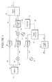
- FIGURE 1 is a block diagram of a test and measurement instrument with an all pass filter according to an embodiment of the invention.
- FIGURE 2 is a graph illustrating a phase shift between a trigger signal and a periodic signal.
- FIGURE 3 is a block diagram of frequency shifting circuit of a test and measurement instrument according to an embodiment of the invention.
- FIGURE 4 is a block diagram of another frequency shifting circuit of a test and measurement instrument according to an embodiment of the invention.
- FIGURE 5 is a block diagram of acquisition circuitry of a test and measurement instrument according to an embodiment of the invention.
- phase shift can be introduced into a digitized version of a frequency shifted input signal sub-band.
- This phase shift is a phase shift relative to a trigger signal.
- Each sub-band of the input signal within a split signal that is frequency shifted can have a different phase shift introduced relative to each other and the baseband sub-band.
- the sub-bands will have the phase shift.
- the phase shift can be compensated.
- FIGURE 1 is a block diagram of a test and measurement instrument with an all pass filter according to an embodiment of the invention.
- the test and measurement instrument includes a splitter 20.
- the splitter 20 is configured to split an input signal 40 into a plurality of split signals represented here by split signals 42 and 44.
- the splitter 20 can be a variety of splitters.
- the splitter 20 is a resistive power divider.
- the splitter 20 is configured to split the input signal 40 into split signals 42 and 44 such that the spectrums of the split signals 42 and 44 are substantially identical.
- Substantially identical includes variations caused by component variations.
- a splitter 20 may be designed to produce identical split signals 42 and 44; however, each split signal can be slightly different. Such split signals 42 and 44 are still considered substantially identical.
- the splitter 20 is configured to split the input signal 21 into split signals 42 and 44 having unequal spectrums.
- various frequency components of each split signal contribute to the reconstructed signal. However, for proper reconstruction, all of the frequency components can, but need not pass through each path.
- each split signal 42 and 44 needs only the frequency components of the input signal 40 that will be used from that split signal in the reconstructed signal. Accordingly, the splitter 20 can split the input signal 40 such that the split signals 42 and 44 have the desired spectrums.
- the input signal 40 can be split into any number of split signals.
- the splitter 20 can be configured to split the input signal 40 into four split signals, each associated with a different frequency sub-band.
- the two split signals 42 and 44 are used here merely as an example.
- the test and measurement instrument includes digitizers 26.
- each digitizer 26 can have a preamplifier, attenuators, filters, and/or other analog circuitry in the analog channel as needed.
- the input signals to the digitizers 26 can be amplified, attenuated, or otherwise filtered before digitization.
- the digitizers 26 can be any variety of circuitry that can digitize a signal.
- the digitizers 26 can include circuitry such as track and hold circuits, A/D converters, de-multiplexer circuits as needed to sample the associated input signals.
- the split signal 42 can be digitized by digitizer 26 to generate the digitized split signal 62.
- this split signal 42 can be a baseband signal, i.e. it was not frequency shifted
- the digitized split signal 62 can represent the baseband component used by the signal combiner 38 to recombine the signals into the reconstructed signal 64.
- the split signal 44 is input to a mixer 24.
- An oscillator 22 is configured to generate a periodic signal 46 input to the mixer 24.
- the combination of the periodic signal 46 and the split signal 44 can generate the frequency shifted signal 48.
- the frequency shifted signal 48 can be digitized by digitizer 26.
- the digitizers 26 can be configured to sample the respective input signals at substantially the same time. However, due to the frequency shifting of the mixer 24 a phase shift is introduced into the frequency shifted signal 48.
- the periodic signal 46 generated by the oscillator 22 can be asynchronous with a trigger input 50 used to trigger an acquisition. As the periodic signal 46 may not be synchronized with the trigger signal 50, the relative phase of the periodic signal 46 to the trigger input 50 can change from trigger event to trigger event.
- FIGURE 2 is a graph illustrating a phase shift between a trigger signal and a periodic signal.
- a trigger signal 80 is illustrated with a trigger event 84.
- the trigger signal 80 can be a signal generated from a trigger input 50 as illustrated in FIGURE 1 .
- a periodic signal 82 is illustrated relative to the trigger signal 80.
- a reference point on the periodic signal 86 is offset from the trigger signal 80 by time 86. Although a particular time is illustrated, since the trigger signal 80 is not synchronous with the periodic signal 82, the time 86 can change for each different trigger event 84. Accordingly, the phase shift introduced into each split signal associated with the periodic signal 82 will be changing between triggered acquisitions.
- the frequency shifted signal 48 results in a digitized frequency shifted signal 56.
- the phase shift introduced by the periodic signal 46 is present in the digitized frequency shifted signal 56.
- appropriate processing of the digitized frequency shifted signal 56 can substantially remove the phase shift.
- the digitized frequency shifted signal 56 is mixed with a periodic signal represented by oscillator 30.
- the mixing can be performed by multiplication of the digitized signals in an appropriate processor.
- a digital signal processor DSP
- microprocessor microprocessor
- programmable logic device or other processing system with appropriate peripheral devices can implement the functionality of the above described and other components, such as the controller 57, the phase detector 34, the all pass filter 36, the signal combiner 38, or the like.
- each block can be implemented discretely. Any variation between complete integration to fully discrete components can be implemented.
- the mixer 28 can output a restored split signal 58 where the digitized frequency shifted signal 56 is substantially restored to its original frequency range as in split signal 44.
- the restored split signal 58 has the phase shift described above.
- the restored split signal 58 can be filtered by all pass filter 36.
- the all pass filter can have a phase response that is the opposite of the phase shift induced by the periodic signal 46.
- phase correction can be implemented in other ways.
- other filtering can be performed on the restored split signal 58 such as band pass filtering, spectral shaping filtering, or the like.
- the phase adjustment of the all pass filter 36 can be part of such other filtering.
- the all pass filter 36 can be part of the signal combiner 38.
- the phase correction can be implemented in other ways than filtering the restored split signal 58.
- the test and measurement instrument can include a trigger system 32.
- the trigger system 32 can be configured to generate a trigger signal 52 in response to a trigger input 50. As described above, phase shifts relative to the trigger signal 52 can be different for every acquisition period.
- the trigger signal 52 can be compared with the digitized periodic signal 54 to generate a phase signal 55 in the phase detector 34.
- any circuit that can measure a time or phase difference can be used as the phase detector 34.
- the phase detector 34 can be implemented as part of the controller 57 and/or other processing circuitry.
- the phase detector 34 can be similar to circuits that measure the time from the trigger to the sample clock. In contrast, in this application it is the time from the trigger to a reference point of the periodic signal, such as a rising zero crossing, that is measured.
- such circuits use constant current sources charging a capacitor in order to measure the required time interval.
- Other circuits could be devised to perform similar measurements to measure the time or phase.
- time and phase can be used as desired.
- the periodic signal 46 can be a substantially single frequency.
- a given time corresponds to a given phase.
- the phase detector 34 can be configured to measure a time between the trigger signal and the periodic signal and convert the time to the phase. Accordingly, the phase signal 55 and/or other representations of the difference in phase of the trigger signal 52 and the periodic signal 50 can be represented as time or phase.
- the controller 57 can be configured to adjust processing of the digitized frequency-shifted signal 56 in response to the phase signal 55.
- the controller 57 is configured to adjust the all pass filter 36 in response to the phase signal 55 using a control signal 59.
- the adjustment to the all pass filter 36 can be a recalculation of the filter equation.
- a set of multiple filters can be calculated in advance.
- the controller can be configured to select a filter in response to the phase.
- the controller can convert the phase 55 into an index into the set of filters.
- the index can be the control signal 59 used to select a filter for the all pass filter 36.
- the all pass filter 36 need not be recalculated each acquisition.
- FIGURE 3 is a block diagram of frequency shifting circuit of a test and measurement instrument according to an embodiment of the invention.
- the phase correction of a split signal can be accomplished in a variety of ways.
- the digitized frequency shifted signal 56 was restored to its substantially original frequency range by the mixer 28 and oscillator 30.
- the restored split signal 58 was then filtered to correct the phase.
- an all pass filter 100 can be configured to filter the digitized frequency shifted signal 56 to generate a filtered frequency shifted signal 102. That is, the phase error can be corrected in the path followed by the particular split signal before the signal is restored to its original frequency range.
- the all pass filter 100 can be a part of other filtering, can be responsive to a control signal 59 from a controller 57, can be an index of precalculated filters, or the like.
- FIGURE 4 is a block diagram of another frequency shifting circuit of a test and measurement instrument according to an embodiment of the invention.
- the digitized frequency shifted signal 56 need not be filtered by an all pass filter as described above.
- the phase correction can be introduced into the periodic signal mixed with the digitized frequency shifted signal 56 in the mixer 28.
- a filter 120 can be used to filter the periodic signal from the mixer 30.
- the filter 120 can be an all pass filter, in this embodiment, the filter can be a more narrow filter with an amplitude response that not 1 at all frequencies. That is, since the periodic signal occupies a substantially narrow frequency range, a similarly narrow filter can be used.
- a compensating phase shift can be introduced into the digitized frequency shifted signal 56 when restored to its substantially original frequency range.
- the generation of the periodic signal itself in the oscillator 30 can be adjusted so that the relative phase has the desired phase offset. That is, in an embodiment, the oscillator 30 can be a digital oscillator generated by a function. A phase offset can be introduced into that function from acquisition to acquisition.
- the phase correction can be implemented in a variety of ways.
- the phase correction can be adjusted from acquisition to acquisition.
- a trigger input 50 can be asynchronous with an oscillator 22 resulting in the phase offset between the two varying from acquisition to acquisition, the varying phase offset can be compensated, reducing jitter in the reconstructed signal 64.
- FIGURE 5 is a block diagram of acquisition circuitry of a test and measurement instrument according to an embodiment of the invention.
- the periodic signal 46 from the oscillator 22 was digitized and supplied to the phase detector 34.
- the phase information of the periodic signal 46 can be obtained in different ways.
- the split signal 44 is mixed with a periodic signal 134 in mixer 130.
- the periodic signal 132 can be generated by a frequency doubler 132. That is, the frequency of the periodic signal 46 is doubled to generate the periodic signal 134.
- the frequency of the doubled periodic signal 134 can be on a high frequency side of a desired sub-band in the split signal 44.
- a combiner 138 can combine the frequency shifted split signal 136 with the periodic signal 46.
- the combined signal 140 can then be digitized by digitizer 26.
- the resulting digitized frequency shifted split signal 142 can be used for multiple purposes. For example, the desired sub-band is present in the digitized frequency shifted split signal 142 and can be used accordingly.
- a signal that is synchronized with the periodic signal 134 used to frequency shift the split signal 44 is also present. Accordingly, the digitized frequency shifted split signal 142 can be filtered by a filter configured to substantially isolate the periodic signal 146 from the digitized frequency-shifted split signal 142. This substantially isolated signal can then be used in the phase detector 34 as described above.
- any other technique that can pass phase information about the periodic signal 46 into the instrument can be used by the controller 57 to adjust the processing of split signals.
- Another embodiment includes computer readable code embodied on a computer readable medium that when executed, causes the machine to perform any of the above-described operations.
- a computer is any device that can execute code. Microprocessors, programmable logic devices, multiprocessor systems, digital signal processors, personal computers, or the like are all examples of such a machine.
- the computer readable medium can be a tangible computer readable medium that is configured to store the computer readable code in a non-transitory manner.
- test and measurement instrument is an oscilloscope platform.
- Other examples of a digitizing platform include a spectrum analyzer, a logic analyzer, or the like. Any instrument with a goal of converting an analog waveform into a digital waveform represented by binary samples stored in memory can be implemented with an embodiment described herein.
Abstract
Description
- This invention relates to test and measurement instruments and, more particularly, to test and measurement instruments with oscillator phase dejitter.
- Digital oscilloscopes have limited input bandwidths. Digitizers, amplifiers, and other components have limited bandwidths. Thus, a maximum input frequency of a sampled signal can be limited. To increase the effective bandwidth, an input signal can be split into multiple split signals. One split signal is digitized. Simultaneously, the other split signals are frequency shifted to a baseband frequency range that is within a digitizing bandwidth of the acquisition circuitry. A split signal can be frequency shifted by mixing the split signal with a periodic signal generated by an oscillator. The frequency shifted split signals can then be digitized. However, a phase shift relative to a trigger can be introduced by the respective periodic signals.
- The digitized frequency-shifted signals are frequency shifted to their original frequency range and then combined with the other digitized signals to create a representation of the input signal. The phase shifts introduced by the periodic signals can distort the reconstructed signal.
-
FIGURE 1 is a block diagram of a test and measurement instrument with an all pass filter according to an embodiment of the invention. -
FIGURE 2 is a graph illustrating a phase shift between a trigger signal and a periodic signal. -
FIGURE 3 is a block diagram of frequency shifting circuit of a test and measurement instrument according to an embodiment of the invention. -
FIGURE 4 is a block diagram of another frequency shifting circuit of a test and measurement instrument according to an embodiment of the invention. -
FIGURE 5 is a block diagram of acquisition circuitry of a test and measurement instrument according to an embodiment of the invention. - This disclosure describes embodiments of a test and measurement instrument using mixing with signal processing to reduce distortion during bandwidth multiplication. For example, as described above, a phase shift can be introduced into a digitized version of a frequency shifted input signal sub-band. This phase shift is a phase shift relative to a trigger signal. Each sub-band of the input signal within a split signal that is frequency shifted can have a different phase shift introduced relative to each other and the baseband sub-band. When recombined, the sub-bands will have the phase shift. As will be described in further detail below, the phase shift can be compensated.
-
FIGURE 1 is a block diagram of a test and measurement instrument with an all pass filter according to an embodiment of the invention. The test and measurement instrument includes asplitter 20. Thesplitter 20 is configured to split aninput signal 40 into a plurality of split signals represented here bysplit signals splitter 20 can be a variety of splitters. In one example, thesplitter 20 is a resistive power divider. - In an embodiment, the
splitter 20 is configured to split theinput signal 40 intosplit signals split signals splitter 20 may be designed to produceidentical split signals Such split signals - In another embodiment, the
splitter 20 is configured to split the input signal 21 intosplit signals split signal input signal 40 that will be used from that split signal in the reconstructed signal. Accordingly, thesplitter 20 can split theinput signal 40 such that thesplit signals - Although two
split signals input signal 40 can be split into any number of split signals. For example, thesplitter 20 can be configured to split theinput signal 40 into four split signals, each associated with a different frequency sub-band. The twosplit signals - The test and measurement instrument includes
digitizers 26. Although not illustrated, eachdigitizer 26 can have a preamplifier, attenuators, filters, and/or other analog circuitry in the analog channel as needed. Thus, the input signals to thedigitizers 26 can be amplified, attenuated, or otherwise filtered before digitization. In addition, thedigitizers 26 can be any variety of circuitry that can digitize a signal. For example, thedigitizers 26 can include circuitry such as track and hold circuits, A/D converters, de-multiplexer circuits as needed to sample the associated input signals. - In one path, the
split signal 42 can be digitized bydigitizer 26 to generate thedigitized split signal 62. As thissplit signal 42 can be a baseband signal, i.e. it was not frequency shifted, thedigitized split signal 62 can represent the baseband component used by the signal combiner 38 to recombine the signals into the reconstructedsignal 64. - In another path, the
split signal 44 is input to amixer 24. Anoscillator 22 is configured to generate aperiodic signal 46 input to themixer 24. The combination of theperiodic signal 46 and thesplit signal 44 can generate the frequency shiftedsignal 48. The frequency shiftedsignal 48 can be digitized bydigitizer 26. - In an embodiment, the
digitizers 26 can be configured to sample the respective input signals at substantially the same time. However, due to the frequency shifting of the mixer 24 a phase shift is introduced into the frequency shiftedsignal 48. In particular, theperiodic signal 46 generated by theoscillator 22 can be asynchronous with atrigger input 50 used to trigger an acquisition. As theperiodic signal 46 may not be synchronized with thetrigger signal 50, the relative phase of theperiodic signal 46 to thetrigger input 50 can change from trigger event to trigger event. -
FIGURE 2 is a graph illustrating a phase shift between a trigger signal and a periodic signal. Atrigger signal 80 is illustrated with atrigger event 84. As will be described in further detail below, thetrigger signal 80 can be a signal generated from atrigger input 50 as illustrated inFIGURE 1 . Aperiodic signal 82 is illustrated relative to thetrigger signal 80. A reference point on theperiodic signal 86 is offset from thetrigger signal 80 bytime 86. Although a particular time is illustrated, since thetrigger signal 80 is not synchronous with theperiodic signal 82, thetime 86 can change for eachdifferent trigger event 84. Accordingly, the phase shift introduced into each split signal associated with theperiodic signal 82 will be changing between triggered acquisitions. - Referring back to
FIGURE 1 , when digitized bydigitizer 26, the frequency shiftedsignal 48 results in a digitized frequency shiftedsignal 56. The phase shift introduced by theperiodic signal 46 is present in the digitized frequency shiftedsignal 56. However, appropriate processing of the digitized frequency shiftedsignal 56 can substantially remove the phase shift. - For example, in this embodiment, the digitized frequency shifted
signal 56 is mixed with a periodic signal represented byoscillator 30. As the signals here are digitized, the mixing can be performed by multiplication of the digitized signals in an appropriate processor. For example, a digital signal processor (DSP), microprocessor, programmable logic device, or other processing system with appropriate peripheral devices can implement the functionality of the above described and other components, such as thecontroller 57, the phase detector 34, the allpass filter 36, thesignal combiner 38, or the like. In other examples, each block can be implemented discretely. Any variation between complete integration to fully discrete components can be implemented. - The
mixer 28 can output a restoredsplit signal 58 where the digitized frequency shiftedsignal 56 is substantially restored to its original frequency range as insplit signal 44. In this example, the restoredsplit signal 58 has the phase shift described above. However, the restoredsplit signal 58 can be filtered by allpass filter 36. The all pass filter can have a phase response that is the opposite of the phase shift induced by theperiodic signal 46. Thus, when the output compensatedsplit signal 60 is input to thesignal combiner 38, the phase difference between the compensatedsplit signal 60 and the digitizedsplit signal 62 can be substantially eliminated. - Although an all
pass filter 36 has been described, the phase correction can be implemented in other ways. For example, other filtering can be performed on the restoredsplit signal 58 such as band pass filtering, spectral shaping filtering, or the like. The phase adjustment of the allpass filter 36 can be part of such other filtering. In another example, the allpass filter 36 can be part of thesignal combiner 38. As will be described in further detail below, the phase correction can be implemented in other ways than filtering the restoredsplit signal 58. - The test and measurement instrument can include a trigger system 32. The trigger system 32 can be configured to generate a
trigger signal 52 in response to atrigger input 50. As described above, phase shifts relative to thetrigger signal 52 can be different for every acquisition period. Thetrigger signal 52 can be compared with the digitizedperiodic signal 54 to generate aphase signal 55 in the phase detector 34. For example any circuit that can measure a time or phase difference can be used as the phase detector 34. In another embodiment, the phase detector 34 can be implemented as part of thecontroller 57 and/or other processing circuitry. - In another embodiment, the phase detector 34 can be similar to circuits that measure the time from the trigger to the sample clock. In contrast, in this application it is the time from the trigger to a reference point of the periodic signal, such as a rising zero crossing, that is measured. In one example, such circuits use constant current sources charging a capacitor in order to measure the required time interval. Other circuits could be devised to perform similar measurements to measure the time or phase.
- In an embodiment, time and phase can be used as desired. For example, the
periodic signal 46 can be a substantially single frequency. Thus, a given time corresponds to a given phase. The phase detector 34 can be configured to measure a time between the trigger signal and the periodic signal and convert the time to the phase. Accordingly, thephase signal 55 and/or other representations of the difference in phase of thetrigger signal 52 and theperiodic signal 50 can be represented as time or phase. - The
controller 57 can be configured to adjust processing of the digitized frequency-shiftedsignal 56 in response to thephase signal 55. In this example, thecontroller 57 is configured to adjust the allpass filter 36 in response to thephase signal 55 using acontrol signal 59. For example, the adjustment to the allpass filter 36 can be a recalculation of the filter equation. - In another example, a set of multiple filters can be calculated in advance. The controller can be configured to select a filter in response to the phase. For example, the controller can convert the
phase 55 into an index into the set of filters. The index can be thecontrol signal 59 used to select a filter for the allpass filter 36. Thus, the allpass filter 36 need not be recalculated each acquisition. -
FIGURE 3 is a block diagram of frequency shifting circuit of a test and measurement instrument according to an embodiment of the invention. The phase correction of a split signal can be accomplished in a variety of ways. InFIGURE 1 , the digitized frequency shiftedsignal 56 was restored to its substantially original frequency range by themixer 28 andoscillator 30. The restored splitsignal 58 was then filtered to correct the phase. - However, as illustrated in
FIGURE 3 , the processing of the digitized frequency shiftedsignal 56 can be different. In particular, an allpass filter 100 can be configured to filter the digitized frequency shiftedsignal 56 to generate a filtered frequency shiftedsignal 102. That is, the phase error can be corrected in the path followed by the particular split signal before the signal is restored to its original frequency range. Similar to the allpass filter 36 described above, the allpass filter 100 can be a part of other filtering, can be responsive to acontrol signal 59 from acontroller 57, can be an index of precalculated filters, or the like. -
FIGURE 4 is a block diagram of another frequency shifting circuit of a test and measurement instrument according to an embodiment of the invention. In this embodiment, the digitized frequency shiftedsignal 56 need not be filtered by an all pass filter as described above. In contrast, the phase correction can be introduced into the periodic signal mixed with the digitized frequency shiftedsignal 56 in themixer 28. - For example, a
filter 120 can be used to filter the periodic signal from themixer 30. Although thefilter 120 can be an all pass filter, in this embodiment, the filter can be a more narrow filter with an amplitude response that not 1 at all frequencies. That is, since the periodic signal occupies a substantially narrow frequency range, a similarly narrow filter can be used. By phase shifting the periodic signal from themixer 30, a compensating phase shift can be introduced into the digitized frequency shiftedsignal 56 when restored to its substantially original frequency range. - Although a filter has been described in a technique to shift the phase of a periodic signal from the
oscillator 30, other techniques can be used. For example, the generation of the periodic signal itself in theoscillator 30 can be adjusted so that the relative phase has the desired phase offset. That is, in an embodiment, theoscillator 30 can be a digital oscillator generated by a function. A phase offset can be introduced into that function from acquisition to acquisition. - Accordingly, the phase correction can be implemented in a variety of ways. In an embodiment, the phase correction can be adjusted from acquisition to acquisition. Thus, even though a
trigger input 50 can be asynchronous with anoscillator 22 resulting in the phase offset between the two varying from acquisition to acquisition, the varying phase offset can be compensated, reducing jitter in the reconstructedsignal 64. -
FIGURE 5 is a block diagram of acquisition circuitry of a test and measurement instrument according to an embodiment of the invention. InFIGURE 1 , theperiodic signal 46 from theoscillator 22 was digitized and supplied to the phase detector 34. As illustrated inFIGURE 5 , the phase information of theperiodic signal 46 can be obtained in different ways. - In an embodiment, the
split signal 44 is mixed with aperiodic signal 134 inmixer 130. However, theperiodic signal 132 can be generated by afrequency doubler 132. That is, the frequency of theperiodic signal 46 is doubled to generate theperiodic signal 134. In an embodiment, the frequency of the doubledperiodic signal 134 can be on a high frequency side of a desired sub-band in thesplit signal 44. - A
combiner 138 can combine the frequency shifted splitsignal 136 with theperiodic signal 46. The combinedsignal 140 can then be digitized bydigitizer 26. The resulting digitized frequency shifted split signal 142 can be used for multiple purposes. For example, the desired sub-band is present in the digitized frequency shifted splitsignal 142 and can be used accordingly. - In addition, a signal that is synchronized with the
periodic signal 134 used to frequency shift thesplit signal 44 is also present. Accordingly, the digitized frequency shifted split signal 142 can be filtered by a filter configured to substantially isolate theperiodic signal 146 from the digitized frequency-shiftedsplit signal 142. This substantially isolated signal can then be used in the phase detector 34 as described above. - Although digitizing the
periodic signal 46 and passing theperiodic signal 46 through a channel have been describe above, any other technique that can pass phase information about theperiodic signal 46 into the instrument can be used by thecontroller 57 to adjust the processing of split signals. - Another embodiment includes computer readable code embodied on a computer readable medium that when executed, causes the machine to perform any of the above-described operations. As used here, a computer is any device that can execute code. Microprocessors, programmable logic devices, multiprocessor systems, digital signal processors, personal computers, or the like are all examples of such a machine. In an embodiment, the computer readable medium can be a tangible computer readable medium that is configured to store the computer readable code in a non-transitory manner.
- An example of a test and measurement instrument is an oscilloscope platform. Other examples of a digitizing platform include a spectrum analyzer, a logic analyzer, or the like. Any instrument with a goal of converting an analog waveform into a digital waveform represented by binary samples stored in memory can be implemented with an embodiment described herein.
- Although particular embodiments have been described, it will be appreciated that the principles of the invention are not limited to those embodiments. Variations and modifications may be made without departing from the principles of the invention as set forth in the following claims.
Claims (15)
- A test and measurement instrument, comprising:an oscillator configured to generate a periodic signal;a mixer configured to mix an input signal with the periodic signal to generate a frequency-shifted signal;a trigger system configured to generate a trigger signal;a phase detector configured to sense a phase between the trigger signal and the periodic signal; anda controller configured to adjust processing of the frequency-shifted signal in response to the phase.
- The test and measurement instrument of claim 1, further comprising:a first digitizer configured to digitize the input signal; anda second digitizer configured to digitize the frequency-shifted signal;wherein the controller is configured to adjust processing of the digitized frequency-shifted signal before combination with the digitized input signal.
- The test and measurement instrument of claim 1, further comprising:a digitizer configured to digitize the periodic signal;wherein the phase detector is responsive to the digitized periodic signal.
- The test and measurement instrument of claim 1, further comprising:a digitizer configured to digitize the frequency-shifted signal; anda filter configured to substantially isolate the periodic signal from the digitized frequency-shifted signal;wherein the phase detector is responsive to the substantially isolated periodic signal.
- The test and measurement instrument of claim 1, wherein the phase detector is configured to:measure a time between the trigger signal and the periodic signal; andconvert the time to the phase.
- The test and measurement instrument of claim 1, wherein the controller is configured to:select a filter in response to the phase; andfilter the frequency-shifted signal in response to the selected filter.
- The test and measurement instrument of claim 1, further comprising:a digitizer configured to digitize the frequency-shifted signal;wherein the controller is configured to filter the digitized frequency-shifted signal in response to the phase.
- The test and measurement instrument of claim 1, further comprising:a digitizer configured to digitize the frequency-shifted signal;wherein the controller is configured to:frequency shift the digitized frequency-shifted signal to a substantially original frequency range to generate a digitized sub-band signal; andfilter the digitized sub-band signal in response to the phase.
- The test and measurement instrument of claim 1, further comprising:a digitizer configured to digitize the frequency-shifted signal;wherein the controller is configured to:frequency shift the digitized frequency-shifted signal to a substantially original frequency range to generate a digitized sub-band signal in response to a second periodic signal; andfilter the second periodic signal in response to the phase.
- The test and measurement instrument of claim 1, wherein the controller is configured to adjust processing of the frequency-shifted signal in response to the phase for each acquisition triggered by the trigger system.
- A method, comprising:mixing an input signal with a periodic signal to generate a frequency-shifted signal;generating a trigger signal;sensing a phase between the trigger signal and the periodic signal; andadjusting processing of the frequency-shifted signal in response to the phase.
- The method of claim 11, further comprising:digitizing the input signal; anddigitizing the frequency-shifted signal; andadjusting processing of the digitized frequency-shifted signal before combination with the digitized input signal.
- The method of claim 11, further comprising:digitizing the frequency-shifted signal;filtering the digitized frequency-shifted signal to substantially isolate the periodic signal from the digitized frequency-shifted signal; andsensing the phase between the trigger signal and the substantially isolated periodic signal.
- The method of claim 11, further comprising:selecting a filter in response to the phase; andfiltering the frequency-shifted signal in response to the selected filter.
- The method of claim 11, further comprising:digitizing the frequency-shifted signal;frequency shifting the digitized frequency-shifted signal to a substantially original frequency range to generate a digitized sub-band signal; andfiltering the digitized sub-band signal in response to the phase.
Applications Claiming Priority (1)
| Application Number | Priority Date | Filing Date | Title |
|---|---|---|---|
| US12/939,777 US20120112807A1 (en) | 2010-11-04 | 2010-11-04 | Test and measurement instrument with oscillator phase dejitter |
Publications (2)
| Publication Number | Publication Date |
|---|---|
| EP2450714A2 true EP2450714A2 (en) | 2012-05-09 |
| EP2450714A3 EP2450714A3 (en) | 2014-08-20 |
Family
ID=44925383
Family Applications (1)
| Application Number | Title | Priority Date | Filing Date |
|---|---|---|---|
| EP11187853.4A Withdrawn EP2450714A3 (en) | 2010-11-04 | 2011-11-04 | Test and measurement instrument with oscillator phase dejitter |
Country Status (4)
| Country | Link |
|---|---|
| US (1) | US20120112807A1 (en) |
| EP (1) | EP2450714A3 (en) |
| JP (1) | JP2012098277A (en) |
| CN (1) | CN102545893A (en) |
Families Citing this family (4)
| Publication number | Priority date | Publication date | Assignee | Title |
|---|---|---|---|---|
| US10659071B2 (en) | 2002-10-24 | 2020-05-19 | Teledyne Lecroy, Inc. | High bandwidth oscilloscope |
| US7219037B2 (en) | 2002-10-24 | 2007-05-15 | Lecroy Corporation | High bandwidth oscilloscope |
| US8891603B2 (en) * | 2012-06-25 | 2014-11-18 | Tektronix, Inc. | Re-sampling S-parameters for serial data link analysis |
| US9909907B2 (en) * | 2014-07-29 | 2018-03-06 | Tektronix, Inc. | Double quadrature with adaptive phase shift for improved phase reference performance |
Family Cites Families (9)
| Publication number | Priority date | Publication date | Assignee | Title |
|---|---|---|---|---|
| US7711510B2 (en) * | 2002-10-24 | 2010-05-04 | Lecroy Corporation | Method of crossover region phase correction when summing signals in multiple frequency bands |
| WO2004038432A2 (en) * | 2002-10-24 | 2004-05-06 | Lecroy Corporation | High bandwidth real time oscilloscope |
| US7957938B2 (en) * | 2002-10-24 | 2011-06-07 | Lecroy Corporation | Method and apparatus for a high bandwidth oscilloscope utilizing multiple channel digital bandwidth interleaving |
| US7219037B2 (en) * | 2002-10-24 | 2007-05-15 | Lecroy Corporation | High bandwidth oscilloscope |
| JP2008521014A (en) * | 2004-11-18 | 2008-06-19 | レクロイ コーポレーション | High bandwidth oscilloscope |
| JP4850473B2 (en) * | 2005-10-13 | 2012-01-11 | 富士通セミコンダクター株式会社 | Digital phase detector |
| US7474972B2 (en) * | 2007-03-23 | 2009-01-06 | Tektronix, Inc. | Bandwidth multiplication for a test and measurement instrument using non-periodic functions for mixing |
| CN100451667C (en) * | 2007-04-06 | 2009-01-14 | 中国科学院上海光学精密机械研究所 | Photoelectric heterodyne detection circuit |
| US20090093986A1 (en) * | 2007-10-04 | 2009-04-09 | Lecroy Corporation | Method and Apparatus for Elimination of Spurious Response due to Mixer Feed-Through |
-
2010
- 2010-11-04 US US12/939,777 patent/US20120112807A1/en not_active Abandoned
-
2011
- 2011-10-11 JP JP2011223875A patent/JP2012098277A/en active Pending
- 2011-11-04 CN CN2011103450849A patent/CN102545893A/en active Pending
- 2011-11-04 EP EP11187853.4A patent/EP2450714A3/en not_active Withdrawn
Non-Patent Citations (1)
| Title |
|---|
| None |
Also Published As
| Publication number | Publication date |
|---|---|
| EP2450714A3 (en) | 2014-08-20 |
| CN102545893A (en) | 2012-07-04 |
| US20120112807A1 (en) | 2012-05-10 |
| JP2012098277A (en) | 2012-05-24 |
Similar Documents
| Publication | Publication Date | Title |
|---|---|---|
| US7474972B2 (en) | Bandwidth multiplication for a test and measurement instrument using non-periodic functions for mixing | |
| US8742749B2 (en) | Test and measurement instrument including asynchronous time-interleaved digitizer using harmonic mixing | |
| US8588703B2 (en) | Arbitrary multiband overlay mixer apparatus and method for bandwidth multiplication | |
| US9030340B1 (en) | N-path interleaving analog-to-digital converter (ADC) with background calibration | |
| US9306590B2 (en) | Test and measurement instrument including asynchronous time-interleaved digitizer using harmonic mixing | |
| WO2006055935A2 (en) | High bandwidth oscilloscope | |
| US9859908B2 (en) | Test and measurement instrument including asynchronous time-interleaved digitizer using harmonic mixing and a linear time-periodic filter | |
| EP2916136B1 (en) | Test and measurement instrument including asynchronous time-interleaved digitizer using harmonic mixing | |
| EP2450714A2 (en) | Test and measurement instrument with oscillator phase dejitter | |
| JP6593983B2 (en) | Harmonic time interleaving system | |
| CN106018907B (en) | Frequency band overlapping separator | |
| CN106257300B (en) | Test and measurement instrument and method for determining a compensation value | |
| EP3507954B1 (en) | Time sequenced spectral stitching | |
| US9726702B2 (en) | Impedance measurement device and method | |
| US11050430B1 (en) | Sampling device | |
| Bhatta et al. | Time Domain Reconstruction of Incoherently Undersampled Periodic Waveforms Using Bandwidth Interleaving | |
| Moschitta et al. | Histogram-Based Techniques for ADC Testing |
Legal Events
| Date | Code | Title | Description |
|---|---|---|---|
| PUAI | Public reference made under article 153(3) epc to a published international application that has entered the european phase |
Free format text: ORIGINAL CODE: 0009012 |
|
| AK | Designated contracting states |
Kind code of ref document: A2 Designated state(s): AL AT BE BG CH CY CZ DE DK EE ES FI FR GB GR HR HU IE IS IT LI LT LU LV MC MK MT NL NO PL PT RO RS SE SI SK SM TR |
|
| AX | Request for extension of the european patent |
Extension state: BA ME |
|
| PUAL | Search report despatched |
Free format text: ORIGINAL CODE: 0009013 |
|
| AK | Designated contracting states |
Kind code of ref document: A3 Designated state(s): AL AT BE BG CH CY CZ DE DK EE ES FI FR GB GR HR HU IE IS IT LI LT LU LV MC MK MT NL NO PL PT RO RS SE SI SK SM TR |
|
| AX | Request for extension of the european patent |
Extension state: BA ME |
|
| RIC1 | Information provided on ipc code assigned before grant |
Ipc: G01R 13/02 20060101AFI20140715BHEP Ipc: H03M 1/12 20060101ALI20140715BHEP |
|
| STAA | Information on the status of an ep patent application or granted ep patent |
Free format text: STATUS: THE APPLICATION IS DEEMED TO BE WITHDRAWN |
|
| 18D | Application deemed to be withdrawn |
Effective date: 20150221 |