EP2450689A1 - Sample collecting method and sample collecting apparatus - Google Patents
Sample collecting method and sample collecting apparatus Download PDFInfo
- Publication number
- EP2450689A1 EP2450689A1 EP09846725A EP09846725A EP2450689A1 EP 2450689 A1 EP2450689 A1 EP 2450689A1 EP 09846725 A EP09846725 A EP 09846725A EP 09846725 A EP09846725 A EP 09846725A EP 2450689 A1 EP2450689 A1 EP 2450689A1
- Authority
- EP
- European Patent Office
- Prior art keywords
- sampling
- airflow
- blowing
- port
- sucking
- Prior art date
- Legal status (The legal status is an assumption and is not a legal conclusion. Google has not performed a legal analysis and makes no representation as to the accuracy of the status listed.)
- Granted
Links
Images

Classifications
-
- G—PHYSICS
- G01—MEASURING; TESTING
- G01N—INVESTIGATING OR ANALYSING MATERIALS BY DETERMINING THEIR CHEMICAL OR PHYSICAL PROPERTIES
- G01N1/00—Sampling; Preparing specimens for investigation
- G01N1/02—Devices for withdrawing samples
- G01N1/22—Devices for withdrawing samples in the gaseous state
-
- G—PHYSICS
- G01—MEASURING; TESTING
- G01N—INVESTIGATING OR ANALYSING MATERIALS BY DETERMINING THEIR CHEMICAL OR PHYSICAL PROPERTIES
- G01N1/00—Sampling; Preparing specimens for investigation
- G01N1/02—Devices for withdrawing samples
- G01N1/22—Devices for withdrawing samples in the gaseous state
- G01N1/24—Suction devices
-
- G—PHYSICS
- G01—MEASURING; TESTING
- G01N—INVESTIGATING OR ANALYSING MATERIALS BY DETERMINING THEIR CHEMICAL OR PHYSICAL PROPERTIES
- G01N1/00—Sampling; Preparing specimens for investigation
- G01N1/02—Devices for withdrawing samples
- G01N2001/022—Devices for withdrawing samples sampling for security purposes, e.g. contraband, warfare agents
-
- G—PHYSICS
- G01—MEASURING; TESTING
- G01N—INVESTIGATING OR ANALYSING MATERIALS BY DETERMINING THEIR CHEMICAL OR PHYSICAL PROPERTIES
- G01N1/00—Sampling; Preparing specimens for investigation
- G01N1/02—Devices for withdrawing samples
- G01N2001/028—Sampling from a surface, swabbing, vaporising
Definitions
- the present invention relates to detection of dangerous articles, such as narcotic drugs, explosives, chemical warfare agents, industry poisonous agents or the like, more particularly, to a sampling method and a sampling device for the above articles by sucking the same in a form of gaseous or particulate state into a detecting device.
- a suck-type sampling method sampling is performed by using a wiping paper to wipe the detecting surface, and then the wiping paper is moved directly into a detector.
- the present application is directed to the suck-type sampling method rather than the wipe-type sampling method.
- sampling is performed directly at the detecting surface by way of sucking, or is performed based on collected samples in advance by way of sucking.
- the first method is a direct suction method in which, as shown in Fig.1 , a detecting device sucks air directly from surrounding environment. Because some dangerous articles have viscosity, they tend to adhere to surfaces of an object to be detected. Thus, the direct suction method can only capture volatilized gases or fine particles in a free state.
- a second method is widely used, in which airflow is first blown to raise the particles of the sample; then, the raised particles are sucked into the detecting device, as shown in Fig. 2 .
- the blown airflow is formed of spiral or heated air.
- Fig. 2 shows an example of the second method which improves the detecting efficiency; usually, the airflow is blown from peripheral of a sampling device and is sucked at a center part thereof.
- the above method can be implemented more easily with a sampling device, wherein the inlet of a detecting device is commonly provided at the center part of the sampling device so that the detecting device can be connected directly with the sampling device.
- the blowing force of such sampling device is small, which results in a low sampling efficiency.
- the present invention is made to solve or alleviate at least one of the disadvantages or technical problems in the prior art.
- a sampling method comprising the steps of: blowing airflow towards a center portion of a sampling surface through a blowing port; and sucking the blown airflow from periphery of the sampling surface through a sucking port.
- a sampling method comprising the steps of: providing a sampling device on a sampling surface, the sampling device being shaped to form a sampling space together with the sampling surface, and the sampling device including a blowing port arranged at the center portion of the sampling device and a sucking port arranged at periphery of the sampling device; blowing airflow towards the sampling surface through the blowing port; and sucking the airflow blown towards the sampling surface through the sucking port so as to collect samples.
- the step of blowing airflow comprises increasing an instantaneous speed of the airflow from the blowing port by means of a volume buffer.
- the step of blowing airflow comprises heating the airflow.
- the step of blowing airflow comprises adjusting the blowing direction of the airflow from the blowing port with respect to the sampling surface.
- the adjusting of the blowing direction is performed by providing a spiral airflow guiding device or a fan within the blowing port.
- the blowing port is tapered to increase the speed of the airflow from the blowing port.
- the sucking port comprises a plurality of sucking ports
- the blowing port is arranged at a center portion of a polygon formed by the plurality of sucking ports.
- the sucking port forms a ring surrounding the periphery of the sampling device, and the blowing port is arranged at a center portion of the ring.
- blowing port extends in a direction which is perpendicular to the sampling surface.
- a sampling device which comprises: a blowing port which blows airflow towards a center portion of a sampling surface; and a sucking port which sucks the blown airflow from periphery of the sampling surface.
- a sampling device which comprises a housing which is shaped to form a sampling space together with a sampling surface; a blowing port which is provided at a center portion of the housing to blow airflow towards the sampling surface; and a sucking port which is provided at periphery of the housing to suck the airflow blown towards the sampling surface.
- the sampling device further comprises a volume buffer which is provided at the upstream of the blowing port in a flowing direction of the airflow to increase an instantaneous speed of the airflow from the blowing port.
- the sampling device further comprises a heater for heating the airflow.
- the sampling device further comprises a spiral airflow guiding device which is provided within the blowing port to adjust the blowing direction of the airflow from the blowing port with respect to the sampling surface.
- the sampling device further comprises a fan which is provided within the blowing port to adjust the blowing direction of the airflow from the blowing port with respect to the sampling surface.
- the blowing port is tapered to increase the speed of the airflow from the blowing port.
- the sucking port comprises a plurality of sucking ports
- the blowing port is arranged at a center portion of a polygon formed by the plurality of sucking ports.
- the sucking port forms a ring surrounding the periphery of the sampling device, and the blowing port is arranged at a center portion of the ring.
- the blowing port comprises a plurality of blowing ports.
- the blowing device is provided at the center, while the sucking device is provided at the periphery, which may produce the following technical effect.
- the present invention can provide a blowing airflow having a higher speed.
- the blown airflow is used to blow particles of dangerous articles off the detecting surface to which the particles may adhere.
- the center portion which is connected directly to the detecting device, can not provide a sucking airflow having a too large flow rate. Because the flow rate of the blowing airflow is larger than that of the sucking airflow, the particles raised by the blowing airflow supplied from the periphery can not be completely sucked into the detecting device. In addition, some particles raised by the blowing airflow supplied from the periphery may be away from the center portion and therefore it is very difficult to collect them.
- a sampling method comprises the steps of: blowing airflow towards a center portion of a sampling surface 5 through a blowing port 1, as shown by the arrow A; and sucking the blown airflow from periphery of the sampling surface 5 through a sucking port 2, as shown by the arrow B.
- another sampling method comprises the steps of: providing a sampling device 100 on a sampling surface 5, the sampling device 100 being shaped to form a sampling space S together with the sampling surface 5, and the sampling device 100 including a blowing port 1 arranged at the center portion of the sampling device 100 and a sucking port 2 arranged at periphery of the sampling device 100; blowing airflow towards the sampling surface through the blowing port, as shown by the arrow A; and sucking the airflow blown towards the sampling surface through the sucking port so as to collect samples, as shown by the arrow B.
- the blowing port 1 is communicated with a blowing air source (not shown) through an inlet 4, and the sucking port 2 is communicated with a detecting device (not shown) through an outlet 3.
- the step of blowing airflow comprises increasing an instantaneous speed of the airflow from the blowing port by means of a volume buffer (not shown) and/or the step of blowing airflow comprises heating the airflow.
- the volume buffer may be provided at the upstream of the blowing port 1, for example, when the air pressure in the volume buffer reaches a predetermined value, the air in the volume buffer is blown at a high speed towards the sampling surface 5 via the blowing port 5, then the volume buffer begins to re-accumulate air therein.
- the blowing airflow is intermittent; however, a high speed is obtained. If the blowing air is heated before blowing towards the sampling surface, the volatilization of the dangerous articles at the sampling surface is expedited or the adhering of the articles to the sampling surface is weakened, which results in an improved sampling precision.
- the step of blowing airflow comprises adjusting the blowing direction of the airflow from the blowing port 1 with respect to the sampling surface 5.
- the adjusting of the blowing direction is performed by providing a spiral airflow guiding device 7 (referring to Fig. 4 ) within the blowing port 1, or the adjusting of the blowing direction is performed by providing a fan (not shown) within the blowing port 1.
- the blowing airflow is swirled above the sampling surface 5 by using the spiral airflow guiding device 7 or the fan, so that the blowing ability of the airflow is enhanced.
- the blowing port 1 is tapered to increase the speed of the airflow from the blowing port 1.
- the blowing port 1 is formed as a nozzle.
- the sampling device 100 may comprise a plurality of sucking ports 2, and in this case the blowing port 1 can be arranged at a center portion of a polygon formed by the plurality of sucking ports.
- the sucking port 2 may form a ring surrounding the periphery of the sampling device 100, and the blowing port 1 is arranged at a center portion of the ring.
- the blowing port 1 may extend in a direction which is perpendicular to the sampling surface.
- a skirt portion 6 is provided at the periphery of the sampling device 100 to seal the sampling space S.
- a sampling device 100 comprises: a blowing port 1 which blows airflow towards a center portion of a sampling surface 5, referring to the arrow A; and a sucking port 2 which sucks the blown airflow from periphery of the sampling surface 5, referring to the arrow B.
- a sampling device 100 comprises a housing 10 which is shaped to form a sampling space S together with a sampling surface 5; a blowing port 1 which is provided at a center portion of the housing 10 to blow airflow towards the sampling surface, referring to the arrow A; and a sucking port 2 which is provided at periphery of the housing 10 to suck the airflow blown towards the sampling surface, referring to the arrow B.
- the blowing port 1 is communicated with a blowing air source (not shown) through an inlet 4, and the sucking port 2 is communicated with a detecting device (not shown) through an outlet 3.
- the above sampling devices 100 may further comprise a volume buffer (not shown) which is provided at the upstream of the blowing port 1 in a flowing direction of the airflow to increase an instantaneous speed of the airflow from the blowing port 1. For example, when the air pressure in the volume buffer reaches a predetermined value, the air in the volume buffer is blown at a high speed towards the sampling surface 5 via the blowing port 5, then the volume buffer begins to re-accumulate air therein. Thus, the blowing airflow is intermittent; however, a high speed is obtained.
- the above sampling devices 100 may further comprise a heater (not shown) for heating the airflow.
- the heater may be provided directly within the blowing port 1. If the blowing air is heated before blowing towards the sampling surface, the volatilization of the dangerous articles at the sampling surface is expedited or the adhering of the articles to the sampling surface is weakened, which results in an improved sampling precision.
- the above sampling devices 100 may further comprise a spiral airflow guiding device 7 (referring to Fig. 4 ) which is provided within the blowing port 1 to adjust the blowing direction of the airflow from the blowing port 1 with respect to the sampling surface 5.
- the above sampling devices 100 may further comprise a fan or other guiding member (not shown) which is provided within the blowing port 1 to adjust the blowing direction of the airflow from the blowing port 1 with respect to the sampling surface 5.
- the blowing airflow is swirled above the sampling surface 5 by using the spiral airflow guiding device 7 or the fan, so that the blowing ability of the airflow is enhanced.
- the blowing port 1 is tapered to increase the speed of the airflow from the blowing port 1.
- the blowing port 1 is formed as a nozzle.
- the sampling device 100 may comprise a plurality of blowing ports 1.
- the sampling device 100 may comprise a plurality of sucking ports 2, and in this case the blowing port 1 can be arranged at a center portion of a polygon formed by the plurality of sucking ports.
- the sucking port 2 may form a ring surrounding the periphery of the sampling device, and the blowing port 1 is arranged at a center portion of the ring.
- the blowing port 1 may extend in a direction which is perpendicular to the sampling surface.
- a skirt portion 6 is provided at the periphery of the sampling device 100 to seal the sampling space S.
Landscapes
- Health & Medical Sciences (AREA)
- Life Sciences & Earth Sciences (AREA)
- Engineering & Computer Science (AREA)
- Biomedical Technology (AREA)
- Molecular Biology (AREA)
- Physics & Mathematics (AREA)
- Chemical & Material Sciences (AREA)
- Analytical Chemistry (AREA)
- Biochemistry (AREA)
- General Health & Medical Sciences (AREA)
- General Physics & Mathematics (AREA)
- Immunology (AREA)
- Pathology (AREA)
- Sampling And Sample Adjustment (AREA)
Abstract
Description
- The present invention relates to detection of dangerous articles, such as narcotic drugs, explosives, chemical warfare agents, industry poisonous agents or the like, more particularly, to a sampling method and a sampling device for the above articles by sucking the same in a form of gaseous or particulate state into a detecting device.
- In the security inspection field, it is very important to detect dangerous articles, such as narcotic drugs, explosives, chemical warfare agents, industry poisonous agents. Therefore, various detectors for detecting the above articles have been developed. However, for each kind of detector, samples have to be transferred from a detecting surface of the article into the detector during detecting.
- At present, two methods of a suck-type sampling method and a wipe-type sampling method are commonly used. In the wipe-type sampling method, sampling is performed by using a wiping paper to wipe the detecting surface, and then the wiping paper is moved directly into a detector. However, the present application is directed to the suck-type sampling method rather than the wipe-type sampling method. In the suck-type sampling method, sampling is performed directly at the detecting surface by way of sucking, or is performed based on collected samples in advance by way of sucking.
- There are mainly two suck-type sampling methods used in existing products or disclosed by published patents. The first method is a direct suction method in which, as shown in
Fig.1 , a detecting device sucks air directly from surrounding environment. Because some dangerous articles have viscosity, they tend to adhere to surfaces of an object to be detected. Thus, the direct suction method can only capture volatilized gases or fine particles in a free state. In order to collect the dangerous articles adhered to the surfaces of the object to be detected, a second method is widely used, in which airflow is first blown to raise the particles of the sample; then, the raised particles are sucked into the detecting device, as shown inFig. 2 . Advantageously, the blown airflow is formed of spiral or heated air. -
Fig. 2 shows an example of the second method which improves the detecting efficiency; usually, the airflow is blown from peripheral of a sampling device and is sucked at a center part thereof. The above method can be implemented more easily with a sampling device, wherein the inlet of a detecting device is commonly provided at the center part of the sampling device so that the detecting device can be connected directly with the sampling device. However, because an air exit has a large size while the airflow is sucked at the center part, the blowing force of such sampling device is small, which results in a low sampling efficiency. - In view of the above, the present invention is made to solve or alleviate at least one of the disadvantages or technical problems in the prior art.
- According to an aspect of the present invention, there is provided a sampling method, comprising the steps of: blowing airflow towards a center portion of a sampling surface through a blowing port; and sucking the blown airflow from periphery of the sampling surface through a sucking port.
- According to another aspect of the present invention, there is provided a sampling method, comprising the steps of: providing a sampling device on a sampling surface, the sampling device being shaped to form a sampling space together with the sampling surface, and the sampling device including a blowing port arranged at the center portion of the sampling device and a sucking port arranged at periphery of the sampling device; blowing airflow towards the sampling surface through the blowing port; and sucking the airflow blown towards the sampling surface through the sucking port so as to collect samples.
- Alternatively, the step of blowing airflow comprises increasing an instantaneous speed of the airflow from the blowing port by means of a volume buffer.
- Alternatively, the step of blowing airflow comprises heating the airflow.
- Alternatively, the step of blowing airflow comprises adjusting the blowing direction of the airflow from the blowing port with respect to the sampling surface.
- Alternatively, the adjusting of the blowing direction is performed by providing a spiral airflow guiding device or a fan within the blowing port.
- Alternatively, the blowing port is tapered to increase the speed of the airflow from the blowing port.
- Alternatively, the sucking port comprises a plurality of sucking ports, and the blowing port is arranged at a center portion of a polygon formed by the plurality of sucking ports.
- Alternatively, the sucking port forms a ring surrounding the periphery of the sampling device, and the blowing port is arranged at a center portion of the ring.
- Alternatively, the blowing port extends in a direction which is perpendicular to the sampling surface.
- According to further another aspect of the present invention there is provided a sampling device which comprises: a blowing port which blows airflow towards a center portion of a sampling surface; and a sucking port which sucks the blown airflow from periphery of the sampling surface.
- According to still another aspect of the present invention, there is provided a sampling device which comprises a housing which is shaped to form a sampling space together with a sampling surface; a blowing port which is provided at a center portion of the housing to blow airflow towards the sampling surface; and a sucking port which is provided at periphery of the housing to suck the airflow blown towards the sampling surface.
- Alternatively, the sampling device further comprises a volume buffer which is provided at the upstream of the blowing port in a flowing direction of the airflow to increase an instantaneous speed of the airflow from the blowing port.
- Alternatively, the sampling device further comprises a heater for heating the airflow.
- Alternatively, the sampling device further comprises a spiral airflow guiding device which is provided within the blowing port to adjust the blowing direction of the airflow from the blowing port with respect to the sampling surface.
- Alternatively, the sampling device further comprises a fan which is provided within the blowing port to adjust the blowing direction of the airflow from the blowing port with respect to the sampling surface.
- Alternatively, the blowing port is tapered to increase the speed of the airflow from the blowing port.
- Alternatively, the sucking port comprises a plurality of sucking ports, and the blowing port is arranged at a center portion of a polygon formed by the plurality of sucking ports.
- Alternatively, the sucking port forms a ring surrounding the periphery of the sampling device, and the blowing port is arranged at a center portion of the ring.
- Alternatively, the blowing port comprises a plurality of blowing ports.
- According to the present invention, the blowing device is provided at the center, while the sucking device is provided at the periphery, which may produce the following technical effect.
- For the same flow rate, the smaller is the section area of the blowing port, the higher is the speed of the airflow. Thus, the area of the blowing port in the conventional solution where the airflow is blown at the periphery is larger than that of the blowing port in a solution where the airflow is blown at the center according to the present invention; therefore, the present invention can provide a blowing airflow having a higher speed. The blown airflow is used to blow particles of dangerous articles off the detecting surface to which the particles may adhere. According to aerodynamics principle, as for the same particle, blowing force F acting on it is calculated based on the following formula:

wherein parameters in the formula except for the speed v of the airflow are constant, thus, the blowing force F is in direct proportion to the square of v. Therefore, for the same flow rate of the airflow, the solution of the present invention will produce a larger blowing force, compared to the conventional solution. - In the conventional solution, since the area of the blowing port is large, a larger flow rate is needed in order to improve the blowing ability, however, the center portion, which is connected directly to the detecting device, can not provide a sucking airflow having a too large flow rate. Because the flow rate of the blowing airflow is larger than that of the sucking airflow, the particles raised by the blowing airflow supplied from the periphery can not be completely sucked into the detecting device. In addition, some particles raised by the blowing airflow supplied from the periphery may be away from the center portion and therefore it is very difficult to collect them.
- With the solution of the present invention in which the airflow is blown at the center portion, a blowing airflow having a higher speed is obtained with a lower flow rate of the blowing airflow, and at the same time, the raised particles move towards the periphery together with the airflow and are captured by the sucking device provided at the periphery, thus, the sampling efficiency is improved.
- The attached drawings of the present invention will be described below for more complete understanding of the present invention and showing of practicing the present invention, wherein
-
Fig. 1 is a schematic view of a direct air-suction method of the prior art; -
Fig. 2 is a schematic view showing an air passage solution of the prior art in which the air is blown from the periphery and is sucked in the center portion; -
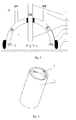
Fig. 3 is a schematic view showing an air passage solution according to one embodiment of the present invention in which the air is blown from the center portion while is sucked in the periphery; and -
Fig. 4 is a schematic view a spiral airflow guiding device according to one embodiment of the present invention. - Exemplary embodiments of the present disclosure will be described hereinafter in detail with reference to the attached drawings. The present disclosure may, however, be embodied in many different forms and should not be construed as being limited to the embodiment set forth herein; rather, these embodiments are provided so that the present disclosure will be thorough and complete, and will fully convey the concept of the disclosure to those skilled in the art.
- Refer to
Fig. 3 , a sampling method according to the present invention comprises the steps of: blowing airflow towards a center portion of a sampling surface 5 through a blowingport 1, as shown by the arrow A; and sucking the blown airflow from periphery of the sampling surface 5 through a suckingport 2, as shown by the arrow B. - Also refer to
Fig. 3 , another sampling method according to the present invention comprises the steps of: providing asampling device 100 on a sampling surface 5, thesampling device 100 being shaped to form a sampling space S together with the sampling surface 5, and thesampling device 100 including a blowingport 1 arranged at the center portion of thesampling device 100 and a suckingport 2 arranged at periphery of thesampling device 100; blowing airflow towards the sampling surface through the blowing port, as shown by the arrow A; and sucking the airflow blown towards the sampling surface through the sucking port so as to collect samples, as shown by the arrow B. - As known in the art, the blowing
port 1 is communicated with a blowing air source (not shown) through aninlet 4, and the suckingport 2 is communicated with a detecting device (not shown) through anoutlet 3. - In the above sampling methods, the step of blowing airflow comprises increasing an instantaneous speed of the airflow from the blowing port by means of a volume buffer (not shown) and/or the step of blowing airflow comprises heating the airflow. In an embodiment, the volume buffer may be provided at the upstream of the blowing
port 1, for example, when the air pressure in the volume buffer reaches a predetermined value, the air in the volume buffer is blown at a high speed towards the sampling surface 5 via the blowing port 5, then the volume buffer begins to re-accumulate air therein. Thus, the blowing airflow is intermittent; however, a high speed is obtained. If the blowing air is heated before blowing towards the sampling surface, the volatilization of the dangerous articles at the sampling surface is expedited or the adhering of the articles to the sampling surface is weakened, which results in an improved sampling precision. - In the above sampling methods, the step of blowing airflow comprises adjusting the blowing direction of the airflow from the blowing
port 1 with respect to the sampling surface 5. Advantageously, the adjusting of the blowing direction is performed by providing a spiral airflow guiding device 7 (referring toFig. 4 ) within the blowingport 1, or the adjusting of the blowing direction is performed by providing a fan (not shown) within the blowingport 1. For example, the blowing airflow is swirled above the sampling surface 5 by using the spiralairflow guiding device 7 or the fan, so that the blowing ability of the airflow is enhanced. - Advantageously, the blowing
port 1 is tapered to increase the speed of the airflow from the blowingport 1. For instance, the blowingport 1 is formed as a nozzle. - Next, the arrangement of the sucking
port 2 will be described. Thesampling device 100 may comprise a plurality of suckingports 2, and in this case the blowingport 1 can be arranged at a center portion of a polygon formed by the plurality of sucking ports. Alternatively, the suckingport 2 may form a ring surrounding the periphery of thesampling device 100, and the blowingport 1 is arranged at a center portion of the ring. - In addition, in order to improve the disturbance ability of the blowing airflow to the samples on the sampling surface 5, the blowing
port 1 may extend in a direction which is perpendicular to the sampling surface. - In order to improve the sucking efficiency, for example, to prevent or restrict receiving air outside of the sampling device, a
skirt portion 6 is provided at the periphery of thesampling device 100 to seal the sampling space S. - Refer to
Fig. 3 , asampling device 100 according to one embodiment of the present invention comprises: a blowingport 1 which blows airflow towards a center portion of a sampling surface 5, referring to the arrow A; and a suckingport 2 which sucks the blown airflow from periphery of the sampling surface 5, referring to the arrow B. - Also refer to
Fig. 3 , asampling device 100 according to another embodiment of the present invention comprises a housing 10 which is shaped to form a sampling space S together with a sampling surface 5; a blowingport 1 which is provided at a center portion of the housing 10 to blow airflow towards the sampling surface, referring to the arrow A; and a suckingport 2 which is provided at periphery of the housing 10 to suck the airflow blown towards the sampling surface, referring to the arrow B. - As known in the art, the blowing
port 1 is communicated with a blowing air source (not shown) through aninlet 4, and the suckingport 2 is communicated with a detecting device (not shown) through anoutlet 3. - The
above sampling devices 100 may further comprise a volume buffer (not shown) which is provided at the upstream of the blowingport 1 in a flowing direction of the airflow to increase an instantaneous speed of the airflow from the blowingport 1. For example, when the air pressure in the volume buffer reaches a predetermined value, the air in the volume buffer is blown at a high speed towards the sampling surface 5 via the blowing port 5, then the volume buffer begins to re-accumulate air therein. Thus, the blowing airflow is intermittent; however, a high speed is obtained. - The
above sampling devices 100 may further comprise a heater (not shown) for heating the airflow. For instance, the heater may be provided directly within the blowingport 1. If the blowing air is heated before blowing towards the sampling surface, the volatilization of the dangerous articles at the sampling surface is expedited or the adhering of the articles to the sampling surface is weakened, which results in an improved sampling precision. - The
above sampling devices 100 may further comprise a spiral airflow guiding device 7 (referring toFig. 4 ) which is provided within the blowingport 1 to adjust the blowing direction of the airflow from the blowingport 1 with respect to the sampling surface 5. In an embodiment, theabove sampling devices 100 may further comprise a fan or other guiding member (not shown) which is provided within the blowingport 1 to adjust the blowing direction of the airflow from the blowingport 1 with respect to the sampling surface 5. For example, the blowing airflow is swirled above the sampling surface 5 by using the spiralairflow guiding device 7 or the fan, so that the blowing ability of the airflow is enhanced. - Advantageously, the blowing
port 1 is tapered to increase the speed of the airflow from the blowingport 1. For instance, the blowingport 1 is formed as a nozzle. Though not shown, thesampling device 100 may comprise a plurality of blowingports 1. - Next, the arrangement of the sucking
port 2 will be described. Thesampling device 100 may comprise a plurality of suckingports 2, and in this case the blowingport 1 can be arranged at a center portion of a polygon formed by the plurality of sucking ports. Alternatively, the suckingport 2 may form a ring surrounding the periphery of the sampling device, and the blowingport 1 is arranged at a center portion of the ring. - In the
sampling devices 100, in order to improve the disturbance ability of the blowing airflow to the samples on the sampling surface 5, the blowingport 1 may extend in a direction which is perpendicular to the sampling surface. - In order to improve the sucking efficiency, for example, to prevent or restrict receiving air outside of the sampling device, a
skirt portion 6 is provided at the periphery of thesampling device 100 to seal the sampling space S. - Although a few embodiments have been shown and described, it would be appreciated by those of ordinary skill in the art that changes and variants may be made in these embodiments without departing from the principles and spirit of the invention, the scope of which is defined in the claimed and their equivalents.
Claims (23)
- A sampling method, comprising the steps of:blowing airflow towards a center portion of a sampling surface through a blowing port; andsucking the blown airflow from periphery of the sampling surface through a sucking port.
- A sampling method, comprising the steps of:providing a sampling device on a sampling surface, the sampling device being shaped to form a sampling space together with the sampling surface, and the sampling device including a blowing port arranged at the center portion of the sampling device and a sucking port arranged at periphery of the sampling device;blowing airflow towards the sampling surface through the blowing port; andsucking the airflow blown towards the sampling surface through the sucking port so as to collect samples.
- The sampling method according to claim 1 or 2, wherein
the step of blowing airflow comprises increasing an instantaneous speed of the airflow from the blowing port by means of a volume buffer. - The sampling method according to claim 1 or 2, wherein
the step of blowing airflow comprises heating the airflow. - The sampling method according to claim 1 or 2, wherein
the step of blowing airflow comprises adjusting the blowing direction of the airflow from the blowing port with respect to the sampling surface. - The sampling method according to claim 5, wherein
the adjusting of the blowing direction is performed by providing a spiral airflow guiding device within the blowing port. - The sampling method according to claim 5, wherein
the adjusting of the blowing direction is performed by providing a fan within the blowing port. - The sampling method according to claim 1 or 2, wherein
the blowing port is tapered to increase the speed of the airflow from the blowing port. - The sampling method according to claim 1 or 2, wherein
the sucking port comprises a plurality of sucking ports, and the blowing port is arranged at a center portion of a polygon formed by the plurality of sucking ports. - The sampling method according to claim 1 or 2, wherein
the sucking port forms a ring surrounding the periphery of the sampling device, and the blowing port is arranged at a center portion of the ring. - The sampling method according to claim 1 or 2, wherein
the blowing port extends in a direction which is perpendicular to the sampling surface. - The sampling method according to claim 2, wherein
a skirt portion is provided at the periphery of the sampling device to seal the sampling space. - A sampling device comprising:a blowing port which blows airflow towards a center portion of a sampling surface; anda sucking port which sucks the blown airflow from periphery of the sampling surface.
- A sampling device comprising:a housing which is shaped to form a sampling space together with a sampling surface;a blowing port which is provided at a center portion of the housing to blow airflow towards the sampling surface; anda sucking port which is provided at periphery of the housing to suck the airflow blown towards the sampling surface.
- The sampling device according to claim 13 or 14, further comprising a volume buffer which is provided at the upstream of the blowing port in a flowing direction of the airflow to increase an instantaneous speed of the airflow from the blowing port.
- The sampling device according to claim 13 or 14, further comprising a heater for heating the airflow.
- The sampling device according to claim 13 or 14, further comprising a spiral airflow guiding device which is provided within the blowing port to adjust the blowing direction of the airflow from the blowing port with respect to the sampling surface.
- The sampling device according to claim 13 or 14, further comprising a fan which is provided within the blowing port to adjust the blowing direction of the airflow from the blowing port with respect to the sampling surface.
- The sampling device according to claim 13 or 14, wherein
the blowing port is tapered to increase the speed of the airflow from the blowing port. - The sampling device according to claim 13 or 14, wherein
the sucking port comprises a plurality of sucking ports, and the blowing port is arranged at a center portion of a polygon formed by the plurality of sucking ports. - The sampling device according to claim 13 or 14, wherein
the sucking port forms a ring surrounding the periphery of the sampling device, and the blowing port is arranged at a center portion of the ring. - The sampling device according to claim 14, wherein
a skirt portion is provided at the periphery of the sampling device to seal the sampling space. - The sampling device according to claim 13 or 14, wherein
the blowing port comprises a plurality of blowing ports.
Priority Applications (1)
| Application Number | Priority Date | Filing Date | Title |
|---|---|---|---|
| PL09846725T PL2450689T3 (en) | 2009-06-30 | 2009-12-30 | Sample collecting method and sample collecting apparatus |
Applications Claiming Priority (2)
| Application Number | Priority Date | Filing Date | Title |
|---|---|---|---|
| CN2009100886257A CN101936820B (en) | 2009-06-30 | 2009-06-30 | Sample collection method and sample collection device |
| PCT/CN2009/076259 WO2011000197A1 (en) | 2009-06-30 | 2009-12-30 | Sample collecting method and sample collecting apparatus |
Publications (3)
| Publication Number | Publication Date |
|---|---|
| EP2450689A1 true EP2450689A1 (en) | 2012-05-09 |
| EP2450689A4 EP2450689A4 (en) | 2014-02-12 |
| EP2450689B1 EP2450689B1 (en) | 2015-04-01 |
Family
ID=43390267
Family Applications (1)
| Application Number | Title | Priority Date | Filing Date |
|---|---|---|---|
| EP09846725.1A Active EP2450689B1 (en) | 2009-06-30 | 2009-12-30 | Sample collecting method and sample collecting apparatus |
Country Status (7)
| Country | Link |
|---|---|
| US (1) | US8646340B2 (en) |
| EP (1) | EP2450689B1 (en) |
| CN (1) | CN101936820B (en) |
| CA (1) | CA2708568C (en) |
| ES (1) | ES2539308T3 (en) |
| PL (1) | PL2450689T3 (en) |
| WO (1) | WO2011000197A1 (en) |
Cited By (2)
| Publication number | Priority date | Publication date | Assignee | Title |
|---|---|---|---|---|
| CN104458358A (en) * | 2014-11-28 | 2015-03-25 | 中国地质科学院水文地质环境地质研究所 | Device and method for extracting PM2.5 component from loose particulate matters |
| CN104614198A (en) * | 2015-01-16 | 2015-05-13 | 长安大学 | Quartering based automatic sampler for engineering aggregate and sampling method of engineering aggregate |
Families Citing this family (32)
| Publication number | Priority date | Publication date | Assignee | Title |
|---|---|---|---|---|
| CN101957277A (en) * | 2010-09-29 | 2011-01-26 | 深圳市建筑科学研究院有限公司 | Gas collection cover and gas analysis equipment |
| EP2764344B1 (en) * | 2011-10-04 | 2015-11-18 | Commissariat à l'Énergie Atomique et aux Énergies Alternatives | Device for sampling dust or solid particles in particular for the detection of explosives |
| US20130255403A1 (en) * | 2012-03-28 | 2013-10-03 | Dixon Information Incorporated | Sampling devices, kits for assembling such sampling devices, and methods for sampling building materials |
| CN104328756A (en) * | 2014-10-23 | 2015-02-04 | 沈阳建筑大学 | Suck-and-blow cleaning device |
| CN104535379B (en) | 2014-12-31 | 2018-01-16 | 同方威视技术股份有限公司 | Sampling apparatus and gas curtain guide body |
| US10060838B2 (en) * | 2015-04-09 | 2018-08-28 | Ut-Battelle, Llc | Capture probe |
| GB2537824A (en) * | 2015-04-22 | 2016-11-02 | Aeme Ltd | Sampling head for a filtration unit |
| CN104990763A (en) * | 2015-07-28 | 2015-10-21 | 中建商品混凝土西安有限公司 | Concrete stirring station dedicated powder sampling barrel |
| US10753829B2 (en) * | 2016-02-15 | 2020-08-25 | Spectree, Llc | Aerodynamic sampling of particles and vapors from surfaces for real-time analysis |
| US10274404B1 (en) * | 2017-02-15 | 2019-04-30 | SpecTree LLC | Pulsed jet sampling of particles and vapors from substrates |
| US10175198B2 (en) * | 2016-02-16 | 2019-01-08 | Inficon, Inc. | System and method for optimal chemical analysis |
| DE102016217891A1 (en) * | 2016-09-19 | 2018-03-22 | Inficon Gmbh | Filling probe attachment with elongated gas-conducting element |
| US10718692B2 (en) * | 2016-09-23 | 2020-07-21 | Aeris Scientific, Llc | Bi-directional valveless sampling port for use with gas sampling bags |
| CN106769268B (en) * | 2016-12-29 | 2023-11-24 | 清华大学 | Collection and sampling device and inspection equipment |
| US10725061B2 (en) * | 2017-02-03 | 2020-07-28 | Pentagon Technologies Group, Inc. | Modulated air surface particle detector |
| CN111278987B (en) * | 2017-09-21 | 2024-02-23 | 贝克顿·迪金森公司 | Sampling systems and technologies to collect hazardous contaminants with high pick-up and shedding efficiency |
| USD859683S1 (en) | 2017-09-21 | 2019-09-10 | Becton, Dickinson And Company | Collection device |
| CN111107939B (en) | 2017-09-21 | 2022-04-12 | 贝克顿·迪金森公司 | System and template to guide the collection of hazardous contaminant samples and methods of using the same |
| EP3684944B1 (en) | 2017-09-21 | 2025-01-01 | Becton, Dickinson and Company | Hazardous contaminant collection kit and rapid testing |
| JP7223749B2 (en) | 2017-09-21 | 2023-02-16 | ベクトン・ディキンソン・アンド・カンパニー | High dynamic range analyzer for testing hazardous contaminants |
| CN108760409B (en) * | 2018-03-27 | 2020-09-01 | 重庆山楂树科技有限公司 | Gas sampling device |
| US11479373B2 (en) | 2018-08-14 | 2022-10-25 | Honeybee Robotics, Llc | Sample collection system for interplanetary vehicle |
| CN113383222A (en) | 2019-01-28 | 2021-09-10 | 贝克顿·迪金森公司 | Hazardous contaminant collection device with integrated swab and testing device |
| WO2021104624A1 (en) * | 2019-11-27 | 2021-06-03 | Symrise Ag | Device and method for determining, analytically and by sensing, the release of an active substance from a release system |
| US11237083B1 (en) * | 2020-07-16 | 2022-02-01 | The Government of the United States of America, as represented by the Secretary of Homeland Security | High volume sampling trap thermal extraction device |
| US11313771B1 (en) | 2020-10-16 | 2022-04-26 | The Government of the United States of America, as renresenten by the Secretary of Homeland Securitv | Sample collection apparatus for scent detection |
| CN113945431B (en) * | 2021-10-27 | 2024-03-19 | 北京泰峰科仪技术有限公司 | Trace substance sampling device, analysis system and sampling method |
| CN114965229B (en) * | 2022-04-28 | 2025-07-29 | 上海纬冉科技有限公司 | Sample bin measuring method, device, computer equipment and storage medium |
| CN114813299B (en) * | 2022-05-10 | 2023-03-24 | 无锡市第五人民医院 | Medicine sensitive detection sample sampling pretreatment mixing arrangement |
| DE102022121661A1 (en) * | 2022-08-26 | 2024-02-29 | Gläser GmbH | Cleaning device |
| WO2025173010A1 (en) * | 2024-02-13 | 2025-08-21 | Biogencell Ltd | Device and method for cell harvesting |
| CN120404213B (en) * | 2025-07-04 | 2025-08-26 | 天津天河分析仪器有限公司 | Surface particle sampling head |
Family Cites Families (23)
| Publication number | Priority date | Publication date | Assignee | Title |
|---|---|---|---|---|
| US3748905A (en) * | 1971-12-30 | 1973-07-31 | J Fletcher | Vacuum probe surface sampler |
| ATE37955T1 (en) * | 1986-04-29 | 1988-10-15 | Voest Alpine Ind Anlagen | METHOD AND DEVICE FOR CONTINUOUSLY TAKING A HOT GAS SAMPLE FROM A REACTION ROOM FOR A GAS ANALYSIS. |
| US4754655A (en) * | 1987-03-16 | 1988-07-05 | Parker Iii Frank M | Apparatus and method for sampling hazardous material |
| DE19608963C2 (en) * | 1995-03-28 | 2001-03-22 | Bruker Daltonik Gmbh | Process for ionizing heavy molecules at atmospheric pressure |
| EP0888530A1 (en) * | 1996-03-22 | 1999-01-07 | Electronic Sensor Technology, L.P. | Method and apparatus for identifying and analyzing vapor elements |
| US5915268A (en) * | 1997-12-22 | 1999-06-22 | Sandia Corporation | Vertical flow chemical detection portal |
| US6269703B1 (en) * | 1998-09-11 | 2001-08-07 | Femtometrics, Inc. | Pulsed air sampler |
| US6888128B2 (en) * | 2002-02-15 | 2005-05-03 | Implant Sciences Corporation | Virtual wall gas sampling for an ion mobility spectrometer |
| US7098672B2 (en) * | 2002-02-15 | 2006-08-29 | Implant Sciences Corporation | Flash vapor sampling for a trace chemical detector |
| US6828795B2 (en) * | 2002-02-15 | 2004-12-07 | Implant Sciences Corporation | Explosive detection system |
| US7100461B2 (en) * | 2002-02-27 | 2006-09-05 | Microbial-Vac Systems, Inc. | Portable contaminant sampling system |
| US6769316B2 (en) * | 2002-06-21 | 2004-08-03 | Rupprecht & Patashnick Company, Inc. | Sampling cartridge for gas sampling apparatus |
| US6867413B2 (en) * | 2002-06-21 | 2005-03-15 | Rupprecht & Patashnick Company, Inc. | High-flow rate, low-noise, gas sampling apparatus and methods for collecting and detecting particulate in a gas |
| US6895804B2 (en) * | 2002-11-21 | 2005-05-24 | Ada Technologies, Inc. | Strobe desorption method for high boiling point materials |
| CN2786608Y (en) * | 2005-04-21 | 2006-06-07 | 内蒙古自治区科学技术开发中心 | Flying ash sample ash releaser |
| EP1894004A2 (en) * | 2005-06-20 | 2008-03-05 | L-3 Communications Cyterra Corporation | Trace sampling |
| JP4646730B2 (en) * | 2005-08-05 | 2011-03-09 | 株式会社日立ハイテクノロジーズ | Surface foreign matter detection apparatus and detection method for plasma processing apparatus |
| US7299710B2 (en) * | 2005-08-11 | 2007-11-27 | Syagen Technology | Hand-held trace vapor/particle sampling system |
| US20070068284A1 (en) * | 2005-09-26 | 2007-03-29 | Alonso Castro | Airborne sampler array |
| CA2649186A1 (en) * | 2006-04-18 | 2008-05-22 | Excellims Corporation | Chemical sampling and multi-function detection methods and apparatus |
| GB0702592D0 (en) * | 2007-02-10 | 2007-03-21 | Unilever Plc | Sampler and method of sampling |
| US8113069B2 (en) * | 2007-06-19 | 2012-02-14 | The Penn State Research Foundation | Aerodynamic sampler for chemical/biological trace detection |
| US8161797B1 (en) * | 2010-01-14 | 2012-04-24 | The United States Of America As Represented By The Secretary Of The Army | Sampling device for low volatility hazardous chemicals |
-
2009
- 2009-06-30 CN CN2009100886257A patent/CN101936820B/en active Active
- 2009-12-30 EP EP09846725.1A patent/EP2450689B1/en active Active
- 2009-12-30 US US12/746,825 patent/US8646340B2/en not_active Expired - Fee Related
- 2009-12-30 PL PL09846725T patent/PL2450689T3/en unknown
- 2009-12-30 ES ES09846725.1T patent/ES2539308T3/en active Active
- 2009-12-30 WO PCT/CN2009/076259 patent/WO2011000197A1/en not_active Ceased
- 2009-12-30 CA CA2708568A patent/CA2708568C/en active Active
Cited By (3)
| Publication number | Priority date | Publication date | Assignee | Title |
|---|---|---|---|---|
| CN104458358A (en) * | 2014-11-28 | 2015-03-25 | 中国地质科学院水文地质环境地质研究所 | Device and method for extracting PM2.5 component from loose particulate matters |
| CN104614198A (en) * | 2015-01-16 | 2015-05-13 | 长安大学 | Quartering based automatic sampler for engineering aggregate and sampling method of engineering aggregate |
| CN104614198B (en) * | 2015-01-16 | 2017-04-12 | 长安大学 | Quartering based automatic sampler for engineering aggregate and sampling method of engineering aggregate |
Also Published As
| Publication number | Publication date |
|---|---|
| WO2011000197A1 (en) | 2011-01-06 |
| ES2539308T3 (en) | 2015-06-29 |
| EP2450689B1 (en) | 2015-04-01 |
| PL2450689T3 (en) | 2015-09-30 |
| CA2708568C (en) | 2014-01-21 |
| US8646340B2 (en) | 2014-02-11 |
| CN101936820A (en) | 2011-01-05 |
| CN101936820B (en) | 2012-03-07 |
| EP2450689A4 (en) | 2014-02-12 |
| US20110126643A1 (en) | 2011-06-02 |
| HK1149802A1 (en) | 2011-10-14 |
| CA2708568A1 (en) | 2010-12-30 |
Similar Documents
| Publication | Publication Date | Title |
|---|---|---|
| US8646340B2 (en) | Sampling method and sampling device | |
| EP3150994B1 (en) | Measurement device and measurement method | |
| CN103168241B (en) | Virus detection device and virus detection method | |
| US8813540B2 (en) | Analysis methods and devices for fluids | |
| US9696288B2 (en) | Attached matter testing device and testing method | |
| US10525458B2 (en) | Clean air device and air cleaning unit inspecting method | |
| CN103068456B (en) | Particulate matter monitor | |
| US5915268A (en) | Vertical flow chemical detection portal | |
| JP6858851B2 (en) | Cyclone collector | |
| EP1757921A3 (en) | Aerosol measurement by dilution and particle counting | |
| CN101540088B (en) | Smoke detector | |
| EP1517129A3 (en) | Analyzing apparatus and fine particle collecting apparatus | |
| JP2001502417A (en) | Detection of harmful fibers carried in air | |
| JPH0658315B2 (en) | Continuous measurement device for particle size distribution and concentration of dust or mist in exhaust gas | |
| KR20170097391A (en) | Sensor device for sensing fine dust | |
| CA2844222A1 (en) | Hand-held trace particle sampling system and method of operating the same | |
| US20080206106A1 (en) | Method and apparatus for rapidly concentrating particles for analysis of explosives | |
| EP2542874B1 (en) | Improved dust discrimination for sensing systems | |
| JP2001021461A (en) | Sampling device | |
| US20190204271A1 (en) | Device for collecting semi-volatile or non-volatile substrate | |
| Kim et al. | Electrochemical detection of airborne influenza virus using air sampling system | |
| JP2006194726A (en) | PM particle number measuring device | |
| JP2019020372A (en) | Processing flow rate variable virtual impactor and pretreatment system for bioaerosol measuring instrument using processing flow rate variable virtual impactor | |
| US10656067B2 (en) | Measuring arrangement and method of directing and detecting particles | |
| CN103076264B (en) | For optionally determining the method for the amount of mist of oil or aerosol |
Legal Events
| Date | Code | Title | Description |
|---|---|---|---|
| PUAI | Public reference made under article 153(3) epc to a published international application that has entered the european phase |
Free format text: ORIGINAL CODE: 0009012 |
|
| 17P | Request for examination filed |
Effective date: 20111229 |
|
| AK | Designated contracting states |
Kind code of ref document: A1 Designated state(s): AT BE BG CH CY CZ DE DK EE ES FI FR GB GR HR HU IE IS IT LI LT LU LV MC MK MT NL NO PL PT RO SE SI SK SM TR |
|
| DAX | Request for extension of the european patent (deleted) | ||
| A4 | Supplementary search report drawn up and despatched |
Effective date: 20140114 |
|
| RIC1 | Information provided on ipc code assigned before grant |
Ipc: G01N 1/02 20060101ALN20140108BHEP Ipc: G01N 1/24 20060101AFI20140108BHEP |
|
| REG | Reference to a national code |
Ref country code: DE Ref legal event code: R079 Ref document number: 602009030415 Country of ref document: DE Free format text: PREVIOUS MAIN CLASS: G01N0001220000 Ipc: G01N0001240000 |
|
| GRAP | Despatch of communication of intention to grant a patent |
Free format text: ORIGINAL CODE: EPIDOSNIGR1 |
|
| RIC1 | Information provided on ipc code assigned before grant |
Ipc: G01N 1/02 20060101ALN20141105BHEP Ipc: G01N 1/24 20060101AFI20141105BHEP |
|
| INTG | Intention to grant announced |
Effective date: 20141125 |
|
| RIC1 | Information provided on ipc code assigned before grant |
Ipc: G01N 1/24 20060101AFI20141114BHEP Ipc: G01N 1/02 20060101ALN20141114BHEP |
|
| GRAS | Grant fee paid |
Free format text: ORIGINAL CODE: EPIDOSNIGR3 |
|
| GRAA | (expected) grant |
Free format text: ORIGINAL CODE: 0009210 |
|
| AK | Designated contracting states |
Kind code of ref document: B1 Designated state(s): AT BE BG CH CY CZ DE DK EE ES FI FR GB GR HR HU IE IS IT LI LT LU LV MC MK MT NL NO PL PT RO SE SI SK SM TR |
|
| REG | Reference to a national code |
Ref country code: GB Ref legal event code: FG4D |
|
| REG | Reference to a national code |
Ref country code: CH Ref legal event code: EP |
|
| REG | Reference to a national code |
Ref country code: IE Ref legal event code: FG4D |
|
| REG | Reference to a national code |
Ref country code: DE Ref legal event code: R096 Ref document number: 602009030415 Country of ref document: DE Effective date: 20150513 |
|
| REG | Reference to a national code |
Ref country code: AT Ref legal event code: REF Ref document number: 719358 Country of ref document: AT Kind code of ref document: T Effective date: 20150515 |
|
| REG | Reference to a national code |
Ref country code: NL Ref legal event code: T3 |
|
| REG | Reference to a national code |
Ref country code: ES Ref legal event code: FG2A Ref document number: 2539308 Country of ref document: ES Kind code of ref document: T3 Effective date: 20150629 |
|
| REG | Reference to a national code |
Ref country code: AT Ref legal event code: MK05 Ref document number: 719358 Country of ref document: AT Kind code of ref document: T Effective date: 20150401 |
|
| REG | Reference to a national code |
Ref country code: LT Ref legal event code: MG4D |
|
| REG | Reference to a national code |
Ref country code: PL Ref legal event code: T3 |
|
| PG25 | Lapsed in a contracting state [announced via postgrant information from national office to epo] |
Ref country code: LT Free format text: LAPSE BECAUSE OF FAILURE TO SUBMIT A TRANSLATION OF THE DESCRIPTION OR TO PAY THE FEE WITHIN THE PRESCRIBED TIME-LIMIT Effective date: 20150401 Ref country code: HR Free format text: LAPSE BECAUSE OF FAILURE TO SUBMIT A TRANSLATION OF THE DESCRIPTION OR TO PAY THE FEE WITHIN THE PRESCRIBED TIME-LIMIT Effective date: 20150401 Ref country code: NO Free format text: LAPSE BECAUSE OF FAILURE TO SUBMIT A TRANSLATION OF THE DESCRIPTION OR TO PAY THE FEE WITHIN THE PRESCRIBED TIME-LIMIT Effective date: 20150701 Ref country code: CZ Free format text: LAPSE BECAUSE OF FAILURE TO SUBMIT A TRANSLATION OF THE DESCRIPTION OR TO PAY THE FEE WITHIN THE PRESCRIBED TIME-LIMIT Effective date: 20150401 Ref country code: PT Free format text: LAPSE BECAUSE OF FAILURE TO SUBMIT A TRANSLATION OF THE DESCRIPTION OR TO PAY THE FEE WITHIN THE PRESCRIBED TIME-LIMIT Effective date: 20150803 Ref country code: FI Free format text: LAPSE BECAUSE OF FAILURE TO SUBMIT A TRANSLATION OF THE DESCRIPTION OR TO PAY THE FEE WITHIN THE PRESCRIBED TIME-LIMIT Effective date: 20150401 |
|
| PG25 | Lapsed in a contracting state [announced via postgrant information from national office to epo] |
Ref country code: LV Free format text: LAPSE BECAUSE OF FAILURE TO SUBMIT A TRANSLATION OF THE DESCRIPTION OR TO PAY THE FEE WITHIN THE PRESCRIBED TIME-LIMIT Effective date: 20150401 Ref country code: IS Free format text: LAPSE BECAUSE OF FAILURE TO SUBMIT A TRANSLATION OF THE DESCRIPTION OR TO PAY THE FEE WITHIN THE PRESCRIBED TIME-LIMIT Effective date: 20150801 Ref country code: GR Free format text: LAPSE BECAUSE OF FAILURE TO SUBMIT A TRANSLATION OF THE DESCRIPTION OR TO PAY THE FEE WITHIN THE PRESCRIBED TIME-LIMIT Effective date: 20150702 Ref country code: AT Free format text: LAPSE BECAUSE OF FAILURE TO SUBMIT A TRANSLATION OF THE DESCRIPTION OR TO PAY THE FEE WITHIN THE PRESCRIBED TIME-LIMIT Effective date: 20150401 |
|
| REG | Reference to a national code |
Ref country code: FR Ref legal event code: PLFP Year of fee payment: 7 |
|
| REG | Reference to a national code |
Ref country code: DE Ref legal event code: R097 Ref document number: 602009030415 Country of ref document: DE |
|
| PG25 | Lapsed in a contracting state [announced via postgrant information from national office to epo] |
Ref country code: DK Free format text: LAPSE BECAUSE OF FAILURE TO SUBMIT A TRANSLATION OF THE DESCRIPTION OR TO PAY THE FEE WITHIN THE PRESCRIBED TIME-LIMIT Effective date: 20150401 Ref country code: EE Free format text: LAPSE BECAUSE OF FAILURE TO SUBMIT A TRANSLATION OF THE DESCRIPTION OR TO PAY THE FEE WITHIN THE PRESCRIBED TIME-LIMIT Effective date: 20150401 |
|
| PLBE | No opposition filed within time limit |
Free format text: ORIGINAL CODE: 0009261 |
|
| STAA | Information on the status of an ep patent application or granted ep patent |
Free format text: STATUS: NO OPPOSITION FILED WITHIN TIME LIMIT |
|
| PG25 | Lapsed in a contracting state [announced via postgrant information from national office to epo] |
Ref country code: SK Free format text: LAPSE BECAUSE OF FAILURE TO SUBMIT A TRANSLATION OF THE DESCRIPTION OR TO PAY THE FEE WITHIN THE PRESCRIBED TIME-LIMIT Effective date: 20150401 Ref country code: RO Free format text: LAPSE BECAUSE OF NON-PAYMENT OF DUE FEES Effective date: 20150401 |
|
| 26N | No opposition filed |
Effective date: 20160105 |
|
| PG25 | Lapsed in a contracting state [announced via postgrant information from national office to epo] |
Ref country code: IT Free format text: LAPSE BECAUSE OF FAILURE TO SUBMIT A TRANSLATION OF THE DESCRIPTION OR TO PAY THE FEE WITHIN THE PRESCRIBED TIME-LIMIT Effective date: 20150401 |
|
| PG25 | Lapsed in a contracting state [announced via postgrant information from national office to epo] |
Ref country code: BE Free format text: LAPSE BECAUSE OF NON-PAYMENT OF DUE FEES Effective date: 20151231 Ref country code: SI Free format text: LAPSE BECAUSE OF FAILURE TO SUBMIT A TRANSLATION OF THE DESCRIPTION OR TO PAY THE FEE WITHIN THE PRESCRIBED TIME-LIMIT Effective date: 20150401 |
|
| PG25 | Lapsed in a contracting state [announced via postgrant information from national office to epo] |
Ref country code: LU Free format text: LAPSE BECAUSE OF FAILURE TO SUBMIT A TRANSLATION OF THE DESCRIPTION OR TO PAY THE FEE WITHIN THE PRESCRIBED TIME-LIMIT Effective date: 20151230 Ref country code: MC Free format text: LAPSE BECAUSE OF FAILURE TO SUBMIT A TRANSLATION OF THE DESCRIPTION OR TO PAY THE FEE WITHIN THE PRESCRIBED TIME-LIMIT Effective date: 20150401 |
|
| REG | Reference to a national code |
Ref country code: CH Ref legal event code: PL |
|
| PG25 | Lapsed in a contracting state [announced via postgrant information from national office to epo] |
Ref country code: BE Free format text: LAPSE BECAUSE OF FAILURE TO SUBMIT A TRANSLATION OF THE DESCRIPTION OR TO PAY THE FEE WITHIN THE PRESCRIBED TIME-LIMIT Effective date: 20150401 |
|
| REG | Reference to a national code |
Ref country code: IE Ref legal event code: MM4A |
|
| PG25 | Lapsed in a contracting state [announced via postgrant information from national office to epo] |
Ref country code: CH Free format text: LAPSE BECAUSE OF NON-PAYMENT OF DUE FEES Effective date: 20151231 Ref country code: IE Free format text: LAPSE BECAUSE OF NON-PAYMENT OF DUE FEES Effective date: 20151230 Ref country code: LI Free format text: LAPSE BECAUSE OF NON-PAYMENT OF DUE FEES Effective date: 20151231 |
|
| REG | Reference to a national code |
Ref country code: FR Ref legal event code: PLFP Year of fee payment: 8 |
|
| PG25 | Lapsed in a contracting state [announced via postgrant information from national office to epo] |
Ref country code: HU Free format text: LAPSE BECAUSE OF FAILURE TO SUBMIT A TRANSLATION OF THE DESCRIPTION OR TO PAY THE FEE WITHIN THE PRESCRIBED TIME-LIMIT; INVALID AB INITIO Effective date: 20091230 Ref country code: BG Free format text: LAPSE BECAUSE OF FAILURE TO SUBMIT A TRANSLATION OF THE DESCRIPTION OR TO PAY THE FEE WITHIN THE PRESCRIBED TIME-LIMIT Effective date: 20150401 Ref country code: SM Free format text: LAPSE BECAUSE OF FAILURE TO SUBMIT A TRANSLATION OF THE DESCRIPTION OR TO PAY THE FEE WITHIN THE PRESCRIBED TIME-LIMIT Effective date: 20150401 |
|
| PG25 | Lapsed in a contracting state [announced via postgrant information from national office to epo] |
Ref country code: SE Free format text: LAPSE BECAUSE OF FAILURE TO SUBMIT A TRANSLATION OF THE DESCRIPTION OR TO PAY THE FEE WITHIN THE PRESCRIBED TIME-LIMIT Effective date: 20150401 Ref country code: CY Free format text: LAPSE BECAUSE OF FAILURE TO SUBMIT A TRANSLATION OF THE DESCRIPTION OR TO PAY THE FEE WITHIN THE PRESCRIBED TIME-LIMIT Effective date: 20150401 |
|
| PG25 | Lapsed in a contracting state [announced via postgrant information from national office to epo] |
Ref country code: TR Free format text: LAPSE BECAUSE OF FAILURE TO SUBMIT A TRANSLATION OF THE DESCRIPTION OR TO PAY THE FEE WITHIN THE PRESCRIBED TIME-LIMIT Effective date: 20150401 Ref country code: MT Free format text: LAPSE BECAUSE OF FAILURE TO SUBMIT A TRANSLATION OF THE DESCRIPTION OR TO PAY THE FEE WITHIN THE PRESCRIBED TIME-LIMIT Effective date: 20150401 |
|
| REG | Reference to a national code |
Ref country code: FR Ref legal event code: PLFP Year of fee payment: 9 |
|
| PG25 | Lapsed in a contracting state [announced via postgrant information from national office to epo] |
Ref country code: MK Free format text: LAPSE BECAUSE OF FAILURE TO SUBMIT A TRANSLATION OF THE DESCRIPTION OR TO PAY THE FEE WITHIN THE PRESCRIBED TIME-LIMIT Effective date: 20150401 |
|
| PGFP | Annual fee paid to national office [announced via postgrant information from national office to epo] |
Ref country code: ES Payment date: 20200102 Year of fee payment: 11 |
|
| REG | Reference to a national code |
Ref country code: ES Ref legal event code: FD2A Effective date: 20220411 |
|
| PG25 | Lapsed in a contracting state [announced via postgrant information from national office to epo] |
Ref country code: ES Free format text: LAPSE BECAUSE OF NON-PAYMENT OF DUE FEES Effective date: 20201231 |
|
| P01 | Opt-out of the competence of the unified patent court (upc) registered |
Effective date: 20230526 |
|
| PGFP | Annual fee paid to national office [announced via postgrant information from national office to epo] |
Ref country code: NL Payment date: 20251031 Year of fee payment: 17 |
|
| PGFP | Annual fee paid to national office [announced via postgrant information from national office to epo] |
Ref country code: GB Payment date: 20251104 Year of fee payment: 17 |
|
| PGFP | Annual fee paid to national office [announced via postgrant information from national office to epo] |
Ref country code: FR Payment date: 20251125 Year of fee payment: 17 |
|
| PGFP | Annual fee paid to national office [announced via postgrant information from national office to epo] |
Ref country code: PL Payment date: 20251222 Year of fee payment: 17 |
|
| PGFP | Annual fee paid to national office [announced via postgrant information from national office to epo] |
Ref country code: DE Payment date: 20251222 Year of fee payment: 17 |