EP2450301A2 - Methods and apparatus for guiding flexible glass ribbons - Google Patents
Methods and apparatus for guiding flexible glass ribbons Download PDFInfo
- Publication number
- EP2450301A2 EP2450301A2 EP11187395A EP11187395A EP2450301A2 EP 2450301 A2 EP2450301 A2 EP 2450301A2 EP 11187395 A EP11187395 A EP 11187395A EP 11187395 A EP11187395 A EP 11187395A EP 2450301 A2 EP2450301 A2 EP 2450301A2
- Authority
- EP
- European Patent Office
- Prior art keywords
- ribbon
- curved
- central portion
- guiding
- bar
- Prior art date
- Legal status (The legal status is an assumption and is not a legal conclusion. Google has not performed a legal analysis and makes no representation as to the accuracy of the status listed.)
- Granted
Links
- 239000011521 glass Substances 0.000 title claims abstract description 59
- 238000000034 method Methods 0.000 title claims abstract description 33
- 238000000429 assembly Methods 0.000 claims description 15
- 230000000712 assembly Effects 0.000 claims description 15
- 238000004804 winding Methods 0.000 abstract description 10
- 239000011248 coating agent Substances 0.000 abstract description 4
- 238000000576 coating method Methods 0.000 abstract description 4
- 238000010586 diagram Methods 0.000 description 9
- 230000008569 process Effects 0.000 description 7
- 230000007547 defect Effects 0.000 description 4
- 230000007246 mechanism Effects 0.000 description 4
- 238000005452 bending Methods 0.000 description 3
- 238000010276 construction Methods 0.000 description 3
- 230000008878 coupling Effects 0.000 description 3
- 238000010168 coupling process Methods 0.000 description 3
- 238000005859 coupling reaction Methods 0.000 description 3
- 230000007423 decrease Effects 0.000 description 3
- 238000005516 engineering process Methods 0.000 description 3
- 239000012530 fluid Substances 0.000 description 3
- 239000000463 material Substances 0.000 description 3
- 229920002379 silicone rubber Polymers 0.000 description 3
- 239000004945 silicone rubber Substances 0.000 description 3
- 239000011324 bead Substances 0.000 description 2
- 230000008901 benefit Effects 0.000 description 2
- 238000002955 isolation Methods 0.000 description 2
- 239000002184 metal Substances 0.000 description 2
- 238000012986 modification Methods 0.000 description 2
- 230000004048 modification Effects 0.000 description 2
- 239000000123 paper Substances 0.000 description 2
- 239000004033 plastic Substances 0.000 description 2
- 229920003023 plastic Polymers 0.000 description 2
- 239000007787 solid Substances 0.000 description 2
- 244000043261 Hevea brasiliensis Species 0.000 description 1
- 238000006124 Pilkington process Methods 0.000 description 1
- 239000004809 Teflon Substances 0.000 description 1
- 229920006362 Teflon® Polymers 0.000 description 1
- 238000001816 cooling Methods 0.000 description 1
- 238000003280 down draw process Methods 0.000 description 1
- 238000002474 experimental method Methods 0.000 description 1
- 239000011888 foil Substances 0.000 description 1
- 239000002783 friction material Substances 0.000 description 1
- 238000007499 fusion processing Methods 0.000 description 1
- 239000006112 glass ceramic composition Substances 0.000 description 1
- 238000007496 glass forming Methods 0.000 description 1
- 238000004519 manufacturing process Methods 0.000 description 1
- 239000000203 mixture Substances 0.000 description 1
- 229920003052 natural elastomer Polymers 0.000 description 1
- 229920001194 natural rubber Polymers 0.000 description 1
- 229920001084 poly(chloroprene) Polymers 0.000 description 1
- 229920006254 polymer film Polymers 0.000 description 1
- 230000001681 protective effect Effects 0.000 description 1
- 238000003283 slot draw process Methods 0.000 description 1
- 239000000758 substrate Substances 0.000 description 1
- BFKJFAAPBSQJPD-UHFFFAOYSA-N tetrafluoroethene Chemical compound FC(F)=C(F)F BFKJFAAPBSQJPD-UHFFFAOYSA-N 0.000 description 1
- 238000011144 upstream manufacturing Methods 0.000 description 1
Images




Classifications
-
- B—PERFORMING OPERATIONS; TRANSPORTING
- B65—CONVEYING; PACKING; STORING; HANDLING THIN OR FILAMENTARY MATERIAL
- B65H—HANDLING THIN OR FILAMENTARY MATERIAL, e.g. SHEETS, WEBS, CABLES
- B65H23/00—Registering, tensioning, smoothing or guiding webs
- B65H23/02—Registering, tensioning, smoothing or guiding webs transversely
- B65H23/032—Controlling transverse register of web
- B65H23/0322—Controlling transverse register of web by acting on edge regions of the web
-
- B—PERFORMING OPERATIONS; TRANSPORTING
- B65—CONVEYING; PACKING; STORING; HANDLING THIN OR FILAMENTARY MATERIAL
- B65H—HANDLING THIN OR FILAMENTARY MATERIAL, e.g. SHEETS, WEBS, CABLES
- B65H2301/00—Handling processes for sheets or webs
- B65H2301/30—Orientation, displacement, position of the handled material
- B65H2301/34—Modifying, selecting, changing direction of displacement
- B65H2301/342—Modifying, selecting, changing direction of displacement with change of plane of displacement
- B65H2301/3422—Modifying, selecting, changing direction of displacement with change of plane of displacement by travelling a path section in arc of circle
-
- B—PERFORMING OPERATIONS; TRANSPORTING
- B65—CONVEYING; PACKING; STORING; HANDLING THIN OR FILAMENTARY MATERIAL
- B65H—HANDLING THIN OR FILAMENTARY MATERIAL, e.g. SHEETS, WEBS, CABLES
- B65H2301/00—Handling processes for sheets or webs
- B65H2301/40—Type of handling process
- B65H2301/44—Moving, forwarding, guiding material
- B65H2301/442—Moving, forwarding, guiding material by acting on edge of handled material
- B65H2301/4423—Moving, forwarding, guiding material by acting on edge of handled material with guide member rotating against the edges of material
-
- B—PERFORMING OPERATIONS; TRANSPORTING
- B65—CONVEYING; PACKING; STORING; HANDLING THIN OR FILAMENTARY MATERIAL
- B65H—HANDLING THIN OR FILAMENTARY MATERIAL, e.g. SHEETS, WEBS, CABLES
- B65H2404/00—Parts for transporting or guiding the handled material
- B65H2404/10—Rollers
- B65H2404/15—Roller assembly, particular roller arrangement
- B65H2404/152—Arrangement of roller on a movable frame
- B65H2404/1521—Arrangement of roller on a movable frame rotating, pivoting or oscillating around an axis, e.g. parallel to the roller axis
-
- B—PERFORMING OPERATIONS; TRANSPORTING
- B65—CONVEYING; PACKING; STORING; HANDLING THIN OR FILAMENTARY MATERIAL
- B65H—HANDLING THIN OR FILAMENTARY MATERIAL, e.g. SHEETS, WEBS, CABLES
- B65H2404/00—Parts for transporting or guiding the handled material
- B65H2404/10—Rollers
- B65H2404/15—Roller assembly, particular roller arrangement
- B65H2404/152—Arrangement of roller on a movable frame
- B65H2404/1526—Arrangement of roller on a movable frame both roller ends being journalled to be movable independently from each other
-
- B—PERFORMING OPERATIONS; TRANSPORTING
- B65—CONVEYING; PACKING; STORING; HANDLING THIN OR FILAMENTARY MATERIAL
- B65H—HANDLING THIN OR FILAMENTARY MATERIAL, e.g. SHEETS, WEBS, CABLES
- B65H2406/00—Means using fluid
- B65H2406/10—Means using fluid made only for exhausting gaseous medium
- B65H2406/11—Means using fluid made only for exhausting gaseous medium producing fluidised bed
- B65H2406/111—Means using fluid made only for exhausting gaseous medium producing fluidised bed for handling material along a curved path, e.g. fluidised turning bar
-
- B—PERFORMING OPERATIONS; TRANSPORTING
- B65—CONVEYING; PACKING; STORING; HANDLING THIN OR FILAMENTARY MATERIAL
- B65H—HANDLING THIN OR FILAMENTARY MATERIAL, e.g. SHEETS, WEBS, CABLES
- B65H2701/00—Handled material; Storage means
- B65H2701/10—Handled articles or webs
- B65H2701/17—Nature of material
Definitions
- FIG. 6 is a cross section of the cylindrical guide roller of FIG. 5 .
- FIG. 13 is a top view schematic diagram of the embodiment of FIG. 12 .
Landscapes
- Chemical & Material Sciences (AREA)
- Engineering & Computer Science (AREA)
- Materials Engineering (AREA)
- Organic Chemistry (AREA)
- Re-Forming, After-Treatment, Cutting And Transporting Of Glass Products (AREA)
- Mechanical Engineering (AREA)
- Registering, Tensioning, Guiding Webs, And Rollers Therefor (AREA)
- Winding Of Webs (AREA)
- Advancing Webs (AREA)
Abstract
Description
- This application claims the benefit of priority under of
U.S. Provisional Application Serial No. 61/410,075 filed on November 4, 2010 - This disclosure relates to the guiding of flexible glass ribbons without damaging the central portion (quality portion) of the ribbon. Among other things, such guiding can be used in the winding of a thin glass ribbon on a cylindrical core.
- As used herein, a guide roller is "mechanically adjacent" to a curved section of a glass ribbon if the guide roller is close enough to the curved section so that the glass ribbon continues to exhibit a level of across-the-ribbon stiffness due to having been curved that is sufficient to allow the roller to move the ribbon laterally without buckling.
- As used herein, the term "glass" includes glass and glass-ceramic materials.
- Although formed continuously, glass is typically segmented into sheets as soon as it has cooled and solidified. Recent product trends have resulted in requirements for thinner glass. As glass thickness decreases, the sheets and the ribbons from which they are cut become more flexible. This flexibility creates a challenge from a handling perspective, particularly for glass thinner than 0.3 mm.
- Glass has a number of unique features that make guiding a glass ribbon particularly challenging. First, the glass is extremely sensitive to surface defects. These defects create stress points that generate cracks and lead to breakage. Thus, direct contact with the glass surface, as is typically done to edge-guide a plastic, paper, or metal web, must be done in a way that minimizes the forces on the glass. Second, when subject to lateral forces, a thin glass ribbon can buckle and eventually break. In contrast, polymer films and paper webs are more compliant and thus respond better to lateral forces.
- Third, the ribbon-forming process can produce variations in the thickness of the ribbon across its width, as well as "camber" in the motion of the ribbon.
FIG. 1 illustrates aglass ribbon 13 which exhibits camber 10 (greatly exaggerated in this figure for purposes of illustration). As can be seen, camber is a continuous curvature of the ribbon in one direction (i.e., to the right inFIG. 1 ). Such curvature can be caused by, for example, different rates of cooling of a ribbon's edge beads. Camber, thickness variation, and residual stresses in the glass ribbon can cause the ribbon to shift laterally, rather than conveying in a straight line. - These unique features of glass ribbons make conveying and winding of ribbons of thin glass more challenging than conveying and winding of flexible webs in the plastic, paper, and metal foil industries. In these other industries, guiding of a web is typically accomplished by using fixed edge guides that rub against the web's edges. Experiments have shown that these techniques are a complete failure when applied to thin glass ribbons because they cause the ribbon to break.
- A solution to the guiding problem for thin glass ribbons would allow the ribbon to be wound in a continuous format and provided to users in that form. The users, in turn, could process the glass in the continuous format to make such products as ePaper front plane substrates, photovoltaics protective cover sheets, touch sensors, solid state lighting, solid state electronics, and the like. In general terms, continuous processing is advantageous both to the glass manufacturer and to the user. A need thus exists for effective methods of guiding thin glass ribbons. The present disclosure addresses this need.
- In accordance with a first aspect, apparatus is disclosed for guiding a moving glass ribbon (13) having a central portion (4) and first and second edges (3a,3b) which includes:
- (a) a first ribbon-guiding assembly (1) which includes:
- (i) a first ribbon-curving subassembly (5a,5b, 14,22) for producing a first curved section of the ribbon (13) without mechanically contacting the central portion (4) of the ribbon, the curvature of the section being along the direction of motion (15) of the ribbon; and
- (ii) first and second guide rollers (7a,7b) for engaging and applying lateral force to, respectively, the first and second edges (3a,3b) of the ribbon, the engagement being in or mechanically adjacent the first curved section of the ribbon; and
- (b) a second ribbon-guiding assembly (2) which includes:
- (i) a second ribbon-curving subassembly (12,16a,16b) for producing a second curved section of the ribbon (13) without mechanically contacting the central portion (4) of the ribbon, the curvature of the section being along the direction of motion (15) of the ribbon; and
- (ii) third and fourth guide rollers (9a,9b) for engaging and applying lateral force to, respectively, the first and second edges (3a,3b) of the ribbon, the engagement being in or mechanically adjacent the second curved section of the ribbon;
- In accordance with a second aspect, a method is disclosed for guiding a moving glass ribbon (13) having a central portion (4) and first and second edges (3a,3b) which includes:
- (a) creating a first curved section of the ribbon (13) without mechanically contacting the central portion (4) of the ribbon, the curvature of the section being along the direction of motion (15) of the ribbon;
- (b) applying lateral forces to the first and second edges (3a,3b) of the ribbon in or mechanically adjacent to the first curved section of the ribbon (13);
- (c) creating a second curved section of the ribbon (13) without mechanically contacting the central portion (4) of the ribbon, the curvature of the section being along the direction of motion (15) of the ribbon; and
- (d) applying lateral forces to the first and second edges (3a,3b) of the ribbon in or mechanically adjacent to the second curved section of the ribbon (13);
wherein the curvatures of each of the first and second sections stiffens the ribbon (13) to an extent sufficient to permit the lateral forces to guide the ribbon without causing it to buckle. - In accordance with a third aspect, a curved air-bar assembly is disclosed which includes a first curved air-bar subsection (41), a second curved air-bar subsection (43), a frame (49), a first coupling mechanism (45,51) connecting the first curved air-bar subsection (41) to the frame (49), and a second coupling mechanism (47,51) connecting the second curved air-bar subsection (43) to the frame (49), the first and second coupling mechanisms being individually adjustable to allow the lateral positions of the first (41) and second (43) curved air-bar subsections relative to the frame (49) to be independently adjusted.
- The reference numbers used in the above summaries of the various aspects of the disclosure are only for the convenience of the reader and are not intended to and should not be interpreted as limiting the scope of the invention. More generally, it is to be understood that both the foregoing general description and the following detailed description are merely exemplary of the invention and are intended to provide an overview or framework for understanding the nature and character of the invention.
- Additional features and advantages of the invention are set forth in the detailed description which follows, and in part will be readily apparent to those skilled in the art from that description or recognized by practicing the invention as exemplified by the description herein. The accompanying drawings are included to provide a further understanding of the invention, and are incorporated in and constitute a part of this specification. It is to be understood that the various features of the invention disclosed in this specification and in the drawings can be used in any and all combinations. For example, the various features of the invention may be combined according to the following additional aspects of the invention.
- According to a fourth aspect, there is provided the apparatus of
aspect 1 wherein: - (a) the first ribbon-curving subassembly comprises at least one of:
- (i) a curved air-bar, and
- (ii) a pair of cylindrical rollers which contact the surface of the ribbon outside of, and on opposite sides of, the ribbon's central portion; and
- (b) the second ribbon-curving subassembly comprises at least one of:
- (i) a curved air-bar, and
- (ii) a pair of cylindrical rollers which contact the surface of the ribbon outside of, and on opposite sides of, the ribbon's central portion.
- According to a fifth aspect, there is provided the apparatus of
aspect 1 oraspect 4 wherein each of the guide rollers is carried by a pivot arm and each of the pivot arms is spring-loaded to bias its guide roller against the edge of the ribbon. - According to a sixth aspect, there is provided the apparatus of any one of
aspects 1 or 4-5 wherein each of the guide rollers has a glass-engaging surface which comprises silicone rubber. - According to a seventh aspect, there is provided the apparatus of any one of
aspects 1 or 4-6 wherein the apparatus comprises a ribbon-biasing assembly between the first and second ribbon-guiding assemblies for biasing the ribbon towards the first and second ribbon-curving subassemblies without mechanically contacting the central portion of the ribbon. - According to an eighth aspect, there is provided the apparatus of aspect 7 wherein the ribbon-biasing assembly comprises at least one of:
- (a) a curved air-bar, and
- (b) a pair of cylindrical rollers which contact the surface of the ribbon outside of, and on opposite sides of, the ribbon's central portion.
- According to a ninth aspect, there is provided the apparatus of any one of aspects or 4-8 wherein at least one of the first and second ribbon-curving subassemblies comprises a curved air-bar having first and second curved air-bar subsections whose across-the-ribbon positions are independently adjustable.
- According to a tenth aspect, there is provided the apparatus of any one of aspects or 4-9 wherein the ribbon's central portion is at least 90% of the ribbon's width.
- According to an eleventh aspect, there is provided an apparatus for winding a moving glass ribbon onto a cylindrical core comprising the apparatus of any one of aspects or 4-10.
- According to a twelfth aspect, there is provided the method of
aspect 2 wherein the curvatures of the first and second sections of the ribbon are concave towards the same side of the ribbon. - According to a thirteenth aspect, there is provided the method of
aspect 2 oraspect 12 wherein the ribbon is guided while its motion includes primarily a vertical component and the method further comprises creating a third curved section of the ribbon between the first and second curved sections without mechanically contacting the central portion of the ribbon, the curvature of the third section being: (i) along the direction of motion of the ribbon and (ii) concave in a direction opposite to that of the first and second curved sections. - According to a fourteenth aspect, there is provided the method of any one of
aspects 2 or 12-13 wherein the ribbon is guided while its motion includes primarily a horizontal component and the curvatures are concave downward. - According to a fifteenth aspect, there is provided the method of any one of
aspects 2 or 12-14 comprising creating a free loop of the ribbon prior to the first and second curved sections, the free loop being concave upward. - According to a sixteenth aspect, there is provided the method of any one of
aspects - According to a seventeenth aspect, there is provided the method of any one of
aspects 2 or 12-16 wherein the first and second curved sections are each produced by at least one of: - (a) a curved air-bar, and
- (b) a pair of cylindrical rollers which contact the surface of the ribbon outside of, and on opposite sides of, the ribbon's central portion.
- According to an eighteenth aspect, there is provided the method of any one of
aspects 2 or 12-17 further comprising using a pair of curved air-bars to produce at least one of the first and second curved sections of the ribbon and adjusting an across-the-ribbon position of at least one of the pair of curved air-bars at least once. - According to a nineteenth aspect, there is provided the method of any one of
aspects 2 or 12-18 wherein the ribbon has a thickness which is less than or equal to 0.3 millimeters. - According to a twentieth aspect, there is provided the method of any one of
aspects 2 or 12-19 wherein the ribbon exhibits at least one of camber and an across-the-ribbon thickness variation. -
FIG. 1 is a top view schematic diagram illustrating the motion of a ribbon which exhibits camber. -
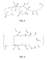
FIG. 2 is a side view schematic diagram of an embodiment of the present disclosure. -
FIG. 3 is a top view schematic diagram of the embodiment ofFIG. 2 . -
FIG. 4 is a front view of a guide roller system which uses spring-loaded pivot mechanisms for mounting cylindrical guide rollers. -
FIG. 5 is a side view of a cylindrical guide roller. -
FIG. 6 is a cross section of the cylindrical guide roller ofFIG. 5 . -
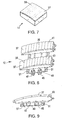
FIG. 7 is a perspective view of a curved air-bar for non-contact support of glass between guide roller pairs. -
FIG. 8 is a perspective view of a curved air-bar assembly having two air-bar subsections which are independently laterally moveable with respect to one another. -
FIG. 9 is a side view of the curved air-bar assembly ofFIG. 8 . -
FIG. 10 is a side view schematic diagram of an embodiment of the present disclosure. -
FIG. 11 is a top view schematic diagram of the embodiment ofFIG. 10 . -
FIG. 12 is a side view schematic diagram of an embodiment of the present disclosure. -
FIG. 13 is a top view schematic diagram of the embodiment ofFIG. 12 . -
FIG. 14 is a side view schematic diagram of an embodiment of the present disclosure. -
FIG. 15 is a side view schematic diagram of an embodiment of the present disclosure. - For ease of presentation, the following discussion is primarily in terms of guiding a thin,
flexible glass ribbon 13 for winding onto acylindrical core 11, it being understood that the guiding apparatus disclosed herein can be used in a variety of other applications, e.g., as part of a process which produces individual glass sheets. - The glass ribbon can be produced by various glass forming processes known in the art, including the overflow downdraw fusion process, the slot draw process, other downdraw processes, the float process, and the like. The ribbon can have various compositions and thicknesses, but in general, the guiding apparatus disclosed herein will be of particular value with thin ribbons having a thickness less than or equal to 0.3 millimeters, e.g., thicknesses on the order of 0.22 millimeters and below. Depending on the processes used, the ribbon can have beaded or non-beaded edges, e.g., the beads can be removed from the ribbon prior to guiding and winding.
-
FIGS. 2-3 show an embodiment of guiding apparatus having a first ribbon-guidingassembly 1 and a second ribbon-guidingassembly 2, where each assembly includes a ribbon-curving subassembly for curvingribbon 13 along its direction ofmotion 15 and a pair of guide rollers (7a,7b for ribbon-guidingassembly edges FIG. 1 ). The apparatus ofFIGS. 2-3 also includes: (a)cylindrical core 11 which rotates counterclockwise inFIG. 2 (see arrow 23) and receivesribbon 13 from the guiding apparatus and forms it into a roll; and (b)free loop 17 which provides mechanical isolation between the guiding apparatus and, for example, the apparatus (not shown) used to form the ribbon. - In the embodiment of
FIGS. 2-3 , different types of ribbon-curving subassemblies are used in ribbon-guidingassemblies cylindrical rollers assembly 1 and a curved air-bar 12 for ribbon-guidingassembly 2. As illustrated inFIGS. 10-11 and12-13 , two curved air-bars cylindrical rollers FIGS. 2-3 but with the air-bar upstream of the rollers. As a further variation, although generally not needed, a ribbon-curving subassembly can employ both a central curved air-bar and an outboard pair of cylindrical rollers. - Whatever ribbon-curving subassemblies are used, their purpose is to create two curved sections in the ribbon without mechanically contacting the
central portion 4 of the ribbon. Thus, when a pair of cylindrical rollers is used, the rollers contact the surface of the ribbon outside of, and on opposite sides of,central portion 4. In this way, the rollers do not damage the central portion which includes the ribbon's quality portion, i.e., the portion of the ribbon which customers use in their products. The rollers also rotate with the ribbon as illustrated byarrows - It should be noted that in
FIG. 1 ,central portion 4 is not to scale (nor is the ribbon or the camber) in that, in practice, the central portion will typically be 90% or more of the ribbon's width, e.g., 95% or more of the width. When an air-bar is used, it can operate on the ribbon's central portion, as well as its edge portions if desired, since the physical structure of the air-bar does not make mechanical contact with the ribbon. The air (or other fluid) used with the air-bar does make physical contact with the surface of the ribbon. However, such physical contact does not constitute "mechanical contact" as that term is used herein since the ribbon is not generally susceptible to substantial mechanical damage by the fluid contact. - However formed, the two curved sections produced by the ribbon-curving subassemblies serve the role of increasing the stiffness of the ribbon so that the guide rollers can move the ribbon laterally without the ribbon buckling. The curvature, however, cannot be too sharp or the ribbon may break. In general terms, the bending stress σ produced in a bent ribbon is given by: σ ≈ 0.5*E*t/R, where E is the glass' Young's modulus, t is its thickness, and R is the radius of curvature of the bend. Thus, the curvature needs to be chosen so that the calculated bending stress does not exceed and, preferably, is substantially below the glass' flexural strength. In practice, for a representative display type glass, it has been found that a 4.5 inch (11.43 cm) radius of curvature will produce an acceptable bending stress (on the order of 50 megapascals) for a 150 micron glass thickness, while at the same time producing a level of stiffness in the ribbon sufficient to allow efficient guiding of the ribbon by the guide rollers. Larger radii of curvature have also been found to work successfully. For example, successful guiding has been achieved for the embodiment of
FIGS. 2 and 3 usingcylindrical rollers bar 12 having a radius of∼36 inches (91.44 cm). The appropriate curvatures for any particular application of the present disclosure can be readily determined by persons skilled in the art from the foregoing. It should be noted that the curvatures produced by the first and second ribbon-curving subassemblies need not be the same. - Surprisingly, it has been found that effective guiding of a thin, flexible, glass ribbon cannot be accomplished with a single curved section produced by a single ribbon-curving subassembly. With only a single curved section, the ribbon can pivot about the guiding rollers, rather than being pointed in a desired direction. With two ribbon-curving subassemblies, on the other hand, the two curved sections of the ribbon produced by the subassemblies can together define a direction for the ribbon, e.g., the direction of the centerline of a tangent plane to the two curved sections. The two pairs of guiding rollers of the two ribbon-guiding assemblies will then keep the ribbon moving in this defined direction.
- To define a direction, the two ribbon-guiding assemblies need to be close enough together so that they do not become mechanically isolated from one another. Otherwise, the pivoting problem can arise again at each ribbon-guiding assembly. Similarly, the two ribbon-guiding assemblies cannot be too close together without becoming overly sensitive to small changes in the system. Generally, the onset of mechanical isolation becomes evident when the ribbon is capable of twisting between the ribbon-guiding assemblies or exhibits substantial amounts of gravitational sag between the assemblies. Supporting the ribbon between the assemblies with a flat air-bar can increase the amount of spacing between the assemblies that can be tolerated without loss of effective guiding. In general terms, for a glass ribbon composed of a display type glass, distances between the curved sections of the ribbon on the order of 0.5 to 2 meters have been found to work successfully in practice, it being expected that longer distances will also work successfully. As with the radii of curvature used for the curved sections of the ribbon, an appropriate spacing between the ribbon-guiding assemblies can be readily determined by persons skilled in the art for any particular application of the present disclosure.
-
FIG. 4 illustrates an embodiment of a guide roller system that can be used as part of the first and second ribbon-guiding assemblies. As shown therein, the system includesframe 20 which carriesguide roller assemblies guide rollers ribbon 13. Each guide roller assembly includes apivot 29 to which is attached apivot arm 6. The pivot arm carries a guide roller and is biased byspring 19 to bring the surface of the roller into contact with the edge of the ribbon. - As can be seen in
FIG. 4 , movement ofribbon 13 to the right increases the lateral force applied to the edge of the ribbon byguide roller 7b and decreases the lateral force applied byguide roller 7a. Accordingly, the ribbon will be moved laterally back towards the centerline between the rollers, i.e., it will be moved back towards the desired direction of travel. Conversely, movement ofribbon 13 to the left will increase/decrease the force applied byguide roller 7a/7b, thus causing the ribbon to again move back towards the centerline between the rollers, in this case by moving laterally to the right. In this way, the guide roller system will cause the ribbon to automatically experience a lateral restoring force appropriate to its deviation from the desired direction of motion for the ribbon. - Because the guide rollers are mounted on spring loaded pivots, the amount of force that is exerted on the edges of the glass ribbon can be easily controlled through the selection of
springs 19. In practice, a lateral force of approximately 0.4-0.5 pounds (0.181 kg to 0.227 kg) has been found to work successfully with a glass ribbons having thicknesses in the range of 0.075 to 0.22 mm and a width of 40 centimeters. Suitable lateral forces for other ribbon dimensions can be readily determined by persons skilled in the art for any particular application of the present disclosure. - As shown in
FIGS. 5 and 6 , the guide roller can include ashaft 31 to which is rotatably mounted aframe 33 which is covered with a resilient coating orsleeve 35. The coating or sleeve can, for example, be composed of a silicone rubber or a similar low-friction complaint material capable of minimizing damage to the edge of the ribbon, e.g., besides silicone rubber, the sleeve can be composed natural rubber, neoprene, or generally any complaint material coated with TEFLON. - Although illustrated for first and
second guide rollers FIGS. 4, 5, and 6 can also be used for third andfourth guide rollers -
FIGS. 7-9 show air-bar assemblies that can be used as part of the first and second ribbon-curving subassemblies. In particular,FIG. 7 shows an air-bar assembly having a one piececurved face 37 penetrated byapertures 39, whileFIGS. 8-9 show an air-bar having first and second air-bar subsections FIGS. 8-9 , the subsections are mounted onrails 51 carried byframe 49 and are independently moveable along the rails through the rotation of first andsecond gear assemblies fluid exiting apertures 39 strikes thecentral portion 4 of the ribbon. Alternatively, the subsections can be mounted so that they operate on the outer portions of the ribbon in a manner similar to that ofcylindrical rollers FIGS. 2-3 and12-13 . The arrangement and size ofapertures 39 and the shape offace 37 follow conventional air-bar technology, with the proviso that the force applied to the ribbon needs to spread across a sufficiently large area so as to avoid localized bulging of the ribbon. Air-bar constructions other than those illustrated can, of course, be used in the practice of the ribbon guiding technology disclosed herein. -
FIGS. 14 and15 show further embodiments for the ribbon guiding system. In theFIG. 14 embodiment, the firstribbon guiding assembly 1 employs a concave air-bar 22 in place of the convex air-bar 14 of the embodiment ofFIGS. 10-11 , and in the embodiment ofFIG. 15 , the ribbon's overall motion includes primarily a vertical component, rather than primarily a horizontal component as in the embodiments ofFIGS. 2-3 ,10-11 ,12-13, and 14 . Tobias ribbon 13 against the first and second ribbon-curvingsubassemblies FIG. 15 , theFIG. 15 embodiment includes ribbon-biasingassembly 18 which can, for example, be a curved air-bar or a pair of cylindrical rollers. As can be seen inFIG. 15 , the ribbon-biasingassembly 18 produces a further curved section in the ribbon between the curved sections produced by ribbon-curvingsubassemblies - As discussed above, one application for the ribbon guiding systems disclosed herein is in connection with the winding of a glass ribbon. In accordance with an embodiment of such winding,
ribbon 13 is manufactured continuously and once the manufacturing process is stable, the ribbon is formed into afree loop 17 and then for the embodiment ofFIGS. 2-3 , threaded over the top of a set of narrowcylindrical rollers guide rollers bar 12. A second set ofguide rollers cylindrical core 11. The process continues until the cylindrical core is full. A cross cut device (not shown) then creates a trailing edge. The operator wraps and tapes this trailing edge to the newly-formed glass roll and removes the finished roll. The operator then loads a new core and the process is repeated. Similar steps can be used with the equipment of the embodiments ofFIGS. 10-11 ,12-13 ,14 , and15 . - In practice, the foregoing winding procedure has been successfully used to wind glass lengths of greater than 200m on a cylindrical core. The camber of the glass ribbon being wound was measured to be approximately 3mm over a 5.5m length and the cross-web thickness variation was measured to be 0.013mm for 0.15mm thick material.
- From the foregoing, it can be seen that apparatus and methods for guiding a thin, flexible, glass ribbon have been provided which create sufficient forces to effectively guide the glass web laterally, despite the potential existence of camber or thickness variation in the glass. In some embodiments (see, for example,
FIGS. 10-11 ,14 , and15 ), these forces can be produced without any mechanical contact with the major surfaces of the glass ribbon. Moreover, the total force applied to the edge of the glass can be limited (e.g., through the pivot system ofFIG. 4 ) so as to minimize the creation of defects that could lead to breakage. Similarly, by coating the guide rollers with a complaint, low friction material, the edges of the glass can be further protected from the generation of defects that could result in breakage. - A variety of modifications that do not depart from the scope and spirit of the invention will be evident to persons of ordinary skill in the art from the foregoing disclosure. The following claims are intended to cover the specific embodiments set forth herein as well as modifications, variations, and equivalents of those embodiments.
Claims (15)
- Apparatus for guiding a moving glass ribbon having a central portion and first and second edges comprising:(a) a first ribbon-guiding assembly comprising:(i) a first ribbon-curving subassembly for producing a first curved section of the ribbon without mechanically contacting the central portion of the ribbon, the curvature of the section being along the direction of motion of the ribbon; and(ii) first and second guide rollers for engaging and applying lateral force to, respectively, the first and second edges of the ribbon, the engagement being in or mechanically adjacent the first curved section of the ribbon; and(b) a second ribbon-guiding assembly comprising:(i) a second ribbon-curving subassembly for producing a second curved section of the ribbon without mechanically contacting the central portion of the ribbon, the curvature of the section being along the direction of motion of the ribbon; and(ii) third and fourth guide rollers for engaging and applying lateral force to, respectively, the first and second edges of the ribbon, the engagement being in or mechanically adjacent the second curved section of the ribbon;
wherein the curvatures of each of the first and second sections stiffens the ribbon to an extent sufficient to permit the guide rollers to laterally move the ribbon without causing it to buckle. - The apparatus of Claim 1 wherein:(a) the first ribbon-curving subassembly comprises at least one of:(i) a curved air-bar, and(ii) a pair of cylindrical rollers which contact the surface of the ribbon outside of, and on opposite sides of, the ribbon's central portion; and(b) the second ribbon-curving subassembly comprises at least one of:(i) a curved air-bar, and(ii) a pair of cylindrical rollers which contact the surface of the ribbon outside of, and on opposite sides of, the ribbon's central portion.
- The apparatus of Claim 1 or Claim 2 wherein each of the guide rollers is carried by a pivot arm and each of the pivot arms is spring-loaded to bias its guide roller against the edge of the ribbon.
- The apparatus of any one of Claims 1-3 wherein the apparatus comprises a ribbon-biasing assembly between the first and second ribbon-guiding assemblies for biasing the ribbon towards the first and second ribbon-curving subassemblies without mechanically contacting the central portion of the ribbon.
- The apparatus of Claim 4 wherein the ribbon-biasing assembly comprises at least one of:(a) a curved air-bar, and(b) a pair of cylindrical rollers which contact the surface of the ribbon outside of, and on opposite sides of, the ribbon's central portion.
- The apparatus of any one of Claims 1-5 wherein at least one of the first and second ribbon-curving subassemblies comprises a curved air-bar having first and second curved air-bar subsections whose across-the-ribbon positions are independently adjustable.
- The apparatus of any one of Claims 1-6 wherein the ribbon's central portion is at least 90% of the ribbon's width.
- A method for guiding a moving glass ribbon having a central portion and first and second edges comprising:(a) creating a first curved section of the ribbon without mechanically contacting the central portion of the ribbon, the curvature of the section being along the direction of motion of the ribbon;(b) applying lateral forces to the first and second edges of the ribbon in or mechanically adjacent to the first curved section of the ribbon;(c) creating a second curved section of the ribbon without mechanically contacting the central portion of the ribbon, the curvature of the section being along the direction of motion of the ribbon; and(d) applying lateral forces to the first and second edges of the ribbon in or mechanically adjacent to the second curved section of the ribbon;
wherein the curvatures of each of the first and second sections stiffens the ribbon to an extent sufficient to permit the lateral forces to guide the ribbon without causing it to buckle. - The method of Claim 8 wherein the curvatures of the first and second sections of the ribbon are concave towards the same side of the ribbon.
- The method of Claim 9 wherein the ribbon is guided while its motion includes primarily a vertical component and the method further comprises creating a third curved section of the ribbon between the first and second curved sections without mechanically contacting the central portion of the ribbon, the curvature of the third section being: (i) along the direction of motion of the ribbon and (ii) concave in a direction opposite to that of the first and second curved sections.
- The method of Claims 8 or Claim 9 wherein the ribbon is guided while its motion includes primarily a horizontal component and the curvatures are concave downward.
- The method of Claim 8 wherein the curvatures of the first and second sections of the ribbon are concave towards opposite sides of the ribbon.
- The method of any one of Claims 8-12 wherein the first and second curved sections are each produced by at least one of:(a) a curved air-bar, and(b) a pair of cylindrical rollers which contact the surface of the ribbon outside of, and on opposite sides of, the ribbon's central portion.
- The method of any one of Claims 8-13 further comprising using a pair of curved air-bars to produce at least one of the first and second curved sections of the ribbon and adjusting an across-the-ribbon position of at least one of the pair of curved air-bars at least once.
- The method of any one of Claim 8-14 wherein the ribbon has a thickness which is less than or equal to 0.3 millimeters.
Applications Claiming Priority (1)
| Application Number | Priority Date | Filing Date | Title |
|---|---|---|---|
| US41007510P | 2010-11-04 | 2010-11-04 |
Publications (3)
| Publication Number | Publication Date |
|---|---|
| EP2450301A2 true EP2450301A2 (en) | 2012-05-09 |
| EP2450301A3 EP2450301A3 (en) | 2012-12-05 |
| EP2450301B1 EP2450301B1 (en) | 2014-03-05 |
Family
ID=45001648
Family Applications (1)
| Application Number | Title | Priority Date | Filing Date |
|---|---|---|---|
| EP11187395.6A Not-in-force EP2450301B1 (en) | 2010-11-04 | 2011-11-01 | Methods and apparatus for guiding flexible glass ribbons |
Country Status (6)
| Country | Link |
|---|---|
| US (1) | US9199816B2 (en) |
| EP (1) | EP2450301B1 (en) |
| JP (1) | JP5881374B2 (en) |
| KR (1) | KR101699556B1 (en) |
| CN (2) | CN102583992B (en) |
| TW (1) | TWI537224B (en) |
Cited By (1)
| Publication number | Priority date | Publication date | Assignee | Title |
|---|---|---|---|---|
| CN115279676A (en) * | 2020-03-19 | 2022-11-01 | 日本电气硝子株式会社 | Method for manufacturing glass roll and device for manufacturing glass roll |
Families Citing this family (29)
| Publication number | Priority date | Publication date | Assignee | Title |
|---|---|---|---|---|
| US9199816B2 (en) * | 2010-11-04 | 2015-12-01 | Corning Incorporated | Methods and apparatus for guiding flexible glass ribbons |
| US9428359B2 (en) * | 2011-11-30 | 2016-08-30 | Corning Incorporated | Methods and apparatuses for conveying flexible glass substrates |
| WO2013181060A1 (en) * | 2012-05-30 | 2013-12-05 | Corning Incorporated | Apparatus and method for inspecting a flexible glass ribbon |
| US9038414B2 (en) * | 2012-09-26 | 2015-05-26 | Corning Incorporated | Methods and apparatuses for steering flexible glass webs |
| TW201420464A (en) | 2012-11-26 | 2014-06-01 | Ind Tech Res Inst | Transporting apparatus |
| WO2014179422A1 (en) | 2013-05-03 | 2014-11-06 | Corning Incorporated | Methods and apparatus for conveying a glass ribbon |
| WO2015029669A1 (en) * | 2013-08-28 | 2015-03-05 | 日本電気硝子株式会社 | Method for conveying thin sheet glass, conveyance device, cutting method, and method for producing glass article |
| JP6056711B2 (en) * | 2013-08-28 | 2017-01-11 | 日本電気硝子株式会社 | Thin glass cutting method and glass article manufacturing method |
| JP6056710B2 (en) * | 2013-08-28 | 2017-01-11 | 日本電気硝子株式会社 | Thin glass conveying method and conveying device |
| US20150239700A1 (en) * | 2014-02-26 | 2015-08-27 | David James Cornell | Air shoe with integrated roller |
| DE102014103431B4 (en) | 2014-03-13 | 2015-10-01 | Schott Ag | Method and apparatus for reducing the saberiness of thin glasses and thereafter produced thin glass band |
| US20150344347A1 (en) * | 2014-05-29 | 2015-12-03 | Corning Incorporated | Apparatuses for steering flexible glass webs and methods for using the same |
| US20150345996A1 (en) * | 2014-05-29 | 2015-12-03 | Corning Incorporated | Apparatuses and methods for measuring an angle between a web of material and a conveyance direction |
| US10570047B2 (en) * | 2014-07-08 | 2020-02-25 | Corning Incorporated | Continuous processing of flexible glass ribbon |
| KR102474099B1 (en) | 2015-05-18 | 2022-12-05 | 코닝 인코포레이티드 | Methods and systems for processing glass ribbons |
| DE102015108553B4 (en) | 2015-05-29 | 2019-02-14 | Schott Ag | Methods and devices for reducing the saberiness of thin glasses |
| WO2017161104A1 (en) * | 2016-03-17 | 2017-09-21 | Corning Incorporated | Methods and apparatus for supporting glass |
| CN107523551A (en) * | 2016-06-20 | 2017-12-29 | 中国农业科学院饲料研究所 | A kind of anti-Bacillus coli cells strain and recombinant single chain antibody and preparation method thereof |
| JP6720900B2 (en) * | 2017-03-14 | 2020-07-08 | 日本電気硝子株式会社 | Glass roll manufacturing method |
| US20200189870A1 (en) * | 2017-04-28 | 2020-06-18 | 3M Innovative Properties Company | Passive edge guiding method and apparatus |
| JP7106627B2 (en) | 2017-07-11 | 2022-07-26 | コーニング インコーポレイテッド | Apparatus and method for processing glass |
| US20240025791A1 (en) * | 2017-10-30 | 2024-01-25 | Corning Incorporated | Systems and methods for processing thin glass ribbons |
| EP3704046B1 (en) * | 2017-10-30 | 2023-02-15 | Corning Incorporated | Systems and methods for processing thin glass ribbons |
| WO2019089527A1 (en) * | 2017-10-31 | 2019-05-09 | Corning Incorporated | Systems and methods for processing thin glass ribbons |
| CN107935368B (en) * | 2017-12-26 | 2023-10-17 | 中建材玻璃新材料研究院集团有限公司 | A scratch-free transport roller for ultra-thin flat glass |
| CN113631524B (en) | 2018-12-13 | 2023-04-11 | 康宁公司 | Conveying apparatus and conveying belt |
| JP7404815B2 (en) * | 2019-11-27 | 2023-12-26 | 日本電気硝子株式会社 | Glass roll manufacturing method |
| KR20220010365A (en) * | 2020-07-17 | 2022-01-25 | 코닝 인코포레이티드 | a system and a method for forming glass rolls |
| CN116583486B (en) | 2020-11-24 | 2026-01-16 | 康宁股份有限公司 | Method and apparatus for manufacturing glass ribbon |
Family Cites Families (72)
| Publication number | Priority date | Publication date | Assignee | Title |
|---|---|---|---|---|
| US769850A (en) | 1904-04-23 | 1904-09-13 | Gustavus S Thompson | Automatic belt-guide. |
| US1399547A (en) * | 1919-08-01 | 1921-12-06 | Robert G Ewing | Sheet-glass-drawing apparatus |
| US2262638A (en) | 1941-01-30 | 1941-11-11 | Crucible Steel Co America | Strip guiding apparatus |
| US3089801A (en) | 1957-05-27 | 1963-05-14 | Minnesota Mining & Mfg | Ultra-thin glass sheet |
| US3574030A (en) | 1962-04-10 | 1971-04-06 | Corning Glass Works | Method of making flexible glass laminates |
| FR96106E (en) * | 1964-04-11 | 1972-05-19 | Libbey Owens Ford Co | Flat glass handling process. |
| US3391053A (en) | 1964-10-29 | 1968-07-02 | Corning Glass Works | Flexible glass-plastic laminate |
| US3485615A (en) * | 1967-03-24 | 1969-12-23 | Libbey Owens Ford Glass Co | Glass sheet supporting and conveying apparatus with means to change the contour of the conveyor |
| US3565596A (en) | 1967-08-30 | 1971-02-23 | Libbey Owens Ford Co | Apparatus for creating a gas film over a curved surface supporting a glass ribbon |
| US3573026A (en) | 1968-02-26 | 1971-03-30 | Libbey Owens Ford Co | Apparatus for deflecting softened glass sheet material from one direction to another direction of draw |
| US3593841A (en) | 1969-11-03 | 1971-07-20 | United States Steel Corp | Idler roller actuating device |
| LU60747A1 (en) * | 1970-04-17 | 1972-03-03 | ||
| US3771987A (en) * | 1971-04-05 | 1973-11-13 | Libbey Owens Ford Co | Apparatus for conveying a glass ribbon |
| GB1370945A (en) * | 1971-04-16 | 1974-10-16 | Triplex Safety Glass Co | Conveying apparatus |
| US3701644A (en) * | 1971-11-03 | 1972-10-31 | Ppg Industries Inc | Method and apparatus for shaping glass sheets with opposed roller sets |
| FR2189330B1 (en) * | 1972-06-23 | 1974-10-25 | Saint Gobain Pont A Mousson | |
| US3913729A (en) | 1972-08-11 | 1975-10-21 | Cambridge Wire Cloth | Belt aligner |
| CA1001842A (en) * | 1972-10-02 | 1976-12-21 | Domtar Limited | Air bearing moisture profiler |
| US3877919A (en) * | 1973-09-26 | 1975-04-15 | Ppg Industries Inc | Traction Rolls for Use in Glass Making |
| CH623793A5 (en) | 1977-10-14 | 1981-06-30 | Gretag Ag | |
| US4182472A (en) * | 1978-07-13 | 1980-01-08 | W. R. Grace & Co. | Contactless turning guide for running webs |
| US4226608A (en) * | 1979-05-14 | 1980-10-07 | Shatterproof Glass Corporation | Method and apparatus for curving glass sheets |
| DE3067590D1 (en) | 1980-01-02 | 1984-05-24 | Agfa Gevaert Nv | Web controlling apparatus |
| US4367031A (en) | 1980-07-11 | 1983-01-04 | Xerox Corporation | Edge guide for belt tracking |
| US4608073A (en) * | 1983-09-12 | 1986-08-26 | Casso Solar Corporation | Roller conveyor for a glass furnace |
| US4556406A (en) * | 1984-10-25 | 1985-12-03 | Ppg Industries, Inc. | Compound bend roll forming |
| US4612030A (en) * | 1985-06-11 | 1986-09-16 | Smids Ronald E | Method and apparatus for making variegated, cathedral, antique or flashed glass in a continuous sheet |
| US4626267A (en) * | 1985-09-16 | 1986-12-02 | Ppg Industries, Inc. | Method and apparatus to reduce tip curl of a glass sheet on a bending mold |
| US6014873A (en) * | 1990-09-26 | 2000-01-18 | Asahi Glass Company Ltd. | Process for bend-shaping a glass plate and an apparatus for bend-shaping the glass plate |
| FR2691454B1 (en) * | 1992-05-21 | 1994-07-08 | Saint Gobain Vitrage Int | METHOD AND DEVICE FOR OBTAINING BOMBED GLASS SHEETS. |
| US5383006A (en) | 1993-12-02 | 1995-01-17 | Xerox Corporation | Compliant edge guide belt loops |
| US5558263A (en) * | 1994-07-26 | 1996-09-24 | Eastman Kodak Company | Apparatus and method for non-contact active tensioning and steering of moving webs |
| EP0716339B1 (en) | 1994-12-05 | 2001-09-12 | Agfa-Gevaert N.V. | A silver halide photographic material and a dry imaging material comprising a glass support |
| US5762674A (en) | 1995-09-27 | 1998-06-09 | Glasstech, Inc. | Apparatus for coating glass sheet ribbon |
| SE507733C2 (en) | 1996-11-01 | 1998-07-06 | Svedala Trellex Ab | Conveyor Control |
| DE19649488A1 (en) | 1996-11-29 | 1997-11-06 | Schott Glaswerke | Pneumatic handling or transport system and for thin glass sheet in display manufacture |
| TW546261B (en) * | 1997-11-06 | 2003-08-11 | Nippon Sheet Glass Co Ltd | Method and apparatus for producing bent glass sheet |
| US6004432A (en) * | 1998-01-28 | 1999-12-21 | Beloit Technologies, Inc. | Sheet turn with vectored air supply |
| US6125754A (en) | 1998-10-30 | 2000-10-03 | Harris; J. C. | Web pressurizing channeled roller and method |
| JP4373612B2 (en) * | 1998-12-03 | 2009-11-25 | 日本板硝子株式会社 | Method and apparatus for manufacturing bent glass sheet |
| US6363753B1 (en) * | 1998-12-03 | 2002-04-02 | Nippon Sheet Glass Co., Ltd. | Curved glass manufacturing apparatus with improved bending and conveyor units |
| JP2000290029A (en) * | 1999-04-01 | 2000-10-17 | Nippon Sheet Glass Co Ltd | Belt for forming glass sheet and production of bent glass sheet using the belt |
| DE19918936A1 (en) * | 1999-04-27 | 2000-11-02 | Schott Glas | Method and device for producing single glass panes |
| DE10045479A1 (en) | 2000-09-14 | 2002-04-04 | Schott Glas | Method and device for contactless storage and transportation of flat glass |
| DE10112415A1 (en) * | 2001-03-15 | 2002-10-02 | Koenig & Bauer Ag | turning bar |
| DE10115259C1 (en) | 2001-03-28 | 2002-10-02 | Kiefel Extrusion Gmbh | Air turning bar |
| DE10156961B4 (en) * | 2001-11-20 | 2005-12-01 | Schott Ag | Device for supporting a glass ribbon |
| JP2005520774A (en) | 2002-03-22 | 2005-07-14 | コーニング インコーポレイテッド | Tow roll used in the production of flat glass |
| JP4178443B2 (en) | 2002-06-24 | 2008-11-12 | 旭硝子株式会社 | Sheet glass manufacturing method and apparatus |
| JP4218263B2 (en) * | 2002-06-24 | 2009-02-04 | 旭硝子株式会社 | Sheet glass manufacturing method |
| US20060042314A1 (en) * | 2004-08-27 | 2006-03-02 | Abbott John S Iii | Noncontact glass sheet stabilization device used in fusion forming of a glass sheet |
| JP2006264970A (en) * | 2005-03-25 | 2006-10-05 | Fuji Photo Film Co Ltd | Web processing system |
| EP1710212A1 (en) * | 2005-04-06 | 2006-10-11 | Corning Incorporated | process and device for manufacturing flat sheets of a glass-based material |
| EP1721872A1 (en) * | 2005-05-10 | 2006-11-15 | Corning Incorporated | Method of producing a glass sheet |
| KR101213991B1 (en) | 2005-12-16 | 2012-12-20 | 엘아이지에이디피 주식회사 | Substrate conveyer and substrate conveying method |
| JP4779706B2 (en) * | 2006-02-28 | 2011-09-28 | Jfeスチール株式会社 | Steel strip winding device and steel strip winding method |
| WO2007132797A1 (en) * | 2006-05-16 | 2007-11-22 | National Institute Of Advanced Industrial Science And Technology | Method and apparatus for manufacturing plate glass by roll forming, and plate glass product |
| CN101454250B (en) * | 2006-05-25 | 2012-10-24 | 麻省理工学院 | Method for shaping sheet thermoplastic and the like |
| EP2204355A4 (en) | 2007-10-30 | 2012-10-31 | Asahi Glass Co Ltd | METHOD FOR PRODUCING A GLASS / RESIN COMPOSITE |
| JP5228445B2 (en) * | 2007-11-01 | 2013-07-03 | セントラル硝子株式会社 | Glass ribbon transfer assist device |
| JP5788134B2 (en) | 2008-10-01 | 2015-09-30 | 日本電気硝子株式会社 | GLASS ROLL AND GLASS ROLL MANUFACTURING METHOD |
| JP5532507B2 (en) | 2008-10-01 | 2014-06-25 | 日本電気硝子株式会社 | Glass roll and glass roll processing method |
| JP5532506B2 (en) | 2008-10-01 | 2014-06-25 | 日本電気硝子株式会社 | Glass roll |
| JP5435267B2 (en) | 2008-10-01 | 2014-03-05 | 日本電気硝子株式会社 | Glass roll, glass roll manufacturing apparatus, and glass roll manufacturing method |
| JP5691148B2 (en) | 2008-10-01 | 2015-04-01 | 日本電気硝子株式会社 | Glass roll, glass roll manufacturing apparatus, and glass roll manufacturing method |
| US8656738B2 (en) * | 2008-10-31 | 2014-02-25 | Corning Incorporated | Glass sheet separating device |
| US8899078B2 (en) * | 2008-11-26 | 2014-12-02 | Corning Incorporated | Glass sheet stabilizing system, glass manufacturing system and method for making a glass sheet |
| ATE551304T1 (en) * | 2009-05-13 | 2012-04-15 | Corning Inc | METHOD AND EQUIPMENT FOR SHAPING ENDLESS GLASS PANELS |
| JP5645063B2 (en) * | 2010-07-23 | 2014-12-24 | 日本電気硝子株式会社 | Glass film manufacturing apparatus and manufacturing method |
| US9199816B2 (en) | 2010-11-04 | 2015-12-01 | Corning Incorporated | Methods and apparatus for guiding flexible glass ribbons |
| US9790121B2 (en) * | 2011-03-30 | 2017-10-17 | Corning Incorporated | Methods of fabricating a glass ribbon |
| US20120255672A1 (en) * | 2011-04-11 | 2012-10-11 | Marshall Dale C | Methods and apparatuses for applying a handling tab to continuous glass ribbons |
-
2011
- 2011-10-13 US US13/272,511 patent/US9199816B2/en not_active Expired - Fee Related
- 2011-11-01 EP EP11187395.6A patent/EP2450301B1/en not_active Not-in-force
- 2011-11-02 JP JP2011240910A patent/JP5881374B2/en not_active Expired - Fee Related
- 2011-11-03 TW TW100140156A patent/TWI537224B/en not_active IP Right Cessation
- 2011-11-04 CN CN201110364431.2A patent/CN102583992B/en not_active Expired - Fee Related
- 2011-11-04 KR KR1020110114595A patent/KR101699556B1/en not_active Expired - Fee Related
- 2011-11-04 CN CN2011204426560U patent/CN202359018U/en not_active Expired - Fee Related
Cited By (1)
| Publication number | Priority date | Publication date | Assignee | Title |
|---|---|---|---|---|
| CN115279676A (en) * | 2020-03-19 | 2022-11-01 | 日本电气硝子株式会社 | Method for manufacturing glass roll and device for manufacturing glass roll |
Also Published As
| Publication number | Publication date |
|---|---|
| EP2450301A3 (en) | 2012-12-05 |
| CN102583992B (en) | 2015-03-11 |
| KR20120047836A (en) | 2012-05-14 |
| US9199816B2 (en) | 2015-12-01 |
| TWI537224B (en) | 2016-06-11 |
| TW201226298A (en) | 2012-07-01 |
| CN202359018U (en) | 2012-08-01 |
| JP5881374B2 (en) | 2016-03-09 |
| CN102583992A (en) | 2012-07-18 |
| US20120111054A1 (en) | 2012-05-10 |
| EP2450301B1 (en) | 2014-03-05 |
| KR101699556B1 (en) | 2017-01-24 |
| JP2012096989A (en) | 2012-05-24 |
Similar Documents
| Publication | Publication Date | Title |
|---|---|---|
| EP2450301B1 (en) | Methods and apparatus for guiding flexible glass ribbons | |
| CN104520218B (en) | For the method and apparatus transmitting flexible glass substrate | |
| CN105189378B (en) | Ways to Handle Glass Ribbon | |
| EP3166896B1 (en) | Continuous processing of flexible glass ribbon | |
| EP2697056B1 (en) | Methods and apparatuses for applying a handling tab to continuous glass ribbons | |
| KR102475283B1 (en) | Continuous Processing of Flexible Glass Ribbons with Ribbon Isolation and Stabilization | |
| CN104919104B (en) | Method and apparatus for manipulating flexible glass webs | |
| EP3297964B1 (en) | Continuous processing of flexible glass ribbon with reduced mechanical stress | |
| TWI487676B (en) | Glass plate manufacturing method | |
| US20190010072A1 (en) | Method and apparatus for continuous processing of a flexible glass ribbon | |
| EP3704046B1 (en) | Systems and methods for processing thin glass ribbons | |
| WO2011132602A1 (en) | Glass plate conveyance method, glass plate conveyance device, and production method for glass plate products | |
| CN115279676A (en) | Method for manufacturing glass roll and device for manufacturing glass roll | |
| CN103608718A (en) | Knife edge and liquid-crystal display device manufacturing system including same | |
| US3779138A (en) | Curl corrector apparatus for operating on a continuous web | |
| CN111634737A (en) | A two-way rectifying device | |
| CN117480130B (en) | Method and apparatus for manufacturing glass ribbons | |
| CN116583486B (en) | Method and apparatus for manufacturing glass ribbon | |
| CN117985538A (en) | Optical fiber winding tension adjusting structure and winding device |
Legal Events
| Date | Code | Title | Description |
|---|---|---|---|
| PUAI | Public reference made under article 153(3) epc to a published international application that has entered the european phase |
Free format text: ORIGINAL CODE: 0009012 |
|
| AK | Designated contracting states |
Kind code of ref document: A2 Designated state(s): AL AT BE BG CH CY CZ DE DK EE ES FI FR GB GR HR HU IE IS IT LI LT LU LV MC MK MT NL NO PL PT RO RS SE SI SK SM TR |
|
| AX | Request for extension of the european patent |
Extension state: BA ME |
|
| REG | Reference to a national code |
Ref country code: DE Ref legal event code: R079 Ref document number: 602011005216 Country of ref document: DE Free format text: PREVIOUS MAIN CLASS: B65H0023020000 Ipc: B65H0023032000 |
|
| PUAL | Search report despatched |
Free format text: ORIGINAL CODE: 0009013 |
|
| RIC1 | Information provided on ipc code assigned before grant |
Ipc: B65H 23/032 20060101AFI20121019BHEP Ipc: C03B 35/24 20060101ALI20121019BHEP |
|
| AK | Designated contracting states |
Kind code of ref document: A3 Designated state(s): AL AT BE BG CH CY CZ DE DK EE ES FI FR GB GR HR HU IE IS IT LI LT LU LV MC MK MT NL NO PL PT RO RS SE SI SK SM TR |
|
| AX | Request for extension of the european patent |
Extension state: BA ME |
|
| 17P | Request for examination filed |
Effective date: 20121107 |
|
| GRAP | Despatch of communication of intention to grant a patent |
Free format text: ORIGINAL CODE: EPIDOSNIGR1 |
|
| INTG | Intention to grant announced |
Effective date: 20140107 |
|
| GRAS | Grant fee paid |
Free format text: ORIGINAL CODE: EPIDOSNIGR3 |
|
| GRAA | (expected) grant |
Free format text: ORIGINAL CODE: 0009210 |
|
| AK | Designated contracting states |
Kind code of ref document: B1 Designated state(s): AL AT BE BG CH CY CZ DE DK EE ES FI FR GB GR HR HU IE IS IT LI LT LU LV MC MK MT NL NO PL PT RO RS SE SI SK SM TR |
|
| REG | Reference to a national code |
Ref country code: GB Ref legal event code: FG4D |
|
| REG | Reference to a national code |
Ref country code: CH Ref legal event code: EP |
|
| REG | Reference to a national code |
Ref country code: AT Ref legal event code: REF Ref document number: 654719 Country of ref document: AT Kind code of ref document: T Effective date: 20140315 |
|
| REG | Reference to a national code |
Ref country code: IE Ref legal event code: FG4D |
|
| REG | Reference to a national code |
Ref country code: DE Ref legal event code: R096 Ref document number: 602011005216 Country of ref document: DE Effective date: 20140417 |
|
| REG | Reference to a national code |
Ref country code: AT Ref legal event code: MK05 Ref document number: 654719 Country of ref document: AT Kind code of ref document: T Effective date: 20140305 |
|
| REG | Reference to a national code |
Ref country code: NL Ref legal event code: VDEP Effective date: 20140305 |
|
| PG25 | Lapsed in a contracting state [announced via postgrant information from national office to epo] |
Ref country code: LT Free format text: LAPSE BECAUSE OF FAILURE TO SUBMIT A TRANSLATION OF THE DESCRIPTION OR TO PAY THE FEE WITHIN THE PRESCRIBED TIME-LIMIT Effective date: 20140305 Ref country code: NO Free format text: LAPSE BECAUSE OF FAILURE TO SUBMIT A TRANSLATION OF THE DESCRIPTION OR TO PAY THE FEE WITHIN THE PRESCRIBED TIME-LIMIT Effective date: 20140605 |
|
| REG | Reference to a national code |
Ref country code: LT Ref legal event code: MG4D |
|
| PG25 | Lapsed in a contracting state [announced via postgrant information from national office to epo] |
Ref country code: SE Free format text: LAPSE BECAUSE OF FAILURE TO SUBMIT A TRANSLATION OF THE DESCRIPTION OR TO PAY THE FEE WITHIN THE PRESCRIBED TIME-LIMIT Effective date: 20140305 Ref country code: CY Free format text: LAPSE BECAUSE OF FAILURE TO SUBMIT A TRANSLATION OF THE DESCRIPTION OR TO PAY THE FEE WITHIN THE PRESCRIBED TIME-LIMIT Effective date: 20140305 Ref country code: AT Free format text: LAPSE BECAUSE OF FAILURE TO SUBMIT A TRANSLATION OF THE DESCRIPTION OR TO PAY THE FEE WITHIN THE PRESCRIBED TIME-LIMIT Effective date: 20140305 Ref country code: FI Free format text: LAPSE BECAUSE OF FAILURE TO SUBMIT A TRANSLATION OF THE DESCRIPTION OR TO PAY THE FEE WITHIN THE PRESCRIBED TIME-LIMIT Effective date: 20140305 |
|
| PG25 | Lapsed in a contracting state [announced via postgrant information from national office to epo] |
Ref country code: RS Free format text: LAPSE BECAUSE OF FAILURE TO SUBMIT A TRANSLATION OF THE DESCRIPTION OR TO PAY THE FEE WITHIN THE PRESCRIBED TIME-LIMIT Effective date: 20140305 Ref country code: LV Free format text: LAPSE BECAUSE OF FAILURE TO SUBMIT A TRANSLATION OF THE DESCRIPTION OR TO PAY THE FEE WITHIN THE PRESCRIBED TIME-LIMIT Effective date: 20140305 Ref country code: HR Free format text: LAPSE BECAUSE OF FAILURE TO SUBMIT A TRANSLATION OF THE DESCRIPTION OR TO PAY THE FEE WITHIN THE PRESCRIBED TIME-LIMIT Effective date: 20140305 |
|
| PG25 | Lapsed in a contracting state [announced via postgrant information from national office to epo] |
Ref country code: RO Free format text: LAPSE BECAUSE OF FAILURE TO SUBMIT A TRANSLATION OF THE DESCRIPTION OR TO PAY THE FEE WITHIN THE PRESCRIBED TIME-LIMIT Effective date: 20140305 Ref country code: IS Free format text: LAPSE BECAUSE OF FAILURE TO SUBMIT A TRANSLATION OF THE DESCRIPTION OR TO PAY THE FEE WITHIN THE PRESCRIBED TIME-LIMIT Effective date: 20140705 Ref country code: BE Free format text: LAPSE BECAUSE OF FAILURE TO SUBMIT A TRANSLATION OF THE DESCRIPTION OR TO PAY THE FEE WITHIN THE PRESCRIBED TIME-LIMIT Effective date: 20140305 Ref country code: NL Free format text: LAPSE BECAUSE OF FAILURE TO SUBMIT A TRANSLATION OF THE DESCRIPTION OR TO PAY THE FEE WITHIN THE PRESCRIBED TIME-LIMIT Effective date: 20140305 Ref country code: BG Free format text: LAPSE BECAUSE OF FAILURE TO SUBMIT A TRANSLATION OF THE DESCRIPTION OR TO PAY THE FEE WITHIN THE PRESCRIBED TIME-LIMIT Effective date: 20140605 Ref country code: EE Free format text: LAPSE BECAUSE OF FAILURE TO SUBMIT A TRANSLATION OF THE DESCRIPTION OR TO PAY THE FEE WITHIN THE PRESCRIBED TIME-LIMIT Effective date: 20140305 Ref country code: CZ Free format text: LAPSE BECAUSE OF FAILURE TO SUBMIT A TRANSLATION OF THE DESCRIPTION OR TO PAY THE FEE WITHIN THE PRESCRIBED TIME-LIMIT Effective date: 20140305 |
|
| PG25 | Lapsed in a contracting state [announced via postgrant information from national office to epo] |
Ref country code: SK Free format text: LAPSE BECAUSE OF FAILURE TO SUBMIT A TRANSLATION OF THE DESCRIPTION OR TO PAY THE FEE WITHIN THE PRESCRIBED TIME-LIMIT Effective date: 20140305 Ref country code: PL Free format text: LAPSE BECAUSE OF FAILURE TO SUBMIT A TRANSLATION OF THE DESCRIPTION OR TO PAY THE FEE WITHIN THE PRESCRIBED TIME-LIMIT Effective date: 20140305 Ref country code: ES Free format text: LAPSE BECAUSE OF FAILURE TO SUBMIT A TRANSLATION OF THE DESCRIPTION OR TO PAY THE FEE WITHIN THE PRESCRIBED TIME-LIMIT Effective date: 20140305 |
|
| REG | Reference to a national code |
Ref country code: DE Ref legal event code: R097 Ref document number: 602011005216 Country of ref document: DE |
|
| PG25 | Lapsed in a contracting state [announced via postgrant information from national office to epo] |
Ref country code: PT Free format text: LAPSE BECAUSE OF FAILURE TO SUBMIT A TRANSLATION OF THE DESCRIPTION OR TO PAY THE FEE WITHIN THE PRESCRIBED TIME-LIMIT Effective date: 20140707 |
|
| PLBE | No opposition filed within time limit |
Free format text: ORIGINAL CODE: 0009261 |
|
| STAA | Information on the status of an ep patent application or granted ep patent |
Free format text: STATUS: NO OPPOSITION FILED WITHIN TIME LIMIT |
|
| PG25 | Lapsed in a contracting state [announced via postgrant information from national office to epo] |
Ref country code: DK Free format text: LAPSE BECAUSE OF FAILURE TO SUBMIT A TRANSLATION OF THE DESCRIPTION OR TO PAY THE FEE WITHIN THE PRESCRIBED TIME-LIMIT Effective date: 20140305 |
|
| 26N | No opposition filed |
Effective date: 20141208 |
|
| REG | Reference to a national code |
Ref country code: DE Ref legal event code: R097 Ref document number: 602011005216 Country of ref document: DE Effective date: 20141208 |
|
| PG25 | Lapsed in a contracting state [announced via postgrant information from national office to epo] |
Ref country code: IT Free format text: LAPSE BECAUSE OF FAILURE TO SUBMIT A TRANSLATION OF THE DESCRIPTION OR TO PAY THE FEE WITHIN THE PRESCRIBED TIME-LIMIT Effective date: 20140305 |
|
| PG25 | Lapsed in a contracting state [announced via postgrant information from national office to epo] |
Ref country code: SI Free format text: LAPSE BECAUSE OF FAILURE TO SUBMIT A TRANSLATION OF THE DESCRIPTION OR TO PAY THE FEE WITHIN THE PRESCRIBED TIME-LIMIT Effective date: 20140305 |
|
| PG25 | Lapsed in a contracting state [announced via postgrant information from national office to epo] |
Ref country code: MC Free format text: LAPSE BECAUSE OF FAILURE TO SUBMIT A TRANSLATION OF THE DESCRIPTION OR TO PAY THE FEE WITHIN THE PRESCRIBED TIME-LIMIT Effective date: 20140305 Ref country code: LU Free format text: LAPSE BECAUSE OF FAILURE TO SUBMIT A TRANSLATION OF THE DESCRIPTION OR TO PAY THE FEE WITHIN THE PRESCRIBED TIME-LIMIT Effective date: 20141101 |
|
| REG | Reference to a national code |
Ref country code: CH Ref legal event code: PL |
|
| PG25 | Lapsed in a contracting state [announced via postgrant information from national office to epo] |
Ref country code: LI Free format text: LAPSE BECAUSE OF NON-PAYMENT OF DUE FEES Effective date: 20141130 Ref country code: CH Free format text: LAPSE BECAUSE OF NON-PAYMENT OF DUE FEES Effective date: 20141130 |
|
| REG | Reference to a national code |
Ref country code: IE Ref legal event code: MM4A |
|
| PG25 | Lapsed in a contracting state [announced via postgrant information from national office to epo] |
Ref country code: IE Free format text: LAPSE BECAUSE OF NON-PAYMENT OF DUE FEES Effective date: 20141101 |
|
| REG | Reference to a national code |
Ref country code: FR Ref legal event code: PLFP Year of fee payment: 5 |
|
| PG25 | Lapsed in a contracting state [announced via postgrant information from national office to epo] |
Ref country code: SM Free format text: LAPSE BECAUSE OF FAILURE TO SUBMIT A TRANSLATION OF THE DESCRIPTION OR TO PAY THE FEE WITHIN THE PRESCRIBED TIME-LIMIT Effective date: 20140305 |
|
| PG25 | Lapsed in a contracting state [announced via postgrant information from national office to epo] |
Ref country code: GR Free format text: LAPSE BECAUSE OF FAILURE TO SUBMIT A TRANSLATION OF THE DESCRIPTION OR TO PAY THE FEE WITHIN THE PRESCRIBED TIME-LIMIT Effective date: 20140606 |
|
| GBPC | Gb: european patent ceased through non-payment of renewal fee |
Effective date: 20151101 |
|
| PG25 | Lapsed in a contracting state [announced via postgrant information from national office to epo] |
Ref country code: TR Free format text: LAPSE BECAUSE OF FAILURE TO SUBMIT A TRANSLATION OF THE DESCRIPTION OR TO PAY THE FEE WITHIN THE PRESCRIBED TIME-LIMIT Effective date: 20140305 Ref country code: HU Free format text: LAPSE BECAUSE OF FAILURE TO SUBMIT A TRANSLATION OF THE DESCRIPTION OR TO PAY THE FEE WITHIN THE PRESCRIBED TIME-LIMIT; INVALID AB INITIO Effective date: 20111101 Ref country code: MT Free format text: LAPSE BECAUSE OF FAILURE TO SUBMIT A TRANSLATION OF THE DESCRIPTION OR TO PAY THE FEE WITHIN THE PRESCRIBED TIME-LIMIT Effective date: 20140305 |
|
| PG25 | Lapsed in a contracting state [announced via postgrant information from national office to epo] |
Ref country code: GB Free format text: LAPSE BECAUSE OF NON-PAYMENT OF DUE FEES Effective date: 20151101 |
|
| REG | Reference to a national code |
Ref country code: FR Ref legal event code: PLFP Year of fee payment: 6 |
|
| PGFP | Annual fee paid to national office [announced via postgrant information from national office to epo] |
Ref country code: DE Payment date: 20161123 Year of fee payment: 6 Ref country code: FR Payment date: 20161123 Year of fee payment: 6 |
|
| REG | Reference to a national code |
Ref country code: DE Ref legal event code: R119 Ref document number: 602011005216 Country of ref document: DE |
|
| PG25 | Lapsed in a contracting state [announced via postgrant information from national office to epo] |
Ref country code: MK Free format text: LAPSE BECAUSE OF FAILURE TO SUBMIT A TRANSLATION OF THE DESCRIPTION OR TO PAY THE FEE WITHIN THE PRESCRIBED TIME-LIMIT Effective date: 20140305 |
|
| REG | Reference to a national code |
Ref country code: FR Ref legal event code: ST Effective date: 20180731 |
|
| PG25 | Lapsed in a contracting state [announced via postgrant information from national office to epo] |
Ref country code: FR Free format text: LAPSE BECAUSE OF NON-PAYMENT OF DUE FEES Effective date: 20171130 Ref country code: DE Free format text: LAPSE BECAUSE OF NON-PAYMENT OF DUE FEES Effective date: 20180602 Ref country code: AL Free format text: LAPSE BECAUSE OF FAILURE TO SUBMIT A TRANSLATION OF THE DESCRIPTION OR TO PAY THE FEE WITHIN THE PRESCRIBED TIME-LIMIT Effective date: 20140305 |