EP2450300A1 - Note-bundle conveying apparatus and paper-note handling device - Google Patents
Note-bundle conveying apparatus and paper-note handling device Download PDFInfo
- Publication number
- EP2450300A1 EP2450300A1 EP09846760A EP09846760A EP2450300A1 EP 2450300 A1 EP2450300 A1 EP 2450300A1 EP 09846760 A EP09846760 A EP 09846760A EP 09846760 A EP09846760 A EP 09846760A EP 2450300 A1 EP2450300 A1 EP 2450300A1
- Authority
- EP
- European Patent Office
- Prior art keywords
- paper
- sheet bundle
- carrier
- paper sheet
- contact
- Prior art date
- Legal status (The legal status is an assumption and is not a legal conclusion. Google has not performed a legal analysis and makes no representation as to the accuracy of the status listed.)
- Withdrawn
Links
Images




Classifications
-
- B—PERFORMING OPERATIONS; TRANSPORTING
- B65—CONVEYING; PACKING; STORING; HANDLING THIN OR FILAMENTARY MATERIAL
- B65H—HANDLING THIN OR FILAMENTARY MATERIAL, e.g. SHEETS, WEBS, CABLES
- B65H31/00—Pile receivers
- B65H31/30—Arrangements for removing completed piles
- B65H31/3081—Arrangements for removing completed piles by acting on edge of the pile for moving it along a surface, e.g. by pushing
-
- B—PERFORMING OPERATIONS; TRANSPORTING
- B65—CONVEYING; PACKING; STORING; HANDLING THIN OR FILAMENTARY MATERIAL
- B65H—HANDLING THIN OR FILAMENTARY MATERIAL, e.g. SHEETS, WEBS, CABLES
- B65H31/00—Pile receivers
- B65H31/26—Auxiliary devices for retaining articles in the pile
-
- B—PERFORMING OPERATIONS; TRANSPORTING
- B65—CONVEYING; PACKING; STORING; HANDLING THIN OR FILAMENTARY MATERIAL
- B65H—HANDLING THIN OR FILAMENTARY MATERIAL, e.g. SHEETS, WEBS, CABLES
- B65H31/00—Pile receivers
- B65H31/30—Arrangements for removing completed piles
-
- B—PERFORMING OPERATIONS; TRANSPORTING
- B65—CONVEYING; PACKING; STORING; HANDLING THIN OR FILAMENTARY MATERIAL
- B65H—HANDLING THIN OR FILAMENTARY MATERIAL, e.g. SHEETS, WEBS, CABLES
- B65H5/00—Feeding articles separated from piles; Feeding articles to machines
- B65H5/006—Feeding stacks of articles to machines
-
- B—PERFORMING OPERATIONS; TRANSPORTING
- B65—CONVEYING; PACKING; STORING; HANDLING THIN OR FILAMENTARY MATERIAL
- B65H—HANDLING THIN OR FILAMENTARY MATERIAL, e.g. SHEETS, WEBS, CABLES
- B65H5/00—Feeding articles separated from piles; Feeding articles to machines
- B65H5/16—Feeding articles separated from piles; Feeding articles to machines by pusher, needles, friction, or like devices adapted to feed single articles along a surface or table
-
- G—PHYSICS
- G07—CHECKING-DEVICES
- G07D—HANDLING OF COINS OR VALUABLE PAPERS, e.g. TESTING, SORTING BY DENOMINATIONS, COUNTING, DISPENSING, CHANGING OR DEPOSITING
- G07D11/00—Devices accepting coins; Devices accepting, dispensing, sorting or counting valuable papers
- G07D11/10—Mechanical details
- G07D11/12—Containers for valuable papers
-
- G—PHYSICS
- G07—CHECKING-DEVICES
- G07D—HANDLING OF COINS OR VALUABLE PAPERS, e.g. TESTING, SORTING BY DENOMINATIONS, COUNTING, DISPENSING, CHANGING OR DEPOSITING
- G07D11/00—Devices accepting coins; Devices accepting, dispensing, sorting or counting valuable papers
- G07D11/10—Mechanical details
- G07D11/14—Inlet or outlet ports
-
- G—PHYSICS
- G07—CHECKING-DEVICES
- G07D—HANDLING OF COINS OR VALUABLE PAPERS, e.g. TESTING, SORTING BY DENOMINATIONS, COUNTING, DISPENSING, CHANGING OR DEPOSITING
- G07D9/00—Counting coins; Handling of coins not provided for in the other groups of this subclass
-
- B—PERFORMING OPERATIONS; TRANSPORTING
- B65—CONVEYING; PACKING; STORING; HANDLING THIN OR FILAMENTARY MATERIAL
- B65H—HANDLING THIN OR FILAMENTARY MATERIAL, e.g. SHEETS, WEBS, CABLES
- B65H2301/00—Handling processes for sheets or webs
- B65H2301/40—Type of handling process
- B65H2301/42—Piling, depiling, handling piles
- B65H2301/421—Forming a pile
- B65H2301/4213—Forming a pile of a limited number of articles, e.g. buffering, forming bundles
-
- B—PERFORMING OPERATIONS; TRANSPORTING
- B65—CONVEYING; PACKING; STORING; HANDLING THIN OR FILAMENTARY MATERIAL
- B65H—HANDLING THIN OR FILAMENTARY MATERIAL, e.g. SHEETS, WEBS, CABLES
- B65H2301/00—Handling processes for sheets or webs
- B65H2301/40—Type of handling process
- B65H2301/42—Piling, depiling, handling piles
- B65H2301/422—Handling piles, sets or stacks of articles
- B65H2301/4226—Delivering, advancing piles
- B65H2301/42266—Delivering, advancing piles by acting on edge of the pile for moving it along a surface, e.g. pushing
-
- B—PERFORMING OPERATIONS; TRANSPORTING
- B65—CONVEYING; PACKING; STORING; HANDLING THIN OR FILAMENTARY MATERIAL
- B65H—HANDLING THIN OR FILAMENTARY MATERIAL, e.g. SHEETS, WEBS, CABLES
- B65H2404/00—Parts for transporting or guiding the handled material
- B65H2404/10—Rollers
- B65H2404/11—Details of cross-section or profile
- B65H2404/111—Details of cross-section or profile shape
- B65H2404/1114—Paddle wheel
-
- B—PERFORMING OPERATIONS; TRANSPORTING
- B65—CONVEYING; PACKING; STORING; HANDLING THIN OR FILAMENTARY MATERIAL
- B65H—HANDLING THIN OR FILAMENTARY MATERIAL, e.g. SHEETS, WEBS, CABLES
- B65H2701/00—Handled material; Storage means
- B65H2701/10—Handled articles or webs
- B65H2701/18—Form of handled article or web
- B65H2701/182—Piled package
- B65H2701/1826—Arrangement of sheets
- B65H2701/18262—Ordered set of articles forming one batch
-
- B—PERFORMING OPERATIONS; TRANSPORTING
- B65—CONVEYING; PACKING; STORING; HANDLING THIN OR FILAMENTARY MATERIAL
- B65H—HANDLING THIN OR FILAMENTARY MATERIAL, e.g. SHEETS, WEBS, CABLES
- B65H2701/00—Handled material; Storage means
- B65H2701/10—Handled articles or webs
- B65H2701/19—Specific article or web
- B65H2701/1912—Banknotes, bills and cheques or the like
Definitions
- the present invention relates to a technique of conveying a paper sheet bundle in which one or more paper sheets are separably stacked, in a direction crossing the stacking direction of the paper sheets along a conveying path.
- Paper sheet handling apparatuses that handle paper sheets are widely prevalent in the society.
- paper sheet handling apparatuses that handle paper currencies as the paper sheets are widely prevalent as automated machine such as cash processors used in teller operations, automatic depositors (AD), or automatic teller machines (ATM).
- AD automatic depositors
- ATM automatic teller machines
- a large part of the paper sheet handling apparatuses are configured to convey the paper sheets one by one.
- the sheet bundle conveying apparatus conveying a paper sheet bundle in which one or more paper sheets are separably stacked, in a direction crossing the stacking direction of the paper sheets.
- a conventional sheet bundle conveying apparatus (paper sheet handling apparatus) is described in, for example, Patent Document 1.
- a carrier including a plurality of contact members (plates) for coming into contact with a paper sheet bundle to push the paper sheet bundle is moved on a conveying path, whereby the paper sheet bundle is conveyed.
- FIG 1 is a view for describing the conventional sheet bundle conveying apparatus described in Patent Document 1.
- a carrier 10 is illustrated from the side of a paper sheet bundle P to be conveyed.
- 20 denotes the conveying path, and the conveying path 20 is defined by a space formed between an upper wall 71 and a lower wall 72.
- a standing piece 12a protruding downward is provided to a lower portion of each push-out plate 12, that is, a lower wall 22 side thereof.
- a standing piece 12b protruding upward is provided to an upper portion of each push-out plate 12, that is, an upper wall 21 side thereof.
- a groove 22a having a shape for housing each standing piece 12a is formed on a conveying path 20 side surface of the lower wall 22, and similarly, a groove 21a having a shape for housing each standing piece 12b is formed on a conveying path 20 side surface of the upper wall 21.
- the push-out plates 12 each need to avoid contact with the lower wall 22 and the upper wall 21.
- the paper sheet bundle P between the lower wall 22 and the upper wall 21 is conveyed with a bottom thereof being in contact with the lower wall 22.
- the topmost paper sheet may come into contact with the upper wall 21. This is because, if the number of paper sheets is large, the total thickness (hereinafter, the "thickness" is used to refer to the width in the stacking direction of the paper sheets in the stacking direction of the paper sheets, unless otherwise defined) is large, and even if the number of paper sheets is small, if a folded paper sheet exists, the total thickness may be increased by the folded paper sheet.
- the standing piece 12a and the groove 22a, and the standing piece 12b and the groove 21a are provided in order to prevent the paper sheets from entering a gap between each push-out plate 14 and the lower wall 22 and a gap between each push-out plate 14 and the upper wall 21.
- L1 denotes the gap between each push-out plate 14 and the lower wall 22
- L4 denotes the gap between the push-out plate 14 and the upper wall 21.
- the paper sheets in the paper sheet bundle P to be conveyed by the carrier 10 are not necessarily appropriately stacked. Some of the paper sheets may have a sticking-out portion in some cases. If the paper sheet having such a sticking-out portion exist in a lower portion of the paper sheet bundle P, part of the sticking-out portion may enter the gap L1. As illustrated in Figure 1 , a gap L2 and a gap L3 may also exist between the standing piece 12a and the groove 22a. The gap L2 extends in an orthogonal direction (hereinafter, "horizontal direction") orthogonal to the stacking direction of the paper sheets, and the gap L3 extends in the stacking direction. The paper sheets may also enter the gap L2 or L3.
- horizontal direction orthogonal direction
- Paper sheets located at the lower portion receive the weight of paper sheets located thereon. Accordingly, unlike paper sheets located at an upper portion of the paper sheet bundle P, the paper sheets located at the lower portion tend to have a stronger force for maintaining an original state thereof. For this reason, a sticking-out portion of the paper sheets located at the lower portion more easily enters any of the gaps L1 to L3 (hereinafter, collectively referred to as "gap L").
- the paper sheet that has partially entered the gap (space) L is stacked in an inappropriate state, and thus needs to be brought into a more appropriate state.
- the placement of the paper sheet that has partially entered the gap L is less likely to be improved into a more appropriate state during the conveyance. This is because frictions are caused between the respective members of the push-out plates 12 and the lower wall 22 that define the gap L. When the carrier 10 is moved back after the conveyance, these frictions may bring the paper sheet that has partially entered the gap L, into a worse state (less aligned state).
- the paper sheets not being aligned may cause not only a paper jam but also damage of the paper sheets in some cases.
- a carrier includes one or more contact members that come into contact with a paper sheet bundle in which one or more paper sheets are stacked, to push the paper sheet bundle, and the paper sheet bundle is conveyed by the carrier along a conveying path.
- Suppressing unit that suppresses the paper sheet constituting the paper sheet bundle from passing through a gap existing between a constituent member and the contact members to enter on an inner side of the carrier, the constituent member forming a space of the conveying path, the paper sheet bundle pushed by the carrier coming into contact with the constituent member.
- the application of the present invention can suppress paper sheet constituting a paper sheet bundle to be conveyed from entering a gap between members that come into contact with the paper sheet bundle, for example, between a contact member and a member forming a space of a conveying path. Accordingly, the paper sheet bundle can be brought into a more appropriate state, that is, into a state where the paper sheets are more aligned.
- FIG. 2 is a schematic cross-sectional view illustrating an automatic teller machine (ATM) with a sheet bundle conveying apparatus mounted thereon according to the present embodiment.
- ATM automatic teller machine
- a paper sheet handling apparatus according to the present embodiment, on which the sheet bundle conveying apparatus is mounted, is implemented as an ATM 100 that handles paper currencies as paper sheets.
- the ATM 100 includes: a money deposit/withdrawal apparatus 200 that receives or delivers one or more paper currencies stacked into a paper currency bundle P; an upper apparatus 300 that delivers the paper currency bundle P between the money deposit/withdrawal unit 200; and a lower apparatus 400 that houses the received or deliverable paper currencies.
- the money deposit/withdrawal apparatus 200 conveys the paper currency bundle P inserted by a customer from a money deposit/withdrawal port 201, while maintaining the state of the paper currency bundle P when being inserted, to the upper apparatus 300.
- the money deposit/withdrawal apparatus 200 receives the paper currency bundle P to be delivered or returned from the upper apparatus 300, and conveys received paper currency bundle P to the money deposit/withdrawal port 201.
- configurations and behaviors are described mainly assuming the case where the customer deposits money.
- the paper currency bundle P from the money deposit/withdrawal apparatus 200 is conveyed to a feeding unit 301 of the upper apparatus 300. More specifically, the paper currency bundle P is conveyed to a lifting stage 101a of the feeding unit 301.
- the lifting stage 101a is movable in the up-down direction, and is moved downward after the paper currency bundle P is conveyed thereto.
- the paper currencies constituting the paper currency bundle P are fed and conveyed one by one by a feeding mechanism 101c provided below the feeding unit 101.
- a pusher 101b provided above the lifting stage 101a serves to apply an appropriate pressure to the paper currency bundle P on the lifting stage 101a.
- the pusher 101b is movable in the up-down direction so as to enable such pressure application.
- Each paper currency fed from the feeding unit 101 is checked by a paper currency checking unit 102. In this checking, whether or not the paper currency is a genuine banknote is determined, and the money type of the genuine banknote is identified. A counterfeit paper currency, an unidentifiable paper currency, or a damaged paper currency is determined as an abnormal banknote.
- the upper apparatus 300 is provided with three reject boxes 307 to 309.
- the upper apparatus 300 is provided with an escrow unit 303 and a reservoir unit 304 for temporarily housing the paper currencies inserted by the customer.
- a paper currency determined as a genuine banknote by the checking is conveyed to the escrow unit 303 using switching nails 311 and 313, and a paper currency determined as an abnormal banknote is conveyed to the reservoir unit 304 using the switching nails 311 and 313.
- the escrow unit 303 and the reservoir unit 304 are each provided with a stage movable in the up-down direction. After the stage is lifted, the paper currencies (paper currency bundle P) housed in each of the escrow unit 303 and the reservoir unit 304 are conveyed to the feeding unit 101 or the input/output apparatus 200 through a conveying path 305 by a sheet bundle conveying apparatus 306. At the time of depositing money, the paper currencies are conveyed to the feeding unit 101 if the customer gives, at the end, an instruction to deposit the money, and are conveyed to the input/output apparatus 200 if the customer gives an instruction to cancel the operation.
- the present embodiment is implemented as the sheet bundle conveying apparatus 306.
- the paper currencies in the paper currency bundle P conveyed to the feeding unit 101 are fed one by one to be checked again similarly to the above.
- a paper currency determined as an abnormal banknote by the checking is conveyed and housed into any of the reject boxes 307 to 309 using switching nails 312, 314, and 315.
- a paper currency determined as a genuine banknote is conveyed to the lower apparatus 400.
- Each cassette 401 is provided with a feeding/conveying mechanism 402 for feeding the paper currencies one by one and housing the same inside of the cassette 401.
- two switching nails 411 and 412 are provided in the conveying path for each cassette 401.
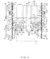
- FIG 3 is a front view illustrating the sheet bundle conveying apparatus 306, and Figure 4 is a plan view illustrating the sheet bundle conveying apparatus 306.
- the front view is taken from the side of the paper currency bundle P conveyed by the sheet bundle conveying apparatus 306, and the plan view is taken from above.
- the sheet bundle conveying apparatus 306 according to the present embodiment is described in detail with reference to Figure 3 and Figure 4 .
- the sheet bundle conveying apparatus 306 is configured basically by applying the present invention to the conventional sheet bundle conveying apparatus described in Patent Document 1.
- the conveying path 305 is a space having a shape defined by an upper wall 501, a lower wall 502, and two side walls 503 that are separate members independent of each other, the side walls 503 being located on both sides of the upper wall 501.
- the sheet bundle conveying apparatus 306 is formed of roughly two parts, that is, a carrier 600 moved along the conveying path 305 and a driving system 650 that drives the carrier 600.
- numbers equal to or larger than 601 and smaller than 650 are given as reference signs to components of the carrier 600
- numbers equal to or larger than 651 are given as reference signs to components of the driving system 650.
- a contact side of each push-out plate 602 with the paper currency bundle P is referred to as a "front side”, and the opposite side thereof is referred to as a "back slide”.
- the direction toward the front side is referred to as a "front-side direction" (or a "push-out direction,”), and the opposite direction is referred to as a "back-side direction”.
- Each push-out plate 602 is provided with a standing piece 602a protruding toward the lower wall 502 and a standing piece 6502b protruding toward the upper wall 501. Accordingly, a groove 502b having a shape suited to that of each standing piece 602a is formed on a surface 502a of the lower wall 502 in accordance with a position of each standing piece 602a, and a groove 501b having a shape suited to that of each standing piece 602b is formed on a surface 501a of the upper wall 501 in accordance with a position of each standing piece 602b.
- 602c denotes a folded-back piece obtained by bending an upper portion of the metal plate forming the push-out plate 602. Such a folded-back piece exists also in a lower portion thereof.
- Both ends of the plate-like member 601 are bent, and a roller 613 is attached to each of the ends.
- Rails 654 having a U-shape in cross-section are attached along the conveying path 305 in parallel with the conveying direction of the paper currency bundle P.
- the roller 613 is inserted into each rail 654. With this configuration, the use of the rails 654 suppresses unsteadiness, and the carrier 600 can be moved more smoothly.
- Rollers 603 that come into contact with the surface 501a of the upper wall 501 are attached to the plate-like member 601.
- the rollers 603 are provided also in order to enable more smooth movement of the carrier 600.
- the elastic members 614 serve to suppress the carrier 600 from moving in a direction in which the two side walls 503 face each other.
- a plurality of cut-out parts 601a are provided at both the ends of the plate-like member 601.
- the cut-out parts 601a are provided in order to transmit power by means of bosses 651a protruding from each driving roller 651.
- One or two pulleys 652 are attached to a shaft 655 coupled to each driving roller 651.
- a timing belt 653 is provided in a tense state between the pulleys 652 adjacent in the conveying direction.
- power from a power source for example, stepping motor
- the driving roller 651 is rotated by the power thus transmitted, and this rotation causes a change in position of the bosses 651a of the driving roller 651.
- the power is transmitted to the carrier 600 along with this change in position, so that the carrier 600 is moved.
- the bosses 651a alternately repeat entrance into and exit from the cut-out parts 601a.
- the power is transmitted via the bosses 651a during a period between the entrance into and the exit from the cut-out parts 601a.
- the configuration of the above-mentioned part is basically the same as that of the conventional sheet bundle conveying apparatus described in Patent Document 1.
- a gap (space) exists between a lower end of each push-out plate 612 and the surface 502a of the lower wall 502, and a gap (space) exists also between each cut-out piece 612a and each groove 502b.
- the paper currency is thin and flexible, and thus can enter any gap.
- the carrier 600 is used not only for conveying the paper currency bundle P along the conveying path 305 but also for appropriately positioning the paper currency bundle P conveyed from the input/output apparatus 200, in the feeding unit 301.
- FIG. 5 is a view for describing a behavior of an impeller 611 at the time of conveying the paper currency bundle P.
- the impeller 611 is provided on a rear side of each of the push-out plates 602 other than the push-out plate 602 located at the center.
- the impeller 611 is configured as a structure in which a plurality of elastic members 611a protruding along the radial direction are provided at a given interval in the circumferential direction, and the impeller 611 is rotatably supported so that the elastic member 611a located at a lower portion comes into contact with the surface 502a of the lower wall 502.
- the first and second elastic members 611a both serve as resistance (barrier) to an invasion of part of the paper currencies from the gap.
- the first elastic member 611a suppresses the paper currency from invading on the rear side of the push-out plate 602 from the gap
- the second elastic member 611a suppresses the paper currency that have entered from the gap from invading a deeper portion. Accordingly, the impeller 611 can suppress the paper currency from entering from the gap, without being rotated. This means that the conveyed paper currency bundle P can be positioned more appropriately in the feeding unit 101, that is, the paper currency bundle P in a more aligned state can be blocked with a higher accuracy.
- the paper currency that has entered from the gap is sandwiched between the second elastic member 611a and the surface 502a, and the second elastic member 611a applies a force in the push-out direction from the gap using a frictional force. Accordingly, the paper currency that has entered from the gap can be put at a more appropriate position, that is, can be more aligned with other paper currencies.
- a force corresponding to the number (weight) of the paper currencies in the paper currency bundle P is applied to the paper currency that has entered from the gap. This force hinders the paper currency to which the second elastic member 611a applies the frictional force, from returning to the appropriate position. From this, the force that is applied by the other paper currencies to the paper currency to which the frictional force is appliedmaybe reduced. This canbe achieved, for example, in the following manner.
- Another impeller is provided at a portion that comes into contact with the paper currency bundle P, and the impeller is rotated in the same direction as the arrow illustrated in Figure 5 , whereby a force in a lifting direction is applied to especially a lower portion of the paper currency bundle P. If such a force is applied, paper currencies not being aligned among the paper currencies that have not entered from the gap can be more appropriately aligned along a surface of the push-out plate 602 during the conveyance.
- rollers 604 that come into contact with the surface 502a are provided to the carrier 600.
- the rollers 604 serve as a power source for rotating the impeller 611.
- the reason why the power source is provided to the carrier 600 in this manner is to suppress the configuration from being complicated by transmitting the power for rotating the impeller 611 from the outside.
- the two rollers 604 are respectively attached to both ends of a shaft 605.
- Gears 606 are attached to the shaft 605. With this configuration, the gears 606 are rotated by rotation of the rollers 604 in the same direction, and this rotation is transmitted to gears 607 respectively meshed with the gears 606.
- Pulleys 608 are attached to a shaft 621 to which the gears 607 are attached.
- pulleys 610 are attached to a shaft 612, and a timing belt 609 is provided in a tense state between each pulley 608 and each pulley 610.
- each impeller 611 is rotated in the opposite direction to the arrow direction illustrated in Figure 5 . This rotation is not desirable because a force is applied to the paper currency that has entered from the gap, in a direction in which the paper currencies enter a deeper portion.
- the rotation in the opposite direction can be avoided by, for example, adopting a one-way clutch structure in which the gears 607 are rotated in only one direction.
- a configuration of a part A in Figure 4 is modified to that as illustrated in Figure 6 , even when the carrier 600 is moved in the back-side direction, the impeller 611 can be rotated in the arrow direction illustrated in Figure 5 .
- pulleys 631 and 632 are further attached to shafts 605 and 621, respectively, and a timing belt 633 is provided in a tense state between the pulleys 631 and 632.
- the one-way clutch structure is adopted for, for example, the pulley 632 in addition to the gear 607.
- the gear 607 and the pulley 632 are rotated in only arrow directions respectively illustrated in Figure 6 .
- the impeller 611 is rotated always in only an arrow direction illustrated in Figure 6 irrespective of the moving direction of the carrier 600. With this configuration, even after the conveyance, a force can be applied in the push-out direction to the paper currency that has entered from the gap.
- the rollers 604 that are rotated along with the movement of the carrier 600 are used as the power source for the impellers 611, but a motor or the like may be used as the power source.
- the impellers 611 are used for two purposes of: suppressing the paper currency from invading from the gap; and eliminating the paper currency that has invaded from the gap, but may be used for, for example, only the latter purpose.
- the invasion of the paper currency from the gap may be suppressed by providing an elastic member so as to block the gap.
- a component (member) used for suppressing the paper currency from entering from the gap is not limited to the impeller.
- the configuration of the carrier 600 including the push-out plates 602 is not limited to the present embodiment.
- the paper sheet handling apparatus is not limited to an apparatus that handles paper currencies, such as the ATM.
- the elastic members 611a of each impeller 611 come into contact with the paper currency that has entered from the gap (space) generated between the lower end of each push-out plate 612 and the surface 502a of the lower wall 502, and apply the frictional force to the paper currency. Because the gap is extremely small, the elastic members 611a come into contact with a portion of the paper currency in most cases, the portion having passed through the gap from the paper currency bundle P and entered on a deeper side of the push-out plate 612 (an inner side of the carrier 600). Owing to the gap, the frictional force applied by the elastic members 611a to the paper currency acts so as to push out the paper currency toward the paper currency bundle P.
- the paper currency to which this frictional force is applied can be expected to change to a more appropriate state. If the number thereof is large, however, the paper currency to which the elasticmembers 611a apply the frictional force cannot be expected too much to change to a more appropriate state, due to a frictional force generated between the paper currencies. Accordingly, the following modification may be made. Another embodiment in which the modification is made is specifically described with reference to Figure 7 and Figure 8 .
- Figure 7 is a front view illustrating a sheet bundle conveying apparatus according to the another embodiment
- Figure 8 is a view for describing a behavior of an impeller according to the another embodiment.
- Only a modified part according to the another embodiment is described with reference to Figure 7 and Figure 8 . From this, component that is the same or basically the same as the above-mentioned embodiment is denoted the same reference sign.
- a cut-out part 602d that is an opening is provided in a lower portion of each push-out plate 612.
- the cut-out part 602d is provided in a portion opposed to each impeller 611. With this configuration, the leading ends of the elastic members 611a enter the cut-out part 602a during rotation of the impeller 611.
- the cut-out part 602d enables the elastic members 611a to be in contact with the paper currency bundle P for a longer time in a longer distance range than the gap generated between the lower end of each push-out plate 612 and the surface 502a of the lower wall 502. Because the elastic members 611a can be in contact in the longer distance range, as illustrated in Figure 8 , the elastic members 611a not only apply the frictional force to the paper currency in the push-out direction toward the paper currency bundle P, but also apply a force in a direction in which the paper currency bundle P is lifted upward. The force in the lifting direction reduces frictional forces generated between the paper currency that has entered the gap and the paper currencies in contact therewith. Accordingly, the paper currency to which the elastic members 611a apply the frictional force can be more reliably brought into an appropriate state.
- the force in the direction in which the paper currency bundle P is lifted upward can also be applied by providing a groove like the groove 502b in the lower wall 502, instead of providing the cut-out part 602d in the push-out plate 612.
- a groove or the cut-out part 602d does not necessarily need to be provided in all the impellers 611. That is, both of the impellers 611 provided with the groove or the cut-out part 602d and the impellers 611 not provided therewith may exist. In the case where both types of the impellers 611 exist, it is desirable to decide a shape, arrangement, and the like for each impeller 611 depending on whether or not the impeller 611 is provided with the groove or the cut-out part 602d.
Landscapes
- Engineering & Computer Science (AREA)
- Mechanical Engineering (AREA)
- Physics & Mathematics (AREA)
- General Physics & Mathematics (AREA)
- Pile Receivers (AREA)
- Discharge By Other Means (AREA)
- Sheets, Magazines, And Separation Thereof (AREA)
- Feeding Of Articles By Means Other Than Belts Or Rollers (AREA)
Abstract
Description
- The present invention relates to a technique of conveying a paper sheet bundle in which one or more paper sheets are separably stacked, in a direction crossing the stacking direction of the paper sheets along a conveying path.
- Paper sheet handling apparatuses that handle paper sheets are widely prevalent in the society. For example, paper sheet handling apparatuses that handle paper currencies as the paper sheets are widely prevalent as automated machine such as cash processors used in teller operations, automatic depositors (AD), or automatic teller machines (ATM).
- A large part of the paper sheet handling apparatuses are configured to convey the paper sheets one by one. In recent years, some paper sheet handling apparatuses with a sheet bundle conveying apparatus mounted thereon have been put into commercial reality, the sheet bundle conveying apparatus conveying a paper sheet bundle in which one or more paper sheets are separably stacked, in a direction crossing the stacking direction of the paper sheets. A conventional sheet bundle conveying apparatus (paper sheet handling apparatus) is described in, for example,
Patent Document 1. In the conventional sheet bundle conveying apparatus described inPatent Document 1, a carrier including a plurality of contact members (plates) for coming into contact with a paper sheet bundle to push the paper sheet bundle is moved on a conveying path, whereby the paper sheet bundle is conveyed. -
Figure 1 is a view for describing the conventional sheet bundle conveying apparatus described inPatent Document 1. InFigure 1 , acarrier 10 is illustrated from the side of a paper sheet bundle P to be conveyed. 20 denotes the conveying path, and theconveying path 20 is defined by a space formed between an upper wall 71 and a lower wall 72. - In a configuration of the
carrier 10, five push-outplates 12 are attached to a plate-like member 11 produced by bending a metal plate. With this configuration, when thecarrier 10 is moved in a direction toward the paper sheet bundle P, the paper sheet bundle P is conveyed while being pushed by the push-outplates 12. - A standing
piece 12a protruding downward is provided to a lower portion of each push-outplate 12, that is, alower wall 22 side thereof. Similarly, a standingpiece 12b protruding upward is provided to an upper portion of each push-outplate 12, that is, anupper wall 21 side thereof. Accordingly, agroove 22a having a shape for housing each standingpiece 12a is formed on a conveyingpath 20 side surface of thelower wall 22, and similarly, agroove 21a having a shape for housing each standingpiece 12b is formed on a conveyingpath 20 side surface of theupper wall 21. - The push-out
plates 12 each need to avoid contact with thelower wall 22 and theupper wall 21. The paper sheet bundle P between thelower wall 22 and theupper wall 21 is conveyed with a bottom thereof being in contact with thelower wall 22. Depending on the number of paper sheets in the paper sheet bundle P, a state of each paper sheet, and the like, the topmost paper sheet may come into contact with theupper wall 21. This is because, if the number of paper sheets is large, the total thickness (hereinafter, the "thickness" is used to refer to the width in the stacking direction of the paper sheets in the stacking direction of the paper sheets, unless otherwise defined) is large, and even if the number of paper sheets is small, if a folded paper sheet exists, the total thickness may be increased by the folded paper sheet. For this reason, the standingpiece 12a and thegroove 22a, and the standingpiece 12b and thegroove 21a are provided in order to prevent the paper sheets from entering a gap between each push-out plate 14 and thelower wall 22 and a gap between each push-out plate 14 and theupper wall 21. InFigure 1 , L1 denotes the gap between each push-out plate 14 and thelower wall 22, and L4 denotes the gap between the push-out plate 14 and theupper wall 21. -
- Patent Document 1: Japanese Patent Laid-Open No.
2005-255407 - Patent Document 2: Japanese Utility Model Laid-Open No.
07-965 - Patent Document 3: Japanese Patent Laid-Open No.
09-151009 - Patent Document 4: Japanese Patent Laid-Open No.
07-172710 - The paper sheets in the paper sheet bundle P to be conveyed by the
carrier 10 are not necessarily appropriately stacked. Some of the paper sheets may have a sticking-out portion in some cases. If the paper sheet having such a sticking-out portion exist in a lower portion of the paper sheet bundle P, part of the sticking-out portion may enter the gap L1. As illustrated inFigure 1 , a gap L2 and a gap L3 may also exist between the standingpiece 12a and thegroove 22a. The gap L2 extends in an orthogonal direction (hereinafter, "horizontal direction") orthogonal to the stacking direction of the paper sheets, and the gap L3 extends in the stacking direction. The paper sheets may also enter the gap L2 or L3. - Paper sheets located at the lower portion receive the weight of paper sheets located thereon. Accordingly, unlike paper sheets located at an upper portion of the paper sheet bundle P, the paper sheets located at the lower portion tend to have a stronger force for maintaining an original state thereof. For this reason, a sticking-out portion of the paper sheets located at the lower portion more easily enters any of the gaps L1 to L3 (hereinafter, collectively referred to as "gap L").
- The paper sheet that has partially entered the gap (space) L is stacked in an inappropriate state, and thus needs to be brought into a more appropriate state. Unfortunately, the placement of the paper sheet that has partially entered the gap L is less likely to be improved into a more appropriate state during the conveyance. This is because frictions are caused between the respective members of the push-out
plates 12 and thelower wall 22 that define the gap L. When thecarrier 10 is moved back after the conveyance, these frictions may bring the paper sheet that has partially entered the gap L, into a worse state (less aligned state). - The paper sheets not being aligned may cause not only a paper jam but also damage of the paper sheets in some cases. In view of the above, assuming that all paper sheets to be conveyed are not appropriately aligned, it is important to suppress a portion of the paper sheets not being aligned from entering the gap L between the members that come into contact with the paper sheet bundle.
- It is an object of the present invention to provide a sheet bundle conveying apparatus that suppresses paper sheet constituting a paper sheet bundle to be conveyed getting into a gap between members that come into contact with the paper sheet bundle, and a paper sheet handling apparatus with the sheet bundle conveying apparatus mounted thereon.
- According to a configuration to which the present invention is applied, a carrier includes one or more contact members that come into contact with a paper sheet bundle in which one or more paper sheets are stacked, to push the paper sheet bundle, and the paper sheet bundle is conveyed by the carrier along a conveying path. Suppressing unit that suppresses the paper sheet constituting the paper sheet bundle from passing through a gap existing between a constituent member and the contact members to enter on an inner side of the carrier, the constituent member forming a space of the conveying path, the paper sheet bundle pushed by the carrier coming into contact with the constituent member.
- The application of the present invention can suppress paper sheet constituting a paper sheet bundle to be conveyed from entering a gap between members that come into contact with the paper sheet bundle, for example, between a contact member and a member forming a space of a conveying path. Accordingly, the paper sheet bundle can be brought into a more appropriate state, that is, into a state where the paper sheets are more aligned.
-
-
Figure 1 is a view for describing a conventional sheet bundle conveying apparatus described inPatent Document 1. -
Figure 2 is a schematic cross-sectional view illustrating an automatic teller machine (ATM) with a sheet bundle conveying apparatus mounted thereon according to the present embodiment. -
Figure 3 is a front view illustrating the sheet bundle conveying apparatus according to the present embodiment. -
Figure 4 is a plan view illustrating the sheet bundle conveying apparatus according to the present embodiment. -
Figure 5 is a view for describing a behavior of an impeller at the time of conveying a paper currency bundle. -
Figure 6 is a view for describing a modified example of a configuration of a part A inFigure 4 . -
Figure 7 is a front view illustrating a sheet bundle conveying apparatus according to another embodiment. -
Figure 8 is a view for describing a behavior of an impeller according to the another embodiment. - The preferred embodiments of the present invention will be explained in detail below with reference to the drawings.
Figure 2 is a schematic cross-sectional view illustrating an automatic teller machine (ATM) with a sheet bundle conveying apparatus mounted thereon according to the present embodiment. A paper sheet handling apparatus according to the present embodiment, on which the sheet bundle conveying apparatus is mounted, is implemented as anATM 100 that handles paper currencies as paper sheets. - As illustrated in
Figure 2 , theATM 100 includes: a money deposit/withdrawal apparatus 200 that receives or delivers one or more paper currencies stacked into a paper currency bundle P; anupper apparatus 300 that delivers the paper currency bundle P between the money deposit/withdrawal unit 200; and alower apparatus 400 that houses the received or deliverable paper currencies. - The money deposit/
withdrawal apparatus 200 conveys the paper currency bundle P inserted by a customer from a money deposit/withdrawal port 201, while maintaining the state of the paper currency bundle P when being inserted, to theupper apparatus 300. The money deposit/withdrawal apparatus 200 receives the paper currency bundle P to be delivered or returned from theupper apparatus 300, and conveys received paper currency bundle P to the money deposit/withdrawal port 201. Hereinafter, configurations and behaviors are described mainly assuming the case where the customer deposits money. - The paper currency bundle P from the money deposit/
withdrawal apparatus 200 is conveyed to afeeding unit 301 of theupper apparatus 300. More specifically, the paper currency bundle P is conveyed to a lifting stage 101a of thefeeding unit 301. The lifting stage 101a is movable in the up-down direction, and is moved downward after the paper currency bundle P is conveyed thereto. As a result, the paper currencies constituting the paper currency bundle P are fed and conveyed one by one by a feeding mechanism 101c provided below the feeding unit 101. A pusher 101b provided above the lifting stage 101a serves to apply an appropriate pressure to the paper currency bundle P on the lifting stage 101a. The pusher 101b is movable in the up-down direction so as to enable such pressure application. - Each paper currency fed from the feeding unit 101 is checked by a paper currency checking unit 102. In this checking, whether or not the paper currency is a genuine banknote is determined, and the money type of the genuine banknote is identified. A counterfeit paper currency, an unidentifiable paper currency, or a damaged paper currency is determined as an abnormal banknote.
- The
upper apparatus 300 is provided with three rejectboxes 307 to 309. Theupper apparatus 300 is provided with anescrow unit 303 and areservoir unit 304 for temporarily housing the paper currencies inserted by the customer. A paper currency determined as a genuine banknote by the checking is conveyed to theescrow unit 303 using switchingnails 311 and 313, and a paper currency determined as an abnormal banknote is conveyed to thereservoir unit 304 using the switchingnails 311 and 313. - The
escrow unit 303 and thereservoir unit 304 are each provided with a stage movable in the up-down direction. After the stage is lifted, the paper currencies (paper currency bundle P) housed in each of theescrow unit 303 and thereservoir unit 304 are conveyed to the feeding unit 101 or the input/output apparatus 200 through a conveyingpath 305 by a sheetbundle conveying apparatus 306. At the time of depositing money, the paper currencies are conveyed to the feeding unit 101 if the customer gives, at the end, an instruction to deposit the money, and are conveyed to the input/output apparatus 200 if the customer gives an instruction to cancel the operation. The present embodiment is implemented as the sheetbundle conveying apparatus 306. - The paper currencies in the paper currency bundle P conveyed to the feeding unit 101 are fed one by one to be checked again similarly to the above. A paper currency determined as an abnormal banknote by the checking is conveyed and housed into any of the
reject boxes 307 to 309 using switchingnails lower apparatus 400. - Four paper
currency recycling cassettes 401 are mounted on thelower apparatus 400 in order to house the paper currencies on money type basis. Eachcassette 401 is provided with a feeding/conveyingmechanism 402 for feeding the paper currencies one by one and housing the same inside of thecassette 401. In addition, two switchingnails cassette 401. With this configuration, each paper currency is conveyed and housed into thecassette 401 corresponding to the money type identified by the checking. -
Figure 3 is a front view illustrating the sheetbundle conveying apparatus 306, andFigure 4 is a plan view illustrating the sheetbundle conveying apparatus 306. The front view is taken from the side of the paper currency bundle P conveyed by the sheetbundle conveying apparatus 306, and the plan view is taken from above. Next, the sheetbundle conveying apparatus 306 according to the present embodiment is described in detail with reference toFigure 3 andFigure 4 . The sheetbundle conveying apparatus 306 is configured basically by applying the present invention to the conventional sheet bundle conveying apparatus described inPatent Document 1. - As illustrated in
Figure 3 , the conveyingpath 305 is a space having a shape defined by anupper wall 501, alower wall 502, and twoside walls 503 that are separate members independent of each other, theside walls 503 being located on both sides of theupper wall 501. The sheetbundle conveying apparatus 306 is formed of roughly two parts, that is, acarrier 600 moved along the conveyingpath 305 and adriving system 650 that drives thecarrier 600. InFigure 3 andFigure 4 , numbers equal to or larger than 601 and smaller than 650 are given as reference signs to components of thecarrier 600, and numbers equal to or larger than 651 are given as reference signs to components of thedriving system 650. - In a configuration of the
carrier 600, fives push-outplates 602 that come into contact with the paper currency bundle P when being conveyed are provided on an opposed side of a plate-like member 601 to the paper currency bundle P, the plate-like member 601 being produced by bending a metal plate punched into a predetermined shape. Hereinafter, for convenience, a contact side of each push-out plate 602 with the paper currency bundle P is referred to as a "front side", and the opposite side thereof is referred to as a "back slide". The direction toward the front side is referred to as a "front-side direction" (or a "push-out direction,"), and the opposite direction is referred to as a "back-side direction". - Each push-
out plate 602 is provided with a standingpiece 602a protruding toward thelower wall 502 and a standing piece 6502b protruding toward theupper wall 501. Accordingly, agroove 502b having a shape suited to that of each standingpiece 602a is formed on asurface 502a of thelower wall 502 in accordance with a position of each standingpiece 602a, and agroove 501b having a shape suited to that of each standingpiece 602b is formed on asurface 501a of theupper wall 501 in accordance with a position of each standingpiece 602b. 602c denotes a folded-back piece obtained by bending an upper portion of the metal plate forming the push-out plate 602. Such a folded-back piece exists also in a lower portion thereof. - Both ends of the plate-
like member 601 are bent, and aroller 613 is attached to each of the ends.Rails 654 having a U-shape in cross-section are attached along the conveyingpath 305 in parallel with the conveying direction of the paper currency bundle P. Theroller 613 is inserted into eachrail 654. With this configuration, the use of therails 654 suppresses unsteadiness, and thecarrier 600 can be moved more smoothly. -
Rollers 603 that come into contact with thesurface 501a of theupper wall 501 are attached to the plate-like member 601. Therollers 603 are provided also in order to enable more smooth movement of thecarrier 600. - In addition, totally four
elastic members 614 that come into contact with theside walls 503 are attached to the plate-likemember 601. Theelastic members 614 serve to suppress thecarrier 600 from moving in a direction in which the twoside walls 503 face each other. - A plurality of cut-out
parts 601a are provided at both the ends of the plate-like member 601. The cut-outparts 601a are provided in order to transmit power by means ofbosses 651a protruding from each drivingroller 651. - One or two
pulleys 652 are attached to ashaft 655 coupled to each drivingroller 651. Atiming belt 653 is provided in a tense state between thepulleys 652 adjacent in the conveying direction. With this configuration, power from a power source (for example, stepping motor), which is not particularly illustrated, is transmitted to each drivingroller 651 via the timing belt. The drivingroller 651 is rotated by the power thus transmitted, and this rotation causes a change in position of thebosses 651a of the drivingroller 651. Then, the power is transmitted to thecarrier 600 along with this change in position, so that thecarrier 600 is moved. During the movement of thecarrier 600, thebosses 651a alternately repeat entrance into and exit from the cut-outparts 601a. The power is transmitted via thebosses 651a during a period between the entrance into and the exit from the cut-outparts 601a. - The configuration of the above-mentioned part is basically the same as that of the conventional sheet bundle conveying apparatus described in
Patent Document 1. In this configuration, as illustrated inFigure 3 , a gap (space) exists between a lower end of each push-out plate 612 and thesurface 502a of thelower wall 502, and a gap (space) exists also between each cut-out piece 612a and eachgroove 502b. The paper currency is thin and flexible, and thus can enter any gap. Thecarrier 600 is used not only for conveying the paper currency bundle P along the conveyingpath 305 but also for appropriately positioning the paper currency bundle P conveyed from the input/output apparatus 200, in thefeeding unit 301. From this fact, particularly when the paper currency bundle P is conveyed (thecarrier 600 is moved in the front-side direction) and when the conveyed paper currency bundle P comes into contact, part of paper currency sticking out of the paper currency bundle P toward thecarrier 600 may enter the gaps. In the present embodiment, the following configuration suppresses the paper currency from entering the gaps. Specific description thereof is given with additional reference toFigure 5. Figure 5 is a view for describing a behavior of animpeller 611 at the time of conveying the paper currency bundle P. - As illustrated in
Figure 3 to Figure 5 , theimpeller 611 is provided on a rear side of each of the push-outplates 602 other than the push-out plate 602 located at the center. Theimpeller 611 is configured as a structure in which a plurality ofelastic members 611a protruding along the radial direction are provided at a given interval in the circumferential direction, and theimpeller 611 is rotatably supported so that theelastic member 611a located at a lower portion comes into contact with thesurface 502a of thelower wall 502. With this configuration, as illustrated inFigure 5 , the elastic member (hereinafter, referred to as "first elastic member" for convenience) 611a that has a leading end in contact with thesurface 502a and is located closest to the push-out plate 602 fills the gap between the push-out plate 602 and thesurface 502a. The elastic member (hereinafter, referred to as "second elastic member" for convenience) 611a that is in contact with thesurface 502a and is located on the back side of the firstelastic member 611a deforms to a larger degree, and has a leading end in contact with thesurface 502a. - The first and second
elastic members 611a both serve as resistance (barrier) to an invasion of part of the paper currencies from the gap. The firstelastic member 611a suppresses the paper currency from invading on the rear side of the push-out plate 602 from the gap, and the secondelastic member 611a suppresses the paper currency that have entered from the gap from invading a deeper portion. Accordingly, theimpeller 611 can suppress the paper currency from entering from the gap, without being rotated. This means that the conveyed paper currency bundle P can be positioned more appropriately in the feeding unit 101, that is, the paper currency bundle P in a more aligned state can be blocked with a higher accuracy. - When the
impeller 611 is rotated in an arrow direction illustrated inFigure 5 , the paper currency that has entered from the gap is sandwiched between the secondelastic member 611a and thesurface 502a, and the secondelastic member 611a applies a force in the push-out direction from the gap using a frictional force. Accordingly, the paper currency that has entered from the gap can be put at a more appropriate position, that is, can be more aligned with other paper currencies. - A force corresponding to the number (weight) of the paper currencies in the paper currency bundle P is applied to the paper currency that has entered from the gap. This force hinders the paper currency to which the second
elastic member 611a applies the frictional force, from returning to the appropriate position. From this, the force that is applied by the other paper currencies to the paper currency to which the frictional force is appliedmaybe reduced. This canbe achieved, for example, in the following manner. Another impeller is provided at a portion that comes into contact with the paper currency bundle P, and the impeller is rotated in the same direction as the arrow illustrated inFigure 5 , whereby a force in a lifting direction is applied to especially a lower portion of the paper currency bundle P. If such a force is applied, paper currencies not being aligned among the paper currencies that have not entered from the gap can be more appropriately aligned along a surface of the push-out plate 602 during the conveyance. - As illustrated in
Figure 3 to Figure 5 , in the present embodiment, tworollers 604 that come into contact with thesurface 502a are provided to thecarrier 600. Therollers 604 serve as a power source for rotating theimpeller 611. The reason why the power source is provided to thecarrier 600 in this manner is to suppress the configuration from being complicated by transmitting the power for rotating theimpeller 611 from the outside. - The two
rollers 604 are respectively attached to both ends of ashaft 605.Gears 606 are attached to theshaft 605. With this configuration, thegears 606 are rotated by rotation of therollers 604 in the same direction, and this rotation is transmitted togears 607 respectively meshed with thegears 606. -
Pulleys 608 are attached to ashaft 621 to which thegears 607 are attached. Similarly to theimpellers 611,pulleys 610 are attached to ashaft 612, and atiming belt 609 is provided in a tense state between eachpulley 608 and eachpulley 610. With this configuration, as illustrated inFigure 5 , when thecarrier 600 is moving in the front-side direction (expressed by "PAPER CURRENCY BUNDLE PUSH-OUT DIRECTION" inFigure 5 ) in order to convey the paper currency bundle P, eachroller 604 and eachimpeller 611 are rotated in the opposite direction. That is, when thecarrier 600 is moving in the front-side direction, theimpeller 611 is rotated in the arrow direction illustrated inFigure 5 . As a result, when thecarrier 600 is moving in the front-side direction, a force for pushing out, from the gap, the paper currency that has entered from the gap between the push-out plate 602 and thesurface 502a (in this case, including a gap between the standingpiece 602a and thegroove 502b) is transmitted via theimpeller 611. - The above-mentioned configuration is adopted for a driving systemof the
impellers 611, that is, a unit (transmitting means) that rotates theimpellers 611 using therollers 604 as the power source. With the driving system as described above, however, when thecarrier 600 is moved in the back-side direction, eachimpeller 611 is rotated in the opposite direction to the arrow direction illustrated inFigure 5 . This rotation is not desirable because a force is applied to the paper currency that has entered from the gap, in a direction in which the paper currencies enter a deeper portion. - The rotation in the opposite direction can be avoided by, for example, adopting a one-way clutch structure in which the
gears 607 are rotated in only one direction. In addition, in the case where a configuration of a part A inFigure 4 is modified to that as illustrated inFigure 6 , even when thecarrier 600 is moved in the back-side direction, theimpeller 611 can be rotated in the arrow direction illustrated inFigure 5 . - In a configuration illustrated in
Figure 6 , pulleys 631 and 632 are further attached toshafts timing belt 633 is provided in a tense state between thepulleys pulley 632 in addition to thegear 607. With this configuration, thegear 607 and thepulley 632 are rotated in only arrow directions respectively illustrated inFigure 6 . As a result, when thecarrier 600 is moved in the front-side direction, the power transmission via thegear 607 is effective, and when thecarrier 600 is moved in the back-side direction, the power transmission via thepulley 632 is effective. Accordingly, theimpeller 611 is rotated always in only an arrow direction illustrated inFigure 6 irrespective of the moving direction of thecarrier 600. With this configuration, even after the conveyance, a force can be applied in the push-out direction to the paper currency that has entered from the gap. - Note that, in the present embodiment, the
rollers 604 that are rotated along with the movement of thecarrier 600 are used as the power source for theimpellers 611, but a motor or the like may be used as the power source. In addition, theimpellers 611 are used for two purposes of: suppressing the paper currency from invading from the gap; and eliminating the paper currency that has invaded from the gap, but may be used for, for example, only the latter purpose. The invasion of the paper currency from the gap may be suppressed by providing an elastic member so as to block the gap. Accordingly, a component (member) used for suppressing the paper currency from entering from the gap is not limited to the impeller. In this way, various modifications are possible. In addition, the configuration of thecarrier 600 including the push-outplates 602 is not limited to the present embodiment. The paper sheet handling apparatus is not limited to an apparatus that handles paper currencies, such as the ATM. - In the present embodiment, the
elastic members 611a of eachimpeller 611 come into contact with the paper currency that has entered from the gap (space) generated between the lower end of each push-out plate 612 and thesurface 502a of thelower wall 502, and apply the frictional force to the paper currency. Because the gap is extremely small, theelastic members 611a come into contact with a portion of the paper currency in most cases, the portion having passed through the gap from the paper currency bundle P and entered on a deeper side of the push-out plate 612 (an inner side of the carrier 600). Owing to the gap, the frictional force applied by theelastic members 611a to the paper currency acts so as to push out the paper currency toward the paper currency bundle P. - If the number of the paper currencies constituting the paper currency bundle P is relatively small, the paper currency to which this frictional force is applied can be expected to change to a more appropriate state. If the number thereof is large, however, the paper currency to which the elasticmembers 611a apply the frictional force cannot be expected too much to change to a more appropriate state, due to a frictional force generated between the paper currencies. Accordingly, the following modification may be made. Another embodiment in which the modification is made is specifically described with reference to
Figure 7 andFigure 8 . -
Figure 7 is a front view illustrating a sheet bundle conveying apparatus according to the another embodiment, andFigure 8 is a view for describing a behavior of an impeller according to the another embodiment. Here, only a modified part according to the another embodiment is described with reference toFigure 7 andFigure 8 . From this, component that is the same or basically the same as the above-mentioned embodiment is denoted the same reference sign. - As illustrated in
Figure 7 , in the another embodiment, a cut-outpart 602d that is an opening is provided in a lower portion of each push-out plate 612. The cut-outpart 602d is provided in a portion opposed to eachimpeller 611. With this configuration, the leading ends of theelastic members 611a enter the cut-outpart 602a during rotation of theimpeller 611. - The cut-out
part 602d enables theelastic members 611a to be in contact with the paper currency bundle P for a longer time in a longer distance range than the gap generated between the lower end of each push-out plate 612 and thesurface 502a of thelower wall 502. Because theelastic members 611a can be in contact in the longer distance range, as illustrated inFigure 8 , theelastic members 611a not only apply the frictional force to the paper currency in the push-out direction toward the paper currency bundle P, but also apply a force in a direction in which the paper currency bundle P is lifted upward. The force in the lifting direction reduces frictional forces generated between the paper currency that has entered the gap and the paper currencies in contact therewith. Accordingly, the paper currency to which theelastic members 611a apply the frictional force can be more reliably brought into an appropriate state. - The force in the direction in which the paper currency bundle P is lifted upward can also be applied by providing a groove like the
groove 502b in thelower wall 502, instead of providing the cut-outpart 602d in the push-out plate 612. Such a groove or the cut-outpart 602d does not necessarily need to be provided in all theimpellers 611. That is, both of theimpellers 611 provided with the groove or the cut-outpart 602d and theimpellers 611 not provided therewith may exist. In the case where both types of theimpellers 611 exist, it is desirable to decide a shape, arrangement, and the like for eachimpeller 611 depending on whether or not theimpeller 611 is provided with the groove or the cut-outpart 602d. -
- 305 conveying path
- 306 sheet bundle conveying apparatus
- 501 upper wall
- 501a, 502a surface
- 501b, 502b groove
- 502 lower wall
- 503 side wall
- 600 carrier
- 602 push-out plate
- 602a, 602b standing piece
- 602d cut-out part
- 604 roller
- 605, 612, 621 shaft
- 606, 607 gear
- 608, 610, 631, 632 pulley
- 609, 633 timing belt
- 611 impeller
- 611a elastic member
Claims (6)
- A sheet bundle conveying apparatus that conveys a paper sheet bundle in which one or more paper sheets are stacked, along a conveying path, comprising:a carrier including one or more contact members that come into contact with the paper sheet bundle to push the paper sheet bundle, the carrier being moved along the conveying path; andsuppressing unit that suppresses the paper sheet constituting the paper sheet bundle from passing through a gap existing between a constituent member and the contact members to enter on an inner side of the carrier, the constituent member forming a space of the conveying path, the paper sheet bundle pushed by the carrier coming into contact with the constituent member.
- The sheet bundle conveying apparatus according to claim 1, wherein
the suppressing unit includes:an impeller arranges a plurality of elastic members each having an elastic force and protruding along a radial direction are provided at a given interval in a circumferential direction; anddriving unit that rotates the impeller,the suppressing unit suppresses, when the carrier is stopped, the paper sheet from entering on the inner side of the carrier, by means of the impeller with the elastic members being in contact with the constituent member, andthe suppressing unit suppresses, when the carrier is moved, the paper sheets from entering on the inner side of the carrier, by causing the driving unit to rotate the impeller and applying a push-out force to the paper sheet via the elastic members coming into contact with portions of the paper sheet, the portions each having entered the gap. - The sheet bundle conveying apparatus according to claim 2, wherein
the contact members have an opening, and
the suppressing unit suppresses the paper sheet from entering on the inner side of the carrier, by means of the elastic members coming into contact with the paper sheets through the opening. - The sheet bundle conveying apparatus according to claim 2 or 3, wherein
the driving unit includes:a rotatable roller that comes into contact with a member existing on the conveying path; andtransmitting unit that transmits, to the impeller, rotation of the roller caused by the movement of the carrier. - The sheet bundle conveying apparatus according to claim 4, wherein
the driving unit rotates the impeller always in the same direction, when the carrier is moved. - A paper sheet handling apparatus comprising:the sheet bundle conveying apparatus according to claim 1; anda conveying path along which a paper sheet bundle is conveyed by the sheet bundle conveying apparatus.
Applications Claiming Priority (1)
| Application Number | Priority Date | Filing Date | Title |
|---|---|---|---|
| PCT/JP2009/002997 WO2011001464A1 (en) | 2009-06-29 | 2009-06-29 | Note-bundle conveying apparatus and paper-note handling device |
Publications (2)
| Publication Number | Publication Date |
|---|---|
| EP2450300A1 true EP2450300A1 (en) | 2012-05-09 |
| EP2450300A4 EP2450300A4 (en) | 2017-12-27 |
Family
ID=43410567
Family Applications (1)
| Application Number | Title | Priority Date | Filing Date |
|---|---|---|---|
| EP09846760.8A Withdrawn EP2450300A4 (en) | 2009-06-29 | 2009-06-29 | Note-bundle conveying apparatus and paper-note handling device |
Country Status (6)
| Country | Link |
|---|---|
| US (1) | US8448780B2 (en) |
| EP (1) | EP2450300A4 (en) |
| JP (1) | JP5226869B2 (en) |
| KR (1) | KR101275926B1 (en) |
| CN (1) | CN102459045B (en) |
| WO (1) | WO2011001464A1 (en) |
Families Citing this family (4)
| Publication number | Priority date | Publication date | Assignee | Title |
|---|---|---|---|---|
| JP5770387B2 (en) * | 2012-10-03 | 2015-08-26 | 富士通フロンテック株式会社 | Paper sheet handling equipment |
| CN104649063A (en) * | 2013-11-25 | 2015-05-27 | 北京航天斯达新技术装备公司 | Outgoing system applied to paper financial product |
| JP6598470B2 (en) * | 2015-02-19 | 2019-10-30 | グローリー株式会社 | Paper sheet processing equipment |
| TWI642033B (en) * | 2017-07-19 | 2018-11-21 | 鴻發國際科技股份有限公司 | Paper storage equipment |
Family Cites Families (18)
| Publication number | Priority date | Publication date | Assignee | Title |
|---|---|---|---|---|
| US3375939A (en) * | 1966-01-28 | 1968-04-02 | Harris Intertype Corp | Papercutter |
| US3790004A (en) * | 1969-01-30 | 1974-02-05 | Gen Foods Corp | Apparatus for automatically stacking material |
| US3892168A (en) * | 1974-01-14 | 1975-07-01 | Molins Machine Co Inc | Counter ejector |
| DE2511943C3 (en) * | 1975-03-19 | 1979-03-15 | Amiad Mutzarei Yiul, Hevel Korazim (Israel) | Device for storing and dispensing stacked, sheet-like material |
| JPS57501780A (en) * | 1980-10-10 | 1982-10-07 | ||
| IT1203496B (en) * | 1986-03-15 | 1989-02-15 | Womako Masch Konstr | DEVICE FOR AUTOMATICALLY INTRODUCING LAYERS OF PAPER IN A PROCESSING MACHINE |
| US5240368A (en) * | 1989-12-04 | 1993-08-31 | Diebold, Inc. | Sheet handling apparatus |
| SU1694462A1 (en) * | 1989-12-14 | 1991-11-30 | Каунасский Политехнический Институт | Device for taking single flat soft articles |
| JP2753386B2 (en) * | 1990-11-19 | 1998-05-20 | 株式会社日立製作所 | Paper sheet stacking device |
| US5205703A (en) * | 1991-05-14 | 1993-04-27 | Thermoguard Equipment, Inc. | Top sheet hold down for stacked sheet handling machine |
| JPH07965U (en) * | 1991-09-26 | 1995-01-06 | 日本電気ホームエレクトロニクス株式会社 | Paper ejection mechanism of printing device |
| JPH07965A (en) | 1993-06-17 | 1995-01-06 | Brother Ind Ltd | Ion water generator |
| JP2818105B2 (en) | 1993-12-22 | 1998-10-30 | ローレルバンクマシン株式会社 | Paper sheet storage and delivery mechanism in paper sheet depositing and dispensing machine |
| CH690100A5 (en) * | 1994-05-24 | 2000-04-28 | Bobst Sa | Auxiliary drive device for transporting sheets of paper or cardboard. |
| JP2716384B2 (en) * | 1994-11-25 | 1998-02-18 | 忠男 宇野 | Sheet bundle flat stacking device |
| JP3292013B2 (en) * | 1995-12-01 | 2002-06-17 | 富士電機株式会社 | Bill storage device |
| JP4326989B2 (en) * | 2004-03-15 | 2009-09-09 | 富士通株式会社 | Paper sheet bundle conveying device and handling device |
| DE202005000416U1 (en) * | 2005-01-07 | 2005-03-17 | Francotyp Postalia Ag | Postal items pre-pay stamping apparatus, has drive of first transport arrangement detachably connected to first drive of stamping machine |
-
2009
- 2009-06-29 EP EP09846760.8A patent/EP2450300A4/en not_active Withdrawn
- 2009-06-29 WO PCT/JP2009/002997 patent/WO2011001464A1/en not_active Ceased
- 2009-06-29 KR KR1020117031511A patent/KR101275926B1/en not_active Expired - Fee Related
- 2009-06-29 JP JP2011520665A patent/JP5226869B2/en not_active Expired - Fee Related
- 2009-06-29 CN CN200980160098.4A patent/CN102459045B/en active Active
-
2011
- 2011-12-23 US US13/336,166 patent/US8448780B2/en not_active Expired - Fee Related
Non-Patent Citations (1)
| Title |
|---|
| See references of WO2011001464A1 * |
Also Published As
| Publication number | Publication date |
|---|---|
| KR101275926B1 (en) | 2013-06-17 |
| EP2450300A4 (en) | 2017-12-27 |
| US8448780B2 (en) | 2013-05-28 |
| CN102459045A (en) | 2012-05-16 |
| CN102459045B (en) | 2015-04-01 |
| JPWO2011001464A1 (en) | 2012-12-10 |
| US20120132505A1 (en) | 2012-05-31 |
| KR20120024883A (en) | 2012-03-14 |
| WO2011001464A1 (en) | 2011-01-06 |
| JP5226869B2 (en) | 2013-07-03 |
Similar Documents
| Publication | Publication Date | Title |
|---|---|---|
| JP5196542B2 (en) | Paper sheet processing equipment | |
| US8448780B2 (en) | Sheet bundle conveying apparatus and paper sheet handling apparatus | |
| CN104837753B (en) | It is taken into carrying device, media storing storehouse and media processing apparatus | |
| RU2628510C2 (en) | Carrier transportation device and device for transaction with carrier | |
| EP3567560B1 (en) | Value note cassette | |
| AU2023266292A1 (en) | Banknote deposit-withdrawal system and architecture | |
| US6626426B2 (en) | Self-service terminal | |
| JP5209977B2 (en) | Paper sheet processing equipment | |
| JP6664245B2 (en) | Automatic change payment machine | |
| JP2015121843A (en) | Bill processor | |
| JP2018184289A (en) | Media processing apparatus and automatic transaction apparatus | |
| JP6094161B2 (en) | Media processing device | |
| CN104937643B (en) | Paper storage device, paper processing device, and paper conveying device | |
| JP5927909B2 (en) | Paper sheet conveying device and paper sheet handling device | |
| JP2007164777A (en) | Apparatus for separately storing printing paper sheets | |
| JP2005259084A (en) | Construction method of paper sheet handling apparatus and paper sheet cassette | |
| JP2019057157A (en) | Storage feeding mechanism, paper sheet processing apparatus, and paper sheet storage cassette | |
| JP2006031271A (en) | Paper sheet processor |
Legal Events
| Date | Code | Title | Description |
|---|---|---|---|
| PUAI | Public reference made under article 153(3) epc to a published international application that has entered the european phase |
Free format text: ORIGINAL CODE: 0009012 |
|
| 17P | Request for examination filed |
Effective date: 20120123 |
|
| AK | Designated contracting states |
Kind code of ref document: A1 Designated state(s): AT BE BG CH CY CZ DE DK EE ES FI FR GB GR HR HU IE IS IT LI LT LU LV MC MK MT NL NO PL PT RO SE SI SK TR |
|
| DAX | Request for extension of the european patent (deleted) | ||
| RA4 | Supplementary search report drawn up and despatched (corrected) |
Effective date: 20171127 |
|
| RIC1 | Information provided on ipc code assigned before grant |
Ipc: G07D 9/00 20060101ALI20171121BHEP Ipc: B65H 5/16 20060101AFI20171121BHEP Ipc: B65H 31/26 20060101ALI20171121BHEP Ipc: G07D 11/00 20060101ALI20171121BHEP Ipc: B65H 5/00 20060101ALI20171121BHEP Ipc: B65H 31/30 20060101ALI20171121BHEP |
|
| GRAP | Despatch of communication of intention to grant a patent |
Free format text: ORIGINAL CODE: EPIDOSNIGR1 |
|
| RIC1 | Information provided on ipc code assigned before grant |
Ipc: B65H 31/26 20060101ALI20180730BHEP Ipc: B65H 5/00 20060101ALI20180730BHEP Ipc: G07D 11/00 20060101ALI20180730BHEP Ipc: G07D 9/00 20060101ALI20180730BHEP Ipc: B65H 31/30 20060101ALI20180730BHEP Ipc: B65H 5/16 20060101AFI20180730BHEP |
|
| INTG | Intention to grant announced |
Effective date: 20180822 |
|
| STAA | Information on the status of an ep patent application or granted ep patent |
Free format text: STATUS: THE APPLICATION IS DEEMED TO BE WITHDRAWN |
|
| 18D | Application deemed to be withdrawn |
Effective date: 20190103 |