EP2450171A1 - Apparatus and method for making a tubular composite barrel - Google Patents
Apparatus and method for making a tubular composite barrel Download PDFInfo
- Publication number
- EP2450171A1 EP2450171A1 EP12000610A EP12000610A EP2450171A1 EP 2450171 A1 EP2450171 A1 EP 2450171A1 EP 12000610 A EP12000610 A EP 12000610A EP 12000610 A EP12000610 A EP 12000610A EP 2450171 A1 EP2450171 A1 EP 2450171A1
- Authority
- EP
- European Patent Office
- Prior art keywords
- door
- tool
- fixed segment
- inner skin
- doors
- Prior art date
- Legal status (The legal status is an assumption and is not a legal conclusion. Google has not performed a legal analysis and makes no representation as to the accuracy of the status listed.)
- Granted
Links
- 239000002131 composite material Substances 0.000 title claims abstract description 64
- 238000000034 method Methods 0.000 title claims description 30
- 238000000465 moulding Methods 0.000 claims abstract description 46
- 238000007789 sealing Methods 0.000 claims abstract description 23
- 239000000565 sealant Substances 0.000 claims description 22
- 239000004593 Epoxy Substances 0.000 claims description 4
- 229910000831 Steel Inorganic materials 0.000 claims description 3
- 239000010959 steel Substances 0.000 claims description 3
- 239000011324 bead Substances 0.000 description 13
- 239000004744 fabric Substances 0.000 description 10
- 239000000463 material Substances 0.000 description 9
- 229920006254 polymer film Polymers 0.000 description 8
- 229920006284 nylon film Polymers 0.000 description 7
- 230000000712 assembly Effects 0.000 description 6
- 238000000429 assembly Methods 0.000 description 6
- 229920006255 plastic film Polymers 0.000 description 5
- 239000002985 plastic film Substances 0.000 description 5
- 238000002360 preparation method Methods 0.000 description 4
- 229910001374 Invar Inorganic materials 0.000 description 2
- ZCDOYSPFYFSLEW-UHFFFAOYSA-N chromate(2-) Chemical compound [O-][Cr]([O-])(=O)=O ZCDOYSPFYFSLEW-UHFFFAOYSA-N 0.000 description 2
- 238000005056 compaction Methods 0.000 description 2
- 230000013011 mating Effects 0.000 description 2
- 244000261422 Lysimachia clethroides Species 0.000 description 1
- 239000004677 Nylon Substances 0.000 description 1
- 239000000853 adhesive Substances 0.000 description 1
- 230000001070 adhesive effect Effects 0.000 description 1
- 239000003795 chemical substances by application Substances 0.000 description 1
- 238000004140 cleaning Methods 0.000 description 1
- 238000001816 cooling Methods 0.000 description 1
- 238000010438 heat treatment Methods 0.000 description 1
- 230000000977 initiatory effect Effects 0.000 description 1
- 239000002184 metal Substances 0.000 description 1
- 229920001778 nylon Polymers 0.000 description 1
- 239000004033 plastic Substances 0.000 description 1
- 238000003825 pressing Methods 0.000 description 1
- 238000000926 separation method Methods 0.000 description 1
- 239000002904 solvent Substances 0.000 description 1
Images


Classifications
-
- B—PERFORMING OPERATIONS; TRANSPORTING
- B29—WORKING OF PLASTICS; WORKING OF SUBSTANCES IN A PLASTIC STATE IN GENERAL
- B29C—SHAPING OR JOINING OF PLASTICS; SHAPING OF MATERIAL IN A PLASTIC STATE, NOT OTHERWISE PROVIDED FOR; AFTER-TREATMENT OF THE SHAPED PRODUCTS, e.g. REPAIRING
- B29C70/00—Shaping composites, i.e. plastics material comprising reinforcements, fillers or preformed parts, e.g. inserts
- B29C70/04—Shaping composites, i.e. plastics material comprising reinforcements, fillers or preformed parts, e.g. inserts comprising reinforcements only, e.g. self-reinforcing plastics
- B29C70/28—Shaping operations therefor
- B29C70/40—Shaping or impregnating by compression not applied
- B29C70/42—Shaping or impregnating by compression not applied for producing articles of definite length, i.e. discrete articles
- B29C70/44—Shaping or impregnating by compression not applied for producing articles of definite length, i.e. discrete articles using isostatic pressure, e.g. pressure difference-moulding, vacuum bag-moulding, autoclave-moulding or expanding rubber-moulding
-
- B—PERFORMING OPERATIONS; TRANSPORTING
- B29—WORKING OF PLASTICS; WORKING OF SUBSTANCES IN A PLASTIC STATE IN GENERAL
- B29C—SHAPING OR JOINING OF PLASTICS; SHAPING OF MATERIAL IN A PLASTIC STATE, NOT OTHERWISE PROVIDED FOR; AFTER-TREATMENT OF THE SHAPED PRODUCTS, e.g. REPAIRING
- B29C33/00—Moulds or cores; Details thereof or accessories therefor
- B29C33/44—Moulds or cores; Details thereof or accessories therefor with means for, or specially constructed to facilitate, the removal of articles, e.g. of undercut articles
- B29C33/48—Moulds or cores; Details thereof or accessories therefor with means for, or specially constructed to facilitate, the removal of articles, e.g. of undercut articles with means for collapsing or disassembling
- B29C33/485—Moulds or cores; Details thereof or accessories therefor with means for, or specially constructed to facilitate, the removal of articles, e.g. of undercut articles with means for collapsing or disassembling cores or mandrels
-
- B—PERFORMING OPERATIONS; TRANSPORTING
- B29—WORKING OF PLASTICS; WORKING OF SUBSTANCES IN A PLASTIC STATE IN GENERAL
- B29L—INDEXING SCHEME ASSOCIATED WITH SUBCLASS B29C, RELATING TO PARTICULAR ARTICLES
- B29L2031/00—Other particular articles
- B29L2031/748—Machines or parts thereof not otherwise provided for
- B29L2031/7504—Turbines
-
- Y—GENERAL TAGGING OF NEW TECHNOLOGICAL DEVELOPMENTS; GENERAL TAGGING OF CROSS-SECTIONAL TECHNOLOGIES SPANNING OVER SEVERAL SECTIONS OF THE IPC; TECHNICAL SUBJECTS COVERED BY FORMER USPC CROSS-REFERENCE ART COLLECTIONS [XRACs] AND DIGESTS
- Y10—TECHNICAL SUBJECTS COVERED BY FORMER USPC
- Y10T—TECHNICAL SUBJECTS COVERED BY FORMER US CLASSIFICATION
- Y10T156/00—Adhesive bonding and miscellaneous chemical manufacture
- Y10T156/10—Methods of surface bonding and/or assembly therefor
- Y10T156/1002—Methods of surface bonding and/or assembly therefor with permanent bending or reshaping or surface deformation of self sustaining lamina
- Y10T156/1028—Methods of surface bonding and/or assembly therefor with permanent bending or reshaping or surface deformation of self sustaining lamina by bending, drawing or stretch forming sheet to assume shape of configured lamina while in contact therewith
- Y10T156/103—Encasing or enveloping the configured lamina
-
- Y—GENERAL TAGGING OF NEW TECHNOLOGICAL DEVELOPMENTS; GENERAL TAGGING OF CROSS-SECTIONAL TECHNOLOGIES SPANNING OVER SEVERAL SECTIONS OF THE IPC; TECHNICAL SUBJECTS COVERED BY FORMER USPC CROSS-REFERENCE ART COLLECTIONS [XRACs] AND DIGESTS
- Y10—TECHNICAL SUBJECTS COVERED BY FORMER USPC
- Y10T—TECHNICAL SUBJECTS COVERED BY FORMER US CLASSIFICATION
- Y10T156/00—Adhesive bonding and miscellaneous chemical manufacture
- Y10T156/10—Methods of surface bonding and/or assembly therefor
- Y10T156/1002—Methods of surface bonding and/or assembly therefor with permanent bending or reshaping or surface deformation of self sustaining lamina
- Y10T156/1028—Methods of surface bonding and/or assembly therefor with permanent bending or reshaping or surface deformation of self sustaining lamina by bending, drawing or stretch forming sheet to assume shape of configured lamina while in contact therewith
- Y10T156/1033—Flexible sheet to cylinder lamina
-
- Y—GENERAL TAGGING OF NEW TECHNOLOGICAL DEVELOPMENTS; GENERAL TAGGING OF CROSS-SECTIONAL TECHNOLOGIES SPANNING OVER SEVERAL SECTIONS OF THE IPC; TECHNICAL SUBJECTS COVERED BY FORMER USPC CROSS-REFERENCE ART COLLECTIONS [XRACs] AND DIGESTS
- Y10—TECHNICAL SUBJECTS COVERED BY FORMER USPC
- Y10T—TECHNICAL SUBJECTS COVERED BY FORMER US CLASSIFICATION
- Y10T156/00—Adhesive bonding and miscellaneous chemical manufacture
- Y10T156/10—Methods of surface bonding and/or assembly therefor
- Y10T156/1002—Methods of surface bonding and/or assembly therefor with permanent bending or reshaping or surface deformation of self sustaining lamina
- Y10T156/1036—Bending of one piece blank and joining edges to form article
- Y10T156/1038—Hollow cylinder article
Definitions
- the present invention is directed to a 360° tool for making a 360° composite tubular structure, the tool being adjustable between a molding position and a non-molding position.
- the tool comprises a base and at least one fixed segment that is fixed relative to the base, the at least one fixed segment having a first circumferential end and a second circumferential end.
- the tool further comprises a first door having a first circumferential end hingedly connected to the first circumferential end of the at least one fixed segment, a second door hingedly connected to the first door and configured to fit between the first door and the second circumferential end of the fixed segment to thereby complete the 360° circumferential extent of the tool.
- the second door wear plates 176a, 176b, 176c have differing lengths due to the varying degree of travel experienced by the wheel assemblies when the second door 220 is operated. However, since the second door 220 opens wider than the first door, the lengths of the second door wear plates 176a, 176b, 176c are longer than the corresponding lengths of the first door wear plates 170a, 170b, 170c.
- the spherical wheel assemblies 576a, 576b, 576c and the second door wear plates 176a, 176b, 176c allow an operator to manually move the second door 220 along an arcuate path by simply pushing or pulling on one or more door handles 525. It is understood that the wear plates 176a, 176b, 176c are replaceable.
- the tool 100 is adjusted to the molding position and composite material is applied in a pre-determined horizontal band between the upper and lower edges of the fixed segment 200 and the doors 210, 220, 230. After the composite material has been applied, it is covered with plastic film and vacuum sealed. The plastic film is placed on the outside of the tool over the composite material, and also on the inside of the tool over the interface regions between the various segments 200, 210, 220, 230.
- a first portion of polymer film such as a nylon film
- This first portion of film is a single piece that extends around the entire circumference of the tool and is overlapped in the circumferential direction by 2-3 centimeters or so, the overlapping ends secured by an axially extending piece of chromate tape.
- This first portion of nylon film is of sufficient height to contact the upper and lower beads.
- the upper edge of the nylon film extends above the upper bead around the entire circumference of the tool, while the lower edge of the first portion of nylon film extends below the lower bead around the entire circumference of the tool.
- the tool surface is prepared, in a known manner.
- the tool surface preparation process 802 entails: interface areas.
- a first portion of polymer film is wrapped around the circumference of the tool such that it contacts and seals against the upper lower beads of sealant tape in the manner described above.
- second portions of polymer film may optionally be applied to form a seal with a corresponding one of the tape beads that extend around each interface area on the inside surface of the tool, in the manner described above. In such case, the first portion of polymer film sealingly engages the second portions of polymer film at each notch pair;
Landscapes
- Engineering & Computer Science (AREA)
- Mechanical Engineering (AREA)
- Chemical & Material Sciences (AREA)
- Composite Materials (AREA)
- Moulding By Coating Moulds (AREA)
Abstract
Description
- None.
- The present invention is related to a method and apparatus for making tubular composite articles, such as an acoustic liner for an aircraft nacelle.
- An acoustic inlet barrel for a nacelle inlet may comprise a number of layers, including a perforated inner skin, an acoustic core, and an impervious outer skin. Typically, the inner skin is formed from sectors that are bolted together at axially extending seams. Ideally, however, the perforated skin has no internal seams or other features which may degrade the acoustic performance of the barrel.
-
U.S. Patent No. 7,125,237 discloses a tool for molding an air intake, and more specifically for forming a one-piece inner skin having no internal seams. The tool comprises a mandrel having four arcuate sectors, a fixed sector that does not move during normal operation to the tool, two movable articulated sectors each hingedly connected to either side of the first sector; and a movable key sector which is independent from the other sectors and insertable between the articulated sectors. By virtue of the hinges, the articulated sectors remain connected to the fixed sector and cannot be separated therefrom. Locks are provided to secure the key sector to the articulated sectors. When in the molding position, the four sectors together define, by their external surfaces, a continuous surface corresponding to the internal surface of an air intake. A control device, disconnectable from the mandrel, may be used to adjust the movable sectors between a molding position and an non-molding position. -
U.S. Published Patent Application No. 2007/0062022 discloses a tool for making a composite tubular structure. The tool includes a base on which are mounted a plurality of sectors, each sector having an outer panel provided with a predetermined shaped surface. The predetermined shaped surface corresponds to a portion of the contour of the tubular structure to be formed. At least one of the sectors is fixed relative to the base while the remaining sectors are movable in a radial direction and separable from all the other sectors. The sectors are provided with air bearings to facilitate movement along a radial direction. Splice plates are used to form a joint between the outer panels of adjacent sectors. - In one aspect, the present invention is directed to a tool for making a tubular composite barrel, the tool being adjustable between a molding position and a non-molding position. Such a tool includes a base, at least one fixed segment that is fixed relative to the base, the at least one fixed segment having a first circumferential end and a second circumferential end, a first door having a first circumferential end hingedly connected to the first circumferential end of the at least one fixed segment, a second door having a first circumferential end hingedly connected to the second circumferential end of the at least one fixed segment, and a third door hingedly connected to the second door and configured to fit between the second door and first door and complete the 360° circumferential extent of the tool. A sealing member is positioned between the at least one fixed segment and each of the first and second doors, and also between each of the first and second doors and the third door. In such a tool, the third door has a circumferential extent no greater than one-quarter of a circumferential extent of the smaller of the first and second doors. The base may be formed from a first material, with the at least one fixed segment, and the first, second and third doors are all formed from a second material different from the first material.
- In another aspect, the present invention is directed to a method for molding a tubular composite inner skin for an acoustic inner barrel. The inventive method comprises providing the aforementioned tool, adjusting the doors until the tool is in the molding position, applying composite material on the outer surface of the tool, curing the composite material to form an inner skin, and removing the inner skin from the outer surface.
- In yet another aspect, the present invention is directed to method for molding a tubular composite bond panel for an acoustic inner barrel. The inventive method comprises providing the aforementioned tool, placing a tubular composite inner skin over the tool while at least one of said first and second doors is in an inwardly articulated position, positioning an acoustic core over the inner skin and bonding the acoustic core thereto, positioning an outer skin over the acoustic core and bonding the outer skin thereto, curing the resulting assembly, and removing the bonded inner skin/core/outer skin composite structure from the tool.
- In still another aspect, the present invention is directed to a 360° tool for making a 360° composite tubular structure, the tool being adjustable between a molding position and a non-molding position. The tool comprises a base and at least one fixed segment that is fixed relative to the base, the at least one fixed segment having a first circumferential end and a second circumferential end. The tool further comprises a first door having a first circumferential end hingedly connected to the first circumferential end of the at least one fixed segment, a second door hingedly connected to the first door and configured to fit between the first door and the second circumferential end of the fixed segment to thereby complete the 360° circumferential extent of the tool. In addition, a sealing member is present between the at least one fixed segment and each of the first and second doors and also between the first door and the second door, and the second door has a circumferential extent no greater than one-quarter of a circumferential extent of the first door.
-
-
Figure 1 is a side perspective view of one embodiment of a tool in accordance with the present invention in the molding state. -
Figure 2 is a top perspective view of the tool ofFigure 1 . -
Figure 3 is a side perspective view of the tool ofFigure 1 with the first and second doors opened inwards into a retracted state of the tool. -
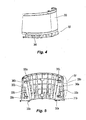
Figure 4 is an outside view of the fixed segment. -
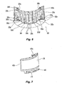
Figure 5 is an inside view of the fixed segment. -
Figure 6 is an inside view of the fixed segment, looking from below. -
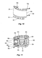
Figure 7 is an outside view of the first door. -
Figure 8 is an inside view of the first door. -
Figure 9 is an inside view of the first door, looking from below. -
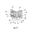
Figure 10 is an outside view of the second door. -
Figure 11 is an inside view of the second door. -
Figure 12 is an inside view of the second door, looking from below. -
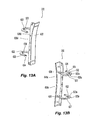
Figure 13A is an view of the third door showing its exterior surface. -
Figure 13B is an view of the third door showing its interior surface. -
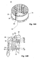
Figure 14A shows the tool with the third door opened inward. -
Figure 14B is a partial view of the tool showing the third door opened inward, as inFigure 14A . -
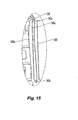
Figure 15 is a detailed view of a circumferentially facing panel of the fixed segment, showing the groove and the sealing member. -
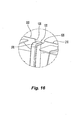
Figure 16 shows a notch formed at the top of a joint between the fixed segment and a door. -
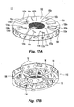
Figure 17A is a perspective view of the top side of the base. -
Figure 17B is a perspective view of the underside of the base. -
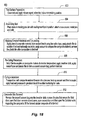
Figure 18 shows the principal steps in an exemplary process for making a tubular composite using the tool ofFigure 1 . -
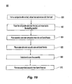
Figure 19 shows the principal steps for using the tool ofFigure 1 to assemble an acoustic inner barrel using the tubular composite. - The contents of aforementioned
U.S. published Patent Application No. 2007/0062022 are incorporated by reference to the extent necessary to understand the present invention. -
Figs. 1 and 2 show two perspective views of atool 100 in accordance with the present invention. As seen inFigs. 1-2 , the tool is in the "molding" state - i.e., thetool 100 is ready to have one or more layers of composite material applied to its axially extending tubular exterior surface to form a tubular composite member, such as an inner skin of an acoustic inner barrel for an aircraft gas turbine engine. In contrast,Fig. 3 shows thetool 100 in the "collapsed" state, in which a tubular composite member formed on the tool may be removed from the tool. - The
tool 100 comprises abase 110 on which is mounted atubular molding assembly 105. In one embodiment, the base has a diameter of approximately 3.4 meters while the height of the tool, including the base, is approximately 3.1 meters. - As best seen in
Figs. 17A and 17B , thebase 110 is circular in shape and comprises anupper surface 192 and askirt 194 extending downwardly therefrom. A set of fourwheels 196 is attached to the bottom of the base 110 to help roll the base along a floor or other surface on which thebase 110 rests. Thebase 110 is also provided with at least one pair of rectangulartubular members 198, each tubular member traversing the base 110 in a chord-like manner. Thetubular members 198 are configured and dimensioned to serve as forklift receiving structures suitable for receiving forklift prongs, to facilitate lifting and transporting thebase 110. - The
tubular molding assembly 105 comprises a fixedsegment 200, and threemovable segments base 110. In one embodiment,movable segments first door 210, asecond door 220 and athird door 230, respectively. As seen inFigs. 1 - 2 , the fixedsegment 200 rests on fixedsegment support 202 which comprises a fixedsegment support base 348; thefirst door 210 rests onfirst door support 212 which comprises a firstdoor support base 448; and thesecond door 220 rests onsecond door support 222 which comprises a seconddoor support base 548. - The
first door 210 is hingedly connected at one circumferential end to a first, opposing circumferential end of the fixedsegment 200. Similarly,second door 220 is hingedly connected at one circumferential end to a second, opposing circumferential end of the fixedsegment 200. Thethird door 230 is hingedly connected to thesecond door 220, as described further below. - During normal use, a
door Figs. 1 and 2 , and is considered to occupy a 'retracted position' whenever it is moved in an inward direction relative to its 'molding position', as seen inFig. 3 . In the present application, we refer to the entire tool as being in a 'molding position' when all of the doors are closed; we refer to the entire tool as being in a "collapsed position" when any one of the doors is opened; and we refer to the tool as being in an "non-molding position" when all of doors have been opened. - In one embodiment, the
base 110 is formed from steel while thetubular molding assembly 105 is formed from a different material. In general, thetubular molding assembly 105 is formed from a material which has a thermal properties that are similar to that the material to be formed on the tool, over a temperature range to which the assembly is exposed during normal use. In one embodiment, thetubular molding assembly 105 is formed from INVAR 36® or other material having a coefficient of thermal expansion that is similar to that of a graphite-epoxy composite part that is to be molded on the tool. Having similar thermal coefficients of expansion of thetubular molding assembly 105 and such a part eliminates different thermal expansion rates which otherwise would cause thermal loading between the part and the tool during heating and/or cooling, resulting in damage to the part. In one non-limiting example, the thermal coefficients of expansion of thetubular molding assembly 105 and the graphite-epoxy composite part formed thereon differ by less than 10% over the temperature range to which the assembly is exposed during normal use. Furthermore, a base formed from steel is less costly than a base formed from a material such as INVAR 36®. - The fixed
segment 200 and each of thedoors tool 100. Thethird door 230 fits between facing edges of thefirst door 210 and thesecond door 220. And as seen inFigs. 1-2 , the outer surface of thethird door 230 forms a portion of an outer contour of the tool, when the tool is in the molding position. Thethird door 230 is constructed and arranged to provide the exterior of thetool 100 with a smooth outer surface in the region between thefirst door 210 and thesecond door 220. One way to characterize the smoothness of the outer surface at the interface between thethird door 230 and either thefirst door 210 or thesecond door 220, is with reference to the maximum step difference along the abutting edges. Minimizing the step difference helps promote the aerodynamic properties of the completed part. In one embodiment, this step difference is less than about 0.05 cm. More preferably, however, the step difference is on the order of less than 0.005 cm. - The
third door 230 should be smaller than either the first orsecond doors third door 230 may be to break surface tension of a cured product by initiating separation between the cured product and the outer surface of the tool mandrel on which it is formed. Thus, the size of the third door may be dictated by the surface area required to break tension, and this may depend on the size of the tool. Thus, for example, thethird door 230 may subtend a smaller circumferential extent in a tool with a larger diameter, than in a tool with a smaller diameter. Furthermore, thethird door 230 must provide enough clearance to allow thesecond door 220 to move past the end of thefirst door 210, in view of the contours of the first and second doors. - In one embodiment, the fixed
segment 200 subtends between 160° and 180°, though more preferably is closer to 180°. In one preferred embodiment of thetool 100, the fixed segment 20 subtends just under 180°, thefirst door 210 andsecond door 220 each subtend approximately, 87°, and thethird door 230 subtends approximately 6°. Thus, in a tool having a diameter of 300 cm (3 meters) at a point midway between the tool's upper and lower rims, thethird door 230 has a medial circumferential extent of approximately 15 cm. In other embodiments, thethird door 230 subtends between 3° - 9° out of the full 360° extent of thetool 100. In still other embodiments, thethird door 230 has a circumferential extent no greater than one-quarter of a circumferential extent of the smaller of thefirst door 210 and thesecond doors 220. More preferably, though, thethird door 230 has a circumferential extent no greater than one-tenth of a circumferential extent of the smaller of thefirst door 210 and the second door. -
Figs. 4-6 show thefixed segment 200, its fixedsegment support 202, and its fixed segment support base 248 in further detail. The fixedsegment 200 has a firstcircumferential end 330a which is opposite a corresponding firstcircumferential end 430a of the first door 210 (SeeFig. 8 ) and a secondcircumferential end 330a which is opposite a corresponding circumferential end 530a of the second door 220 (seeFig. 11 ), when thetool 100 is in the molding position. The circumferential ends 330a, 330a of the fixedsegment 200 are each provided with acircumferentially facing panel circumferentially facing panels structure fixed segment 200 and each of thefirst door 210 and thesecond door 220. In one embodiment, each sealing structure is configured as a groove, as discussed further below with respect toFig. 15 . - As seen in
Figs. 4 and 5 , proximate its firstcircumferential end 330a, the fixedsegment 200 is provided with a pair of vertically spaced apart hingeplates arms circumferential end 430a of thefirst door 210. Similarly, proximate its secondcircumferential end 330a, the fixedsegment 200 is provided with a pair of vertically spaced apart hingeplates arms circumferential end 530b of thesecond door 220. -
Fig. 6 shows the details of the fixedsegment support 202 and the fixedsegment support base 348. The fixedsegment support base 348 has a lower surface to which are affixed a plurality of machinedpads 350a-e. The machinedpads 350a-e are mounted on corresponding mountingpads 150a-e formed on thetop surface 192 of the tool base 110 (seeFig. 17A ). In one embodiment, five suchmachined pads 350a-e are provided on the fixedsegment support base 348 and fivecorresponding mounting pads 150a-e are provided on thetool base 110. - Central
machined pad 350c is provided with a pair of radially spaced apart clearance holes through which threadedshoulder bolts 360c pass for mating with a pair of radially spaced tappedholes 160c formed oncentral mounting pad 150c provided on thetool base 110.Lateral machine pads shoulder bolts holes lateral mounting pads - First lateral machined
pad 350a is further provided with a first fixedpin 363a which mates with a slottedbushing 153a formed on the firstlateral mounting pad 150a. Second lateral machinedpad 350e is provided with a second fixed pin 363b which mates with around bushing 153e formed on the secondlateral mounting pad 150e. The slot of the slottedbushing 153a extends in a radial direction to facilitate mounting onto thebase 110 and accommodate thermal expansion of the fixedsegment 202 relative to thebase 110. -
Figs. 7-9 show thefirst door 210, itsfirst door support 212 and its firstdoor support base 448 in further detail. Thefirst door 210 has a firstcircumferential end 430a which is opposite the corresponding firstcircumferential end 330a of the fixedsegment 200, and a secondcircumferential end 430c which is opposite a corresponding firstcircumferential end 630c of thethird door 230, when thetool 100 is in the molding position. The circumferential ends 430a, 430c of thefirst door 210 are each provided with acircumferentially facing panel panel 438c is provided with a sealing structure of the sort described above. - As seen in
Figs. 7 and8 , proximate its firstcircumferential end 430c, thefirst door 210 is provided with a pair of vertically spaced apartcross-brace receiver pads Figs. 10 and 11 ). Proximate its secondcircumferential end 430a, thefirst door 210 is provided with a pair of vertically spaced apart hingearms plates segment 200, as described above. One ormore handles 425 is provided on an interior surface of thefirst door 210 to facilitate grabbing when thefirst door 210 is to either be pushed out or pulled inwardly, from inside thetool 100. -
Fig. 9 shows the details of thefirst door support 212 and the firstdoor support base 448. The firstdoor support base 448 has a lower surface to which are affixed a plurality offirst door pads 450a-c. Each of thefirst door pads spherical wheel assembly first door 210 is opened or closed, thewheel assemblies door wear plates top surface 192 of the tool base 110 (seeFig. 17A ). As seen inFig. 17A , the firstdoor wear plates first door 210 is operated. Thespherical wheel assemblies wear plates first door 210 along an arcuate path by simply pushing or pulling on one or more door handles. It is understood that thewear plates - As also seen in
Fig. 9 , thefirst door pad 450b is additionally provided with a pair of spaced apart first door stops, including a radially outerfirst door stop 472a and a radially innerfirst door stop 472b. The extent of travel of thefirst door 210 is limited, at least in part, by these first door stops 472a, 472b, when they abut correspondingfirst door abutments top surface 192 of the tool base 110 (seeFig. 17A ). -
Figs. 10-12 show thesecond door 220, itssecond door support 222 and its seconddoor support base 548 in further detail. Thesecond door 220 has a firstcircumferential end 530b which is opposite the corresponding secondcircumferential end 330b of the fixedsegment 200, and a secondcircumferential end 530d which is opposite a corresponding secondcircumferential end 630d of thethird door 230, when thetool 100 is in the molding position. The circumferential ends 530b, 530d of thesecond door 220 are each provided with acircumferentially facing panel panel 538d is provided with a sealing structure of the sort described above. - As seen in
Figs. 10 and 11 , proximate its firstcircumferential end 530b, thesecond door 220 is provided with a pair of vertically spaced apart hingearms plates segment 200. Proximate its secondcircumferential end 530d, thesecond door 220 is provided with a pair of vertically spaced apart thirddoor pivot attachments third door 230, as discussed below. - Also proximate its second
circumferential end 530d, thesecond door 220 is provided with a pair of vertically spaced apart cross-bracepivotal mounts tool 100 is in the molding position, the opposite free ends of the cross-braces 510u, 510n are connected to thecross-brace receiver pads first door 210 to enhance the structural rigidity of thetool 100 and to prevent accidental opening of thetool 100. Thus, the cross-braces 510u, 510n extend in a lateral direction, parallel to thetop surface 192 of thebase 110. One ormore handles 525 is provided on an interior surface of thesecond door 220 to facilitate grabbing when thesecond door 220 is to either be pushed out or pulled inwardly, from inside thetool 100. -
Fig. 12 shows the details of thesecond door support 222 and the seconddoor support base 548. The seconddoor support base 548 has a lower surface to which are affixed a plurality ofsecond door pads 550a-c. Each of thesecond door pads spherical wheel assembly second door 220 is opened or closed, thewheel assemblies door wear plates top surface 192 of the tool base 110 (seeFig. 17A ). As seen inFig. 17A , the seconddoor wear plates second door 220 is operated. However, since thesecond door 220 opens wider than the first door, the lengths of the seconddoor wear plates door wear plates spherical wheel assemblies door wear plates second door 220 along an arcuate path by simply pushing or pulling on one or more door handles 525. It is understood that thewear plates - Since the
first door 210, thesecond door 220 and thethird door 230 can all be manually operated, no external tooling is needed to move the doors between their open and closed positions. - As also seen in
Fig. 12 , thesecond door pad 550b is additionally provided with a pair of spaced apart second door stops, including a radially outersecond door stop 574a and a radially innersecond door stop 574b. The extent of travel of thesecond door 220 is limited, at least in part, by these second door stops 574a, 574b, when they abut correspondingsecond door abutments top surface 192 of the tool base 110 (seeFig. 17A ). -
Figs. 13A and 13B show thethird door 230. Thethird door 230 has anexterior surface 632 which conforms to the desired shape of a potion of the part to be made with thetool 100. Onecircumferential end 630d of thethird door 230 is provided with acircumferentially facing panel 638d. When thetool 100 is in the molding position, the third door's circumferentially facingpanel 638d opposes the second door's circumferentially facingpanel 538d. In contrast, the othercircumferential end 630c of thethird door 230 is provided with acircumferentially facing edge 648c which is narrower than a width of thecircumferentially facing panel 638d. When thetool 100 is in the molding position, the third door'scircumferentially facing edge 648c opposes the first door's circumferentially facingpanel 438c. - The third door is provided with a pair of vertically spaced apart "goose-neck" or
U-shaped hinges third door 230 on an inner surface thereof. The free ends 624 of the U-shaped hinges 620u, 620n are provided withpivot openings 626 for mounting on the aforementioned vertically spaced apart thirddoor pivot attachments hinge plate 528 of the second door 220 (seeFig. 14B ). - The
central arm 627 of eachU-shaped hinge hinge block 622 and a hingepin receiving bore 628. Eachhinge pinning block 622 cooperates with a correspondingsecond door block 522 mounted proximate the circumferentialsecond end 530d of thesecond door 220, as discussed below with respect toFig. 14B . Each hingepin receiving bore 628 is configured to receive ahinge pin 636. -
Fig. 14A shows thetool 100 with thefirst door 210 and thesecond door 220 still in the molding position, but with thethird door 230 ajar.Fig. 14B shows an enlarged view from the interior of thetool 100 as seen inFig. 14A , the view taken alongcross-sectional line 14B - 14B. As seen inFig. 14B , thethird door 230 opens towards the interior of thetool 100 with eachU-shaped hinge corresponding hinge plate 528. Eachhinge plate 528 carries asecond door block 522, a corresponding thirddoor pivot attachment - When the third door is closed, the hinge
pin receiving bore 628 is aligned with a hinge plate bore formed in thehinge plate 528, and thehinge pin 636 may be inserted into the aligned bores to prevent thehinge third door 230 from accidentally opening. Additionally, when thethird door 230 is closed, eachhinge block 622 is brought into juxtaposition with a correspondingsecond door block 522, andopenings respective blocks blocks openings third door 230 in the closed position. - The procedure for adjusting the
tool 100 from a first position (such as seen inFigs. 1-2 ) in which composite material may be applied on an outer surface of the tool to a second position (such as seen inFig. 3 ) in which the molded part may be removed after the curing process is given next. From inside the tool: (1) both cross-braces 510u, 510n rigidly connecting thefirst door 210 and thesecond door 220 are unbolted; (2) the third door is unpinned (i.e.,hinge pin 636 is removed from the alignedopenings second door 220 is unpinned and retracted; and (5) thefirst door 210 is unpinned. Then, from outside the tool: (6) thefirst door 210 is retracted; and (7) any part formed on thetool 100 may then be removed. - As seen in
Fig. 15 , an interface panel, such asinterface panel 338a is provided with a sealing structure in form of acircumferentially facing groove 340a Thegroove 340a extends substantially along the entire height of theinterface panel 338a and has radially outwardly extending upper andlower groove channels 342u, 342n. The groove 340A is configured and dimensioned to snugly receive an appropriately sized and shapedflexible sealing member 390. In one embodiment, the flexible sealing member comprises a tubular section of flexible material, such as rubber. The sealingstructure 340a and theflexible sealing member 390 together form a sealing arrangement. When the tool is in the molding portion, this sealing arrangement helps form a seal between adjacent segments. It is therefore understood that the interface between thefixed segment 200 and thefirst door 210 has such a sealing arrangement, as does the interface between thefixed segment 200 and thesecond door 210. A similar sealing arrangement is also provided at the interface between thefirst door 210 and thethird door 230, and at the interface between thesecond door 220 and thethird door 230. In one embodiment, as described above, the grooves are formed on both circumferentially facingpanels segment 200, on the first door's circumferentially facingpanel 438c that faces thethird door 230, and on the second door's circumferentially facingpanel 538d that faces thethird door 230. - As seen in
Figs. 1 and16 , when thedoors notches 120 are formed between thefixed segment 200 and thefirst door 210, and also between thefixed segment 200 and thesecond door 220. Eachnotch 120 is created whencutouts 126 formed at the top and bottom corners of the fixedsegment 200 and at the corresponding facing corners of thedoors notches 120 facilitate the use of vacuum bagging in the event the compressible seals fail. More particularly, the notches are regions where ends of polymer films for vacuum bagging meet to seal the composite material, prior to and during curing, in a manner known to those skilled in the art. Acover member 370 is provided to protect plastic bags during vacuum sealing from sharp edges at the interface between thefixed segment 200 and thefirst door 210 - In the foregoing discussion, one fixed segment and three movable segments in the form of three doors were employed, the smallest door being substantially smaller than either of the other two doors. It is also possible to form a tool with one fixed segment and two movable segments (doors), one door being larger than the other door. In such case, the larger of the two doors is hingedly connected at a first circumferential end to a first circumferential end of the fixed segment. A first circumferential end of the smaller of the two doors is then hingedly connected to the larger door's second circumferential end. In the completed tool, the second circumferential end of the smaller of the two doors meets the second circumferential end of the fixed segment to thereby form the 360 tool. Sealing arrangements including grooves and sealing members as described above may be provided at the three interfaces. In one such three-segment embodiment, the fixed portion may again subtend roughly 180°, the first (larger) hinged door may subtend about 144° - 164° and the second (smaller) hinged door (hinged to the may subtend the remainder of about 16° - 36° (or roughly one-quarter to one-tenth the size of the larger door). The non-right-cylindrical geometry of the tool may determine whether or not such a three-segment section is at all possible, and may also help determine the size for the smaller door.
- To form a composite tubular structure, the
tool 100 is adjusted to the molding position and composite material is applied in a pre-determined horizontal band between the upper and lower edges of the fixedsegment 200 and thedoors various segments - An upper bead of sealant and a lower bead of sealant may be circumferentially applied around the outer surface of the
tool 100 to adhere the plastic film to thetool 100. As is known to those skilled in the art, vacuum bag sealant tape (two-sided "chromate tape" with peel-off backing on both sides), such as model no. GS 213-3, available from General Sealants of Industry, CA may be suitable for use as sealant beads. - With the beads of sealant applied to secure the plastic film, a first portion of polymer film, such as a nylon film, may then be placed on the outer surface of the
tool 100. This first portion of film is a single piece that extends around the entire circumference of the tool and is overlapped in the circumferential direction by 2-3 centimeters or so, the overlapping ends secured by an axially extending piece of chromate tape. This first portion of nylon film is of sufficient height to contact the upper and lower beads. Preferably, the upper edge of the nylon film extends above the upper bead around the entire circumference of the tool, while the lower edge of the first portion of nylon film extends below the lower bead around the entire circumference of the tool. The first portion of the film also extends across eachnotch 120, and is secured to those portions of the beads that extend across each notch. In one embodiment, an IPPLON® KM 1300 nylon film, available from Airtech International, Inc. of Huntington Beach, CA may be used. - Second portions of nylon film, which are sized to cover each of the interface regions between the segments may optionally be applied on the inside surface of the
tool 100 and are secured to the first portion of nylon film via beads at the notches, in a known manner. As a result, the first film portion and the second film portion may sealingly join and engage each other. This serves as a backup in case the sealingmembers 390 fail. In this manner, a vacuum bag is formed, the vacuum bag creating a seal around the interface regions and the adjoining areas where the edges of thesegments - An exemplary use of the
tool 100 is presented next with reference toFig. 18 . This exemplary use illustrates one embodiment of aprocess 800 for making a composite inner skin of a 360° acoustic inner barrel for a nacelle inlet, using thetool 100. The process entails a number of phases:tool surface preparation 802;tool assembly 804; application ofcomposite material 806; preparation for curing 808; curing in anautoclave 810; and compositeinner skin removal 812. People skilled in the art are familiar with these processes, as evidenced by aforementionedU.S. Published Application No. 2007/0062022 . - First, the tool surface is prepared, in a known manner. The tool
surface preparation process 802 entails: interface areas. A first portion of polymer film is wrapped around the circumference of the tool such that it contacts and seals against the upper lower beads of sealant tape in the manner described above. Additionally, second portions of polymer film may optionally be applied to form a seal with a corresponding one of the tape beads that extend around each interface area on the inside surface of the tool, in the manner described above. In such case, the first portion of polymer film sealingly engages the second portions of polymer film at each notch pair; - (4) Compacting the plies against the tool surface by applying a vacuum to the first vacuum bag. A metal fitting is installed on the vacuum bag, such as by taping with sealant tape, a first end of a hose is connected to the fitting and a second end of the hose is connected to a vacuum pump. The suction exerted by the vacuum pump is sufficient to compact the composite material. Therefore, no mechanical pressure other than that provided by the plastic film of the vacuum bag pressing against the composite material is needed to perform the compaction; and
- (5) After compacting for 20 - 30 minutes, releasing the vacuum and removing the first vacuum bag and sealant tape. At this point, the composite materials have been compacted.
- Next, in a
pre-curing phase 808, the tool with the compacted fabric thereon is prepared for the autoclave. Preparation for curing entails: - (1) Installing thermocouples on the tool and on the composite material to monitor the curing process;
- (2) Applying breather cloth over the compacted composite material. In a preferred embodiment, the breather cloth is a nylon mat, such as Model No. Ultraweave 1332, available from Airtech International of Huntington Beach, CA;
- (3) Applying a fresh layer of two-sided vacuum bag sealant tape and polymer film to form a second vacuum bag in the same manner as described above with respect to the first vacuum sealant bag. The second vacuum bag is formed over the breather cloth which itself covers the compacted composite material; and
- (4) Applying vacuum to the second vacuum bag and performing a leak test by applying a vacuum and gauging the pressure to determine whether a leak is
- (1) Adjusting the tool into a non-molding position (if not already done);
- (2) Cleaning the tool with a solvent; and
- (3) Applying a release agent, such as FREEKOTE™ to the outer surfaces of the segments.
- Next, the tool is assembled and configured for use. As seen in
Fig. 18 , thetool assembly process 804 entails: - (1) Closing the
first door 210 and installing pins to secure thefirst door 210 relative to thebase 110. - (2) Closing the
second door 210 and installing pins to secure thesecond door 220 relative to thebase 110. - (3) Attaching the cross-braces 510u, 510n on the
second door 220 to thecross-brace pads - (4) Closing the
third door 230 and installing thehinge pin 636. - After the
tool 100 is assembled, composite material is applied to the external surface of the tool in a conventional lay-up process and compacted by vacuum. The composite material application andcompaction process 806 entails: - (1) Laying on plies of composite material in the form of graphite-epoxy prepreg fabric on the tool's outer surface. Segments of the fabric about 1.1 meters in height, each circumferentially subtending about 60°, are placed on the outer surface of the tool, adjacent segments overlapping one another by about 2-3 cm. No tape or adhesives are used to secure overlapping fabric segments since they may contaminate the final composite structure. About 3 or 4 such plies are layed on at a time;
- (2) Applying two-sided vacuum bag sealant tape around the top and bottom peripheries of the outer surface of the tool and along the interface areas on the inner surface of the tool to form the sealant bead. The two-sided tape is applied to the outer surface of the tool, and not to the surface of the composite material. On the outer surface of the tool, a gap of about 13 to 18 cm is left between the circumferentially extending upper and lower edges of the composite material and the circumferentially extending upper and lower sealant beads;
- (3) Applying polymer film to form a first vacuum bag around the fabric and along the present.
- After this, the tool, with the composite materials applied thereon, along with the breather cloth, is cured in an autoclave. The
autoclave curing phase 810 entails: - (1) Moving the
tool 100 into the autoclave and hooking up vacuum and thermocouple connections; - (2) Closing the autoclave door and running through a predetermined heat and pressure cycle to cure the composite. The vacuum bag remains under vacuum until the autoclave pressure is high enough above atmospheric pressure, at which point the vacuum bag is vented to atmospheric pressure. The bag is monitored to ensure that it does not go to positive pressure during the cure cycle, positive pressure indicating a leak; and
- (3) Opening the autoclave and removing the
tool 100 with the tubular composite formed thereon. - After curing in the autoclave, the composite inner skin is removed from the
tool 100. The composite innerskin removal process 812 entails: - (1) Removing the vacuum bag and the breather cloth;
- (2) Removing the hinge pins 636 and opening the
third door 230; - (3) Detaching the cross-braces 510u, 510n between the first and second doors;
- (4) Removing pins and opening the
second door 220 from the inside; - (5) Removing pins and opening the
first door 210 from the outside; - (6) Lifting the composite inner skin of the tool from the
tool 100. - It is understood that there may be other steps in each of the above-described phases. It is also understood that the some of the steps in one or more of the above-described phases may be taken out of the sequence presented above.
- Once the composite inner skin is formed, it generally is subject to additional processing, such as perforation for acoustic attenuation. This, however, is done by a separate process using separate tools. The acoustic core and the outer skin are also formed using separate processes and separate tools.
- A bond panel for an acoustic inner barrel may be formed by bonding together the composite inner skin, the acoustic core and the outer skin, with help of the
tool 100.Fig. 19 shows aprocess 900 to accomplish this. First, instep 902, the composite inner skin is placed over a slightly collapsedtool 100 and the tool is then adjusted to the molding position such that the outer surface of the tool supports the inner skin. As indicated bypreliminary step 899, the composite inner skin may first have been molded on the tool, thedoors tool 100, and only then subsequently repositioned on thetool 100. Next, instep 904, the acoustic core (e.g., honeycomb core typically used in engine nacelles) is positioned over the composite inner skin and bonded thereto. After this, instep 906, the outer skin is positioned over the acoustic core and bonded thereto. Instep 908, the resulting assembly is then cured in an autoclave. Finally, instep 910, the bonded inner skin/core/outer skin assembly is removed from the tool. People skilled in the art understand how to bond adjacent layers for such an acoustic liner. - While the present invention has been described herein above in connection with a plurality of aspects and embodiments, it is understood that these aspects and embodiments were presented by way of example with no intention of limiting the invention. Accordingly, the present invention should not be limited to any specific embodiment or aspect, but rather construed in breadth and broad scope in accordance with the recitation of the claims appended hereto.
Claims (14)
- A 360° tool for making a 360° composite tubular structure, the tool being adjustable between a molding position and a non-molding position, the tool comprising:a base;at least one fixed segment that is fixed relative to the base, the at least one fixed segment having a first circumferential end and a second circumferential end;a first door having a first circumferential end hingedly connected to the first circumferential end of the at least one fixed segment;a second door hingedly connected to the first door and configured to fit between the first door and the second circumferential end of the fixed segment to thereby complete the 360° circumferential extent of the tool; anda sealing member between the at least one fixed segment and each of the first and second doors and also between the first door and the second door; wherein:the second door has a circumferential extent no greater than one-quarter of a circumferential extent of the first door.
- The 360° tool according to claim 1, wherein:the first door subtends about 144° - 164°; andthe second door subtends about 16° - 36°.
- The 360° tool according to claim 1, wherein:the fixed segment is provided with two grooves formed on circumferentially facing portions at each end thereof;the first door is provided with a groove formed on a circumferentially facing portion thereof facing the second door; andeach groove receives a corresponding sealing member.
- The 360° tool according to claim 1, wherein:the first door is provided with a plurality of wheels to facilitate opening and closing; andan upper surface of the base is provided with a plurality of replaceable wear plates on which said plurality of wheels travel, during articulation of the first door.
- The 360° tool according to claim 1, comprising:pairs of cutouts formed in the upper facing corners of the first door and the fixed segment; andeach pair of cutouts cooperates to form a notch, when the tool is in the molding position.
- The 360° tool according to claim 1, wherein:the base is formed of steel and has a first thermal coefficient of expansion; andthe fixed segment and the first and second doors have a second thermal coefficient of expansion which is similar to a thermal coefficient of expansion of a graphite-epoxy composite.
- A method for molding a tubular composite inner skin for an acoustic inner barrel, the method comprising:providing a 360° tool in accordance with claim 1;adjusting the doors until the tool is in the molding position;applying composite material on the outer surface of the tool;curing the composite material to form an inner skin; andremoving the inner skin from the outer surface.
- The method according to claim 7, further comprising:moving the tool into an autoclave with the composite material still on the outer surface, prior to curing the composite material.
- The method according to claim 7, further comprising, prior to curing:placing sealant proximate upper and lower edges of the fixed segment and the doors, said sealant extending across notches formed between adjacent segments; andplacing a first portion of film over the composite material, said first portion of film contacting said sealant.
- The method according to claim 9, further comprising, prior to curing:placing sealant on an inner surface the tool at interfaces between the fixed segment and the first and second doors; andplacing a second portion of film over said interfaces, said second portion of film contacting said sealant.
- The method according to claim 10, further comprising, prior to curing:placing sealant proximate upper and lower edges of the fixed segment and the doors, said sealant extending across notches formed between the fixed segment and the first door;placing a first portion of film over the composite material, said first portion of film contacting said sealant; andsealingly joining together end sections of the first and second portions of film at said notches.
- The method according to claim 11, further comprising sealingly joining together end sections of the first and second portions of film in notches formed between the fixed segment and the first door.
- A method for making a bond panel for an acoustic inner barrel, the method comprising:providing a 360° tool in accordance with claim 1;placing a tubular composite inner skin over the tool while the first door is in an inwardly articulated position;adjusting the tool to the molding position such that the outer surface of the tool supports the inner skin;positioning an acoustic core over the inner skin and bonding the acoustic core thereto;positioning an outer skin over the acoustic core and bonding the outer skin thereto;curing the resulting assembly; andremoving the bonded inner skin/core/outer skin composite structure from the tool.
- The method according to claim 13, comprising, prior to positioning said acoustic core over the inner skin:molding the inner skin on the tool;removing the inner skin from the tool; and
subsequently re-positioning the inner skin on the tool.
Applications Claiming Priority (2)
| Application Number | Priority Date | Filing Date | Title |
|---|---|---|---|
| US12/052,968 US7640961B2 (en) | 2008-03-21 | 2008-03-21 | Apparatus and method for making a tubular composite barrel |
| EP09003566A EP2103404B1 (en) | 2008-03-21 | 2009-03-11 | Apparatus and method for making a tubular composite barrel |
Related Parent Applications (1)
| Application Number | Title | Priority Date | Filing Date |
|---|---|---|---|
| EP09003566.8 Division | 2009-03-11 |
Publications (2)
| Publication Number | Publication Date |
|---|---|
| EP2450171A1 true EP2450171A1 (en) | 2012-05-09 |
| EP2450171B1 EP2450171B1 (en) | 2013-05-08 |
Family
ID=40848219
Family Applications (2)
| Application Number | Title | Priority Date | Filing Date |
|---|---|---|---|
| EP12000610.1A Not-in-force EP2450171B1 (en) | 2008-03-21 | 2009-03-11 | Apparatus and method for making a tubular composite barrel |
| EP09003566A Not-in-force EP2103404B1 (en) | 2008-03-21 | 2009-03-11 | Apparatus and method for making a tubular composite barrel |
Family Applications After (1)
| Application Number | Title | Priority Date | Filing Date |
|---|---|---|---|
| EP09003566A Not-in-force EP2103404B1 (en) | 2008-03-21 | 2009-03-11 | Apparatus and method for making a tubular composite barrel |
Country Status (2)
| Country | Link |
|---|---|
| US (2) | US7640961B2 (en) |
| EP (2) | EP2450171B1 (en) |
Families Citing this family (18)
| Publication number | Priority date | Publication date | Assignee | Title |
|---|---|---|---|---|
| US7707708B2 (en) * | 2005-09-21 | 2010-05-04 | Rohr, Inc. | Apparatus for making a tubular composite structure |
| GB2449907B (en) * | 2007-06-07 | 2010-02-10 | Gkn Aerospace Services Ltd | Composite flange and method of making such flange |
| US8025499B2 (en) | 2008-11-03 | 2011-09-27 | Rohr, Inc. | Multi-segment tool and method for composite formation |
| US8661644B2 (en) | 2010-10-06 | 2014-03-04 | The Boeing Company | Method and device for forming joints in composite structures |
| US8784596B2 (en) | 2010-11-19 | 2014-07-22 | The Boeing Company | Method for making and joining composite sandwich shell edge joint |
| US8875931B2 (en) | 2010-11-19 | 2014-11-04 | The Boeing Company | Composite sandwich shell edge joint |
| RU2482028C1 (en) * | 2011-12-21 | 2013-05-20 | Открытое акционерное общество "Национальный институт авиационных технологий" (ОАО НИАТ) | Berth for assembly of aircraft engine air intake |
| FR2991628A1 (en) * | 2012-06-12 | 2013-12-13 | Aircelle Sa | TOOL ASSEMBLY FOR MANUFACTURING COMPOSITE WORKPIECE AND METHOD FOR MANUFACTURING COMPOUND PIECE. |
| DE202013103475U1 (en) * | 2013-08-02 | 2014-11-04 | Krones Aktiengesellschaft | Vacuum cylinder for a labeling device and labeling device with a vacuum cylinder |
| US10094242B2 (en) * | 2014-02-25 | 2018-10-09 | United Technologies Corporation | Repair or remanufacture of liner panels for a gas turbine engine |
| US10137607B2 (en) | 2014-10-01 | 2018-11-27 | The Boeing Company | Methods and apparatus for curing composite nacelle structure |
| US11407185B2 (en) * | 2017-12-18 | 2022-08-09 | The Boeing Company | Layup tools that facilitate transfer of laminates to cure tools |
| GB2571173B (en) * | 2017-12-18 | 2022-09-07 | Boeing Co | Layup tools that facilitate transfer of laminates to cure tools |
| RU183441U1 (en) * | 2017-12-29 | 2018-09-24 | Акционерное общество "НПО Энергомаш имени академика В.П. Глушко" | Stapel for assembling a three-dimensional design of a frame of a liquid rocket engine |
| GB2575295B (en) * | 2018-07-04 | 2022-06-15 | Rolls Royce Plc | An Alignment Tool |
| FR3084445B1 (en) * | 2018-07-25 | 2021-01-22 | Safran Aircraft Engines | MANUFACTURE OF A COMBUSTION CHAMBER IN COMPOSITE MATERIAL |
| IT201900004761A1 (en) | 2019-03-29 | 2020-09-29 | Leonardo Spa | Manufacturing process of a sound-absorbing panel with a sandwich structure to reduce the sound impact of an aircraft engine |
| CN112045906B (en) * | 2020-08-27 | 2022-03-25 | 冀州中意复合材料股份有限公司 | Large-scale compound flue mould that opens and shuts |
Citations (2)
| Publication number | Priority date | Publication date | Assignee | Title |
|---|---|---|---|---|
| EP1375111A2 (en) * | 2002-06-27 | 2004-01-02 | Airbus France | Segmented mould, particularly for the manufacturing of an air intake without connecting link |
| US20070062022A1 (en) | 2005-09-21 | 2007-03-22 | Rohr, Inc. | Method and apparatus for making a tubular composite structure |
Family Cites Families (27)
| Publication number | Priority date | Publication date | Assignee | Title |
|---|---|---|---|---|
| US1835986A (en) | 1927-10-12 | 1931-12-08 | Nat Rubber Machinery Co | Collapsible tire building form |
| US2586300A (en) * | 1947-08-07 | 1952-02-19 | John F Campbell | Collapsible v-belt mold |
| DE1262570B (en) | 1964-06-18 | 1968-03-07 | Mueller Ernst Kg | Hollow mandrel for the production of tubes or containers of any length made from helically wound plastic strips |
| DE1504597B2 (en) | 1965-11-06 | 1971-04-01 | Muller geb Schneider, Hedwig Ida, 5905 Freudenberg | COLLAR FOR THE MANUFACTURING OF PIPES OR CONTAINERS OF ANY LENGTH FROM SCREW-SHAPED PLASTIC STRIPS |
| US3768954A (en) * | 1969-06-03 | 1973-10-30 | R Marsh | Device for forming and handling concrete pipe |
| DE2259690A1 (en) | 1972-12-06 | 1974-06-12 | Bautenberg Gmbh | HOLLOW WINDING mandrel |
| DE2352373A1 (en) | 1973-10-18 | 1975-04-24 | Hermann Sarres | Wrapping mandrel for reinforced resin tubes - has expanding wedge for slot in glass fibre reinforced resin cylinder |
| GB1522558A (en) | 1976-04-05 | 1978-08-23 | Rolls Royce | Duct linings |
| DE2652862C2 (en) * | 1976-11-20 | 1979-01-04 | Basf Ag, 6700 Ludwigshafen | Mold core for the production of hollow bodies made of fiber-reinforced synthetic resin |
| US4288277A (en) | 1979-07-17 | 1981-09-08 | Lembit Siilats | Molding system with retracting mold |
| US4278490A (en) | 1979-12-21 | 1981-07-14 | Owens-Corning Fiberglas Corporation | Sleeve for changing diameter of collapsible mandrel |
| US4436574A (en) | 1982-12-13 | 1984-03-13 | Eagle-Picher Industries, Inc. | Radial mandrel |
| US4462787A (en) * | 1983-02-01 | 1984-07-31 | Bogardus Jr Carl R | Cantilevered mandrel assembly |
| EP0154038B1 (en) | 1984-02-08 | 1989-03-15 | Georg Prinzing GmbH & Co. KG Betonformen- und Maschinenfabrik | Moulding core with adjustable parts |
| IT1177395B (en) | 1984-12-12 | 1987-08-26 | Dino Piccoli | EQUIPMENT FOR THE DISCONTINUOUS PRODUCTION OF TUBULAR STRUCTURES |
| ATE47087T1 (en) * | 1986-08-23 | 1989-10-15 | Vv System Ag | EXPANDABLE RING FOR SEALING A SLEEVE ON THE BEAD OF A TIRE TO BE REPLACED. |
| US5022845A (en) * | 1989-04-25 | 1991-06-11 | Hercules Incorporated | Segmented mandrel for forming composite articles |
| AU9108391A (en) | 1991-02-19 | 1992-09-15 | John W. Boyd | Method and apparatus for producing a filament wound tank shell |
| US5228374A (en) * | 1991-08-09 | 1993-07-20 | Santeramo Sr Joseph J | Table saw fence assembly |
| US5266137A (en) | 1992-11-10 | 1993-11-30 | Hollingsworth Ritch D | Rigid segmented mandrel with inflatable support |
| DE4340951A1 (en) | 1992-12-04 | 1994-06-09 | Grumman Aerospace Corp | One-piece engine inlet sound tube |
| FR2767560B1 (en) | 1997-08-19 | 1999-11-12 | Aerospatiale | NOISE REDUCTION ASSEMBLY FOR AN AIRCRAFT TURBOREACTOR |
| US6458309B1 (en) | 1998-06-01 | 2002-10-01 | Rohr, Inc. | Method for fabricating an advanced composite aerostructure article having an integral co-cured fly away hollow mandrel |
| DE10010917A1 (en) * | 2000-03-06 | 2001-09-13 | Baumgaertner Maschf Gmbh | Mold mantle for casting concrete pipes is in sections to open and close the mantle with locks operated by a rod with settings to allow for relative movement during casting |
| FR2821788B1 (en) | 2001-03-09 | 2004-04-02 | Eads Airbus Sa | METHOD FOR MANUFACTURING A PANEL WITH A SOUND ACOUSTIC LAYER LAYER AND ACOUSTIC PANEL THUS OBTAINED |
| CN1972792B (en) * | 2004-06-21 | 2011-04-06 | 有限会社尽田产业 | Mold, injection molding device, and injection molding method |
| US7571527B2 (en) | 2005-03-29 | 2009-08-11 | The Boeing Company | Mandrel for fabrication of a monolithic composite nacelle panel |
-
2008
- 2008-03-21 US US12/052,968 patent/US7640961B2/en not_active Expired - Fee Related
-
2009
- 2009-03-11 EP EP12000610.1A patent/EP2450171B1/en not_active Not-in-force
- 2009-03-11 EP EP09003566A patent/EP2103404B1/en not_active Not-in-force
- 2009-11-19 US US12/622,138 patent/US8012286B2/en not_active Expired - Fee Related
Patent Citations (4)
| Publication number | Priority date | Publication date | Assignee | Title |
|---|---|---|---|---|
| EP1375111A2 (en) * | 2002-06-27 | 2004-01-02 | Airbus France | Segmented mould, particularly for the manufacturing of an air intake without connecting link |
| US7125237B2 (en) | 2002-06-27 | 2006-10-24 | Airbus France | Tooling for molding with keys particularly for the production of air intakes without clips |
| US20070062022A1 (en) | 2005-09-21 | 2007-03-22 | Rohr, Inc. | Method and apparatus for making a tubular composite structure |
| EP1767325A2 (en) * | 2005-09-21 | 2007-03-28 | Rohr, Inc. | Method and apparatus for making a tubular composite structure |
Also Published As
| Publication number | Publication date |
|---|---|
| US20100059185A1 (en) | 2010-03-11 |
| EP2103404A3 (en) | 2011-03-02 |
| US8012286B2 (en) | 2011-09-06 |
| EP2450171B1 (en) | 2013-05-08 |
| US20090236779A1 (en) | 2009-09-24 |
| US7640961B2 (en) | 2010-01-05 |
| EP2103404B1 (en) | 2012-06-06 |
| EP2103404A2 (en) | 2009-09-23 |
Similar Documents
| Publication | Publication Date | Title |
|---|---|---|
| EP2103404B1 (en) | Apparatus and method for making a tubular composite barrel | |
| US7861394B2 (en) | Method for making a tubular composite structure | |
| US7935289B2 (en) | Method of making composite panels for a fuselage | |
| US8303758B2 (en) | Methods for manufacturing composite sections for aircraft fuselages and other structures | |
| US9962917B2 (en) | Method of manufacturing single piece fuselage barrels in composite material | |
| KR102027013B1 (en) | Method and apparatus for producing contoured composite structures and structures produced thereby | |
| US11565460B2 (en) | Systems and methods for in situ manufacturing of minimally tooled stringers | |
| JP2021035760A (en) | System and method for manufacturing composite assembly | |
| CA2753735C (en) | Method and apparatus for manufacturing composite parts | |
| EP4011606B1 (en) | Caul plate system for aircraft fabrication | |
| EP4074497A1 (en) | Cauls having integrated edge seals and sealing method |
Legal Events
| Date | Code | Title | Description |
|---|---|---|---|
| PUAI | Public reference made under article 153(3) epc to a published international application that has entered the european phase |
Free format text: ORIGINAL CODE: 0009012 |
|
| 17P | Request for examination filed |
Effective date: 20120131 |
|
| AC | Divisional application: reference to earlier application |
Ref document number: 2103404 Country of ref document: EP Kind code of ref document: P |
|
| AK | Designated contracting states |
Kind code of ref document: A1 Designated state(s): AT BE BG CH CY CZ DE DK EE ES FI FR GB GR HR HU IE IS IT LI LT LU LV MC MK MT NL NO PL PT RO SE SI SK TR |
|
| RIC1 | Information provided on ipc code assigned before grant |
Ipc: B29C 33/48 20060101AFI20121001BHEP Ipc: B29C 70/44 20060101ALI20121001BHEP |
|
| GRAP | Despatch of communication of intention to grant a patent |
Free format text: ORIGINAL CODE: EPIDOSNIGR1 |
|
| GRAS | Grant fee paid |
Free format text: ORIGINAL CODE: EPIDOSNIGR3 |
|
| GRAA | (expected) grant |
Free format text: ORIGINAL CODE: 0009210 |
|
| AC | Divisional application: reference to earlier application |
Ref document number: 2103404 Country of ref document: EP Kind code of ref document: P |
|
| AK | Designated contracting states |
Kind code of ref document: B1 Designated state(s): AT BE BG CH CY CZ DE DK EE ES FI FR GB GR HR HU IE IS IT LI LT LU LV MC MK MT NL NO PL PT RO SE SI SK TR |
|
| REG | Reference to a national code |
Ref country code: GB Ref legal event code: FG4D |
|
| REG | Reference to a national code |
Ref country code: AT Ref legal event code: REF Ref document number: 610850 Country of ref document: AT Kind code of ref document: T Effective date: 20130515 Ref country code: CH Ref legal event code: EP |
|
| REG | Reference to a national code |
Ref country code: IE Ref legal event code: FG4D |
|
| REG | Reference to a national code |
Ref country code: DE Ref legal event code: R096 Ref document number: 602009015644 Country of ref document: DE Effective date: 20130704 |
|
| REG | Reference to a national code |
Ref country code: AT Ref legal event code: MK05 Ref document number: 610850 Country of ref document: AT Kind code of ref document: T Effective date: 20130508 |
|
| REG | Reference to a national code |
Ref country code: LT Ref legal event code: MG4D |
|
| REG | Reference to a national code |
Ref country code: NL Ref legal event code: VDEP Effective date: 20130508 |
|
| PG25 | Lapsed in a contracting state [announced via postgrant information from national office to epo] |
Ref country code: IS Free format text: LAPSE BECAUSE OF FAILURE TO SUBMIT A TRANSLATION OF THE DESCRIPTION OR TO PAY THE FEE WITHIN THE PRESCRIBED TIME-LIMIT Effective date: 20130908 Ref country code: GR Free format text: LAPSE BECAUSE OF FAILURE TO SUBMIT A TRANSLATION OF THE DESCRIPTION OR TO PAY THE FEE WITHIN THE PRESCRIBED TIME-LIMIT Effective date: 20130809 Ref country code: PT Free format text: LAPSE BECAUSE OF FAILURE TO SUBMIT A TRANSLATION OF THE DESCRIPTION OR TO PAY THE FEE WITHIN THE PRESCRIBED TIME-LIMIT Effective date: 20130909 Ref country code: SI Free format text: LAPSE BECAUSE OF FAILURE TO SUBMIT A TRANSLATION OF THE DESCRIPTION OR TO PAY THE FEE WITHIN THE PRESCRIBED TIME-LIMIT Effective date: 20130508 Ref country code: AT Free format text: LAPSE BECAUSE OF FAILURE TO SUBMIT A TRANSLATION OF THE DESCRIPTION OR TO PAY THE FEE WITHIN THE PRESCRIBED TIME-LIMIT Effective date: 20130508 Ref country code: LT Free format text: LAPSE BECAUSE OF FAILURE TO SUBMIT A TRANSLATION OF THE DESCRIPTION OR TO PAY THE FEE WITHIN THE PRESCRIBED TIME-LIMIT Effective date: 20130508 Ref country code: ES Free format text: LAPSE BECAUSE OF FAILURE TO SUBMIT A TRANSLATION OF THE DESCRIPTION OR TO PAY THE FEE WITHIN THE PRESCRIBED TIME-LIMIT Effective date: 20130819 Ref country code: FI Free format text: LAPSE BECAUSE OF FAILURE TO SUBMIT A TRANSLATION OF THE DESCRIPTION OR TO PAY THE FEE WITHIN THE PRESCRIBED TIME-LIMIT Effective date: 20130508 Ref country code: NO Free format text: LAPSE BECAUSE OF FAILURE TO SUBMIT A TRANSLATION OF THE DESCRIPTION OR TO PAY THE FEE WITHIN THE PRESCRIBED TIME-LIMIT Effective date: 20130808 Ref country code: SE Free format text: LAPSE BECAUSE OF FAILURE TO SUBMIT A TRANSLATION OF THE DESCRIPTION OR TO PAY THE FEE WITHIN THE PRESCRIBED TIME-LIMIT Effective date: 20130508 |
|
| PG25 | Lapsed in a contracting state [announced via postgrant information from national office to epo] |
Ref country code: HR Free format text: LAPSE BECAUSE OF FAILURE TO SUBMIT A TRANSLATION OF THE DESCRIPTION OR TO PAY THE FEE WITHIN THE PRESCRIBED TIME-LIMIT Effective date: 20130508 Ref country code: PL Free format text: LAPSE BECAUSE OF FAILURE TO SUBMIT A TRANSLATION OF THE DESCRIPTION OR TO PAY THE FEE WITHIN THE PRESCRIBED TIME-LIMIT Effective date: 20130508 Ref country code: BG Free format text: LAPSE BECAUSE OF FAILURE TO SUBMIT A TRANSLATION OF THE DESCRIPTION OR TO PAY THE FEE WITHIN THE PRESCRIBED TIME-LIMIT Effective date: 20130808 Ref country code: CY Free format text: LAPSE BECAUSE OF FAILURE TO SUBMIT A TRANSLATION OF THE DESCRIPTION OR TO PAY THE FEE WITHIN THE PRESCRIBED TIME-LIMIT Effective date: 20130508 |
|
| PG25 | Lapsed in a contracting state [announced via postgrant information from national office to epo] |
Ref country code: LV Free format text: LAPSE BECAUSE OF FAILURE TO SUBMIT A TRANSLATION OF THE DESCRIPTION OR TO PAY THE FEE WITHIN THE PRESCRIBED TIME-LIMIT Effective date: 20130508 |
|
| PG25 | Lapsed in a contracting state [announced via postgrant information from national office to epo] |
Ref country code: DK Free format text: LAPSE BECAUSE OF FAILURE TO SUBMIT A TRANSLATION OF THE DESCRIPTION OR TO PAY THE FEE WITHIN THE PRESCRIBED TIME-LIMIT Effective date: 20130508 Ref country code: BE Free format text: LAPSE BECAUSE OF FAILURE TO SUBMIT A TRANSLATION OF THE DESCRIPTION OR TO PAY THE FEE WITHIN THE PRESCRIBED TIME-LIMIT Effective date: 20130508 Ref country code: SK Free format text: LAPSE BECAUSE OF FAILURE TO SUBMIT A TRANSLATION OF THE DESCRIPTION OR TO PAY THE FEE WITHIN THE PRESCRIBED TIME-LIMIT Effective date: 20130508 Ref country code: CZ Free format text: LAPSE BECAUSE OF FAILURE TO SUBMIT A TRANSLATION OF THE DESCRIPTION OR TO PAY THE FEE WITHIN THE PRESCRIBED TIME-LIMIT Effective date: 20130508 Ref country code: EE Free format text: LAPSE BECAUSE OF FAILURE TO SUBMIT A TRANSLATION OF THE DESCRIPTION OR TO PAY THE FEE WITHIN THE PRESCRIBED TIME-LIMIT Effective date: 20130508 |
|
| PG25 | Lapsed in a contracting state [announced via postgrant information from national office to epo] |
Ref country code: RO Free format text: LAPSE BECAUSE OF FAILURE TO SUBMIT A TRANSLATION OF THE DESCRIPTION OR TO PAY THE FEE WITHIN THE PRESCRIBED TIME-LIMIT Effective date: 20130508 Ref country code: IT Free format text: LAPSE BECAUSE OF FAILURE TO SUBMIT A TRANSLATION OF THE DESCRIPTION OR TO PAY THE FEE WITHIN THE PRESCRIBED TIME-LIMIT Effective date: 20130508 Ref country code: NL Free format text: LAPSE BECAUSE OF FAILURE TO SUBMIT A TRANSLATION OF THE DESCRIPTION OR TO PAY THE FEE WITHIN THE PRESCRIBED TIME-LIMIT Effective date: 20130508 |
|
| PLBE | No opposition filed within time limit |
Free format text: ORIGINAL CODE: 0009261 |
|
| STAA | Information on the status of an ep patent application or granted ep patent |
Free format text: STATUS: NO OPPOSITION FILED WITHIN TIME LIMIT |
|
| 26N | No opposition filed |
Effective date: 20140211 |
|
| REG | Reference to a national code |
Ref country code: DE Ref legal event code: R097 Ref document number: 602009015644 Country of ref document: DE Effective date: 20140211 |
|
| PG25 | Lapsed in a contracting state [announced via postgrant information from national office to epo] |
Ref country code: LU Free format text: LAPSE BECAUSE OF FAILURE TO SUBMIT A TRANSLATION OF THE DESCRIPTION OR TO PAY THE FEE WITHIN THE PRESCRIBED TIME-LIMIT Effective date: 20140311 |
|
| REG | Reference to a national code |
Ref country code: CH Ref legal event code: PL |
|
| REG | Reference to a national code |
Ref country code: IE Ref legal event code: MM4A |
|
| PG25 | Lapsed in a contracting state [announced via postgrant information from national office to epo] |
Ref country code: CH Free format text: LAPSE BECAUSE OF NON-PAYMENT OF DUE FEES Effective date: 20140331 Ref country code: LI Free format text: LAPSE BECAUSE OF NON-PAYMENT OF DUE FEES Effective date: 20140331 Ref country code: IE Free format text: LAPSE BECAUSE OF NON-PAYMENT OF DUE FEES Effective date: 20140311 |
|
| REG | Reference to a national code |
Ref country code: FR Ref legal event code: PLFP Year of fee payment: 8 |
|
| PG25 | Lapsed in a contracting state [announced via postgrant information from national office to epo] |
Ref country code: MT Free format text: LAPSE BECAUSE OF FAILURE TO SUBMIT A TRANSLATION OF THE DESCRIPTION OR TO PAY THE FEE WITHIN THE PRESCRIBED TIME-LIMIT Effective date: 20130508 |
|
| PG25 | Lapsed in a contracting state [announced via postgrant information from national office to epo] |
Ref country code: MC Free format text: LAPSE BECAUSE OF FAILURE TO SUBMIT A TRANSLATION OF THE DESCRIPTION OR TO PAY THE FEE WITHIN THE PRESCRIBED TIME-LIMIT Effective date: 20130508 |
|
| PG25 | Lapsed in a contracting state [announced via postgrant information from national office to epo] |
Ref country code: HU Free format text: LAPSE BECAUSE OF FAILURE TO SUBMIT A TRANSLATION OF THE DESCRIPTION OR TO PAY THE FEE WITHIN THE PRESCRIBED TIME-LIMIT; INVALID AB INITIO Effective date: 20090311 Ref country code: TR Free format text: LAPSE BECAUSE OF FAILURE TO SUBMIT A TRANSLATION OF THE DESCRIPTION OR TO PAY THE FEE WITHIN THE PRESCRIBED TIME-LIMIT Effective date: 20130508 |
|
| REG | Reference to a national code |
Ref country code: FR Ref legal event code: PLFP Year of fee payment: 9 |
|
| REG | Reference to a national code |
Ref country code: FR Ref legal event code: PLFP Year of fee payment: 10 |
|
| PG25 | Lapsed in a contracting state [announced via postgrant information from national office to epo] |
Ref country code: MK Free format text: LAPSE BECAUSE OF FAILURE TO SUBMIT A TRANSLATION OF THE DESCRIPTION OR TO PAY THE FEE WITHIN THE PRESCRIBED TIME-LIMIT Effective date: 20130508 |
|
| PGFP | Annual fee paid to national office [announced via postgrant information from national office to epo] |
Ref country code: GB Payment date: 20200221 Year of fee payment: 12 Ref country code: DE Payment date: 20200218 Year of fee payment: 12 |
|
| PGFP | Annual fee paid to national office [announced via postgrant information from national office to epo] |
Ref country code: FR Payment date: 20200220 Year of fee payment: 12 |
|
| REG | Reference to a national code |
Ref country code: DE Ref legal event code: R119 Ref document number: 602009015644 Country of ref document: DE |
|
| GBPC | Gb: european patent ceased through non-payment of renewal fee |
Effective date: 20210311 |
|
| PG25 | Lapsed in a contracting state [announced via postgrant information from national office to epo] |
Ref country code: DE Free format text: LAPSE BECAUSE OF NON-PAYMENT OF DUE FEES Effective date: 20211001 Ref country code: GB Free format text: LAPSE BECAUSE OF NON-PAYMENT OF DUE FEES Effective date: 20210311 Ref country code: FR Free format text: LAPSE BECAUSE OF NON-PAYMENT OF DUE FEES Effective date: 20210331 |