EP2449725B1 - Method, system and apparatus for providing automation management services - Google Patents
Method, system and apparatus for providing automation management services Download PDFInfo
- Publication number
- EP2449725B1 EP2449725B1 EP10740782.7A EP10740782A EP2449725B1 EP 2449725 B1 EP2449725 B1 EP 2449725B1 EP 10740782 A EP10740782 A EP 10740782A EP 2449725 B1 EP2449725 B1 EP 2449725B1
- Authority
- EP
- European Patent Office
- Prior art keywords
- service
- instance
- services
- configuration
- redundant
- Prior art date
- Legal status (The legal status is an assumption and is not a legal conclusion. Google has not performed a legal analysis and makes no representation as to the accuracy of the status listed.)
- Active
Links
Images






Classifications
-
- H—ELECTRICITY
- H04—ELECTRIC COMMUNICATION TECHNIQUE
- H04L—TRANSMISSION OF DIGITAL INFORMATION, e.g. TELEGRAPHIC COMMUNICATION
- H04L41/00—Arrangements for maintenance, administration or management of data switching networks, e.g. of packet switching networks
- H04L41/04—Network management architectures or arrangements
- H04L41/042—Network management architectures or arrangements comprising distributed management centres cooperatively managing the network
-
- H—ELECTRICITY
- H04—ELECTRIC COMMUNICATION TECHNIQUE
- H04L—TRANSMISSION OF DIGITAL INFORMATION, e.g. TELEGRAPHIC COMMUNICATION
- H04L41/00—Arrangements for maintenance, administration or management of data switching networks, e.g. of packet switching networks
- H04L41/08—Configuration management of networks or network elements
- H04L41/0803—Configuration setting
-
- G—PHYSICS
- G05—CONTROLLING; REGULATING
- G05B—CONTROL OR REGULATING SYSTEMS IN GENERAL; FUNCTIONAL ELEMENTS OF SUCH SYSTEMS; MONITORING OR TESTING ARRANGEMENTS FOR SUCH SYSTEMS OR ELEMENTS
- G05B19/00—Program-control systems
- G05B19/02—Program-control systems electric
- G05B19/418—Total factory control, i.e. centrally controlling a plurality of machines, e.g. direct or distributed numerical control [DNC], flexible manufacturing systems [FMS], integrated manufacturing systems [IMS] or computer integrated manufacturing [CIM]
- G05B19/41845—Total factory control, i.e. centrally controlling a plurality of machines, e.g. direct or distributed numerical control [DNC], flexible manufacturing systems [FMS], integrated manufacturing systems [IMS] or computer integrated manufacturing [CIM] characterised by system universality, reconfigurability, modularity
-
- G—PHYSICS
- G05—CONTROLLING; REGULATING
- G05B—CONTROL OR REGULATING SYSTEMS IN GENERAL; FUNCTIONAL ELEMENTS OF SUCH SYSTEMS; MONITORING OR TESTING ARRANGEMENTS FOR SUCH SYSTEMS OR ELEMENTS
- G05B19/00—Program-control systems
- G05B19/02—Program-control systems electric
- G05B19/418—Total factory control, i.e. centrally controlling a plurality of machines, e.g. direct or distributed numerical control [DNC], flexible manufacturing systems [FMS], integrated manufacturing systems [IMS] or computer integrated manufacturing [CIM]
- G05B19/4185—Total factory control, i.e. centrally controlling a plurality of machines, e.g. direct or distributed numerical control [DNC], flexible manufacturing systems [FMS], integrated manufacturing systems [IMS] or computer integrated manufacturing [CIM] characterised by the network communication
- G05B19/4186—Total factory control, i.e. centrally controlling a plurality of machines, e.g. direct or distributed numerical control [DNC], flexible manufacturing systems [FMS], integrated manufacturing systems [IMS] or computer integrated manufacturing [CIM] characterised by the network communication by protocol, e.g. MAP, TOP
-
- H—ELECTRICITY
- H04—ELECTRIC COMMUNICATION TECHNIQUE
- H04L—TRANSMISSION OF DIGITAL INFORMATION, e.g. TELEGRAPHIC COMMUNICATION
- H04L41/00—Arrangements for maintenance, administration or management of data switching networks, e.g. of packet switching networks
- H04L41/50—Network service management, e.g. ensuring proper service fulfilment according to agreements
- H04L41/5058—Service discovery by the service manager
-
- H—ELECTRICITY
- H04—ELECTRIC COMMUNICATION TECHNIQUE
- H04L—TRANSMISSION OF DIGITAL INFORMATION, e.g. TELEGRAPHIC COMMUNICATION
- H04L43/00—Arrangements for monitoring or testing data switching networks
-
- Y—GENERAL TAGGING OF NEW TECHNOLOGICAL DEVELOPMENTS; GENERAL TAGGING OF CROSS-SECTIONAL TECHNOLOGIES SPANNING OVER SEVERAL SECTIONS OF THE IPC; TECHNICAL SUBJECTS COVERED BY FORMER USPC CROSS-REFERENCE ART COLLECTIONS [XRACs] AND DIGESTS
- Y02—TECHNOLOGIES OR APPLICATIONS FOR MITIGATION OR ADAPTATION AGAINST CLIMATE CHANGE
- Y02P—CLIMATE CHANGE MITIGATION TECHNOLOGIES IN THE PRODUCTION OR PROCESSING OF GOODS
- Y02P90/00—Enabling technologies with a potential contribution to greenhouse gas [GHG] emissions mitigation
- Y02P90/02—Total factory control, e.g. smart factories, flexible manufacturing systems [FMS] or integrated manufacturing systems [IMS]
Definitions
- This application relates generally to the deployment and operation of an automation management system, and more particularly, to the deployment and operation of an automation management system on a plurality of network devices in a network.
- Automation management systems are used to automate processes in a variety of fields such as manufacturing, the energy industry, and in building management.
- building management systems are commonly used within buildings and other facilities to manage and control certain building systems such as alarm services, HVAC, lighting, heating, etc.
- These systems may consist of multiple, integrated subsystems employing large numbers of elements, and are typically controlled by computer.
- EP 0973078 discloses a process control system that manages operations of a plant.
- the system includes various functions, including command and control functions, monitoring functions, data processing functions, etc., distributed on multiple computers connected to a network. These functions control process variables relating to the plant.
- Lefhalm, C. and Krieger, V., "A Full Featured Monitoring, Control and Data Management System for Liquid Metal Coolant Loops” discloses a modular distribution system providing data management based on connected databases within a laboratory network. A process is separated into distributed control and monitoring stations. Process system components, including software modules and databases, reside on process computers connected to the internal laboratory network.
- U.S. Patent No. 6,263,255 discloses a process control framework that performs automatic process control operations in a semiconductor manufacturing environment.
- the system includes a software framework that integrates factory, process, and equipment control systems.
- the architecture includes components for execution and control, fault detection monitoring, documents management, etc. Components are implemented on Windows NT-based platforms.
- U.S. Patent Application No. 2001/0025294 discloses a programmable controller for use in a globally distributed automation network.
- Programming units residing on devices located at various manufacturing sites are connected to the Internet.
- the programming units generate and exchange object-oriented software blocks.
- a system for providing automation management services comprises a plurality of network devices in a network, an automation management system comprising a plurality of services deployed on the network devices in a distributed manner, wherein at least one of the plurality of services comprises a first instance of the service deployed on a first network device and a second instance of the service deployed on a second network device, and wherein the second instance of the at least one of the plurality of services is redundant to the first instance.
- the system is characterized in that, for synchronizing a redundant configuration service, it further comprises a service registry for providing information to the first instance identifying one or more redundant second instances, wherein the first instance is adapted to select, based on a load balancing strategy, one of the at least one second redundant instance and to download configuration information from the selected redundant second instance.
- An automation management system comprising a plurality of services comprising respective applications, operates on a plurality of network devices in a network in a distributed manner, wherein at least one of the services comprises a first instance of the service deployed on a first network device and at least one second instance of the service deployed on a second network device, and wherein the at least one second instance of the at least one of the plurality of services is redundant to the first instance.
- the method is characterized by the steps of synchronizing a redundant configuration service by performing the steps of receiving, by the first instance, from a service registry, information identifying one or more redundant second instances; selecting, based on a load balancing strategy, one of the at least one second redundant instance; downloading configuration information from the selected redundant second instance; and providing the at least one service with respect to at least one process object within a defined process image.
- the plurality of network devices may comprise a plurality of routers, for example.
- the plurality of services may comprise one or more of the following: a monitoring and control service, a configuration service, a gateway service, an alarm service, an archiving service, and a service registry.
- the plurality of services comprises a configuration service configured to maintain information relating to a process image.
- the plurality of services may comprise services relating to one of: a building management system, an industrial automation system, and an energy systems management system.
- Deployment and operation of the automation management system may comprise configuring one or more service instances, wherein an instance of a configuration service in the automation management system is configured by communicating with a registry service operating in the automation management system, by the configuration service instance, in order to make itself discoverable, and populating the configuration service instance with a set of rules defining how to distribute process objects to instances of services.
- deployment and operation of the automation management system may comprise configuring one or more service instances, wherein an instance of an automation and control service in the automation management system is configured by communicating with a registry service operating in the automation management system, by the automation and control service instance, in order to make itself discoverable, and receiving, from the registry service, information identifying a configuration service in the automation system management system.
- a profile is uploaded to the configuration service, and configuration data is downloaded from the configuration service.
- load balancing is performed within the automation management system by multicasting, by an instance of a first service operating in the automation management system, a request to a plurality of redundant instances of a second service in the automation management system. Responses are received from the plurality of redundant instances, with differing delays, and a service instance is selected based on the received responses.
- a system for providing automation management services comprises a plurality of network devices in a network, and an automation management system deployed and operating on the network devices in a distributed manner.
- a network device may be a router, a switch, a hub, etc.
- Automation management services are deployed and operate on the network devices in accordance with a service-oriented architecture model.
- FIG. 1 shows a communication system 100 that may be used to deploy and operate an automation management system, in accordance with an embodiment of the invention.
- Communication system 100 comprises a network 105, a first area 160 and a second area 170.
- Network 105 comprises a plurality of nodes 115 connected by links 118. Each node 115 comprises at least one network device capable of receiving, sending and forwarding information within network 105. The plurality of network devices within network 105 are linked within network 105, forming a network of network devices.
- network 105 comprises a plurality of routers, of which two (routers 120, 125) are shown.
- the plurality of routers within network 105 are linked within network 105, forming a network of routers. While two routers are shown in FIG. 1 , network 105 may include any number of routers. In addition to routers, network 105 may also comprise any number of other network devices, such as switches, hubs, etc.
- Network 105 may comprise one or more of a number of different types of networks, such as, for example, the Internet, an intranet, a local area network (LAN), a wide area network (WAN), an internet, Fibre Channel-based storage area network (SAN) or Ethernet. Other networks may be used. Alternatively, network 105 may comprise a combination of different types of networks.
- networks such as, for example, the Internet, an intranet, a local area network (LAN), a wide area network (WAN), an internet, Fibre Channel-based storage area network (SAN) or Ethernet.
- LAN local area network
- WAN wide area network
- SAN Fibre Channel-based storage area network
- Ethernet Fibre Channel-based storage area network
- Other networks may be used.
- network 105 may comprise a combination of different types of networks.
- Area 160 is a first location in which an automation management system is deployed and operates to manage and control one or more processes.
- Area 160 comprises a plurality of sensors 166 used to measure selected aspects of area 160 (such as the speed of a fan, a water level in a tank, a temperature of a room, etc.) and a plurality of actuators 168, such as switches, used to control devices.
- sensors 166 and actuators 168 are connected to network 105 via a base station 161.
- sensors 166 and actuators 168 may be connected to network 105 via a programmable logic controller ("PLC”), a field control panel, a terminal equipment controller (“TEC”), or other device.
- PLC programmable logic controller
- TEC terminal equipment controller
- Area 170 is a second location comprising a plurality of sensors 176 used to measure selected aspects of area 170 (such as the speed of a fan, a water level in a tank, a temperature of a room, etc.) and a plurality of actuators 178, such as switches, used to control devices.
- sensors 176 and actuators 178 are connected directly to network 105 and communicate with devices within network 105 using appropriate protocols such as IP protocols.
- area 160 is a first building and area 170 is a second building. Areas 160 and 170 may be respective buildings located on a university campus, for example.
- An automation management system deployed within communication system 100 is used to provide building management services (and other types of automation management services) to manage and control various systems within areas 160, 170.
- areas 160, 170 may comprise any area where automation management services are used.
- areas 160, 170 may comprise other types of facilities, including, without limitation, manufacturing facilities, energy generation facilities, or residential homes in a neighborhood.
- an automation management system deployed within communication system 100 is used to provide automation management systems services relating to industrial automation system management, energy systems management, management of energy consumption within residential neighborhoods, etc.
- Router 120 facilitates the transmission of communication signals between various components within communication system 100.
- Router 120 may comprise hardware, software, or a combination of hardware and software.
- router 120 may be an Integrated Services Router (ISR) that supports Application extension Platform (AXP), available from Cisco Systems, Inc. of San Jose, California.
- ISR Integrated Services Router
- AXP Application extension Platform
- Router 120 may receive data flows in the form of packets.
- Packets may comprise information identifying a destination component external to router 120.
- the packets may comprise, for example, Internet Protocol (IP) packets or Transmission Control Protocol (TCP) packets.
- IP packets and TCP packets are structured based on known IP and TCP packet protocols. However, packets employed in data flows between network devices in communication system 100 may be structured using other network packet protocols.
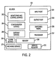
- FIG. 2 is a block diagram showing exemplary components of a router such as router 120, in accordance with an embodiment of the invention.
- Router 120 comprises an input port 251, an output port 253, a switching fabric 255, a processor 257, and a memory 259.
- Input port 251 comprises an interface for receiving input data flows.
- Input port 251 may comprise a plurality online cards, for example.
- Switching fabric 255 conneets input port 251 and output port 253.
- Output port 253 comprises an interface for transmitting output data flows.
- Output port 253 stores packets and transmits packets on respective output links.
- Processor 257 controls the operation of various components of router 120, and may direct data flows according to routing protocols.
- Memory 259 may comprise a non-transitory computer readable medium, such as a magnetic disk, magnetic tape, or optical disk, that includes instructions in the form of computer code that may be executed by processor 257 to perform various functions.
- an automation management system is deployed and operates on a network of network devices within communication system 100, and the system is used to provide automation management services.
- the network devices may comprise a plurality of routers, a plurality of switches, a plurality of hubs, or a combination of different types of network devices.
- an automation management system is deployed and operates on a network of routers (including routers 120, 125) within communication system 100.
- an automation management system is deployed, and operates, using a service-oriented architecture, and is used to deploy and operate automation management services within communication system 100.
- a service-oriented architecture various services are deployed and operate as distinct applications.
- the automation management system is distributed. Accordingly, multiple instances of various services are deployed and operate on various network devices within network 105.
- router 120 For purposes of convenience, various services provided by the automation management system are discussed below with reference to router 120; however, other routers (and/or other network devices) within network 105 may include other instances of the services discussed below.
- router 120 comprises additional components that provide automation management system services within communication system 100.
- a service-oriented architecture is used to provide automation management system services.
- router 120 comprises a monitoring and control service 262, a configuration service 264, a gateway service 266, an alarm service 268, an archiving service 270, and a service registry 272.
- Other components may be included to perform other tasks related to the provision of automation management services.
- Various services operating on router 120 may subscribe to other services on router 120 or to services operating on other routers or network devices.
- Network 105 may comprise one or more additional routers and/or other network devices that comprise components related to the provision of automation management services, and may also comprise one or more routers and/or network devices without such additional components.
- monitoring and control service 262 shown in FIG. 2 is a single instance of monitoring and control service 262
- configuration service 264 shown in FIG. 2 is a single instance of configuration service 264, etc.
- Other instances of monitoring and control service 262, configuration service 264, gateway service 266, alarm service 268, archiving service 270, and service registry 272 may reside and operate on other network devices, such as router 125.
- multiple instances of a particular service may reside and operate on a single network device.
- Multiple instances of a particular service may be deployed and distributed for a variety of reasons. For example, each instance of a service may be responsible for a defined geographical area. Multiple instances of a service may also be deployed to achieve redundancy or to facilitate load balancing:
- services within the automation management system maintain and operate on a process image.
- the process image comprises a plurality of process objects, and a plurality of process values corresponding to values measured by various sensors with communication system 100.
- Use of a process image, process objects, and process values to represent aspects of an area in which an automation management system is employed is known.
- Monitoring and control service 262 performs monitoring and control services, including monitoring data received from sensors 166, 176. Monitoring and control service 262 may also transmit control signals to sensors 166, 176 and actuators 168, 178. For example, monitoring and control module 262 may receive a pressure reading from a sensor 166 within area 160 and determine that the measurement exceeds a predetermined maximum level. In response, monitoring and control module 262 may transmit a signal to an appropriate actuator 168 to cause a valve to open.
- Monitoring and control service 262 may also perform additional services such as data aggregation and optimization. For example, monitoring and control service 262 may monitor an average temperature within area 160, calculated based on data received from multiple sensors. Monitoring and control service 262 may additionally control certain actuators 168 within area 160 to optimize the temperature within a building or within designated areas of a building. Optimization may be performed based on pre-established sets of rules relating to energy consumption, temperature requirements within certain areas of a building, etc. Various other services may subscribe to monitoring and control service 262.
- Configuration service 264 maintains information relating to the topology of the automation management system, and information indicating which service instances are located on which network devices. Configuration service 264 also maintains information relating to the configuration data for each respective service instance (e.g., the process objects making up the part of the process image that the service instance is responsible for managing and the association, if any, of a process object and a service instance where the current state of the process object can be obtained). Configuration service 264 also maintains information relating to the configuration data of each gateway service instance (e.g., an association of a process object to an I/O address), and a set of rules governing how process objects are distributed to various services. Various other services may subscribe to configuration service 264.
- Service registry 272 is a location where services are discoverable. Service registry 272 maintains information indicating what services are available, and the location and/or addresses of various services. Service registry 272 may utilize the UDDI standard or the WS-Discovery standard, for example. Various other services may subscribe to service registry 272.
- Gateway service 266 facilitates communications between various components of router 120 and other devices within communication system 100.
- gateway service 266 may receive data in a first format from base station 161 and reformat the data into a second format used by services within the automation management system.
- gateway service 266 may abstract away details specific to an I/O device and network and expose the current state of a process object according to a common process image model.
- Gateway 266 may be deployed on a component of router 120, such as a controller, I/O device, etc., capable of connecting to I/O devices over specific field networks.
- Various other services may subscribe to gateway service 266.
- Alarm service 268 monitors selected process values and provides alarm notifications to appropriate services or applications in accordance with predefined sets of rules. For example, alarm service 268 may monitor a process value corresponding to a level of water in a tank. When the level exceeds a predetermined limit, alarm service 268 may issue an alarm to another service, indicating that an operator or repair service is to be notified. Various other services may subscribe to alarm service 268.
- Archiving service 270 stores data as instructed by other services or according to predetermined sets of rules. Various other services may subscribe to archiving service 270.
- Each of the services described herein may comprise a software program residing in memory 259 that includes multiple modules or subroutines providing respective services or functions, for example.
- each service may comprise multiple software programs residing on one or more computers.
- each service may comprise hardware (such as an application specific integrated circuit ("ASIC")), or a combination of hardware and software.
- ASIC application specific integrated circuit
- Each service may comprise a non-transitory computer readable medium, such as a magnetic disk, magnetic tape, or optical disk, that includes instructions in the form of computer code operable to perform various functions.
- automated and control service (or alternatively, “AC service”) is used to refer to a service provided within the automation management system described above with reference to FIGS. 1 and 2 .
- FIGS. 3 through 14 are diagrams illustrating aspects of the configuration and operation of various services within an automation management system.
- blocks are used to represent service instances deployed on network devices within network 105.
- Arrows are used to represent interactions, including communications, between a first service instance and a second service instance.
- actions occur in an order indicated by letters "A,” "B,” “C,” etc.
- FIG. 3 is a diagram showing a first scenario for configuring an instance of configuration service 264, in accordance with an embodiment of the invention.
- Configuration service instance 264 makes itself discoverable via service registry 272 (step A). This may be achieved, for example, using one of the standard service discovery mechanisms such as UDDI registry or WS-Discovery.
- an engineering tool client 310 may be used to populate configuration service instance 264 with a set of rules (e.g., described in XML) defining how to distribute process objects (or divide the process image) amongst the various AC service instances.
- the engineering tool client 310 populates configuration service instance 264 with configuration data (e.g., data model and instances of processes)of the processes (i.e., the static process image).
- configuration data e.g., data model and instances of processes
- the configuration data managed by configuration service instance 264 is changed (e.g., by engineering tool 310)
- all affected service instances are notified by configuration service instance 264 (step D). This happens after the change transaction has been successfully completed.
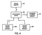
- FIG. 4 is a diagram illustrating a second scenario for configuring configuration service instance 264, in accordance with an embodiment of the-invention.
- configuration service instance 264 makes itself discoverable via service registry 272 (step A). This may be achieved, for example, using one of the standard service discovery mechanisms such as UDDI registry or WS-Discovery.
- service registry 272 This may be achieved, for example, using one of the standard service discovery mechanisms such as UDDI registry or WS-Discovery.
- an instance 266-1 or 266-2 of gateway service 266 is pre-populated with configuration data (i.e., it has its own local configuration data in, e.g., an XML file), then it can populate configuration service instance 264 with this piece of the static process image.
- Configuration service instance 264 must already be pre-populated with its set of rules to distribute the various process objects among AC services. Whenever the configuration data managed by configuration service instance 264 is changed (e.g., adding additional sensor to the layout), all affected service instances (such as AC service instance 470) are notified by configuration service instance 264 (step C). This happens after the change transaction has been successfully completed.
- FIG. 5 is a diagram illustrating a scenario for configuring an AC service instance 525 (AC service Y), in accordance with an embodiment of the invention.
- AC service instance 525 makes itself discoverable via service registry 272 using the same service discovery mechanism discussed above (step A).
- Service Y requests from service registry 272 the location of a configuration service instance (step B).
- Service registry 272 replies with information concerning configuration service instance 264 (step C).
- AC service instance 525 uploads its profile to configuration service instance 264 (i.e., updates to configuration service instance 264 information about AC service instance 525, such as its service endpoint and capabilities).
- AC service instance 525 downloads its configuration data (i.e., the part of the process image it is responsible for) from configuration service instance 264.
- the download may be performed in a manner similar to a synchronization process, by detecting differences, if any, between the current configuration data of AC service instance 525 and the corresponding configuration data for AC service instance 525 stored in configuration service instance 264, and downloading only the difference to AC service 525.
- Step E may also be triggered as a result of a configuration change notification from configuration service instance 264.
- AC service instance 525 may periodically query configuration service instance 264 for changes.
- the configuration data may contain such information as which process objects are managed by AC service instance 525 and where (e.g., in which service instance) the current state of a given process object may be obtained.
- Physical states including raw sensor data
- AC service instance 525 subscribes to respective service instances for process values according to its current configuration data.
- a gateway service instance such as gateway service instance 266, may obtain its configuration data in a manner similar to that shown in FIG. 5 .
- a second scenario for a gateway service instance (such as gateway service instance 266) to obtain its configuration data is shown in FIG. 6 .
- the device hosting gateway service instance 266 is pre-loaded with the configuration data (i.e., it has its own local configuration data in e.g., in an XML file 615). Once the device hosting gateway service instance 266 is connected to the network, it makes itself discoverable (step B).
- gateway service instance 266 requests from service registry 272 the location of a configuration service instance.
- Service registry 272 replies with information concerning configuration service instance 264 (step D).
- gateway service instance 266 uploads its profile (e.g. supported interfaces, support eventing and/or polling) to configuration service instance 264.
- gateway service instance 266 uploads its configuration data to configuration service instance 264.
- the upload process may be a synchronization process where only the difference is uploaded. Step F may be triggered whenever there is a change of configuration in gateway service instance 266 (e.g., a new XML file).
- FIG. 7 is a diagram showing a scenario for configuring an application client 710, in accordance with an embodiment of the invention.
- Application client 710 may reside on a computer operated by an end-user, for example.
- application client 710 requests from service registry 272 the location of a configuration service instance.
- service registry 272 replies with information concerning configuration service instance 264 (step B).
- application client 710 queries configuration service instance 264 to determine where the process objects it is interested in are located.
- configuration service instance 264 returns information concerning one or more AC service instances responsible for that object.
- application client 710 subscribes to the respective AC service instances for the process values.
- redundancy is used to increase the availability and robustness of the automation management system.
- Redundant configuration services are deployed across the network onto multiple network devices, such that multiple network devices each host an instance of the configuration service. When synchronized, all redundant instances of the configuration service will contain the same configuration information.
- FIG. 8 is a diagram showing a first scenario for synchronizing a redundant configuration service, in accordance with an embodiment of the invention.
- the scenario of FIG. 8 may be used when a redundant configuration service joins the network for the first time.
- multiple redundant instances 264-1, 264-2, 264-3, etc., of configuration service 264 reside and operate on various network devices in network 105.
- service instance 264-1 of configuration service 264 connects to the network for the first time via the service discovery mechanism.
- configuration service instance 264-1 requests from service registry 272 the location of all redundant instances of the same service already in network 105 (step B).
- service registry 272 replies with information identifying all redundant configuration service instances (264-2, 264-3, etc.).
- configuration service instance 264-1 selects, based on a load balancing strategy, one of the redundant instances from which to download the latest configuration information (e.g., instance 264-2).
- FIG. 9 is a diagram showing a second scenario for synchronizing a redundant configuration service, in accordance with an embodiment of the invention.
- the second scenario may be used when a change in configuration information requires a configuration service to synchronize across all redundant configuration services.
- synchronization between the redundant service instances is triggered by a specific event such as when the configuration information of a configuration service instance 264-1 is changed (e.g., by an engineering tool).
- configuration service instance 264-1 locates all redundant instances of the same service already in the network (e.g., 264-2, 264-3) via service registry 272 (step-B).
- service registry 272 replies with information identifying all configuration service instances (e.g., 264-2, 264-3).
- configuration service instance 264-1 updates all the redundant service instances (e.g., 264-2, 264-3) with the change (step D). Thereafter, it notifies all the affected service instances (including the redundant service instances) of a configuration information change.
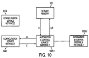
- FIG. 10 is a diagram showing a scenario for deploying a redundant automation and control service service, in accordance with an embodiment of the invention.
- multiple network devices each hosting an instance of the same AC service managing the same piece of process image, are deployed in network 105.
- the AC service instance 1020-1 makes itself discoverable via service registry 272, using the same service discovery mechanism described above.
- AC service instance 1020-1 locates configuration service instance 264-1, using the service discovery mechanism.
- step C when locating configuration service instance 264-1 to update its configuration, AC service instance 1020-1 discovers more than one instance of configuration service 264, since service registry 272 replies with information identifying all instances (e.g., 264-1, 264-2).
- AC service instance 1020-1 selects, based on a load balancing strategy, configuration service instance 264-1 to upload its profile (step D).
- AC service instance 1020-1 downloads its configuration data from configuration service instance 264-1.
- Configuration service instance 264-1 distributes the configuration information to all instances of AC service 1020. Whether a particular instance of AC service 1020 is configured to be instance 1020-2 (redundant to instance 1020-1), or another AC service instance, is determined by configuration service instance 264-1. There is no synchronization between the redundant AC service instances. Each redundant instance behaves as an independent service instance. This is defined in the basic mechanism for AC services.
- FIG. 11 is a diagram showing a scenario for deploying a redundant gateway service 266, in accordance with an embodiment of the invention.
- multiple devices each hosting an instance of gateway service 266 connecting to the same set of I/O devices, are deployed in network 105.
- gateway service instance 266-1 makes itself discoverable via service registry 272, using the same service discovery mechanism described above.
- gateway service instance 266-1 locates configuration service instance 264-1, using the service discovery mechanism.
- gateway service instance 266-1 (one of the redundant AC service instances) discovers more than one instance of configuration service 264, since service registry 272 replies with all instances (e.g., 264-1, 264-2).
- gateway service instance 266-1 selects, based on a load balancing strategy, configuration service instance 264-1 to upload its profile.
- gateway service instance 266-1 uploads its configuration data to configuration service instance 264-1.
- There is no synchronization between the redundant gateway service instances (such as between gateway service instances 266-1 and 266-2). Each redundant instance behaves as an independent service instance, as defined in the basic mechanism for gateway service.
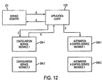
- FIG. 12 is a diagram showing a scenario for deploying a redundant application client 1225, in accordance with an embodiment of the invention.
- application client 1225 locates configuration service instance 264-1 via service registry 272, using the service discovery mechanism.
- service registry 272 replies with all redundant instances of the same service (i.e., 264-1, 264-2).
- application client 1225 selects, based on a load balancing strategy, the redundant instance (e.g., 264-1) to query where a desired process object resides.
- the query returns all redundant instances of the same AC service 1240 responsible for the process object of interest (i.e., 1240-1, 1240-2).
- application client 1225 selects, based on a load balancing strategy, the redundant instance of AC service 1240 to subscribe to for the process object state. In this example, application client 1225 subscribes to AC service instance 1240-1.
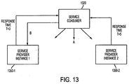
- FIG. 13 is a diagram of a first scenario for achieving load balancing within an automation management system, in accordance with an embodiment of the invention.
- a service consumer 1320 (which may be configuration service 264, another AC service, an application client, etc.) multicasts its request to all redundant instances of the same service provider 1350.
- Various instances 1350-1, 1350-2, etc., of service provider 1350 transmit responses with differing delays measured from the time of the request.
- service consumer 1320 selects the service instance that responded to the multicast request first.
- FIG. 14 is a diagram of a second scenario for achieving load balancing in an automation management system, in accordance with an embodiment of the invention.
- a load level monitor application 1410 monitors load levels among various services.
- load level monitor 1410 sends a report to service registry 272.
- a service consumer 1465 locates an instance of service provider 1420 via service registry 272, using the discovery mechanism (step C).
- service consumer 1465 queries the load levels of all redundant instances of the same service (i.e., 1420-1, 1420-2) and determines the instance with the lowest load (i.e., 1420-1).
- the load level of a service instance may be maintained in the service registry by a load monitoring service or returned by the service instance in response to the multicast request from the consumer.
- service consumer 1465 selects the service provider instance with the lowest load (i.e., 1420-2).
Landscapes
- Engineering & Computer Science (AREA)
- Computer Networks & Wireless Communication (AREA)
- Signal Processing (AREA)
- General Engineering & Computer Science (AREA)
- Manufacturing & Machinery (AREA)
- Quality & Reliability (AREA)
- Physics & Mathematics (AREA)
- General Physics & Mathematics (AREA)
- Automation & Control Theory (AREA)
- Data Exchanges In Wide-Area Networks (AREA)
Description
- This application relates generally to the deployment and operation of an automation management system, and more particularly, to the deployment and operation of an automation management system on a plurality of network devices in a network.
- Automation management systems are used to automate processes in a variety of fields such as manufacturing, the energy industry, and in building management. For example, building management systems are commonly used within buildings and other facilities to manage and control certain building systems such as alarm services, HVAC, lighting, heating, etc. These systems may consist of multiple, integrated subsystems employing large numbers of elements, and are typically controlled by computer. There is a continuing need for improved methods and systems for providing automation management systems services.
-
EP 0973078 discloses a process control system that manages operations of a plant. The system includes various functions, including command and control functions, monitoring functions, data processing functions, etc., distributed on multiple computers connected to a network. These functions control process variables relating to the plant. Lefhalm, C. and Krieger, V., "A Full Featured Monitoring, Control and Data Management System for Liquid Metal Coolant Loops", discloses a modular distribution system providing data management based on connected databases within a laboratory network. A process is separated into distributed control and monitoring stations. Process system components, including software modules and databases, reside on process computers connected to the internal laboratory network. -
U.S. Patent No. 6,263,255 discloses a process control framework that performs automatic process control operations in a semiconductor manufacturing environment. The system includes a software framework that integrates factory, process, and equipment control systems. The architecture includes components for execution and control, fault detection monitoring, documents management, etc. Components are implemented on Windows NT-based platforms. -
U.S. Patent Application No. 2001/0025294 discloses a programmable controller for use in a globally distributed automation network. Programming units residing on devices located at various manufacturing sites are connected to the Internet. The programming units generate and exchange object-oriented software blocks. - In accordance with embodiments of the invention, a system for providing automation management services is provided. The system comprises a plurality of network devices in a network, an automation management system comprising a plurality of services deployed on the network devices in a distributed manner, wherein at least one of the plurality of services comprises a first instance of the service deployed on a first network device and a second instance of the service deployed on a second network device, and wherein the second instance of the at least one of the plurality of services is redundant to the first instance. The system is characterized in that, for synchronizing a redundant configuration service, it further comprises a service registry for providing information to the first instance identifying one or more redundant second instances, wherein the first instance is adapted to select, based on a load balancing strategy, one of the at least one second redundant instance and to download configuration information from the selected redundant second instance.
- In accordance with another embodiment of the invention, a method for providing automation management services is provided. An automation management system, comprising a plurality of services comprising respective applications, operates on a plurality of network devices in a network in a distributed manner, wherein at least one of the services comprises a first instance of the service deployed on a first network device and at least one second instance of the service deployed on a second network device, and wherein the at least one second instance of the at least one of the plurality of services is redundant to the first instance. The method is characterized by the steps of synchronizing a redundant configuration service by performing the steps of receiving, by the first instance, from a service registry, information identifying one or more redundant second instances; selecting, based on a load balancing strategy, one of the at least one second redundant instance; downloading configuration information from the selected redundant second instance; and providing the at least one service with respect to at least one process object within a defined process image. The plurality of network devices may comprise a plurality of routers, for example. The plurality of services may comprise one or more of the following: a monitoring and control service, a configuration service, a gateway service, an alarm service, an archiving service, and a service registry. In one example, the plurality of services comprises a configuration service configured to maintain information relating to a process image. The plurality of services may comprise services relating to one of: a building management system, an industrial automation system, and an energy systems management system.
- Deployment and operation of the automation management system may comprise configuring one or more service instances, wherein an instance of a configuration service in the automation management system is configured by communicating with a registry service operating in the automation management system, by the configuration service instance, in order to make itself discoverable, and populating the configuration service instance with a set of rules defining how to distribute process objects to instances of services.
- Alternatively, deployment and operation of the automation management system may comprise configuring one or more service instances, wherein an instance of an automation and control service in the automation management system is configured by communicating with a registry service operating in the automation management system, by the automation and control service instance, in order to make itself discoverable, and receiving, from the registry service, information identifying a configuration service in the automation system management system. A profile is uploaded to the configuration service, and configuration data is downloaded from the configuration service.
- Alternatively, load balancing is performed within the automation management system by multicasting, by an instance of a first service operating in the automation management system, a request to a plurality of redundant instances of a second service in the automation management system. Responses are received from the plurality of redundant instances, with differing delays, and a service instance is selected based on the received responses. These and other advantages of the present disclosure will be apparent to those of ordinary skill in the art by reference to the following Detailed Description and the accompanying drawings.
-
-
FIG. 1 shows a communication system that may be used to deploy an automation management system, in accordance with an embodiment of the invention; -
FIG. 2 is a block diagram showing exemplary components of a router, in accordance with an exemplary embodiment of the invention; -
FIG. 3 is a diagram showing a first scenario for configuring an instance of a configuration service, in accordance with an embodiment of the invention; -
FIG. 4 is a diagram showing a second scenario for configuring a configuration service instance, in accordance with another embodiment of the invention; -
FIG. 5 is a diagram showing a scenario for configuring an automation and control service instance, in accordance with an embodiment of the invention; -
FIG. 6 is a diagram showing a scenario for configuring a gateway service instance, in accordance with an embodiment of the invention; -
FIG. 7 is a diagram showing a scenario for configuring an application client, in accordance with an embodiment of the invention; -
FIG. 8 is a diagram showing a first scenario for synchronizing a redundant configuration service, in accordance with an embodiment of the invention; -
FIG. 9 is a diagram showing a second scenario for synchronizing a redundant configuration service, in accordance with another embodiment of the invention; -
FIG. 10 is a diagram showing a scenario for deploying a redundant automation and control service, in accordance with an embodiment of the invention; -
FIG. 11 is a diagram showing a scenario for deploying a redundant gateway service, in accordance with an embodiment of the invention; -
FIG. 12 is a diagram showing a scenario for deploying a redundant application client, in accordance with an embodiment of the invention; -
FIG. 13 is a diagram showing a first scenario for achieving load balancing within an automation management system, in accordance with an embodiment of the invention; and -
FIG. 14 is a diagram showing a second scenario for achieving load balancing in an automation management system, in accordance with another embodiments of the invention. - In accordance with an embodiment of the invention, a system for providing automation management services is provided. The system comprises a plurality of network devices in a network, and an automation management system deployed and operating on the network devices in a distributed manner. A network device may be a router, a switch, a hub, etc. Automation management services are deployed and operate on the network devices in accordance with a service-oriented architecture model.
-
FIG. 1 shows acommunication system 100 that may be used to deploy and operate an automation management system, in accordance with an embodiment of the invention.Communication system 100 comprises anetwork 105, afirst area 160 and asecond area 170. -
Network 105 comprises a plurality ofnodes 115 connected bylinks 118. Eachnode 115 comprises at least one network device capable of receiving, sending and forwarding information withinnetwork 105. The plurality of network devices withinnetwork 105 are linked withinnetwork 105, forming a network of network devices. - In the exemplary embodiment of
FIG. 1 ,network 105 comprises a plurality of routers, of which two (routers 120, 125) are shown. The plurality of routers withinnetwork 105 are linked withinnetwork 105, forming a network of routers. While two routers are shown inFIG. 1 ,network 105 may include any number of routers. In addition to routers,network 105 may also comprise any number of other network devices, such as switches, hubs, etc. -
Network 105 may comprise one or more of a number of different types of networks, such as, for example, the Internet, an intranet, a local area network (LAN), a wide area network (WAN), an internet, Fibre Channel-based storage area network (SAN) or Ethernet. Other networks may be used. Alternatively,network 105 may comprise a combination of different types of networks. -
Area 160 is a first location in which an automation management system is deployed and operates to manage and control one or more processes.Area 160 comprises a plurality ofsensors 166 used to measure selected aspects of area 160 (such as the speed of a fan, a water level in a tank, a temperature of a room, etc.) and a plurality ofactuators 168, such as switches, used to control devices. In this example,sensors 166 andactuators 168 are connected to network 105 via abase station 161. Alternatively,sensors 166 andactuators 168 may be connected to network 105 via a programmable logic controller ("PLC"), a field control panel, a terminal equipment controller ("TEC"), or other device. -
Area 170 is a second location comprising a plurality ofsensors 176 used to measure selected aspects of area 170 (such as the speed of a fan, a water level in a tank, a temperature of a room, etc.) and a plurality ofactuators 178, such as switches, used to control devices. In the embodiment ofFIG. 1 ,sensors 176 andactuators 178 are connected directly tonetwork 105 and communicate with devices withinnetwork 105 using appropriate protocols such as IP protocols. - In an exemplary embodiment,
area 160 is a first building andarea 170 is a second building.Areas communication system 100 is used to provide building management services (and other types of automation management services) to manage and control various systems withinareas areas areas communication system 100 is used to provide automation management systems services relating to industrial automation system management, energy systems management, management of energy consumption within residential neighborhoods, etc. - Routers, and use of routers in a communication system, are well-known.
Router 120 facilitates the transmission of communication signals between various components withincommunication system 100.Router 120 may comprise hardware, software, or a combination of hardware and software. In one embodiment,router 120 may be an Integrated Services Router (ISR) that supports Application extension Platform (AXP), available from Cisco Systems, Inc. of San Jose, California. -
Router 120 may receive data flows in the form of packets. Packets may comprise information identifying a destination component external torouter 120. The packets may comprise, for example, Internet Protocol (IP) packets or Transmission Control Protocol (TCP) packets. IP packets and TCP packets are structured based on known IP and TCP packet protocols. However, packets employed in data flows between network devices incommunication system 100 may be structured using other network packet protocols. -
FIG. 2 is a block diagram showing exemplary components of a router such asrouter 120, in accordance with an embodiment of the invention.Router 120 comprises aninput port 251, anoutput port 253, a switchingfabric 255, aprocessor 257, and amemory 259.Input port 251 comprises an interface for receiving input data flows.Input port 251 may comprise a plurality online cards, for example.Switching fabric 255conneets input port 251 andoutput port 253.Output port 253 comprises an interface for transmitting output data flows.Output port 253 stores packets and transmits packets on respective output links.Processor 257 controls the operation of various components ofrouter 120, and may direct data flows according to routing protocols.Memory 259 may comprise a non-transitory computer readable medium, such as a magnetic disk, magnetic tape, or optical disk, that includes instructions in the form of computer code that may be executed byprocessor 257 to perform various functions. - In accordance with an embodiment of the invention, an automation management system is deployed and operates on a network of network devices within
communication system 100, and the system is used to provide automation management services. The network devices may comprise a plurality of routers, a plurality of switches, a plurality of hubs, or a combination of different types of network devices. In the exemplary embodiment ofFIG. 1 , an automation management system is deployed and operates on a network of routers (includingrouters 120, 125) withincommunication system 100. - In the exemplary embodiment, an automation management system is deployed, and operates, using a service-oriented architecture, and is used to deploy and operate automation management services within
communication system 100. Using a service-oriented architecture, various services are deployed and operate as distinct applications. In addition, the automation management system is distributed. Accordingly, multiple instances of various services are deployed and operate on various network devices withinnetwork 105. - For purposes of convenience, various services provided by the automation management system are discussed below with reference to
router 120; however, other routers (and/or other network devices) withinnetwork 105 may include other instances of the services discussed below. - In accordance with an embodiment of the invention,
router 120 comprises additional components that provide automation management system services withincommunication system 100. As discussed above, a service-oriented architecture is used to provide automation management system services. In the exemplary embodiment shown inFIG. 2 ,router 120 comprises a monitoring andcontrol service 262, aconfiguration service 264, agateway service 266, analarm service 268, anarchiving service 270, and aservice registry 272. Other components may be included to perform other tasks related to the provision of automation management services. Various services operating onrouter 120 may subscribe to other services onrouter 120 or to services operating on other routers or network devices.Network 105 may comprise one or more additional routers and/or other network devices that comprise components related to the provision of automation management services, and may also comprise one or more routers and/or network devices without such additional components. - In the exemplary embodiment of
FIG. 1 , the automation management system is distributed and redundant. Thus, monitoring andcontrol service 262 shown inFIG. 2 is a single instance of monitoring andcontrol service 262,configuration service 264 shown inFIG. 2 is a single instance ofconfiguration service 264, etc. Other instances of monitoring andcontrol service 262,configuration service 264,gateway service 266,alarm service 268,archiving service 270, andservice registry 272 may reside and operate on other network devices, such asrouter 125. In some embodiments, multiple instances of a particular service may reside and operate on a single network device. Multiple instances of a particular service may be deployed and distributed for a variety of reasons. For example, each instance of a service may be responsible for a defined geographical area. Multiple instances of a service may also be deployed to achieve redundancy or to facilitate load balancing: - In an embodiment of the invention, services within the automation management system maintain and operate on a process image. The process image comprises a plurality of process objects, and a plurality of process values corresponding to values measured by various sensors with
communication system 100. Use of a process image, process objects, and process values to represent aspects of an area in which an automation management system is employed is known. - Monitoring and
control service 262 performs monitoring and control services, including monitoring data received fromsensors control service 262 may also transmit control signals tosensors actuators control module 262 may receive a pressure reading from asensor 166 withinarea 160 and determine that the measurement exceeds a predetermined maximum level. In response, monitoring andcontrol module 262 may transmit a signal to anappropriate actuator 168 to cause a valve to open. - Monitoring and
control service 262 may also perform additional services such as data aggregation and optimization. For example, monitoring andcontrol service 262 may monitor an average temperature withinarea 160, calculated based on data received from multiple sensors. Monitoring andcontrol service 262 may additionally controlcertain actuators 168 withinarea 160 to optimize the temperature within a building or within designated areas of a building. Optimization may be performed based on pre-established sets of rules relating to energy consumption, temperature requirements within certain areas of a building, etc. Various other services may subscribe to monitoring andcontrol service 262. -
Configuration service 264 maintains information relating to the topology of the automation management system, and information indicating which service instances are located on which network devices.Configuration service 264 also maintains information relating to the configuration data for each respective service instance (e.g., the process objects making up the part of the process image that the service instance is responsible for managing and the association, if any, of a process object and a service instance where the current state of the process object can be obtained).Configuration service 264 also maintains information relating to the configuration data of each gateway service instance (e.g., an association of a process object to an I/O address), and a set of rules governing how process objects are distributed to various services. Various other services may subscribe toconfiguration service 264. -
Service registry 272 is a location where services are discoverable.Service registry 272 maintains information indicating what services are available, and the location and/or addresses of various services.Service registry 272 may utilize the UDDI standard or the WS-Discovery standard, for example. Various other services may subscribe toservice registry 272. -
Gateway service 266 facilitates communications between various components ofrouter 120 and other devices withincommunication system 100. For example,gateway service 266 may receive data in a first format frombase station 161 and reformat the data into a second format used by services within the automation management system. For example,gateway service 266 may abstract away details specific to an I/O device and network and expose the current state of a process object according to a common process image model.Gateway 266 may be deployed on a component ofrouter 120, such as a controller, I/O device, etc., capable of connecting to I/O devices over specific field networks. Various other services may subscribe togateway service 266. -
Alarm service 268 monitors selected process values and provides alarm notifications to appropriate services or applications in accordance with predefined sets of rules. For example,alarm service 268 may monitor a process value corresponding to a level of water in a tank. When the level exceeds a predetermined limit,alarm service 268 may issue an alarm to another service, indicating that an operator or repair service is to be notified. Various other services may subscribe to alarmservice 268. -
Archiving service 270 stores data as instructed by other services or according to predetermined sets of rules. Various other services may subscribe toarchiving service 270. - Each of the services described herein may comprise a software program residing in
memory 259 that includes multiple modules or subroutines providing respective services or functions, for example. In other embodiments, each service may comprise multiple software programs residing on one or more computers. In alternative embodiments, each service may comprise hardware (such as an application specific integrated circuit ("ASIC")), or a combination of hardware and software. Each service may comprise a non-transitory computer readable medium, such as a magnetic disk, magnetic tape, or optical disk, that includes instructions in the form of computer code operable to perform various functions. - Methods and systems for deploying and operating an automation management system on a network of network devices are described below. In the discussion below, the term "automation and control service," (or alternatively, "AC service") is used to refer to a service provided within the automation management system described above with reference to
FIGS. 1 and2 . - In accordance with embodiments of the invention, deployment and operation of an automation management system within
communication system 100 requires deploying and configuring services on network devices innetwork 105. Multiple instances of a particular service may be deployed and configured on a plurality of network devices.FIGS. 3 through 14 are diagrams illustrating aspects of the configuration and operation of various services within an automation management system. InFIGS. 3 through 14 , blocks are used to represent service instances deployed on network devices withinnetwork 105. Arrows are used to represent interactions, including communications, between a first service instance and a second service instance. In each diagram, actions occur in an order indicated by letters "A," "B," "C," etc. - After a network device, such as
router 120, that hosts an instance ofconfiguration service 264 is connected to network 105, the configuration service instance must be configured.FIG. 3 is a diagram showing a first scenario for configuring an instance ofconfiguration service 264, in accordance with an embodiment of the invention.Configuration service instance 264 makes itself discoverable via service registry 272 (step A). This may be achieved, for example, using one of the standard service discovery mechanisms such as UDDI registry or WS-Discovery. At step B, anengineering tool client 310 may be used to populateconfiguration service instance 264 with a set of rules (e.g., described in XML) defining how to distribute process objects (or divide the process image) amongst the various AC service instances. At step C, theengineering tool client 310 populatesconfiguration service instance 264 with configuration data (e.g., data model and instances of processes)of the processes (i.e., the static process image). Whenever the configuration data managed byconfiguration service instance 264 is changed (e.g., by engineering tool 310), all affected service instances (such as AC service 340) are notified by configuration service instance 264 (step D). This happens after the change transaction has been successfully completed. -
FIG. 4 is a diagram illustrating a second scenario for configuringconfiguration service instance 264, in accordance with an embodiment of the-invention. Oncerouter 120 hostingconfiguration service instance 264 is connected to network 105,configuration service instance 264 makes itself discoverable via service registry 272 (step A). This may be achieved, for example, using one of the standard service discovery mechanisms such as UDDI registry or WS-Discovery. At step B, if an instance 266-1 or 266-2 ofgateway service 266 is pre-populated with configuration data (i.e., it has its own local configuration data in, e.g., an XML file), then it can populateconfiguration service instance 264 with this piece of the static process image.Configuration service instance 264 must already be pre-populated with its set of rules to distribute the various process objects among AC services. Whenever the configuration data managed byconfiguration service instance 264 is changed (e.g., adding additional sensor to the layout), all affected service instances (such as AC service instance 470) are notified by configuration service instance 264 (step C). This happens after the change transaction has been successfully completed. - After a network device, such as
router 120, that hosts an instance of an AC service is connected to network 105, the AC service instance must be configured.FIG. 5 is a diagram illustrating a scenario for configuring an AC service instance 525 (AC service Y), in accordance with an embodiment of the invention.AC service instance 525 makes itself discoverable viaservice registry 272 using the same service discovery mechanism discussed above (step A). Service Y requests fromservice registry 272 the location of a configuration service instance (step B).Service registry 272 replies with information concerning configuration service instance 264 (step C). At step D,AC service instance 525 uploads its profile to configuration service instance 264 (i.e., updates toconfiguration service instance 264 information aboutAC service instance 525, such as its service endpoint and capabilities). IfAC service instance 525 is momentarily disconnected fromnetwork 105, then its information inconfiguration service instance 264 may still remain unchanged. At step E,AC service instance 525 downloads its configuration data (i.e., the part of the process image it is responsible for) fromconfiguration service instance 264. For reasons of efficiency, the download may be performed in a manner similar to a synchronization process, by detecting differences, if any, between the current configuration data ofAC service instance 525 and the corresponding configuration data forAC service instance 525 stored inconfiguration service instance 264, and downloading only the difference toAC service 525. Step E may also be triggered as a result of a configuration change notification fromconfiguration service instance 264. To increase robustness,AC service instance 525 may periodically queryconfiguration service instance 264 for changes. The configuration data may contain such information as which process objects are managed byAC service instance 525 and where (e.g., in which service instance) the current state of a given process object may be obtained. Physical states (including raw sensor data) are usually obtained from gateway services, but there may also be computed states from any service instance. At step F,AC service instance 525 subscribes to respective service instances for process values according to its current configuration data. - After a network device, such as
router 120, that hosts an instance ofgateway service 266 is connected to network 105, the gateway service instance must be configured. In accordance with a first scenario, a gateway service instance, such asgateway service instance 266, may obtain its configuration data in a manner similar to that shown inFIG. 5 . A second scenario for a gateway service instance (such as gateway service instance 266) to obtain its configuration data is shown inFIG. 6 . At step A, the device hostinggateway service instance 266 is pre-loaded with the configuration data (i.e., it has its own local configuration data in e.g., in an XML file 615). Once the device hostinggateway service instance 266 is connected to the network, it makes itself discoverable (step B). At step C,gateway service instance 266 requests fromservice registry 272 the location of a configuration service instance.Service registry 272 replies with information concerning configuration service instance 264 (step D). At step E,gateway service instance 266 uploads its profile (e.g. supported interfaces, support eventing and/or polling) toconfiguration service instance 264. At step F,gateway service instance 266 uploads its configuration data toconfiguration service instance 264. As described above, the upload process may be a synchronization process where only the difference is uploaded. Step F may be triggered whenever there is a change of configuration in gateway service instance 266 (e.g., a new XML file). -
FIG. 7 is a diagram showing a scenario for configuring anapplication client 710, in accordance with an embodiment of the invention.Application client 710 may reside on a computer operated by an end-user, for example. At step A,application client 710 requests fromservice registry 272 the location of a configuration service instance. At step B,service registry 272 replies with information concerning configuration service instance 264 (step B). At step C,application client 710 queriesconfiguration service instance 264 to determine where the process objects it is interested in are located. At step D, for each process object of interest,configuration service instance 264 returns information concerning one or more AC service instances responsible for that object. At step E,application client 710 subscribes to the respective AC service instances for the process values. - In accordance with an embodiment of the invention, redundancy is used to increase the availability and robustness of the automation management system. Redundant configuration services are deployed across the network onto multiple network devices, such that multiple network devices each host an instance of the configuration service. When synchronized, all redundant instances of the configuration service will contain the same configuration information.
-
FIG. 8 is a diagram showing a first scenario for synchronizing a redundant configuration service, in accordance with an embodiment of the invention. The scenario ofFIG. 8 may be used when a redundant configuration service joins the network for the first time. In this embodiment, multiple redundant instances 264-1, 264-2, 264-3, etc., ofconfiguration service 264 reside and operate on various network devices innetwork 105. At step A, service instance 264-1 ofconfiguration service 264 connects to the network for the first time via the service discovery mechanism. As a result, configuration service instance 264-1 requests fromservice registry 272 the location of all redundant instances of the same service already in network 105 (step B). At step C,service registry 272 replies with information identifying all redundant configuration service instances (264-2, 264-3, etc.). If the trigger for synchronization is on account of configuration service instance 264-1 connecting to the network, then configuration service instance 264-1 selects, based on a load balancing strategy, one of the redundant instances from which to download the latest configuration information (e.g., instance 264-2). -
FIG. 9 is a diagram showing a second scenario for synchronizing a redundant configuration service, in accordance with an embodiment of the invention. The second scenario may be used when a change in configuration information requires a configuration service to synchronize across all redundant configuration services. At step A, synchronization between the redundant service instances is triggered by a specific event such as when the configuration information of a configuration service instance 264-1 is changed (e.g., by an engineering tool). Upon such an event, configuration service instance 264-1 locates all redundant instances of the same service already in the network (e.g., 264-2, 264-3) via service registry 272 (step-B). At step C,service registry 272 replies with information identifying all configuration service instances (e.g., 264-2, 264-3). If the trigger for synchronization is on account of a change in configuration information in configuration service instance 264-1, then configuration service instance 264-1 updates all the redundant service instances (e.g., 264-2, 264-3) with the change (step D). Thereafter, it notifies all the affected service instances (including the redundant service instances) of a configuration information change. -
FIG. 10 is a diagram showing a scenario for deploying a redundant automation and control service service, in accordance with an embodiment of the invention. In this embodiment, multiple network devices, each hosting an instance of the same AC service managing the same piece of process image, are deployed innetwork 105. At step A, the AC service instance 1020-1 makes itself discoverable viaservice registry 272, using the same service discovery mechanism described above. At step B, AC service instance 1020-1 locates configuration service instance 264-1, using the service discovery mechanism. At step C, when locating configuration service instance 264-1 to update its configuration, AC service instance 1020-1 discovers more than one instance ofconfiguration service 264, sinceservice registry 272 replies with information identifying all instances (e.g., 264-1, 264-2). AC service instance 1020-1 selects, based on a load balancing strategy, configuration service instance 264-1 to upload its profile (step D). At step E, AC service instance 1020-1 downloads its configuration data from configuration service instance 264-1. Configuration service instance 264-1 distributes the configuration information to all instances of AC service 1020. Whether a particular instance of AC service 1020 is configured to be instance 1020-2 (redundant to instance 1020-1), or another AC service instance, is determined by configuration service instance 264-1. There is no synchronization between the redundant AC service instances. Each redundant instance behaves as an independent service instance. This is defined in the basic mechanism for AC services. -
FIG. 11 is a diagram showing a scenario for deploying aredundant gateway service 266, in accordance with an embodiment of the invention. In this embodiment, multiple devices, each hosting an instance ofgateway service 266 connecting to the same set of I/O devices, are deployed innetwork 105. At step A, gateway service instance 266-1 makes itself discoverable viaservice registry 272, using the same service discovery mechanism described above. At step B, gateway service instance 266-1 locates configuration service instance 264-1, using the service discovery mechanism. At step C, when locatingconfiguration service instance 264 to update its configuration, gateway service instance 266-1 (one of the redundant AC service instances) discovers more than one instance ofconfiguration service 264, sinceservice registry 272 replies with all instances (e.g., 264-1, 264-2). At step D, gateway service instance 266-1 selects, based on a load balancing strategy, configuration service instance 264-1 to upload its profile. At step E, gateway service instance 266-1 uploads its configuration data to configuration service instance 264-1. There is no synchronization between the redundant gateway service instances (such as between gateway service instances 266-1 and 266-2). Each redundant instance behaves as an independent service instance, as defined in the basic mechanism for gateway service. -
FIG. 12 is a diagram showing a scenario for deploying aredundant application client 1225, in accordance with an embodiment of the invention. At step A,application client 1225 locates configuration service instance 264-1 viaservice registry 272, using the service discovery mechanism. At step B,service registry 272 replies with all redundant instances of the same service (i.e., 264-1, 264-2). At step C,application client 1225 selects, based on a load balancing strategy, the redundant instance (e.g., 264-1) to query where a desired process object resides. At step D, the query returns all redundant instances of the same AC service 1240 responsible for the process object of interest (i.e., 1240-1, 1240-2). At step E,application client 1225 selects, based on a load balancing strategy, the redundant instance of AC service 1240 to subscribe to for the process object state. In this example,application client 1225 subscribes to AC service instance 1240-1. - Performance in a redundant system can be increased by load balancing between redundant service instances.
FIG. 13 is a diagram of a first scenario for achieving load balancing within an automation management system, in accordance with an embodiment of the invention. At step A, a service consumer 1320 (which may beconfiguration service 264, another AC service, an application client, etc.) multicasts its request to all redundant instances of the same service provider 1350. Various instances 1350-1, 1350-2, etc., of service provider 1350 transmit responses with differing delays measured from the time of the request. At step B,service consumer 1320 selects the service instance that responded to the multicast request first. -
FIG. 14 is a diagram of a second scenario for achieving load balancing in an automation management system, in accordance with an embodiment of the invention. At step A, a loadlevel monitor application 1410 monitors load levels among various services. At step B,load level monitor 1410 sends a report toservice registry 272. At any time, aservice consumer 1465 locates an instance of service provider 1420 viaservice registry 272, using the discovery mechanism (step C). At step D,service consumer 1465 queries the load levels of all redundant instances of the same service (i.e., 1420-1, 1420-2) and determines the instance with the lowest load (i.e., 1420-1). The load level of a service instance may be maintained in the service registry by a load monitoring service or returned by the service instance in response to the multicast request from the consumer. At step E,service consumer 1465 selects the service provider instance with the lowest load (i.e., 1420-2).
Claims (10)
- A system for providing automation management services, the system comprising:a plurality of network devices (120, 125) in a network (105);an automation management system comprising a plurality of services (262, 264, 266, 268, 270, 272) deployed on the network devices (120, 125) in a distributed manner, wherein at least one of the plurality of services (262, 264, 266, 268, 270, 272) comprises a first instance (264-1) of the service deployed on a first network device (120, 125) and a second instance (264-2) of the service deployed on a second network device (120, 125), and wherein the second instance (264-2) of the at least one of the plurality of services (262, 264, 266, 268, 270, 272) is redundant to the first instance (264-1);
characterized in that for synchronizing a redundant configuration service (264) the system further comprisesa service registry (272) for providing information to the first instance (264-1) identifying one or more redundant second instances (264-2), wherein the first instance (264-1) is adapted to select, based on a load balancing strategy, one of the at least one second redundant instance (264-2) and to download configuration information from the selected redundant second instance (264-2). - The system of claim 1, wherein each of the plurality of services (262, 264, 266, 268, 270, 272) comprises a distinct application deployed on the network devices (120, 125).
- A method for providing automation management services, the method comprising:operating an automation management system, comprising a plurality of services (262, 264, 266, 268, 270, 272) comprising respective applications, on a plurality of network devices (120, 125) in a network in a distributed manner, wherein at least one of the services (262, 264, 266, 268, 270, 272) comprises a first instance (264-1) of the service deployed on a first network device (120, 125) and at least one second instance (264-2) of the service deployed on a second network device (120, 125), and wherein the at least one second instance (264-2) of the at least one of the plurality of services (262, 264, 266, 268, 270, 272) is redundant to the first instance (264-1);characterized by the steps of:synchronizing a redundant configuration service (264) by performing the steps of:receiving, by the first instance (264-1), from a service registry (272), information identifying one or more redundant second instances (264-2);selecting, based on a load balancing strategy, one of the at least one second redundant instance (264-2);downloading configuration information from the selected redundant second instance (264-2); andproviding the at least one service with respect to at least one process object within a defined process image.
- The method of claim 3, or the system of claim 1, wherein the plurality of services (262, 264, 266, 268, 270, 272) comprise at least one of: a monitoring and control service (262), a configuration service (264), a gateway service (266), an alarm service (268), an archiving service (270), and a service registry (272).
- The method of claim 4, or the system of claim 1, wherein the plurality of services (262, 264, 266, 268, 270, 272) comprise a configuration service (264) configured to maintain information relating to a process image.
- The method of claim 3, or the system of claim 1, wherein the plurality of services (262, 264, 266, 268, 270, 272) comprises services relating to one of: a building management system, an industrial automation system, and an energy systems management system.
- The method of claim 3, further comprising configuring an instance of a configuration service (264) in the automation management system by performing the following steps:communicating with a registry service (272) operating in the automation management system, by a configuration service instance (264), in order to make itself discoverable; andpopulating the configuration service (264) instance with a set of rules defining how to distribute process objects to instances of services.
- The method of claim 3, further comprising configuring an instance of an automation and control service (340) in the automation management system by performing the following steps:communicating with a registry service (272) operating in the automation management system, by an instance of an automation and control service (340), in order to make itself discoverable;receiving, by the automation and control service instance (340), information identifying a configuration service (264) in the automation system management system;uploading a profile to the configuration service (264); and downloading configuration data from the configuration service (264).
- The method of claim 3, further comprising performing load balancing within the automation management system by performing the following steps:multicasting, by an instance of a first service (1240) operating in the automation management system, a request to a plurality of redundant instances of a second service (264-1, 264-2, 264-3) in the automation management system;receiving, from the plurality of redundant instances (264-1, 264-2, 264-3), responses with differing delays; andselecting a service instance based on the received responses.
- The method of claim 3, or the system of claim 1, wherein the plurality of network devices (120, 125) comprises a plurality of routers (120, 125).
Applications Claiming Priority (3)
| Application Number | Priority Date | Filing Date | Title |
|---|---|---|---|
| US22223709P | 2009-07-01 | 2009-07-01 | |
| US12/827,086 US8326962B2 (en) | 2009-07-01 | 2010-06-30 | Method, system and apparatus for providing automation management services |
| PCT/US2010/040700 WO2011002954A1 (en) | 2009-07-01 | 2010-07-01 | Method, system and apparatus for providing automation management services |
Publications (2)
| Publication Number | Publication Date |
|---|---|
| EP2449725A1 EP2449725A1 (en) | 2012-05-09 |
| EP2449725B1 true EP2449725B1 (en) | 2016-11-02 |
Family
ID=42635083
Family Applications (1)
| Application Number | Title | Priority Date | Filing Date |
|---|---|---|---|
| EP10740782.7A Active EP2449725B1 (en) | 2009-07-01 | 2010-07-01 | Method, system and apparatus for providing automation management services |
Country Status (8)
| Country | Link |
|---|---|
| US (1) | US8326962B2 (en) |
| EP (1) | EP2449725B1 (en) |
| KR (1) | KR101369373B1 (en) |
| CN (1) | CN102484599B (en) |
| BR (1) | BRPI1011923B1 (en) |
| CA (1) | CA2766962C (en) |
| MX (1) | MX2012000255A (en) |
| WO (1) | WO2011002954A1 (en) |
Families Citing this family (15)
| Publication number | Priority date | Publication date | Assignee | Title |
|---|---|---|---|---|
| US20100281387A1 (en) * | 2009-05-01 | 2010-11-04 | Johnson Controls Technology Company | Systems and methods for managing building automation systems and it systems |
| US8326962B2 (en) * | 2009-07-01 | 2012-12-04 | Siemens Corporation | Method, system and apparatus for providing automation management services |
| JP5601353B2 (en) * | 2012-06-29 | 2014-10-08 | 横河電機株式会社 | Network management system |
| US9667470B2 (en) | 2012-09-07 | 2017-05-30 | Oracle International Corporation | Failure handling in the execution flow of provisioning operations in a cloud environment |
| US10521746B2 (en) | 2012-09-07 | 2019-12-31 | Oracle International Corporation | Recovery workflow for processing subscription orders in a computing infrastructure system |
| US9838370B2 (en) | 2012-09-07 | 2017-12-05 | Oracle International Corporation | Business attribute driven sizing algorithms |
| US9621435B2 (en) | 2012-09-07 | 2017-04-11 | Oracle International Corporation | Declarative and extensible model for provisioning of cloud based services |
| US9501541B2 (en) | 2012-09-07 | 2016-11-22 | Oracle International Corporation | Separation of pod provisioning and service provisioning |
| US9253113B2 (en) | 2012-09-07 | 2016-02-02 | Oracle International Corporation | Customizable model for throttling and prioritizing orders in a cloud environment |
| US10148530B2 (en) * | 2012-09-07 | 2018-12-04 | Oracle International Corporation | Rule based subscription cloning |
| US9001697B2 (en) * | 2012-12-14 | 2015-04-07 | Western Digital Technologies, Inc. | Methods and devices for replacing and configuring a router in a network |
| US8924899B2 (en) | 2013-05-23 | 2014-12-30 | Daniel Jakob Seidner | System and method for universal control of electronic devices |
| CN105324728B (en) * | 2013-06-11 | 2019-06-07 | 西门子公司 | Industrial control system for monitoring automation factory |
| US10142174B2 (en) | 2015-08-25 | 2018-11-27 | Oracle International Corporation | Service deployment infrastructure request provisioning |
| EP3598255B1 (en) * | 2018-07-17 | 2022-01-26 | Siemens Aktiengesellschaft | Arrangement with operator servers and with operator clients |
Family Cites Families (17)
| Publication number | Priority date | Publication date | Assignee | Title |
|---|---|---|---|---|
| HUP9900247A3 (en) | 1996-01-17 | 1999-12-28 | Siemens Ag | Automation device, programing device, operating and monitoring device adapted in the automation device, as well as an intelligent field device |
| US6115646A (en) * | 1997-12-18 | 2000-09-05 | Nortel Networks Limited | Dynamic and generic process automation system |
| US6216173B1 (en) * | 1998-02-03 | 2001-04-10 | Redbox Technologies Limited | Method and apparatus for content processing and routing |
| US6263255B1 (en) | 1998-05-18 | 2001-07-17 | Advanced Micro Devices, Inc. | Advanced process control for semiconductor manufacturing |
| US6571273B1 (en) | 1998-07-13 | 2003-05-27 | Yokogawa Electric Corporation | Process control system |
| US6687220B1 (en) * | 1999-09-28 | 2004-02-03 | Ericsson Inc. | Quality of service management in a packet data router having multiple virtual router instances |
| US6973622B1 (en) * | 2000-09-25 | 2005-12-06 | Wireless Valley Communications, Inc. | System and method for design, tracking, measurement, prediction and optimization of data communication networks |
| US7436937B2 (en) * | 2001-09-26 | 2008-10-14 | Clawson Jeffrey J | Method and system for the police response dispatch protocol of an emergency dispatch system |
| CA2467939A1 (en) * | 2004-05-20 | 2005-11-20 | Fernando Cuervo | Architecture for configuration and management of cross-domain network services |
| US20070008970A1 (en) * | 2005-06-28 | 2007-01-11 | Utstarcom, Inc. | Packet data router apparatus and method |
| CN1848787A (en) * | 2006-04-30 | 2006-10-18 | 西安交通大学 | Automatic fast dispositioning method for aggregated server system node |
| US20070276948A1 (en) * | 2006-05-24 | 2007-11-29 | Sap Ag | System and method for automated configuration and deployment of applications |
| CN101453367B (en) * | 2007-11-30 | 2011-12-28 | 华为技术有限公司 | Software deployment method and system, software deployment server and user server |
| US20090252173A1 (en) * | 2008-04-03 | 2009-10-08 | Rangaprasad Sampath | Method For Improving Efficiency Of Redundancy Protocols |
| US20100235914A1 (en) * | 2009-03-13 | 2010-09-16 | Alcatel Lucent | Intrusion detection for virtual layer-2 services |
| US8040822B2 (en) * | 2009-06-04 | 2011-10-18 | Alcatel Lucent | Configuring communication services using policy groups |
| US8326962B2 (en) * | 2009-07-01 | 2012-12-04 | Siemens Corporation | Method, system and apparatus for providing automation management services |
-
2010
- 2010-06-30 US US12/827,086 patent/US8326962B2/en active Active
- 2010-07-01 MX MX2012000255A patent/MX2012000255A/en active IP Right Grant
- 2010-07-01 WO PCT/US2010/040700 patent/WO2011002954A1/en not_active Ceased
- 2010-07-01 EP EP10740782.7A patent/EP2449725B1/en active Active
- 2010-07-01 BR BRPI1011923-0A patent/BRPI1011923B1/en active IP Right Grant
- 2010-07-01 CN CN201080038880.1A patent/CN102484599B/en active Active
- 2010-07-01 CA CA2766962A patent/CA2766962C/en active Active
- 2010-07-01 KR KR1020127002795A patent/KR101369373B1/en active Active
Also Published As
| Publication number | Publication date |
|---|---|
| KR20120031303A (en) | 2012-04-02 |
| US8326962B2 (en) | 2012-12-04 |
| CN102484599A (en) | 2012-05-30 |
| CA2766962A1 (en) | 2011-01-06 |
| KR101369373B1 (en) | 2014-03-04 |
| US20110004679A1 (en) | 2011-01-06 |
| WO2011002954A1 (en) | 2011-01-06 |
| CN102484599B (en) | 2015-09-23 |
| BRPI1011923A2 (en) | 2016-04-19 |
| CA2766962C (en) | 2017-08-01 |
| BRPI1011923B1 (en) | 2021-02-23 |
| MX2012000255A (en) | 2012-01-27 |
| EP2449725A1 (en) | 2012-05-09 |
Similar Documents
| Publication | Publication Date | Title |
|---|---|---|
| CA2766962C (en) | Method, system and apparatus for providing automation management services | |
| US11409514B2 (en) | Building management system with plug and play device registration and configuration | |
| US20240380633A1 (en) | Building management system with adapting iot hub | |
| US7151966B1 (en) | System and methodology providing open interface and distributed processing in an industrial controller environment | |
| JP5749982B2 (en) | System for controlling the distribution network | |
| EP1492310A2 (en) | Industrial equipment network | |
| AU2016369256A1 (en) | Apparatus and method for using an internet of things edge secure gateway | |
| US10412041B2 (en) | Internet protocol (IP) addressing using an industrial control program | |
| US7606890B1 (en) | System and methodology providing namespace and protocol management in an industrial controller environment | |
| GB2626215A (en) | Industrial control system architecture for real-time simulation and process control | |
| CN108183935B (en) | Method for providing network communication between IP devices via internet | |
| WO2019071238A2 (en) | Building management system with cloud-based data platform | |
| US20190107831A1 (en) | Building management system with gateway device status messaging and display | |
| JP6419389B2 (en) | Method for setting modular control device of industrial automation system and modular control device | |
| US20240118798A1 (en) | Configuration sourced direct from ethernet advanced physical layer field device | |
| KR102482540B1 (en) | Distributed Control Method And Distributed Control System Of Network-Based Plant Process Control System | |
| KR20070119013A (en) | Device Device and Profile Transfer Method in Network System | |
| US6996600B2 (en) | System and method for servicing messages between device controller nodes and via a lon network | |
| AU2023200276C1 (en) | Modular control network architecture | |
| JP4039457B2 (en) | IDENTIFICATION INFORMATION AUTOMATIC GENERATION DEVICE, INFORMATION STORAGE SYSTEM, AND INFORMATION STORAGE SYSTEM INFORMATION ACQUISITION METHOD | |
| EP4718805A1 (en) | Systems and methods for asset discovery in an operational technology (ot) network | |
| US20260100892A1 (en) | Decentralized network discovery for industrial control systems | |
| Giladi | Heterogeneous building automation and IP networks management |
Legal Events
| Date | Code | Title | Description |
|---|---|---|---|
| PUAI | Public reference made under article 153(3) epc to a published international application that has entered the european phase |
Free format text: ORIGINAL CODE: 0009012 |
|
| 17P | Request for examination filed |
Effective date: 20120131 |
|
| AK | Designated contracting states |
Kind code of ref document: A1 Designated state(s): AL AT BE BG CH CY CZ DE DK EE ES FI FR GB GR HR HU IE IS IT LI LT LU LV MC MK MT NL NO PL PT RO SE SI SK SM TR |
|
| DAX | Request for extension of the european patent (deleted) | ||
| 17Q | First examination report despatched |
Effective date: 20140108 |
|
| GRAP | Despatch of communication of intention to grant a patent |
Free format text: ORIGINAL CODE: EPIDOSNIGR1 |
|
| RIN1 | Information on inventor provided before grant (corrected) |
Inventor name: LO, REN-YI |
|
| INTG | Intention to grant announced |
Effective date: 20160314 |
|
| GRAP | Despatch of communication of intention to grant a patent |
Free format text: ORIGINAL CODE: EPIDOSNIGR1 |
|
| INTG | Intention to grant announced |
Effective date: 20160524 |
|
| GRAS | Grant fee paid |
Free format text: ORIGINAL CODE: EPIDOSNIGR3 |
|
| GRAA | (expected) grant |
Free format text: ORIGINAL CODE: 0009210 |
|
| AK | Designated contracting states |
Kind code of ref document: B1 Designated state(s): AL AT BE BG CH CY CZ DE DK EE ES FI FR GB GR HR HU IE IS IT LI LT LU LV MC MK MT NL NO PL PT RO SE SI SK SM TR |
|
| REG | Reference to a national code |
Ref country code: GB Ref legal event code: FG4D |
|
| REG | Reference to a national code |
Ref country code: AT Ref legal event code: REF Ref document number: 842797 Country of ref document: AT Kind code of ref document: T Effective date: 20161115 Ref country code: CH Ref legal event code: EP |
|
| REG | Reference to a national code |
Ref country code: IE Ref legal event code: FG4D |
|
| REG | Reference to a national code |
Ref country code: DE Ref legal event code: R096 Ref document number: 602010037647 Country of ref document: DE |
|
| REG | Reference to a national code |
Ref country code: CH Ref legal event code: NV Representative=s name: SIEMENS SCHWEIZ AG, CH |
|
| REG | Reference to a national code |
Ref country code: NL Ref legal event code: FP |
|
| REG | Reference to a national code |
Ref country code: SE Ref legal event code: TRGR |
|
| PG25 | Lapsed in a contracting state [announced via postgrant information from national office to epo] |
Ref country code: LV Free format text: LAPSE BECAUSE OF FAILURE TO SUBMIT A TRANSLATION OF THE DESCRIPTION OR TO PAY THE FEE WITHIN THE PRESCRIBED TIME-LIMIT Effective date: 20161102 |
|
| REG | Reference to a national code |
Ref country code: LT Ref legal event code: MG4D |
|
| PG25 | Lapsed in a contracting state [announced via postgrant information from national office to epo] |
Ref country code: LT Free format text: LAPSE BECAUSE OF FAILURE TO SUBMIT A TRANSLATION OF THE DESCRIPTION OR TO PAY THE FEE WITHIN THE PRESCRIBED TIME-LIMIT Effective date: 20161102 Ref country code: NO Free format text: LAPSE BECAUSE OF FAILURE TO SUBMIT A TRANSLATION OF THE DESCRIPTION OR TO PAY THE FEE WITHIN THE PRESCRIBED TIME-LIMIT Effective date: 20170202 Ref country code: GR Free format text: LAPSE BECAUSE OF FAILURE TO SUBMIT A TRANSLATION OF THE DESCRIPTION OR TO PAY THE FEE WITHIN THE PRESCRIBED TIME-LIMIT Effective date: 20170203 |
|
| PG25 | Lapsed in a contracting state [announced via postgrant information from national office to epo] |
Ref country code: ES Free format text: LAPSE BECAUSE OF FAILURE TO SUBMIT A TRANSLATION OF THE DESCRIPTION OR TO PAY THE FEE WITHIN THE PRESCRIBED TIME-LIMIT Effective date: 20161102 Ref country code: FI Free format text: LAPSE BECAUSE OF FAILURE TO SUBMIT A TRANSLATION OF THE DESCRIPTION OR TO PAY THE FEE WITHIN THE PRESCRIBED TIME-LIMIT Effective date: 20161102 Ref country code: PL Free format text: LAPSE BECAUSE OF FAILURE TO SUBMIT A TRANSLATION OF THE DESCRIPTION OR TO PAY THE FEE WITHIN THE PRESCRIBED TIME-LIMIT Effective date: 20161102 Ref country code: HR Free format text: LAPSE BECAUSE OF FAILURE TO SUBMIT A TRANSLATION OF THE DESCRIPTION OR TO PAY THE FEE WITHIN THE PRESCRIBED TIME-LIMIT Effective date: 20161102 Ref country code: IS Free format text: LAPSE BECAUSE OF FAILURE TO SUBMIT A TRANSLATION OF THE DESCRIPTION OR TO PAY THE FEE WITHIN THE PRESCRIBED TIME-LIMIT Effective date: 20170302 Ref country code: PT Free format text: LAPSE BECAUSE OF FAILURE TO SUBMIT A TRANSLATION OF THE DESCRIPTION OR TO PAY THE FEE WITHIN THE PRESCRIBED TIME-LIMIT Effective date: 20170302 |
|
| REG | Reference to a national code |
Ref country code: FR Ref legal event code: PLFP Year of fee payment: 8 |
|
| PG25 | Lapsed in a contracting state [announced via postgrant information from national office to epo] |
Ref country code: RO Free format text: LAPSE BECAUSE OF FAILURE TO SUBMIT A TRANSLATION OF THE DESCRIPTION OR TO PAY THE FEE WITHIN THE PRESCRIBED TIME-LIMIT Effective date: 20161102 Ref country code: CZ Free format text: LAPSE BECAUSE OF FAILURE TO SUBMIT A TRANSLATION OF THE DESCRIPTION OR TO PAY THE FEE WITHIN THE PRESCRIBED TIME-LIMIT Effective date: 20161102 Ref country code: SK Free format text: LAPSE BECAUSE OF FAILURE TO SUBMIT A TRANSLATION OF THE DESCRIPTION OR TO PAY THE FEE WITHIN THE PRESCRIBED TIME-LIMIT Effective date: 20161102 Ref country code: EE Free format text: LAPSE BECAUSE OF FAILURE TO SUBMIT A TRANSLATION OF THE DESCRIPTION OR TO PAY THE FEE WITHIN THE PRESCRIBED TIME-LIMIT Effective date: 20161102 Ref country code: DK Free format text: LAPSE BECAUSE OF FAILURE TO SUBMIT A TRANSLATION OF THE DESCRIPTION OR TO PAY THE FEE WITHIN THE PRESCRIBED TIME-LIMIT Effective date: 20161102 |
|
| REG | Reference to a national code |
Ref country code: DE Ref legal event code: R097 Ref document number: 602010037647 Country of ref document: DE |
|
| PG25 | Lapsed in a contracting state [announced via postgrant information from national office to epo] |
Ref country code: SM Free format text: LAPSE BECAUSE OF FAILURE TO SUBMIT A TRANSLATION OF THE DESCRIPTION OR TO PAY THE FEE WITHIN THE PRESCRIBED TIME-LIMIT Effective date: 20161102 Ref country code: BE Free format text: LAPSE BECAUSE OF FAILURE TO SUBMIT A TRANSLATION OF THE DESCRIPTION OR TO PAY THE FEE WITHIN THE PRESCRIBED TIME-LIMIT Effective date: 20161102 Ref country code: BG Free format text: LAPSE BECAUSE OF FAILURE TO SUBMIT A TRANSLATION OF THE DESCRIPTION OR TO PAY THE FEE WITHIN THE PRESCRIBED TIME-LIMIT Effective date: 20170202 |
|
| PLBE | No opposition filed within time limit |
Free format text: ORIGINAL CODE: 0009261 |
|
| STAA | Information on the status of an ep patent application or granted ep patent |
Free format text: STATUS: NO OPPOSITION FILED WITHIN TIME LIMIT |
|
| 26N | No opposition filed |
Effective date: 20170803 |
|
| PG25 | Lapsed in a contracting state [announced via postgrant information from national office to epo] |
Ref country code: SI Free format text: LAPSE BECAUSE OF FAILURE TO SUBMIT A TRANSLATION OF THE DESCRIPTION OR TO PAY THE FEE WITHIN THE PRESCRIBED TIME-LIMIT Effective date: 20161102 |
|
| REG | Reference to a national code |
Ref country code: IE Ref legal event code: MM4A |
|
| PG25 | Lapsed in a contracting state [announced via postgrant information from national office to epo] |
Ref country code: IE Free format text: LAPSE BECAUSE OF NON-PAYMENT OF DUE FEES Effective date: 20170701 |
|
| PG25 | Lapsed in a contracting state [announced via postgrant information from national office to epo] |
Ref country code: LU Free format text: LAPSE BECAUSE OF NON-PAYMENT OF DUE FEES Effective date: 20170701 |
|
| REG | Reference to a national code |
Ref country code: FR Ref legal event code: PLFP Year of fee payment: 9 |
|
| PG25 | Lapsed in a contracting state [announced via postgrant information from national office to epo] |
Ref country code: MT Free format text: LAPSE BECAUSE OF NON-PAYMENT OF DUE FEES Effective date: 20170701 |
|
| PG25 | Lapsed in a contracting state [announced via postgrant information from national office to epo] |
Ref country code: MC Free format text: LAPSE BECAUSE OF FAILURE TO SUBMIT A TRANSLATION OF THE DESCRIPTION OR TO PAY THE FEE WITHIN THE PRESCRIBED TIME-LIMIT Effective date: 20161102 Ref country code: HU Free format text: LAPSE BECAUSE OF FAILURE TO SUBMIT A TRANSLATION OF THE DESCRIPTION OR TO PAY THE FEE WITHIN THE PRESCRIBED TIME-LIMIT; INVALID AB INITIO Effective date: 20100701 |
|
| PG25 | Lapsed in a contracting state [announced via postgrant information from national office to epo] |
Ref country code: CY Free format text: LAPSE BECAUSE OF NON-PAYMENT OF DUE FEES Effective date: 20161102 |
|
| REG | Reference to a national code |
Ref country code: AT Ref legal event code: UEP Ref document number: 842797 Country of ref document: AT Kind code of ref document: T Effective date: 20161102 |
|
| PG25 | Lapsed in a contracting state [announced via postgrant information from national office to epo] |
Ref country code: MK Free format text: LAPSE BECAUSE OF FAILURE TO SUBMIT A TRANSLATION OF THE DESCRIPTION OR TO PAY THE FEE WITHIN THE PRESCRIBED TIME-LIMIT Effective date: 20161102 |
|
| PG25 | Lapsed in a contracting state [announced via postgrant information from national office to epo] |
Ref country code: TR Free format text: LAPSE BECAUSE OF FAILURE TO SUBMIT A TRANSLATION OF THE DESCRIPTION OR TO PAY THE FEE WITHIN THE PRESCRIBED TIME-LIMIT Effective date: 20161102 |
|
| PG25 | Lapsed in a contracting state [announced via postgrant information from national office to epo] |
Ref country code: AL Free format text: LAPSE BECAUSE OF FAILURE TO SUBMIT A TRANSLATION OF THE DESCRIPTION OR TO PAY THE FEE WITHIN THE PRESCRIBED TIME-LIMIT Effective date: 20161102 |
|
| REG | Reference to a national code |
Ref country code: DE Ref legal event code: R079 Ref document number: 602010037647 Country of ref document: DE Free format text: PREVIOUS MAIN CLASS: H04L0012240000 Ipc: H04L0041000000 |
|
| PGFP | Annual fee paid to national office [announced via postgrant information from national office to epo] |
Ref country code: NL Payment date: 20250709 Year of fee payment: 16 |
|
| REG | Reference to a national code |
Ref country code: CH Ref legal event code: U11 Free format text: ST27 STATUS EVENT CODE: U-0-0-U10-U11 (AS PROVIDED BY THE NATIONAL OFFICE) Effective date: 20251006 |
|
| PGFP | Annual fee paid to national office [announced via postgrant information from national office to epo] |
Ref country code: DE Payment date: 20250919 Year of fee payment: 16 |
|
| PGFP | Annual fee paid to national office [announced via postgrant information from national office to epo] |
Ref country code: IT Payment date: 20250718 Year of fee payment: 16 |
|
| PGFP | Annual fee paid to national office [announced via postgrant information from national office to epo] |
Ref country code: GB Payment date: 20250811 Year of fee payment: 16 |
|
| PGFP | Annual fee paid to national office [announced via postgrant information from national office to epo] |
Ref country code: AT Payment date: 20250606 Year of fee payment: 16 Ref country code: FR Payment date: 20250716 Year of fee payment: 16 |
|
| PGFP | Annual fee paid to national office [announced via postgrant information from national office to epo] |
Ref country code: SE Payment date: 20250707 Year of fee payment: 16 |
|
| PGFP | Annual fee paid to national office [announced via postgrant information from national office to epo] |
Ref country code: CH Payment date: 20251006 Year of fee payment: 16 |