EP2449201B1 - Expandable and damping motor mounting in a window covering headrail - Google Patents
Expandable and damping motor mounting in a window covering headrail Download PDFInfo
- Publication number
- EP2449201B1 EP2449201B1 EP10727744.4A EP10727744A EP2449201B1 EP 2449201 B1 EP2449201 B1 EP 2449201B1 EP 10727744 A EP10727744 A EP 10727744A EP 2449201 B1 EP2449201 B1 EP 2449201B1
- Authority
- EP
- European Patent Office
- Prior art keywords
- actuator
- headrail
- damping
- damping body
- expanding mechanism
- Prior art date
- Legal status (The legal status is an assumption and is not a legal conclusion. Google has not performed a legal analysis and makes no representation as to the accuracy of the status listed.)
- Not-in-force
Links
- 238000013016 damping Methods 0.000 title claims description 116
- 230000007246 mechanism Effects 0.000 claims description 40
- 238000010586 diagram Methods 0.000 description 14
- 230000005540 biological transmission Effects 0.000 description 11
- 238000004804 winding Methods 0.000 description 9
- 230000009471 action Effects 0.000 description 5
- 230000000903 blocking effect Effects 0.000 description 5
- 238000010276 construction Methods 0.000 description 4
- 238000000034 method Methods 0.000 description 4
- 239000007787 solid Substances 0.000 description 3
- 230000008901 benefit Effects 0.000 description 2
- 230000008859 change Effects 0.000 description 2
- 238000000576 coating method Methods 0.000 description 2
- 238000012423 maintenance Methods 0.000 description 2
- 229910052751 metal Inorganic materials 0.000 description 2
- 239000002184 metal Substances 0.000 description 2
- 239000004033 plastic Substances 0.000 description 2
- 230000008569 process Effects 0.000 description 2
- 239000000725 suspension Substances 0.000 description 2
- 239000003190 viscoelastic substance Substances 0.000 description 2
- 229910000831 Steel Inorganic materials 0.000 description 1
- 239000004411 aluminium Substances 0.000 description 1
- 229910052782 aluminium Inorganic materials 0.000 description 1
- XAGFODPZIPBFFR-UHFFFAOYSA-N aluminium Chemical compound [Al] XAGFODPZIPBFFR-UHFFFAOYSA-N 0.000 description 1
- 230000003321 amplification Effects 0.000 description 1
- 230000003139 buffering effect Effects 0.000 description 1
- 239000011248 coating agent Substances 0.000 description 1
- 230000000694 effects Effects 0.000 description 1
- 230000005284 excitation Effects 0.000 description 1
- 238000000605 extraction Methods 0.000 description 1
- 239000011796 hollow space material Substances 0.000 description 1
- 238000003780 insertion Methods 0.000 description 1
- 230000037431 insertion Effects 0.000 description 1
- 238000004519 manufacturing process Methods 0.000 description 1
- 239000000463 material Substances 0.000 description 1
- 238000003199 nucleic acid amplification method Methods 0.000 description 1
- 230000005855 radiation Effects 0.000 description 1
- 125000006850 spacer group Chemical group 0.000 description 1
- 239000010959 steel Substances 0.000 description 1
Images


Classifications
-
- E—FIXED CONSTRUCTIONS
- E06—DOORS, WINDOWS, SHUTTERS, OR ROLLER BLINDS IN GENERAL; LADDERS
- E06B—FIXED OR MOVABLE CLOSURES FOR OPENINGS IN BUILDINGS, VEHICLES, FENCES OR LIKE ENCLOSURES IN GENERAL, e.g. DOORS, WINDOWS, BLINDS, GATES
- E06B9/00—Screening or protective devices for wall or similar openings, with or without operating or securing mechanisms; Closures of similar construction
- E06B9/24—Screens or other constructions affording protection against light, especially against sunshine; Similar screens for privacy or appearance; Slat blinds
- E06B9/26—Lamellar or like blinds, e.g. venetian blinds
- E06B9/28—Lamellar or like blinds, e.g. venetian blinds with horizontal lamellae, e.g. non-liftable
- E06B9/30—Lamellar or like blinds, e.g. venetian blinds with horizontal lamellae, e.g. non-liftable liftable
- E06B9/32—Operating, guiding, or securing devices therefor
- E06B9/323—Structure or support of upper box
-
- H—ELECTRICITY
- H02—GENERATION; CONVERSION OR DISTRIBUTION OF ELECTRIC POWER
- H02K—DYNAMO-ELECTRIC MACHINES
- H02K5/00—Casings; Enclosures; Supports
- H02K5/24—Casings; Enclosures; Supports specially adapted for suppression or reduction of noise or vibrations
Definitions
- the embodiments described herein generally relate to motorized window coverings, and more particular to reducing noise and vibrations created by a motorized window covering.
- a problem with conventional motorized window coverings is transmission of vibrations induced in the motor, in particular "solidborne” transmission of vibrations. These vibrations can create operational problems as well as unacceptable noise levels. Typically, it is very important to reduce the noise emitted by such devices. For example, the emitted noise should be below 50 decibels.
- the motor and other mechanical accessories of such motorized window coverings are usually included in a headrail, made of a metal sheet, such as steel or aluminium.
- a headrail made of a metal sheet, such as steel or aluminium.
- Such a conventional headrail is often neither closed nor rigid.
- the transmission of vibrations from the motor to the headrail may activate vibration resonant modes of the headrail or at least will allow the radiation of vibrations upon the whole headrail surface with a strong amplification effect.
- a vibration-absorbing member is made of a buffering, flexible material and includes a central hole clamping the motor. The outer periphery of this member is pressed against the inner periphery of the headrail.
- the US patent application 2009/0000749 discloses a drive unit for a Venetian blind or the like.
- the drive unit includes an electric motor, one or two gear units, and two output shafts.
- the motor casing is made with components, isolating coating, and damping plugs that provide acoustical damping and uncoupling and that are shaped to be insertable into the headrail.
- EP 1 321 623 discloses a mounting apparatus for an electromotor installed in a U-shaped headrail including flexible vibration-damping bodies attached on the ends of mounting feet provided on the electromotor.
- a U-shaped clip is attached around the headrail between the two mounting feet and includes a clamping device that allows exerting a pressure on the electromotor.
- vibration-damping bodies around a drive unit before inserting it in a window covering headrail.
- a conventional horizontal headrail is usually U-shaped. Accordingly, the drive unit, with vibration damping bodies, may be inserted in the headrail either laterally or vertically.
- a problem with conventional damping suspension devices such as those disclosed in the patents and patent applications discussed above is that they require a certain amount of stress or strain between the drive unit and the headrail to operate properly.
- the damping devices are too lose when the drive unit is installed in the headrail, then they cannot provide adequate dampening; however, when the damping devices are sized to achieve the necessary stress or strain, then a certain amount of friction is created that makes it difficult to move the drive unit inside the headrail.
- the damping devices may not adequately dampen vibrations, the drive unit may not be adequately stabilized within the headrail, or both.
- the interface between the vibration-absorbing member and the housing is quite small because of the circular configuration of ribs, which creates only tangential contact, and there are large gaps between the housing and most of the member in order to reduce friction. Axial holes in some of the ribs may further diminish the friction. But four screws traversing the headrail are needed to secure the drive unit in the housing.
- EP 1 321 623 a means to secure the clip by exerting a pressure on the motor with an appropriate tool is disclosed.
- the clip tightens the headrail and compresses the vibration-damping bodies to provide the necessary stress or strain while allowing the drive unit to move within the headrail when the external clip is not in place. But the aesthetic result when the clip is installed is poor.
- An actuator for a powered window covering system that reduces vibrations and allows easy positioning of an actuator within a headrail is disclosed in claim 1.
- the actuator comprises a damping body configured to reduce vibrations when the actuator is operating i.e. a damping body configured to reduce the transmission of vibrations between the actuator and the headrail, and an expanding mechanism configured to expand the damping body against the headrail.
- the damping body is configured to reduce the transmission of vibrations between the actuator and the headrail and especially to reduce the transmission of vibrations from the actuator to the headrail when the actuator is operating.
- the expanding mechanism can comprise one or more spikes, a bolt and nut combination, an ovoid body, or a rotating body.
- the damping body can comprise holes or other receiving mechanisms for receiving the expanding mechanism.
- the expanding mechanism has a rest position in which the expanding mechanism is coupled with the damping body but is not acting to expand the damping body against the headrail.
- a powered window covering system comprises a headrail; and an actuator to be inserted in the headrail, the actuator comprising a damping body configured to reduce vibrations when the actuator is operating, and an expanding mechanism configured to expand the damping body against the headrail.
- a further aspect, however, not belonging to the present invention relates to a damping device to be inserted between a headrail of a window covering and an actuator, the damping device comprising a damping body configured to reduce vibrations when the actuator is operating i.e. a damping body configured to reduce the transmission of vibrations between the actuator and the headrail, and an expanding mechanism configured to expand the damping body against the headrail.
- the damping body is configured to reduce the transmission of vibrations between the actuator and the headrail and especially to reduce the transmission of vibrations from the actuator to the headrail when the actuator is operating.
- FIG. 1 is a schematic diagram illustrating an example powered window covering 1 according to one embodiment.
- the powered window covering includes a mobile screen 2, e.g., a Venetian blind, a pleated shade, a Roman shade, etc., and a headrail 3.
- the top part of the screen 2 is connected to the headrail 3 by fixed links 4, and the bottom part of the screen 2 is connected to a load bar 5, which ensures a given tension upon the screen 2.
- the headrail 3 can be configured to house several actuators such as a motor 6 and winding devices 8, each connected to a rotating shaft 7.
- the axis X-X' of the shaft 7 is normally horizontal.
- the motor 6 is at one end of the headrail 3 but it can alternatively be positioned at the other end or in a central position, e.g., with two outputs connected to two shafts.
- An advantage of having the motor at one end of the headrail is an easier maintenance or cabling. It may also facilitate clamping the motor as seen hereafter.
- the load bar 5 can be attached to cords 9, which are linked to winding devices 8 through holes 3a the headrail 3.
- the cords 9 can be wound or unwound by winding devices 8 according to the direction of rotation of the shaft 7, enabling an upward or downward motion of the load bar 5.
- Grey areas 3b in figure 1 are the contact areas where motor 6 and winding devices 8 contact the headrail 3. It can be preferable for contact areas 3b to be as small as possible in order to reduce noise and vibration; however, contact areas 3b must be sufficient to maintain the outward pressure needed to hold the motor 6 and winding device 8 in place. Accordingly, while the size of area 3b can change based on the needs of a particular implementation, it should be sufficient to maintain the outward pressure needed and to prevent vibration as described below.
- Vibrations of the motor 6 can excite the headrail 3 either directly or indirectly. Indirect excitation happens through a solid path from the motor 6 to the headrail 3 made of the shaft 7 and the winding device 8. This is why, for example, the shaft 7 is often linked to the output of the motor 6 by uncoupling means 7a. It will be understood that such uncoupling means 7a can act to reduce vibrations along the solid path described above; however, the efficiency of uncoupling means 7a is not always enough to sufficiently reduce vibrations along the solid, indirect path.
- damping devices described below can be used to prevent or further prevent such vibration.
- the damping devices described herein can be used in conjunction with both the motor 6, winding devices 8, or both, and can be used in conjunction with many variations of such motors or winding devices; however, for cost and simplicity, it can be preferable to use the damping devices with only the motor 6, with or without uncoupling means 7a on the shaft 7.
- Figure 2 shows a cross section of the headrail 3 in a vertical plane, the headrail axis being parallel to the shaft axis and horizontal. The direction of view is indicated on figure 1 with a horizontal arrow labelled A0.
- the headrail 3 can be made from a folded metal sheet and can exhibit a U-shaped profile, opened on the top surface 31, as seen in figure 2 .
- the headrail 3 can comprise a left lateral surface 32 and a right lateral surface 34 linked to a bottom surface 33.
- the top ends, respectively 32a and 34a, of lateral surfaces 32 and 34 can be bent inwards as illustrated.
- the lower portions 32b and 34b of lateral surfaces 32 and 34 respectively are located near the bottom surface 33 and can exhibit a high rigidity.
- the U shape profile of headrail 3 can be rotated 180 degrees such that it opens downward.
- FIG. 3 is a diagram illustrating an example actuator 10 that can be included in the headrail 3 in accordance with one embodiment.
- the actuator 10 can, e.g., be the motor 6, with a shaft output (not visible) connected to the shaft 7. Alternatively, it can be a winding device 8 and can be connected to two shafts or connected to a traversing shaft depending on the implementation.
- the actuator 10 can include a first damping body 11 and a second damping body 12 surrounding a rectangular casing 14, the length of which is oriented in the X-X' direction.
- the casing 14 can comprise a top face 141, a left face 142, a bottom face 143 (hidden) and a right face (hidden).
- the casing 14 can also include a front face 145 (hidden) and a rear face 146.
- the front face 145, or both the front face 145 and the rear face 146 can include a shaft output to accommodate shaft 7.
- a bottom recess 147 on the rear face 146 and axially on the bottom face 143 can provide a larger space between the casing 14 and the headrail 3 in the recessed area.
- Casing 14 and damping bodies 11 and 12 are configured such that actuator 10 can be easily inserted and positioned within headrail 3. Once in place, an expanding mechanism can be inserted into damping bodies 11 and 12 in order to create adequate pressure against headrail 3 to hold actuator 10 in place.
- FIG 4 is a diagram illustrating an example expanding mechanism 23 comprising two similar spikes 21 and 22 that can be used to laterally expand the damping bodies 11 and 12 and create the required pressure.
- Each spike 21 and 22 can be, for instance, made of a 2mm thick sheet of rigid plastic.
- Each spike 21 and 22 can further include a tapered opening section 201, a first expanded section 202, a constant-width section 203, a second expanded section 204, a mechanical stop 205, and an extracting hole 206.
- the length of each spike 21 and 22 can be substantially equal to the length of the actuator 10 in the axial direction.
- the distance between the expanded sections should be equal to the distance between the damping bodies 11 and 12, as the spikes are configured such that the expanded sections will reside with in the damping bodies 11 and 12 when the spikes 21 and 22 are inserted therein.
- the width of the opening section 201 at its widest point can be equal to the width of the constant width section 203.
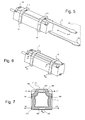
- FIG. 5 is a diagram illustrating an example assembly process for inserting the expanding mechanism 23 in the damping bodies 11 and 12.
- Damping bodies 11 and 12 can be made form rubber or viscoelastic material.
- the first damping body 11 can comprise two flat holes configured to accommodate spikes 21 and 22. One of these flat holes 11 is illustrated in figure 5 , where the other is not shown because it is positioned underneath casing 14.
- the second damping body 12 comprises two flat holes, one hole 121 illustrated in top of casing 14 and another not illustrated underneath casing 14.
- a protrusion 148 on the casing 14 can also be included to act as a spike stop.
- Flat holes 111 and 121, and the corresponding holes underneath casing 14, can be substantially rectangular, with a width equal to the width of the constant-width section 203 and a height equal or less to the thickness of each spike 21 and 22.
- Spikes 21 and 22 can be inserted in the axial direction simply by pushing them into the flat holes in the direction of arrow A10.
- the bottom recess 147 facilitates insertion of, e.g., spike 22, by leaving a sufficient space between the casing 14 and the headrail 3 to accommodate the spike 22.
- first expanded section 202 of the first spike 21 When the first expanded section 202 of the first spike 21 enters the flat hole 121, it induces expansion of the rubber or viscoelastic material of the second damping body 12. If the pushing action is maintained, then the first expanded section 202 totally passes through the second damping body 12 and then the constant-width section 203 should slide easily through the flat hole 121 due to its reduced width.
- the pushing action is ended before the spike 21 is totally inserted, namely when the tapered opening section 201 enters the first flat hole 111. In that situation, no stress or strain is applied to the two damping bodies 11 and 12. The same will be done for the second spike 22.
- the actuator 10 set is complete and remains easy to manipulate when inserting in headrail 3. Even when included in the headrail 3, it can be moved easily in the axial direction.
- this position i.e., not totally inserted, then this is referred as the "rest position" of the expansion mechanism 23, as depicted in figure 13 .
- the actuators 10 can be provided to the installer in the rest position. The first pushing action is then made at the factory.
- Figure 13 shows how the expansion mechanism 23 can be maintained in the actuator 10 in the rest position, where the damping bodies 11 and 12 are shown as transparent.
- the opening section 201 has been inserted in the flat hole 111 of the first damping body 11. As the size of each hole is just equal to the larger size of the opening section, the friction of the spike with both holes, and mainly with the second flat hole 121, can be enough to maintain the spike in its rest position, even when the actuator 10 is manipulated rapidly by the installer.
- FIG. 6 illustrating the actuator 10 in a mounted position.
- a second pushing action in the A10 direction results in each expanded section 202 and 204 coming to rest within the respective flat hole, e.g., flat holes 111 and 121 for spike 21.
- the mechanical stop 205 and the spike stop 148 prevent further pushing.
- each upper part of the damping bodies 11 and 12 are expanded laterally as shown by arrows A1, and each lower part of the damping bodies 11 and 12 is also expanded laterally as shown by arrows A2. This is referred as the "clamped position" or "mounted position" of the expansion mechanism 23.
- FIG. 7 is a cross-section view actuator 10, when inserted in the headrail 3.
- the casing 14 and inner parts of the actuator 10 are not shown for simplicity.
- Generic references are used, starting with numbers 1 and 0: for instance an upper flat hole 101 will become 111 if referring to the first damping body 11 and will become 121 if referring to the second damping body 12. Same for a lower flat hole 102, leading to 112 and 122.
- the damping body 11,12 includes an outer shape 103 adapted to fit within the headrail profile and includes an inner shape 104 adapted to fit within a grove included in the actuator casing 14.
- a dashed line shows the external profile 104 of the rest of the actuator casing 14 not including the grooves.
- An advantage of groves is to maintain each damping body in a given axial position.
- a first lateral expansion area 106 is in the horizontal extension of the upper flat hole 101 and causes the damping body 11,12 to press against the top end 32a of the headrail 3 when the expanded section 202,204 of the spike 21 is inserted in the upper flat hole (arrow A1). The same thing happens on the right side (arrow A'1).
- a second lateral expansion area 107 is in the horizontal extension of the lower flat hole 102 and causes the damping body 11,12 to press against the lower left lateral surface 32b of the headrail when the expanded section 202,204 of the spike 22 is inserted in the lower flat hole 102 (arrow A2). The same exists on the right side (arrow A'2).
- the actuator 10 is efficiently clamped in the headrail 3 by the second lateral expansion 107 areas as soon as the spike 22 is fully inserted.
- a strain and/or stress can also be created in a bottom expansion area 108 if the thickness of the spike 22 is greater than the flat hole height.
- Figure 8 is a cross-sectional view of another example type of damping body 41,42 that can be used in conjunction with another type of actuator in accordance with another embodiment.
- the actuator is not shown as in figure 7 .
- the damping body 41,42 is shown installed in headrail 3.
- damping body 41,42 includes upper and lower cylindrical holes 401 and 402 respectively.
- a first lateral expansion area 406 is in the horizontal extension of the upper holes 401
- a second lateral expansion area 407 is in the horizontal extension of the lower holes 402.
- Lateral expansions are shown by arrows A1, A'1 and A2, A'2.
- Reference 403 refers to the outer shape of the damping body 41,42.
- the inner shape 404 fits within a cylindrical grove belonging to a cylindrical casing 44 of an actuator (see figure 9 ).
- the dashed line 405 shows the position of an external cylindrical casing of the actuator 44 outside the cylindrical grooves.
- Figure 9 shows a cross section, along the line Y-Y' and perpendicularly to the plane of figure 8 , of actuator 40, including the damping bodies 41 and 42 and an expanding mechanism 43.
- the actuator 40 also includes a cylindrical casing 44 with groves (not shown) where the damping bodies 41 and 42 are inserted.
- the expanding mechanism 43 is provided to interface with each of holes 401 and 402.
- the expanding mechanism 43 includes a bolt 46 and a nut 47.
- a cylindrical hollow brace 45 or a hollow spacer or a hollow space bar can be inserted between the two damping bodies 41 and 42 and can be traversed by the bolt 46.
- a link 48 allows blocking the rotation of the nut 47 when the bolt 46 is turned.
- Such a bolt 46 and nut 47combination can be provided for each hole 401 and 402.
- the bolt-nut assembly is designed to have a sufficient expansion with only a quarter of turn of the bolt 46.
- tapered ends of the hollow brace 45 can improve significantly the lateral expansion of the damping bodies 41 and 42.
- Figure 10 shows a partial view of the second embodiment, including an alternative construction 41' of the damping body 41.
- This alternative construction uses the damping body 41 sandwiched between a first plate 411' and a second plate 412'.
- the fist plate includes a circular hole 413' larger than the bolt diameter in front of each hole 401-402.
- the second plate 412' includes a threaded hole 414' in which the bolt will be engaged.
- a unique hollow brace 45' (not shown) is preferably used, surrounding the cylindrical casing 44 of the actuator 40 and maintaining the distance between the two damping bodies 41' and 42'.
- Figure 11 shows a partial view of still another example actuator 50 including damping bodies 51 and 52 and expanding mechanism 53 in accordance with another embodiment.
- the damping bodies 51 and 52 in this example are surrounding the casing 54 of the actuator 50 and are for instance larger than in the previous examples. They can include a large hole 501 in the vicinity of each top end 32a and 34a of the headrail 3. A same large hole can exist in the lower part in the vicinity of each lower lateral surface 32b and 34b.
- the expanding mechanism 53 can have an axial symmetry and can include an ovoid body 531, the diameter of which can be larger than the large hole 501, linked to a long string 532 on one end and to a short string 534 on the other end.
- a first end-limit 533 and a second end-limit 535 terminate each string respectively.
- Figure 11 shows the expansion mechanism in a rest position. Clamping of the actuator in the headrail is simply realized by pulling the long string 532. Then, a lateral expansion of the damping body 51,52 is created by the expansion mechanism 53. The clamped position is preferably reached when the ovoid body 531 is centred in the large hole 501. Unclamping of the actuator 50 is achieved by pulling the short string 534.
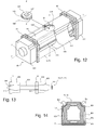
- Figure 12 is a diagram illustrating another example actuator 60, including further example damping bodies 61 and 62 and another example expanding mechanism 63 in accordance with one embodiment.
- the actuator 60 includes a motor (not shown) and gear (not shown) with a cylindrical housing 64, a first rectangular blocking section 641 at a first end and a second rectangular blocking section 642 at the second end.
- a shaft output (not shown) is at the first end and is connected to the shaft 7.
- expanding mechanism 63 includes two outer casings and a rotating unit.
- the first damping body 61 is inserted between the first blocking body 641 and a first outer casing 631 (shown with dotted lines).
- the second damping body is inserted between the second blocking body and a second outer casing 632.
- Each outer casing has a rectangular profile, includes an axial grove 633 and is movable axially, guided by an axial protrusion 643 on each side of the cylindrical housing 64.
- the rotating unit 634 that rotates around a vertical axis Z-Z' is located in the central part of the actuator 60.
- the rotating unit 634 is shown in its rest orientation. It includes a disk 635 coaxial with Z-Z' superposed and mechanically linked with an eccentric body 636 larger than the disk.
- a square hole 637 allow to insert a tool to create a rotation around the Z-Z' axis.
- the rotating unit is maintained downwards by the motor housing 64 and upwards by a circular collar 638 belonging to the upper face of each outer casing. Under this collar, an elliptic track 639 machined in the outer casing has substantially the same elliptic shape than the eccentric 636, the larger axis being perpendicular to X-X' and Z-Z'.
- the eccentric 636 is in contact with the elliptic track.
- two small notches (not shown) disposed axially in the elliptic tracks give a stable position of the rotating unit (clamped position) when it is turned by 90° from the rest orientation (rest position).
- Intermediary accessory 300 has an inner shape 301 that fits with the outer shape 103 of, e.g., the damping means 11 or 12.
- the outer shape 302 of the intermediary accessory fits with the profile of headrail 3.
- the intermediary accessory can be made of a rigid plastic body 303 and can contain articulations 304 that allow a lateral expansion when the damping body extends laterally.
- the intermediary accessory can improve the sliding ability of the actuator in the headrail before it is clamped.
- a tool that can impart an axial action can be used for going from a rest position to a clamped position and conversely. This can be useful when the actuator is a motor to be dismounted and mounted on a side end of the headrail, as shown in figure 1 , e.g., during a maintenance operation. For instance, the extraction hole 206 on each spike allows inserting a tool to pull back the spike in its rest position.
Landscapes
- Engineering & Computer Science (AREA)
- Structural Engineering (AREA)
- Power Engineering (AREA)
- Architecture (AREA)
- Civil Engineering (AREA)
- Operating, Guiding And Securing Of Roll- Type Closing Members (AREA)
- Blinds (AREA)
- Curtains And Furnishings For Windows Or Doors (AREA)
Description
- The embodiments described herein generally relate to motorized window coverings, and more particular to reducing noise and vibrations created by a motorized window covering.
- A problem with conventional motorized window coverings is transmission of vibrations induced in the motor, in particular "solidborne" transmission of vibrations. These vibrations can create operational problems as well as unacceptable noise levels. Typically, it is very important to reduce the noise emitted by such devices. For example, the emitted noise should be below 50 decibels.
- The motor and other mechanical accessories of such motorized window coverings are usually included in a headrail, made of a metal sheet, such as steel or aluminium. Such a conventional headrail is often neither closed nor rigid. The transmission of vibrations from the motor to the headrail may activate vibration resonant modes of the headrail or at least will allow the radiation of vibrations upon the whole headrail surface with a strong amplification effect.
- Consequently, damping accessories that provide viscoelastic suspension and/or viscoelastic transmission are often used with such devices to minimize the solidborne transmission. For example, the Australian patent application
2008100304 - The
US patent application 2009/0000749 discloses a drive unit for a Venetian blind or the like. The drive unit includes an electric motor, one or two gear units, and two output shafts. The motor casing is made with components, isolating coating, and damping plugs that provide acoustical damping and uncoupling and that are shaped to be insertable into the headrail. -
EP 1 321 623 discloses a mounting apparatus for an electromotor installed in a U-shaped headrail including flexible vibration-damping bodies attached on the ends of mounting feet provided on the electromotor. A U-shaped clip is attached around the headrail between the two mounting feet and includes a clamping device that allows exerting a pressure on the electromotor. - It is then common to include vibration-damping bodies around a drive unit before inserting it in a window covering headrail. It should be noted that a conventional horizontal headrail is usually U-shaped. Accordingly, the drive unit, with vibration damping bodies, may be inserted in the headrail either laterally or vertically.
- A problem with conventional damping suspension devices, such as those disclosed in the patents and patent applications discussed above is that they require a certain amount of stress or strain between the drive unit and the headrail to operate properly. In other words, if the damping devices are too lose when the drive unit is installed in the headrail, then they cannot provide adequate dampening; however, when the damping devices are sized to achieve the necessary stress or strain, then a certain amount of friction is created that makes it difficult to move the drive unit inside the headrail. On the other hand, if the friction is reduced, then the damping devices may not adequately dampen vibrations, the drive unit may not be adequately stabilized within the headrail, or both.
- For example, in
AU 2008100304 - In
US 2009/0000749 , a provision is made for leaving room between the isolating coatings and the headrail and the same considerations apply to damping plugs. But how the drive unit is kept tight into the headrail is not addressed, nor is it clear from the disclosure. - In
EP 1 321 623 a means to secure the clip by exerting a pressure on the motor with an appropriate tool is disclosed. The clip tightens the headrail and compresses the vibration-damping bodies to provide the necessary stress or strain while allowing the drive unit to move within the headrail when the external clip is not in place. But the aesthetic result when the clip is installed is poor. - An actuator for a powered window covering system that reduces vibrations and allows easy positioning of an actuator within a headrail is disclosed in claim 1.
- The actuator comprises a damping body configured to reduce vibrations when the actuator is operating i.e. a damping body configured to reduce the transmission of vibrations between the actuator and the headrail, and an expanding mechanism configured to expand the damping body against the headrail. The damping body is configured to reduce the transmission of vibrations between the actuator and the headrail and especially to reduce the transmission of vibrations from the actuator to the headrail when the actuator is operating.
- The expanding mechanism can comprise one or more spikes, a bolt and nut combination, an ovoid body, or a rotating body. The damping body can comprise holes or other receiving mechanisms for receiving the expanding mechanism.
- The expanding mechanism has a rest position in which the expanding mechanism is coupled with the damping body but is not acting to expand the damping body against the headrail.
- According to another aspect, a powered window covering system comprises a headrail; and an actuator to be inserted in the headrail, the actuator comprising a damping body configured to reduce vibrations when the actuator is operating, and an expanding mechanism configured to expand the damping body against the headrail.
- A further aspect, however, not belonging to the present invention, relates to a damping device to be inserted between a headrail of a window covering and an actuator, the damping device comprising a damping body configured to reduce vibrations when the actuator is operating i.e. a damping body configured to reduce the transmission of vibrations between the actuator and the headrail, and an expanding mechanism configured to expand the damping body against the headrail. The damping body is configured to reduce the transmission of vibrations between the actuator and the headrail and especially to reduce the transmission of vibrations from the actuator to the headrail when the actuator is operating.
- These and other features, aspects, and embodiments are described below in the section entitled "Detailed Description."
- Features, aspects, and embodiments are described in conjunction with the attached drawings, in which:
-
Figure 1 is a schematic diagram illustrating an example powered window covering according to one embodiment. -
Figure 2 shows a cross section of a headrail included in the powered window covering offigure 1 . -
Figure 3 is a diagram illustrating an example embodiment of an actuator and damping bodies included in the powered window covering offigure 1 and that can be position within the headrail offigure 2 in accordance with one embodiment. -
Figure 4 is a diagram illustrating an example expanding mechanism that can be used in conjunction with the damping bodies offigure 3 in accordance with one embodiment. -
Figure 5 is a diagram illustrating an example assembly process for inserting expanding mechanism offigure 4 into the damping bodies offigure 3 in accordance with one embodiment. -
Figure 6 is a diagram illustrating the expanding mechanism offigure 4 in the mounted position. -
Figure 7 is a cross-section view of the actuator offigure 3 inserted in the headrail offigure 2 . -
Figure 8 is a cross-section view of the actuator offigure 3 inserted in the headrail offigure 2 , wherein the actuator includes a damping body configured in accordance with another example embodiment. -
Figure 9 is a cross-section view of another example actuator, including the damping body offigure 8 and another example expanding means, in accordance with another embodiment. -
Figure 10 shows a partial view of the actuator offigure 9 , including another example damping body. -
Figure 11 is a diagram illustrating another example actuator, including another example damping body and another example expanding means, in accordance with one embodiment. -
Figure 12 is a diagram illustrating another example actuator, including another example damping body and another example expanding means, in accordance with one embodiment. -
Figure 13 is a diagram illustrating the "rest position" of expanding mechanism offigure 4 . -
Figure 14 is a diagram illustrating a cross-section of an actuator that includes an intermediary accessory and a damping means inserted in a headrail in accordance with another example embodiment. -
Figure 1 is a schematic diagram illustrating an example powered window covering 1 according to one embodiment. In the example offigure 1 , the powered window covering includes amobile screen 2, e.g., a Venetian blind, a pleated shade, a Roman shade, etc., and aheadrail 3. The top part of thescreen 2 is connected to theheadrail 3 byfixed links 4, and the bottom part of thescreen 2 is connected to aload bar 5, which ensures a given tension upon thescreen 2. - The
headrail 3 can be configured to house several actuators such as a motor 6 and windingdevices 8, each connected to arotating shaft 7. The axis X-X' of theshaft 7 is normally horizontal. Infigure 1 , the motor 6 is at one end of theheadrail 3 but it can alternatively be positioned at the other end or in a central position, e.g., with two outputs connected to two shafts. An advantage of having the motor at one end of the headrail is an easier maintenance or cabling. It may also facilitate clamping the motor as seen hereafter. - The
load bar 5 can be attached tocords 9, which are linked to windingdevices 8 throughholes 3a theheadrail 3. Thecords 9 can be wound or unwound by windingdevices 8 according to the direction of rotation of theshaft 7, enabling an upward or downward motion of theload bar 5. -
Grey areas 3b infigure 1 are the contact areas where motor 6 and windingdevices 8 contact theheadrail 3. It can be preferable forcontact areas 3b to be as small as possible in order to reduce noise and vibration; however,contact areas 3b must be sufficient to maintain the outward pressure needed to hold the motor 6 and windingdevice 8 in place. Accordingly, while the size ofarea 3b can change based on the needs of a particular implementation, it should be sufficient to maintain the outward pressure needed and to prevent vibration as described below. - Vibrations of the motor 6 can excite the
headrail 3 either directly or indirectly. Indirect excitation happens through a solid path from the motor 6 to theheadrail 3 made of theshaft 7 and the windingdevice 8. This is why, for example, theshaft 7 is often linked to the output of the motor 6 by uncoupling means 7a. It will be understood that such uncoupling means 7a can act to reduce vibrations along the solid path described above; however, the efficiency of uncoupling means 7a is not always enough to sufficiently reduce vibrations along the solid, indirect path. - Accordingly, the damping devices described below can be used to prevent or further prevent such vibration. The damping devices described herein can be used in conjunction with both the motor 6, winding
devices 8, or both, and can be used in conjunction with many variations of such motors or winding devices; however, for cost and simplicity, it can be preferable to use the damping devices with only the motor 6, with or without uncoupling means 7a on theshaft 7. -
Figure 2 shows a cross section of theheadrail 3 in a vertical plane, the headrail axis being parallel to the shaft axis and horizontal. The direction of view is indicated onfigure 1 with a horizontal arrow labelled A0. - The
headrail 3 can be made from a folded metal sheet and can exhibit a U-shaped profile, opened on thetop surface 31, as seen infigure 2 . Theheadrail 3 can comprise a leftlateral surface 32 and a right lateral surface 34 linked to abottom surface 33. The top ends, respectively 32a and 34a, oflateral surfaces 32 and 34 can be bent inwards as illustrated. Thelower portions lateral surfaces 32 and 34 respectively are located near thebottom surface 33 and can exhibit a high rigidity. Alternatively, mainly in the case of "Roman shades" window coverings, the U shape profile ofheadrail 3 can be rotated 180 degrees such that it opens downward. -
Actuators 6 and 8 can then be placed within theheadrail 3.Figure 3 is a diagram illustrating anexample actuator 10 that can be included in theheadrail 3 in accordance with one embodiment. Theactuator 10 can, e.g., be the motor 6, with a shaft output (not visible) connected to theshaft 7. Alternatively, it can be a windingdevice 8 and can be connected to two shafts or connected to a traversing shaft depending on the implementation. - The
actuator 10 can include a first dampingbody 11 and a second dampingbody 12 surrounding arectangular casing 14, the length of which is oriented in the X-X' direction. Thecasing 14 can comprise atop face 141, aleft face 142, a bottom face 143 (hidden) and a right face (hidden). Thecasing 14 can also include a front face 145 (hidden) and arear face 146. Thefront face 145, or both thefront face 145 and therear face 146 can include a shaft output to accommodateshaft 7. Abottom recess 147 on therear face 146 and axially on thebottom face 143 can provide a larger space between thecasing 14 and theheadrail 3 in the recessed area. -
Casing 14 and dampingbodies actuator 10 can be easily inserted and positioned withinheadrail 3. Once in place, an expanding mechanism can be inserted into dampingbodies headrail 3 to holdactuator 10 in place. -
Figure 4 is a diagram illustrating an example expanding mechanism 23 comprising twosimilar spikes bodies spike spike tapered opening section 201, a first expandedsection 202, a constant-width section 203, a second expandedsection 204, amechanical stop 205, and an extractinghole 206. The length of eachspike actuator 10 in the axial direction. The distance between the expanded sections should be equal to the distance between the dampingbodies bodies spikes opening section 201 at its widest point can be equal to the width of theconstant width section 203. -
Figure 5 is a diagram illustrating an example assembly process for inserting the expanding mechanism 23 in the dampingbodies bodies body 11 can comprise two flat holes configured to accommodatespikes flat holes 11 is illustrated infigure 5 , where the other is not shown because it is positioned underneathcasing 14. Similarly, the second dampingbody 12 comprises two flat holes, onehole 121 illustrated in top of casing 14 and another not illustrated underneathcasing 14. Aprotrusion 148 on thecasing 14 can also be included to act as a spike stop. -
Flat holes width section 203 and a height equal or less to the thickness of eachspike Spikes bottom recess 147 facilitates insertion of, e.g., spike 22, by leaving a sufficient space between thecasing 14 and theheadrail 3 to accommodate thespike 22. - When the first expanded
section 202 of thefirst spike 21 enters theflat hole 121, it induces expansion of the rubber or viscoelastic material of the second dampingbody 12. If the pushing action is maintained, then the first expandedsection 202 totally passes through the second dampingbody 12 and then the constant-width section 203 should slide easily through theflat hole 121 due to its reduced width. - In certain embodiments, the pushing action is ended before the
spike 21 is totally inserted, namely when thetapered opening section 201 enters the firstflat hole 111. In that situation, no stress or strain is applied to the two dampingbodies second spike 22. - Then the actuator 10 set is complete and remains easy to manipulate when inserting in
headrail 3. Even when included in theheadrail 3, it can be moved easily in the axial direction. When the spike are in this position, i.e., not totally inserted, then this is referred as the "rest position" of the expansion mechanism 23, as depicted infigure 13 . - It can be preferable for the
actuators 10 to be provided to the installer in the rest position. The first pushing action is then made at the factory. -
Figure 13 shows how the expansion mechanism 23 can be maintained in theactuator 10 in the rest position, where the dampingbodies opening section 201 has been inserted in theflat hole 111 of the first dampingbody 11. As the size of each hole is just equal to the larger size of the opening section, the friction of the spike with both holes, and mainly with the secondflat hole 121, can be enough to maintain the spike in its rest position, even when theactuator 10 is manipulated rapidly by the installer. -
Figure 6 illustrating theactuator 10 in a mounted position. A second pushing action in the A10 direction results in each expandedsection flat holes spike 21. Themechanical stop 205 and thespike stop 148 prevent further pushing. Then, each upper part of the dampingbodies bodies -
Figure 7 is across-section view actuator 10, when inserted in theheadrail 3. Thecasing 14 and inner parts of theactuator 10 are not shown for simplicity. Generic references are used, starting with numbers 1 and 0: for instance an upperflat hole 101 will become 111 if referring to the first dampingbody 11 and will become 121 if referring to the second dampingbody 12. Same for a lowerflat hole 102, leading to 112 and 122. The dampingbody outer shape 103 adapted to fit within the headrail profile and includes aninner shape 104 adapted to fit within a grove included in theactuator casing 14. A dashed line shows theexternal profile 104 of the rest of theactuator casing 14 not including the grooves. An advantage of groves is to maintain each damping body in a given axial position. - A first
lateral expansion area 106 is in the horizontal extension of the upperflat hole 101 and causes the dampingbody top end 32a of theheadrail 3 when the expanded section 202,204 of thespike 21 is inserted in the upper flat hole (arrow A1). The same thing happens on the right side (arrow A'1). - A second
lateral expansion area 107 is in the horizontal extension of the lowerflat hole 102 and causes the dampingbody lateral surface 32b of the headrail when the expanded section 202,204 of thespike 22 is inserted in the lower flat hole 102 (arrow A2). The same exists on the right side (arrow A'2). - As the
lower parts headrail 3 are rigid, theactuator 10 is efficiently clamped in theheadrail 3 by the secondlateral expansion 107 areas as soon as thespike 22 is fully inserted. - As shown by the arrow A3, a strain and/or stress can also be created in a
bottom expansion area 108 if the thickness of thespike 22 is greater than the flat hole height. -
Figure 8 is a cross-sectional view of another example type of dampingbody figure 8 , the actuator is not shown as infigure 7 . Further, the dampingbody headrail 3. - In the embodiment of
figure 8 , dampingbody cylindrical holes body lateral expansion area 406 is in the horizontal extension of theupper holes 401, and a secondlateral expansion area 407 is in the horizontal extension of thelower holes 402. Lateral expansions are shown by arrows A1, A'1 and A2, A'2.Reference 403 refers to the outer shape of the dampingbody inner shape 404 fits within a cylindrical grove belonging to acylindrical casing 44 of an actuator (seefigure 9 ). The dashedline 405 shows the position of an external cylindrical casing of theactuator 44 outside the cylindrical grooves. -
Figure 9 shows a cross section, along the line Y-Y' and perpendicularly to the plane offigure 8 , ofactuator 40, including the dampingbodies mechanism 43. Theactuator 40 also includes acylindrical casing 44 with groves (not shown) where the dampingbodies mechanism 43 is provided to interface with each ofholes - The expanding
mechanism 43 includes abolt 46 and anut 47. A cylindricalhollow brace 45 or a hollow spacer or a hollow space bar can be inserted between the two dampingbodies bolt 46. Alink 48 allows blocking the rotation of thenut 47 when thebolt 46 is turned. Such abolt 46 and nut 47combination can be provided for eachhole - In
figure 9 , the rest position ofexpansion mechanism 43 is shown. It should be noted that no stress or strain is applied by theexpansion mechanism 43. - When the
bolt 46 is tightened, then, a lateral expansion of the dampingbodies expansion mechanism 43 is in its clamped position. - Preferably, the bolt-nut assembly is designed to have a sufficient expansion with only a quarter of turn of the
bolt 46. In certain embodiments, tapered ends of thehollow brace 45 can improve significantly the lateral expansion of the dampingbodies -
Figure 10 shows a partial view of the second embodiment, including an alternative construction 41' of the dampingbody 41. This alternative construction uses the dampingbody 41 sandwiched between a first plate 411' and a second plate 412'. The fist plate includes a circular hole 413' larger than the bolt diameter in front of each hole 401-402. The second plate 412' includes a threaded hole 414' in which the bolt will be engaged. - An alternative construction 42' of the damping
body 42 will be similar except that all holes have a larger diameter than the bolt. - When using this alternative construction, a unique hollow brace 45' (not shown) is preferably used, surrounding the
cylindrical casing 44 of theactuator 40 and maintaining the distance between the two damping bodies 41' and 42'. -
Figure 11 shows a partial view of still anotherexample actuator 50 including damping bodies 51 and 52 and expandingmechanism 53 in accordance with another embodiment. - The damping bodies 51 and 52 in this example are surrounding the
casing 54 of theactuator 50 and are for instance larger than in the previous examples. They can include alarge hole 501 in the vicinity of eachtop end headrail 3. A same large hole can exist in the lower part in the vicinity of each lowerlateral surface mechanism 53 can have an axial symmetry and can include anovoid body 531, the diameter of which can be larger than thelarge hole 501, linked to along string 532 on one end and to ashort string 534 on the other end. A first end-limit 533 and a second end-limit 535 terminate each string respectively. -
Figure 11 shows the expansion mechanism in a rest position. Clamping of the actuator in the headrail is simply realized by pulling thelong string 532. Then, a lateral expansion of the damping body 51,52 is created by theexpansion mechanism 53. The clamped position is preferably reached when theovoid body 531 is centred in thelarge hole 501. Unclamping of theactuator 50 is achieved by pulling theshort string 534. -
Figure 12 is a diagram illustrating anotherexample actuator 60, including furtherexample damping bodies example expanding mechanism 63 in accordance with one embodiment. Theactuator 60 includes a motor (not shown) and gear (not shown) with acylindrical housing 64, a firstrectangular blocking section 641 at a first end and a secondrectangular blocking section 642 at the second end. A shaft output (not shown) is at the first end and is connected to theshaft 7. - In this example embodiment, expanding
mechanism 63 includes two outer casings and a rotating unit. The first dampingbody 61 is inserted between thefirst blocking body 641 and a first outer casing 631 (shown with dotted lines). The second damping body is inserted between the second blocking body and a secondouter casing 632. Each outer casing has a rectangular profile, includes anaxial grove 633 and is movable axially, guided by anaxial protrusion 643 on each side of thecylindrical housing 64. Therotating unit 634 that rotates around a vertical axis Z-Z' is located in the central part of theactuator 60. Therotating unit 634 is shown in its rest orientation. It includes adisk 635 coaxial with Z-Z' superposed and mechanically linked with aneccentric body 636 larger than the disk. Asquare hole 637 allow to insert a tool to create a rotation around the Z-Z' axis. - The rotating unit is maintained downwards by the
motor housing 64 and upwards by acircular collar 638 belonging to the upper face of each outer casing. Under this collar, anelliptic track 639 machined in the outer casing has substantially the same elliptic shape than the eccentric 636, the larger axis being perpendicular to X-X' and Z-Z'. The eccentric 636 is in contact with the elliptic track. When the rotating unit rotates, bothouter casings - Preferably, two small notches (not shown) disposed axially in the elliptic tracks give a stable position of the rotating unit (clamped position) when it is turned by 90° from the rest orientation (rest position).
- Accordingly, various damping bodies can be used depending on the kind of headrail. Only their outer shape has to change. Due to the number of different shapes of headrail, inserting an intermediary accessory between the damping body and the headrail can also be used as a mixed approach, as depicted by
figure 14 .Intermediary accessory 300 has aninner shape 301 that fits with theouter shape 103 of, e.g., the damping means 11 or 12. Theouter shape 302 of the intermediary accessory fits with the profile ofheadrail 3. When using such intermediary accessories, it is preferred to manufacture a unique-type damping body for all uses and a plurality of accessories fitting both with this unique-type damping body and with the different shapes of headrail. - The intermediary accessory can be made of a rigid
plastic body 303 and can containarticulations 304 that allow a lateral expansion when the damping body extends laterally. The intermediary accessory can improve the sliding ability of the actuator in the headrail before it is clamped. - A tool that can impart an axial action can be used for going from a rest position to a clamped position and conversely. This can be useful when the actuator is a motor to be dismounted and mounted on a side end of the headrail, as shown in
figure 1 , e.g., during a maintenance operation. For instance, theextraction hole 206 on each spike allows inserting a tool to pull back the spike in its rest position. - While certain embodiments have been described above, it will be understood that the embodiments described are by way of example only. Accordingly, the systems and methods described herein should not be limited based on the described embodiments. Rather, the systems and methods described herein should only be limited in light of the claims that follow when taken in conjunction with the above description and accompanying drawings.
Claims (11)
- An actuator (6, 8; 10; 40; 50; 60) to be inserted in a headrail (3) of a window covering (1), the actuator comprising:- a damping body (11, 12; 41, 42; 41', 42'; 51, 52; 61, 62) configured to reduce vibrations when the actuator is operating; characterized in that the actuator further comprises- an expanding mechanism (23; 43; 53; 63) configured to expand the damping body against the headrail;wherein :- the expanding mechanism comprises a spike (21) and the damping body comprises a hole (111, 121; 101, 102) configured to receive the spike, or- the expanding mechanism comprises a plurality of spikes and the damping body comprises a plurality of holes configured to receive the spikes, the spike or the spikes comprising an expanded section (202, 204) of a width that is wider than a width of the hole ; orwherein :the expanding mechanism (53) comprises an ovoid body (531) and the damping body (51, 52) comprises a hole (501) configured to receive the ovoid body (531),the hole having a diameter that is less than the maximum diameter of the ovoid body ; orwherein :the expanding mechanism (63) comprises a rotating unit (634), the actuator further comprising a first outer casing (631), a second outer casing (632), and the rotating unit comprising a disk (635) coaxially mounted with an eccentric body (636), andthe outer casings being pushed away against each damping body (61, 62) when the eccentric body rotates ; orwherein :the actuator comprises an intermediary accessory (300) to be positioned between the headrail and damping body, the intermediary accessory (300) comprising articulations (304) that allow a lateral expansion when the damping body extends laterally.
- The actuator of claim 1, further comprising a plurality of damping bodies, and wherein the expanding mechanism is configured to expand each of the plurality of damping bodies against the headrail.
- The actuator of one of claims 1 to 2, wherein the damping body comprises at least one lateral expansion area (106, 107; 406, 407), for example at least an upper lateral expansion area (106; 406) and/or at least a lower lateral expansion area (107; 407), in which the damping body is expanded against the headrail.
- The actuator of claim 3, wherein the damping body includes an upper lateral expansion area and a lower lateral expansion area on each side of the damping body in which the damping body is expanded against the headrail.
- The actuator of one of claims 1 to 4, wherein the damping body is inserted and axially maintained in a grove of the actuator.
- The actuator (40) of one of claims 1 to 5, wherein the expanding mechanism (43) comprises a bolt (46) and nut (47) combination, and wherein the damping body (41, 42; 41', 42') comprises a hole (401, 402) configured to receive the bolt.
- The actuator of claim 6, further comprising two damping bodies, wherein the expanding mechanism is configured to expand each damping body against the headrail, and wherein the bolt is inserted through a hole in each damping body and the nut is tightened on an end of the bolt in order to expand the damping bodies.
- The actuator of claim 7, wherein the expanding means further comprises a hollow brace (45) positioned between the damping bodies and is configured to receive the bolt.
- The actuator of one of claims 1 to 8, wherein the expanding mechanism has a rest position in which the expanding mechanism is coupled with the damping body but is not acting to expand the damping body against the headrail.
- A powered window covering system (1), comprising:a headrail (3); andan actuator (10; 40; 50; 60) according to one of claims 1 to 9.
- The powered window covering system of claim 10, wherein the headrail has a U-shaped cross section.
Applications Claiming Priority (2)
| Application Number | Priority Date | Filing Date | Title |
|---|---|---|---|
| US12/496,304 US8141614B2 (en) | 2009-07-01 | 2009-07-01 | Expanding coupling means for powered window covering |
| PCT/EP2010/059357 WO2011000908A1 (en) | 2009-07-01 | 2010-07-01 | Expandable and damping motor mounting in a window covering headrail |
Publications (2)
| Publication Number | Publication Date |
|---|---|
| EP2449201A1 EP2449201A1 (en) | 2012-05-09 |
| EP2449201B1 true EP2449201B1 (en) | 2016-10-26 |
Family
ID=42734105
Family Applications (1)
| Application Number | Title | Priority Date | Filing Date |
|---|---|---|---|
| EP10727744.4A Not-in-force EP2449201B1 (en) | 2009-07-01 | 2010-07-01 | Expandable and damping motor mounting in a window covering headrail |
Country Status (4)
| Country | Link |
|---|---|
| US (1) | US8141614B2 (en) |
| EP (1) | EP2449201B1 (en) |
| CN (1) | CN102472079B (en) |
| WO (1) | WO2011000908A1 (en) |
Families Citing this family (7)
| Publication number | Priority date | Publication date | Assignee | Title |
|---|---|---|---|---|
| JP6585351B2 (en) * | 2015-01-30 | 2019-10-02 | 立川ブラインド工業株式会社 | Motor mounting structure for solar shading device |
| US11072976B2 (en) * | 2017-02-06 | 2021-07-27 | Hunter Douglas, Inc. | Methods and apparatus to reduce noise in motor assemblies |
| KR102530258B1 (en) | 2017-07-13 | 2023-05-08 | 셀링크 코포레이션 | Interconnect circuit method and apparatus |
| CA3019986A1 (en) | 2017-10-09 | 2019-04-09 | Hunter Douglas Inc. | Rail assemblies for motorized architectural coverings and related methods |
| CN108258839B (en) * | 2017-12-27 | 2019-09-20 | 再兴电子(深圳)有限公司 | A kind of actuation means |
| US20200068292A1 (en) | 2018-08-21 | 2020-02-27 | Gopro, Inc. | Audio Enhancements In Devices Using Motors |
| BE1029700B1 (en) * | 2021-08-19 | 2023-03-20 | Copahome Nv | MOTOR BRACKET FOR MOUNTING A DRIVE DEVICE IN A SHIELD DEVICE |
Family Cites Families (23)
| Publication number | Priority date | Publication date | Assignee | Title |
|---|---|---|---|---|
| US2670532A (en) * | 1949-09-23 | 1954-03-02 | Lorentzen Hardware Mfg Corp | Apparatus useful in assembling venetian blind bars |
| DE3611857A1 (en) * | 1986-04-09 | 1987-10-22 | Stoever Adolf Bautex Kg | SPACER FOR A VERTICAL BLINDS |
| US4825983A (en) * | 1987-03-14 | 1989-05-02 | Motoyasu Nakanishi | Inertia damper |
| DE3825062A1 (en) * | 1988-07-23 | 1990-01-25 | Freudenberg Carl Fa | Torsional vibration damper |
| CA1302231C (en) * | 1989-02-17 | 1992-06-02 | David P. Rozon | Sliding link system for vertical blinds |
| US5071137A (en) * | 1990-12-27 | 1991-12-10 | Mccloud Calvin E | Table soccer game bumper structure |
| DE29514004U1 (en) * | 1995-08-31 | 1995-11-09 | Fiedler, Kurt, 65468 Trebur | Hydraulically damped bearing |
| US5735257A (en) * | 1996-02-02 | 1998-04-07 | Hoyt Usa | Multi-chamber stabilizer for archery bows |
| US6263945B1 (en) * | 2000-01-19 | 2001-07-24 | Ming Nien | Venetian blinds |
| JP2001280420A (en) * | 2000-03-30 | 2001-10-10 | Tokai Rubber Ind Ltd | Cylindrical dynamic damper and method of manufacturing the same |
| US6497267B1 (en) * | 2000-04-07 | 2002-12-24 | Lutron Electronics Co., Inc. | Motorized window shade with ultraquiet motor drive and ESD protection |
| JP2002098193A (en) * | 2000-09-25 | 2002-04-05 | Tokai Rubber Ind Ltd | Cylindrical dynamic damper |
| DE10142434A1 (en) * | 2001-08-31 | 2003-04-03 | Kaba Gallenschuetz Gmbh | Drive and locking unit |
| DE10163807A1 (en) | 2001-12-22 | 2003-07-03 | Geiger Gerhard Gmbh & Co | fastening device |
| US6615895B2 (en) * | 2002-01-22 | 2003-09-09 | Shade-O-Matic Limited | Blind with reinforced head rail |
| JP2003240052A (en) * | 2002-02-19 | 2003-08-27 | Showa Corp | Dynamic damper and propeller shaft |
| US20070177978A1 (en) * | 2006-01-31 | 2007-08-02 | Zhongshan Broad-Ocean Motor Co., Ltd. | Damping structure for a rotor assembly of a motor |
| US20070188026A1 (en) * | 2006-01-31 | 2007-08-16 | Zhongshan Broad-Ocean Motor Co., Ltd. | Damping structure for a rotor assembly of a motor |
| EP2009221B1 (en) * | 2007-06-27 | 2013-05-15 | Dunkermotoren GmbH | Drive unit for a venetien blind or the like |
| DE202008002359U1 (en) * | 2007-07-31 | 2008-05-21 | Gerhard Geiger Gmbh & Co. | fastening device |
| AU2008100304A4 (en) | 2008-04-08 | 2008-05-08 | Jia Yih Sheu | Motorized shade assembly with reduced vibration and noise |
| EP2177706A1 (en) * | 2008-10-15 | 2010-04-21 | Somfy GmbH | Drive, in particular electrical motor, with clamp device |
| US8136770B2 (en) * | 2009-08-24 | 2012-03-20 | International Engine Intellectual Property Company, Llc | Mount for exhaust system components |
-
2009
- 2009-07-01 US US12/496,304 patent/US8141614B2/en not_active Expired - Fee Related
-
2010
- 2010-07-01 WO PCT/EP2010/059357 patent/WO2011000908A1/en not_active Ceased
- 2010-07-01 EP EP10727744.4A patent/EP2449201B1/en not_active Not-in-force
- 2010-07-01 CN CN201080028933.1A patent/CN102472079B/en not_active Expired - Fee Related
Also Published As
| Publication number | Publication date |
|---|---|
| WO2011000908A1 (en) | 2011-01-06 |
| CN102472079B (en) | 2015-04-01 |
| US20110000629A1 (en) | 2011-01-06 |
| EP2449201A1 (en) | 2012-05-09 |
| US8141614B2 (en) | 2012-03-27 |
| CN102472079A (en) | 2012-05-23 |
Similar Documents
| Publication | Publication Date | Title |
|---|---|---|
| US8141614B2 (en) | Expanding coupling means for powered window covering | |
| EP3819456B1 (en) | Punching-free mounting assembly for installing a curtain | |
| US10718159B2 (en) | Architectural opening coverings powered by rotary motors | |
| US8469171B2 (en) | Spring-loaded brake for an actuator for driving a household screen and actuator equipped with such a brake | |
| EP2638229B1 (en) | Modular anti-reversible power spring apparatus and method | |
| CN102308056B (en) | Spring systems for roller blinds | |
| US4456049A (en) | Spring biased tilt rod control system | |
| US8608126B2 (en) | Vibration isolation brackets for roller blinds | |
| CN115917110B (en) | Roller blind assembly | |
| EP0397618B1 (en) | Device for adjustable pre-loading of elastic means associated with a take-up roller | |
| US20060086874A1 (en) | Anti-vibration bracket for tubular motor | |
| AU2021229903B2 (en) | Spring assist system | |
| US20200157883A1 (en) | Adjustment mechanism for a roller blind | |
| JP2005521815A (en) | A mechanism to tension the compensating spring for closure or sunshade equipment | |
| CN113684947A (en) | Assembled building wall connecting device | |
| US20210230940A1 (en) | Window covering and mounting assembly therefor | |
| CN1780970B (en) | Friction devices for rolling up curtains, etc. | |
| US20250034938A1 (en) | Roller tube assembly having adjustable torque | |
| KR102672248B1 (en) | Roll screen with accelerate decelerate unit | |
| DK2631387T3 (en) | Awning with vibration drive | |
| KR20130115121A (en) | Vertical louvre blinds open | |
| CA2733811C (en) | Vibration isolation brackets for roller blinds | |
| KR20050079410A (en) | Electric roll screen machine | |
| KR100851912B1 (en) | Top down curtains and curtain drives | |
| JPH10266742A (en) | Electric shutter with emergency release device |
Legal Events
| Date | Code | Title | Description |
|---|---|---|---|
| PUAI | Public reference made under article 153(3) epc to a published international application that has entered the european phase |
Free format text: ORIGINAL CODE: 0009012 |
|
| 17P | Request for examination filed |
Effective date: 20120201 |
|
| AK | Designated contracting states |
Kind code of ref document: A1 Designated state(s): AL AT BE BG CH CY CZ DE DK EE ES FI FR GB GR HR HU IE IS IT LI LT LU LV MC MK MT NL NO PL PT RO SE SI SK SM TR |
|
| DAX | Request for extension of the european patent (deleted) | ||
| 17Q | First examination report despatched |
Effective date: 20150625 |
|
| GRAP | Despatch of communication of intention to grant a patent |
Free format text: ORIGINAL CODE: EPIDOSNIGR1 |
|
| INTG | Intention to grant announced |
Effective date: 20160503 |
|
| GRAS | Grant fee paid |
Free format text: ORIGINAL CODE: EPIDOSNIGR3 |
|
| GRAA | (expected) grant |
Free format text: ORIGINAL CODE: 0009210 |
|
| AK | Designated contracting states |
Kind code of ref document: B1 Designated state(s): AL AT BE BG CH CY CZ DE DK EE ES FI FR GB GR HR HU IE IS IT LI LT LU LV MC MK MT NL NO PL PT RO SE SI SK SM TR |
|
| REG | Reference to a national code |
Ref country code: GB Ref legal event code: FG4D |
|
| REG | Reference to a national code |
Ref country code: CH Ref legal event code: EP |
|
| REG | Reference to a national code |
Ref country code: AT Ref legal event code: REF Ref document number: 840173 Country of ref document: AT Kind code of ref document: T Effective date: 20161115 |
|
| REG | Reference to a national code |
Ref country code: IE Ref legal event code: FG4D |
|
| REG | Reference to a national code |
Ref country code: DE Ref legal event code: R096 Ref document number: 602010037458 Country of ref document: DE |
|
| REG | Reference to a national code |
Ref country code: CH Ref legal event code: NV Representative=s name: MOINAS AND SAVOYE SARL, CH |
|
| REG | Reference to a national code |
Ref country code: LT Ref legal event code: MG4D |
|
| PG25 | Lapsed in a contracting state [announced via postgrant information from national office to epo] |
Ref country code: LV Free format text: LAPSE BECAUSE OF FAILURE TO SUBMIT A TRANSLATION OF THE DESCRIPTION OR TO PAY THE FEE WITHIN THE PRESCRIBED TIME-LIMIT Effective date: 20161026 |
|
| REG | Reference to a national code |
Ref country code: NL Ref legal event code: MP Effective date: 20161026 |
|
| REG | Reference to a national code |
Ref country code: AT Ref legal event code: MK05 Ref document number: 840173 Country of ref document: AT Kind code of ref document: T Effective date: 20161026 |
|
| PG25 | Lapsed in a contracting state [announced via postgrant information from national office to epo] |
Ref country code: GR Free format text: LAPSE BECAUSE OF FAILURE TO SUBMIT A TRANSLATION OF THE DESCRIPTION OR TO PAY THE FEE WITHIN THE PRESCRIBED TIME-LIMIT Effective date: 20170127 Ref country code: NO Free format text: LAPSE BECAUSE OF FAILURE TO SUBMIT A TRANSLATION OF THE DESCRIPTION OR TO PAY THE FEE WITHIN THE PRESCRIBED TIME-LIMIT Effective date: 20170126 Ref country code: SE Free format text: LAPSE BECAUSE OF FAILURE TO SUBMIT A TRANSLATION OF THE DESCRIPTION OR TO PAY THE FEE WITHIN THE PRESCRIBED TIME-LIMIT Effective date: 20161026 Ref country code: LT Free format text: LAPSE BECAUSE OF FAILURE TO SUBMIT A TRANSLATION OF THE DESCRIPTION OR TO PAY THE FEE WITHIN THE PRESCRIBED TIME-LIMIT Effective date: 20161026 |
|
| PG25 | Lapsed in a contracting state [announced via postgrant information from national office to epo] |
Ref country code: ES Free format text: LAPSE BECAUSE OF FAILURE TO SUBMIT A TRANSLATION OF THE DESCRIPTION OR TO PAY THE FEE WITHIN THE PRESCRIBED TIME-LIMIT Effective date: 20161026 Ref country code: IS Free format text: LAPSE BECAUSE OF FAILURE TO SUBMIT A TRANSLATION OF THE DESCRIPTION OR TO PAY THE FEE WITHIN THE PRESCRIBED TIME-LIMIT Effective date: 20170226 Ref country code: HR Free format text: LAPSE BECAUSE OF FAILURE TO SUBMIT A TRANSLATION OF THE DESCRIPTION OR TO PAY THE FEE WITHIN THE PRESCRIBED TIME-LIMIT Effective date: 20161026 Ref country code: FI Free format text: LAPSE BECAUSE OF FAILURE TO SUBMIT A TRANSLATION OF THE DESCRIPTION OR TO PAY THE FEE WITHIN THE PRESCRIBED TIME-LIMIT Effective date: 20161026 Ref country code: NL Free format text: LAPSE BECAUSE OF FAILURE TO SUBMIT A TRANSLATION OF THE DESCRIPTION OR TO PAY THE FEE WITHIN THE PRESCRIBED TIME-LIMIT Effective date: 20161026 Ref country code: AT Free format text: LAPSE BECAUSE OF FAILURE TO SUBMIT A TRANSLATION OF THE DESCRIPTION OR TO PAY THE FEE WITHIN THE PRESCRIBED TIME-LIMIT Effective date: 20161026 Ref country code: PL Free format text: LAPSE BECAUSE OF FAILURE TO SUBMIT A TRANSLATION OF THE DESCRIPTION OR TO PAY THE FEE WITHIN THE PRESCRIBED TIME-LIMIT Effective date: 20161026 Ref country code: PT Free format text: LAPSE BECAUSE OF FAILURE TO SUBMIT A TRANSLATION OF THE DESCRIPTION OR TO PAY THE FEE WITHIN THE PRESCRIBED TIME-LIMIT Effective date: 20170227 |
|
| REG | Reference to a national code |
Ref country code: DE Ref legal event code: R097 Ref document number: 602010037458 Country of ref document: DE |
|
| PG25 | Lapsed in a contracting state [announced via postgrant information from national office to epo] |
Ref country code: CZ Free format text: LAPSE BECAUSE OF FAILURE TO SUBMIT A TRANSLATION OF THE DESCRIPTION OR TO PAY THE FEE WITHIN THE PRESCRIBED TIME-LIMIT Effective date: 20161026 Ref country code: EE Free format text: LAPSE BECAUSE OF FAILURE TO SUBMIT A TRANSLATION OF THE DESCRIPTION OR TO PAY THE FEE WITHIN THE PRESCRIBED TIME-LIMIT Effective date: 20161026 Ref country code: DK Free format text: LAPSE BECAUSE OF FAILURE TO SUBMIT A TRANSLATION OF THE DESCRIPTION OR TO PAY THE FEE WITHIN THE PRESCRIBED TIME-LIMIT Effective date: 20161026 Ref country code: RO Free format text: LAPSE BECAUSE OF FAILURE TO SUBMIT A TRANSLATION OF THE DESCRIPTION OR TO PAY THE FEE WITHIN THE PRESCRIBED TIME-LIMIT Effective date: 20161026 Ref country code: SK Free format text: LAPSE BECAUSE OF FAILURE TO SUBMIT A TRANSLATION OF THE DESCRIPTION OR TO PAY THE FEE WITHIN THE PRESCRIBED TIME-LIMIT Effective date: 20161026 |
|
| REG | Reference to a national code |
Ref country code: FR Ref legal event code: PLFP Year of fee payment: 8 |
|
| PG25 | Lapsed in a contracting state [announced via postgrant information from national office to epo] |
Ref country code: BG Free format text: LAPSE BECAUSE OF FAILURE TO SUBMIT A TRANSLATION OF THE DESCRIPTION OR TO PAY THE FEE WITHIN THE PRESCRIBED TIME-LIMIT Effective date: 20170126 Ref country code: IT Free format text: LAPSE BECAUSE OF FAILURE TO SUBMIT A TRANSLATION OF THE DESCRIPTION OR TO PAY THE FEE WITHIN THE PRESCRIBED TIME-LIMIT Effective date: 20161026 Ref country code: SM Free format text: LAPSE BECAUSE OF FAILURE TO SUBMIT A TRANSLATION OF THE DESCRIPTION OR TO PAY THE FEE WITHIN THE PRESCRIBED TIME-LIMIT Effective date: 20161026 |
|
| PLBE | No opposition filed within time limit |
Free format text: ORIGINAL CODE: 0009261 |
|
| STAA | Information on the status of an ep patent application or granted ep patent |
Free format text: STATUS: NO OPPOSITION FILED WITHIN TIME LIMIT |
|
| 26N | No opposition filed |
Effective date: 20170727 |
|
| PG25 | Lapsed in a contracting state [announced via postgrant information from national office to epo] |
Ref country code: SI Free format text: LAPSE BECAUSE OF FAILURE TO SUBMIT A TRANSLATION OF THE DESCRIPTION OR TO PAY THE FEE WITHIN THE PRESCRIBED TIME-LIMIT Effective date: 20161026 |
|
| REG | Reference to a national code |
Ref country code: IE Ref legal event code: MM4A |
|
| PG25 | Lapsed in a contracting state [announced via postgrant information from national office to epo] |
Ref country code: IE Free format text: LAPSE BECAUSE OF NON-PAYMENT OF DUE FEES Effective date: 20170701 |
|
| PG25 | Lapsed in a contracting state [announced via postgrant information from national office to epo] |
Ref country code: LU Free format text: LAPSE BECAUSE OF NON-PAYMENT OF DUE FEES Effective date: 20170701 |
|
| REG | Reference to a national code |
Ref country code: FR Ref legal event code: PLFP Year of fee payment: 9 |
|
| PG25 | Lapsed in a contracting state [announced via postgrant information from national office to epo] |
Ref country code: MT Free format text: LAPSE BECAUSE OF NON-PAYMENT OF DUE FEES Effective date: 20170701 |
|
| PG25 | Lapsed in a contracting state [announced via postgrant information from national office to epo] |
Ref country code: MC Free format text: LAPSE BECAUSE OF FAILURE TO SUBMIT A TRANSLATION OF THE DESCRIPTION OR TO PAY THE FEE WITHIN THE PRESCRIBED TIME-LIMIT Effective date: 20161026 Ref country code: HU Free format text: LAPSE BECAUSE OF FAILURE TO SUBMIT A TRANSLATION OF THE DESCRIPTION OR TO PAY THE FEE WITHIN THE PRESCRIBED TIME-LIMIT; INVALID AB INITIO Effective date: 20100701 |
|
| PG25 | Lapsed in a contracting state [announced via postgrant information from national office to epo] |
Ref country code: CY Free format text: LAPSE BECAUSE OF NON-PAYMENT OF DUE FEES Effective date: 20161026 |
|
| PG25 | Lapsed in a contracting state [announced via postgrant information from national office to epo] |
Ref country code: MK Free format text: LAPSE BECAUSE OF FAILURE TO SUBMIT A TRANSLATION OF THE DESCRIPTION OR TO PAY THE FEE WITHIN THE PRESCRIBED TIME-LIMIT Effective date: 20161026 |
|
| PGFP | Annual fee paid to national office [announced via postgrant information from national office to epo] |
Ref country code: BE Payment date: 20190725 Year of fee payment: 10 |
|
| PGFP | Annual fee paid to national office [announced via postgrant information from national office to epo] |
Ref country code: GB Payment date: 20190719 Year of fee payment: 10 |
|
| PGFP | Annual fee paid to national office [announced via postgrant information from national office to epo] |
Ref country code: CH Payment date: 20190724 Year of fee payment: 10 |
|
| PG25 | Lapsed in a contracting state [announced via postgrant information from national office to epo] |
Ref country code: TR Free format text: LAPSE BECAUSE OF FAILURE TO SUBMIT A TRANSLATION OF THE DESCRIPTION OR TO PAY THE FEE WITHIN THE PRESCRIBED TIME-LIMIT Effective date: 20161026 |
|
| PG25 | Lapsed in a contracting state [announced via postgrant information from national office to epo] |
Ref country code: AL Free format text: LAPSE BECAUSE OF FAILURE TO SUBMIT A TRANSLATION OF THE DESCRIPTION OR TO PAY THE FEE WITHIN THE PRESCRIBED TIME-LIMIT Effective date: 20161026 |
|
| REG | Reference to a national code |
Ref country code: DE Ref legal event code: R082 Ref document number: 602010037458 Country of ref document: DE Representative=s name: PATENTANWAELTE OSTRIGA, SONNET, WIRTHS & VORWE, DE Ref country code: DE Ref legal event code: R081 Ref document number: 602010037458 Country of ref document: DE Owner name: SOMFY ACTIVITES SA, FR Free format text: FORMER OWNER: SOMFY SAS, CLUSES, FR |
|
| REG | Reference to a national code |
Ref country code: CH Ref legal event code: PL |
|
| GBPC | Gb: european patent ceased through non-payment of renewal fee |
Effective date: 20200701 |
|
| REG | Reference to a national code |
Ref country code: BE Ref legal event code: MM Effective date: 20200731 |
|
| PG25 | Lapsed in a contracting state [announced via postgrant information from national office to epo] |
Ref country code: GB Free format text: LAPSE BECAUSE OF NON-PAYMENT OF DUE FEES Effective date: 20200701 Ref country code: LI Free format text: LAPSE BECAUSE OF NON-PAYMENT OF DUE FEES Effective date: 20200731 Ref country code: CH Free format text: LAPSE BECAUSE OF NON-PAYMENT OF DUE FEES Effective date: 20200731 |
|
| PG25 | Lapsed in a contracting state [announced via postgrant information from national office to epo] |
Ref country code: BE Free format text: LAPSE BECAUSE OF NON-PAYMENT OF DUE FEES Effective date: 20200731 |
|
| PGFP | Annual fee paid to national office [announced via postgrant information from national office to epo] |
Ref country code: FR Payment date: 20220725 Year of fee payment: 13 |
|
| PGFP | Annual fee paid to national office [announced via postgrant information from national office to epo] |
Ref country code: DE Payment date: 20230712 Year of fee payment: 14 |
|
| PG25 | Lapsed in a contracting state [announced via postgrant information from national office to epo] |
Ref country code: FR Free format text: LAPSE BECAUSE OF NON-PAYMENT OF DUE FEES Effective date: 20230731 |
|
| REG | Reference to a national code |
Ref country code: DE Ref legal event code: R119 Ref document number: 602010037458 Country of ref document: DE |
|
| PG25 | Lapsed in a contracting state [announced via postgrant information from national office to epo] |
Ref country code: DE Free format text: LAPSE BECAUSE OF NON-PAYMENT OF DUE FEES Effective date: 20250201 |