EP2448615B1 - Bubble reducer for eliminating gas bubbles from a flow - Google Patents
Bubble reducer for eliminating gas bubbles from a flow Download PDFInfo
- Publication number
- EP2448615B1 EP2448615B1 EP10794463.9A EP10794463A EP2448615B1 EP 2448615 B1 EP2448615 B1 EP 2448615B1 EP 10794463 A EP10794463 A EP 10794463A EP 2448615 B1 EP2448615 B1 EP 2448615B1
- Authority
- EP
- European Patent Office
- Prior art keywords
- lumen
- inlet
- microbubble
- segment
- blood
- Prior art date
- Legal status (The legal status is an assumption and is not a legal conclusion. Google has not performed a legal analysis and makes no representation as to the accuracy of the status listed.)
- Active
Links
- 239000003638 chemical reducing agent Substances 0.000 title claims description 43
- 210000004369 blood Anatomy 0.000 claims description 49
- 239000008280 blood Substances 0.000 claims description 49
- 239000012530 fluid Substances 0.000 claims description 34
- 238000000502 dialysis Methods 0.000 claims description 31
- 239000007788 liquid Substances 0.000 claims description 6
- 239000003633 blood substitute Substances 0.000 claims description 5
- 210000002381 plasma Anatomy 0.000 claims description 4
- 239000003058 plasma substitute Substances 0.000 claims description 3
- 239000007789 gas Substances 0.000 description 53
- 238000000926 separation method Methods 0.000 description 18
- 230000017531 blood circulation Effects 0.000 description 13
- 230000006870 function Effects 0.000 description 12
- 238000000034 method Methods 0.000 description 10
- 230000008030 elimination Effects 0.000 description 8
- 238000003379 elimination reaction Methods 0.000 description 8
- 239000000243 solution Substances 0.000 description 7
- 238000001631 haemodialysis Methods 0.000 description 5
- 230000009467 reduction Effects 0.000 description 5
- 230000008901 benefit Effects 0.000 description 4
- 230000015271 coagulation Effects 0.000 description 4
- 238000005345 coagulation Methods 0.000 description 4
- 230000000052 comparative effect Effects 0.000 description 4
- 230000000322 hemodialysis Effects 0.000 description 4
- 238000001802 infusion Methods 0.000 description 4
- 238000004519 manufacturing process Methods 0.000 description 4
- 238000012544 monitoring process Methods 0.000 description 4
- 230000008569 process Effects 0.000 description 4
- 230000002829 reductive effect Effects 0.000 description 4
- 238000002560 therapeutic procedure Methods 0.000 description 4
- 230000000694 effects Effects 0.000 description 3
- 238000005259 measurement Methods 0.000 description 3
- 238000012986 modification Methods 0.000 description 3
- 230000004048 modification Effects 0.000 description 3
- 210000000056 organ Anatomy 0.000 description 3
- 238000012959 renal replacement therapy Methods 0.000 description 3
- 230000007704 transition Effects 0.000 description 3
- 238000011282 treatment Methods 0.000 description 3
- 102000009027 Albumins Human genes 0.000 description 2
- 108010088751 Albumins Proteins 0.000 description 2
- 102000004506 Blood Proteins Human genes 0.000 description 2
- 108010017384 Blood Proteins Proteins 0.000 description 2
- 229920002307 Dextran Polymers 0.000 description 2
- XSQUKJJJFZCRTK-UHFFFAOYSA-N Urea Chemical compound NC(N)=O XSQUKJJJFZCRTK-UHFFFAOYSA-N 0.000 description 2
- 210000001367 artery Anatomy 0.000 description 2
- 230000004888 barrier function Effects 0.000 description 2
- 210000004556 brain Anatomy 0.000 description 2
- 230000004087 circulation Effects 0.000 description 2
- DDRJAANPRJIHGJ-UHFFFAOYSA-N creatinine Chemical compound CN1CC(=O)NC1=N DDRJAANPRJIHGJ-UHFFFAOYSA-N 0.000 description 2
- 230000007423 decrease Effects 0.000 description 2
- 230000003247 decreasing effect Effects 0.000 description 2
- 238000001514 detection method Methods 0.000 description 2
- 230000001627 detrimental effect Effects 0.000 description 2
- 239000000385 dialysis solution Substances 0.000 description 2
- 208000037265 diseases, disorders, signs and symptoms Diseases 0.000 description 2
- 238000009826 distribution Methods 0.000 description 2
- 230000001747 exhibiting effect Effects 0.000 description 2
- 230000005484 gravity Effects 0.000 description 2
- 230000007774 longterm Effects 0.000 description 2
- 210000004072 lung Anatomy 0.000 description 2
- 230000014759 maintenance of location Effects 0.000 description 2
- 239000012528 membrane Substances 0.000 description 2
- 238000011160 research Methods 0.000 description 2
- 238000012360 testing method Methods 0.000 description 2
- 238000002604 ultrasonography Methods 0.000 description 2
- 238000011144 upstream manufacturing Methods 0.000 description 2
- 239000002699 waste material Substances 0.000 description 2
- XLYOFNOQVPJJNP-UHFFFAOYSA-N water Substances O XLYOFNOQVPJJNP-UHFFFAOYSA-N 0.000 description 2
- 208000009304 Acute Kidney Injury Diseases 0.000 description 1
- 206010008096 Cerebral atrophy Diseases 0.000 description 1
- 206010053567 Coagulopathies Diseases 0.000 description 1
- 206010016803 Fluid overload Diseases 0.000 description 1
- 239000001828 Gelatine Substances 0.000 description 1
- 229920001612 Hydroxyethyl starch Polymers 0.000 description 1
- 229910019142 PO4 Inorganic materials 0.000 description 1
- ZLMJMSJWJFRBEC-UHFFFAOYSA-N Potassium Chemical compound [K] ZLMJMSJWJFRBEC-UHFFFAOYSA-N 0.000 description 1
- 208000033626 Renal failure acute Diseases 0.000 description 1
- 208000007536 Thrombosis Diseases 0.000 description 1
- 206010070863 Toxicity to various agents Diseases 0.000 description 1
- LEHOTFFKMJEONL-UHFFFAOYSA-N Uric Acid Chemical compound N1C(=O)NC(=O)C2=C1NC(=O)N2 LEHOTFFKMJEONL-UHFFFAOYSA-N 0.000 description 1
- TVWHNULVHGKJHS-UHFFFAOYSA-N Uric acid Natural products N1C(=O)NC(=O)C2NC(=O)NC21 TVWHNULVHGKJHS-UHFFFAOYSA-N 0.000 description 1
- 238000010521 absorption reaction Methods 0.000 description 1
- 230000003213 activating effect Effects 0.000 description 1
- 230000001154 acute effect Effects 0.000 description 1
- 201000011040 acute kidney failure Diseases 0.000 description 1
- 208000012998 acute renal failure Diseases 0.000 description 1
- 230000002411 adverse Effects 0.000 description 1
- 230000004075 alteration Effects 0.000 description 1
- 238000002617 apheresis Methods 0.000 description 1
- 230000003190 augmentative effect Effects 0.000 description 1
- 230000004071 biological effect Effects 0.000 description 1
- 230000015572 biosynthetic process Effects 0.000 description 1
- -1 blood plasma Substances 0.000 description 1
- 210000004204 blood vessel Anatomy 0.000 description 1
- 239000004202 carbamide Substances 0.000 description 1
- 208000020832 chronic kidney disease Diseases 0.000 description 1
- 230000035602 clotting Effects 0.000 description 1
- 238000004891 communication Methods 0.000 description 1
- 238000011109 contamination Methods 0.000 description 1
- 229940109239 creatinine Drugs 0.000 description 1
- 230000006837 decompression Effects 0.000 description 1
- 238000011161 development Methods 0.000 description 1
- 238000009792 diffusion process Methods 0.000 description 1
- 201000010099 disease Diseases 0.000 description 1
- 208000035475 disorder Diseases 0.000 description 1
- 239000003814 drug Substances 0.000 description 1
- 238000005516 engineering process Methods 0.000 description 1
- 210000003743 erythrocyte Anatomy 0.000 description 1
- 238000001914 filtration Methods 0.000 description 1
- 230000004927 fusion Effects 0.000 description 1
- 229920000159 gelatin Polymers 0.000 description 1
- 235000019322 gelatine Nutrition 0.000 description 1
- 231100001261 hazardous Toxicity 0.000 description 1
- 230000001951 hemoperfusion Effects 0.000 description 1
- DNZMDASEFMLYBU-RNBXVSKKSA-N hydroxyethyl starch Chemical compound OC[C@H]1O[C@H](O)[C@H](O)[C@@H](O)[C@@H]1O.OCCOC[C@H]1O[C@H](OCCO)[C@H](OCCO)[C@@H](OCCO)[C@@H]1OCCO DNZMDASEFMLYBU-RNBXVSKKSA-N 0.000 description 1
- 229940050526 hydroxyethylstarch Drugs 0.000 description 1
- 230000001771 impaired effect Effects 0.000 description 1
- 230000002401 inhibitory effect Effects 0.000 description 1
- 208000014674 injury Diseases 0.000 description 1
- 229910052500 inorganic mineral Inorganic materials 0.000 description 1
- 150000002500 ions Chemical class 0.000 description 1
- 230000007654 ischemic lesion Effects 0.000 description 1
- 210000003734 kidney Anatomy 0.000 description 1
- 230000003907 kidney function Effects 0.000 description 1
- 231100000518 lethal Toxicity 0.000 description 1
- 230000001665 lethal effect Effects 0.000 description 1
- 230000000670 limiting effect Effects 0.000 description 1
- 238000011418 maintenance treatment Methods 0.000 description 1
- 239000000463 material Substances 0.000 description 1
- 230000001404 mediated effect Effects 0.000 description 1
- 238000013508 migration Methods 0.000 description 1
- 230000005012 migration Effects 0.000 description 1
- 239000011707 mineral Substances 0.000 description 1
- 239000000203 mixture Substances 0.000 description 1
- 238000012806 monitoring device Methods 0.000 description 1
- 238000011017 operating method Methods 0.000 description 1
- 230000003287 optical effect Effects 0.000 description 1
- 238000005457 optimization Methods 0.000 description 1
- 239000010452 phosphate Substances 0.000 description 1
- NBIIXXVUZAFLBC-UHFFFAOYSA-K phosphate Chemical compound [O-]P([O-])([O-])=O NBIIXXVUZAFLBC-UHFFFAOYSA-K 0.000 description 1
- 230000000704 physical effect Effects 0.000 description 1
- 238000002616 plasmapheresis Methods 0.000 description 1
- 239000011591 potassium Substances 0.000 description 1
- 229910052700 potassium Inorganic materials 0.000 description 1
- 229960003975 potassium Drugs 0.000 description 1
- 230000037452 priming Effects 0.000 description 1
- 238000012545 processing Methods 0.000 description 1
- 230000008817 pulmonary damage Effects 0.000 description 1
- 230000000630 rising effect Effects 0.000 description 1
- 238000007619 statistical method Methods 0.000 description 1
- 239000000126 substance Substances 0.000 description 1
- 238000006467 substitution reaction Methods 0.000 description 1
- 230000004083 survival effect Effects 0.000 description 1
- 230000008733 trauma Effects 0.000 description 1
- 229940045136 urea Drugs 0.000 description 1
- 229940116269 uric acid Drugs 0.000 description 1
- 238000013022 venting Methods 0.000 description 1
Images


Classifications
-
- A—HUMAN NECESSITIES
- A61—MEDICAL OR VETERINARY SCIENCE; HYGIENE
- A61M—DEVICES FOR INTRODUCING MEDIA INTO, OR ONTO, THE BODY; DEVICES FOR TRANSDUCING BODY MEDIA OR FOR TAKING MEDIA FROM THE BODY; DEVICES FOR PRODUCING OR ENDING SLEEP OR STUPOR
- A61M1/00—Suction or pumping devices for medical purposes; Devices for carrying-off, for treatment of, or for carrying-over, body-liquids; Drainage systems
- A61M1/36—Other treatment of blood in a by-pass of the natural circulatory system, e.g. temperature adaptation, irradiation ; Extra-corporeal blood circuits
- A61M1/3621—Extra-corporeal blood circuits
- A61M1/3626—Gas bubble detectors
-
- A—HUMAN NECESSITIES
- A61—MEDICAL OR VETERINARY SCIENCE; HYGIENE
- A61M—DEVICES FOR INTRODUCING MEDIA INTO, OR ONTO, THE BODY; DEVICES FOR TRANSDUCING BODY MEDIA OR FOR TAKING MEDIA FROM THE BODY; DEVICES FOR PRODUCING OR ENDING SLEEP OR STUPOR
- A61M1/00—Suction or pumping devices for medical purposes; Devices for carrying-off, for treatment of, or for carrying-over, body-liquids; Drainage systems
- A61M1/36—Other treatment of blood in a by-pass of the natural circulatory system, e.g. temperature adaptation, irradiation ; Extra-corporeal blood circuits
- A61M1/3621—Extra-corporeal blood circuits
- A61M1/3627—Degassing devices; Buffer reservoirs; Drip chambers; Blood filters
-
- B—PERFORMING OPERATIONS; TRANSPORTING
- B01—PHYSICAL OR CHEMICAL PROCESSES OR APPARATUS IN GENERAL
- B01D—SEPARATION
- B01D19/00—Degasification of liquids
- B01D19/0042—Degasification of liquids modifying the liquid flow
-
- B—PERFORMING OPERATIONS; TRANSPORTING
- B01—PHYSICAL OR CHEMICAL PROCESSES OR APPARATUS IN GENERAL
- B01J—CHEMICAL OR PHYSICAL PROCESSES, e.g. CATALYSIS OR COLLOID CHEMISTRY; THEIR RELEVANT APPARATUS
- B01J19/00—Chemical, physical or physico-chemical processes in general; Their relevant apparatus
-
- A—HUMAN NECESSITIES
- A61—MEDICAL OR VETERINARY SCIENCE; HYGIENE
- A61M—DEVICES FOR INTRODUCING MEDIA INTO, OR ONTO, THE BODY; DEVICES FOR TRANSDUCING BODY MEDIA OR FOR TAKING MEDIA FROM THE BODY; DEVICES FOR PRODUCING OR ENDING SLEEP OR STUPOR
- A61M2206/00—Characteristics of a physical parameter; associated device therefor
- A61M2206/10—Flow characteristics
Landscapes
- Health & Medical Sciences (AREA)
- Vascular Medicine (AREA)
- Heart & Thoracic Surgery (AREA)
- Chemical & Material Sciences (AREA)
- Biomedical Technology (AREA)
- Cardiology (AREA)
- Engineering & Computer Science (AREA)
- Anesthesiology (AREA)
- Chemical Kinetics & Catalysis (AREA)
- Hematology (AREA)
- Life Sciences & Earth Sciences (AREA)
- Animal Behavior & Ethology (AREA)
- General Health & Medical Sciences (AREA)
- Public Health (AREA)
- Veterinary Medicine (AREA)
- Organic Chemistry (AREA)
- External Artificial Organs (AREA)
Description
- The present invention relates to a device for eliminating bubbles of gas from a flow comprising non-Newtonian fluid(s), as well as apparatuses relating to said device. Specifically, the invention relates to air removal in extracorporeal circulation, for instance in dialysis, or infusion therapy with flow infused in venous blood.
- Inadequate kidney function can be an implication of various diseases, disorders, and trauma situations, and millions of people worldwide rely on renal replacement therapy for their survival. Dialysis, either through the peritoneal membrane or from the blood (i. e. hemodialysis) is a critical tool in the treatment of patients presenting with acute renal failure, but the technique is equally important for maintenance treatment of patients with chronic kidney diseases of various types and origins. Indications necessitating dialysis include inter alia severe retention of products not wasted by impaired kidneys, for instance urea, creatinine, uric acid, potassium, and phosphate, but also fluid overload, or even acute drug poisoning, to name a few.
- Hemodialysis can be carried out either as an outpatient or as an inpatient therapy, but careful monitoring and surveillance is nevertheless pivotal irrespective of the situation, as numerous side effects and complications, both immediate and long-term, are associated with the procedure. These effects are sometimes dictated by the different types of hemodialysis access methods utilized, but the dialysis procedure per se is also associated with certain inherent risks, normally requiring both staff surveillance and automatic monitoring.
- Hemodialysis is performed using two separate circuit systems, one circuit carrying the blood from the patient and another carrying dialysis fluid, a solution comprising mineral ions, for removal of waste substances, as well as water, from the blood. The principle behind dialysis is diffusion over a semipermeable membrane, i. e. the dialysis filter, which interconnects the two circuit systems. The blood drawn from the patient (either from an arterio-venous access or from a central dialysis catheter) enters an arterial tube and is subsequently, using a blood pump, flushed into a dialysis filter, where waste products are being removed. The cleansed blood is returned to the patient through the venous part of the tubing. However, despite being a substantially closed circuit, air is constantly leaking in to the blood flow, either as a result of leakage at the watertight connection sites, or as an implication of air present in the circuit prior to starting the dialysis.
- As a result of the potentially detrimental effects of air entering the blood stream and subsequently the body, the blood circuit system is carefully monitored through the use of infrared and/or ultrasound safety control systems. The risks associated with entry of large air bubbles into the blood stream has been a long-standing concern within the dialysis field, as a resultant emboli could potentially be lethal to the patient undergoing the renal replacement therapy. Hence, substantial research efforts have been directed towards improving detectors for dialysis monitoring and surveillance, as well as towards developing various types of devices for air removal within the system. An important factor behind the development of systems for improved air removal is the consensus within the research community with regards to the importance of bubble size and the leakage of air as a function of time (Polaschegg, Artificial Organs, 31, 911-912, 2007). The apparent insignificance of microbubbles, i. e. bubbles exhibiting sizes around 100 µm, has been attributed to the collapse and subsequent blood absorption of small bubbles. Additionally, the lungs are considered to function as barriers for bubbles with diameters above 20 µm, and this paradigm, together with the perceived practical impossibility of preventing microbubble entry, today dictates the industry standards.
- The venous part of the dialysis system is normally arranged with a venous chamber enabling removal of larger amounts of air present within the system, but such a chamber is only effective in separating bubbles of a relatively large size. As a result of the industry standpoint with regards to microbubbles, these types of air removal systems have been deemed adequate for clinical use. Nevertheless, there is substantial clinical evidence for air emboli passing the venous chamber, which is meant to act as an air trap for larger air bubbles, without activating the alarm (Jonsson, P., et al., "Air bubbles pass the security system of the dialysis device without alarming", Artif Organs, (2007), 31(2): 132-9). Extensive data collected by the inventors of the present invention show that these microbubbles pass into the vessels of the patient (Forsberg, U., et al., "Microem-boli, developed during haemodialysis, pass the lung barrier and may cause ischaemic lesions in organs such as the brain", Nephrol Dial Transplant, (2010), Epub ahead of print), and that the presence of these emboli increase significantly within the arterial system, including the carotic artery (i. e. the main artery for supply to the brain), after start of the dialysis.
- Besides an increased incidence of pulmonary damage by venous emboli, arterial micro-emboli contribute to the increased prevalence of cerebral atrophy and regression of neu-rocognitive status, especially in long-term dialysis patients, indicating a significant need for improved devices for separation of microbubbles as well as larger bubbles of air.
- Venous chambers constituting the current art are normally arranged as vertical drip chambers with the inlet at a high point and the outlet at a low point, in order for large bubbles, i. e. bubbles with a buoyancy force overcoming the drag force from the flow, to ascend vertically upwards. Modified versions include devices designed so as to promote a circulatory flow in the chamber or devices with various types of geometric appearance, for instance substantially cubic shapes.
-
WO 2006/030263 , for instance, discloses a blood chamber for use in an extracorporeal circuit comprising a blood inlet port, a blood containment chamber, and a first conduit. The chamber is arranged with a relatively large segment for slowing down the blood flow and separate gases from the blood, forming an overlying gaseous zone. - As a result of the current paradigm, the venous chambers in the art are constructed to eliminate merely relatively large bubbles, and do not remove microbubbles (i. e. bubbles with sizes under 50-400 µm) at all. Generally, many devices provide very blunt tools for gas separation and numerous devices in fact promote air contamination. Neither are the devices for gas removal specifically adapted to non-Newtonian and relatively viscous fluids such as blood, where elimination of eddies and currents are intrinsically critical. Further, the prior art generally overlook the biological properties of blood, often resulting in coagulation in slow-flowing parts, including filters in connection with stagnant flow or air retention, or corners of the utilized devices, having a negative impact both on the removal of air bubbles but also on the dialysis as such.
- Furthermore, devices of the prior art generally exhibit very complex configurations comprising multiple parts, resulting in manufacturing difficulties and an increased risk of air leakage.
-
US5228889 teaches a device for eliminating bubbles of gas from a liquid comprises a channel of varying section for the liquid. The channel has a high point for collecting bubbles under gravity, and means for dynamically concentrating bubbles upstream from the high point, said means being constituted by a curved length of the channel situated upstream from the high point. -
US4493705 describes an inverted U shaped blood reservoir having first and second legs joined by an upper midsection. A filter is positioned in the upper midsection and across the blood flow path between an inlet at the base of the first leg and a blood outlet at the base of the second leg. The blood reservoir has an angular blood inlet and a gradual increase in cross-sectional area from the blood inlet to the upper midsection. -
US5061236A shows a blood reservoir device comprising a generally flexible blood collection chamber having an inlet portion and a main portion. A vent tube is provided for venting coalesced or collected gas bubbles from the top edge of the chamber. Additionally, one or more filter elements are positioned within the chamber to facilitate removal of air bubbles from blood passing through the chamber. -
US20090084718A1 discloses a dialysis fluid cassette includes a rigid portion defining first and second valve chambers. The rigid portion defines an air separation chamber in fluid communication with the first and second valve chambers. -
WO2010121817A1 relates to an air separator for an extracorporeal blood circulatory system for separating air from a fluid flowing through the air separator. The air separator comprises an air separation chamber having at least one inlet channel and at least one outlet channel. - It is thus the object of the present invention to overcome said drawbacks and satisfy existing needs, as well as providing a simple, easily manufactured, and optimized device for efficient separation of gas bubbles, both relatively large bubbles and in particular microbubbles, from an extracorporeal circulation or infusion therapy with flow infused in venous blood. Furthermore, the invention relates to apparatuses comprising said device.
- The invention is defined by the features of
independent claim 1. - More specifically, the present invention relates to a device, i.e. a bubble reducer, for eliminating bubbles of gas from a flow comprising non-Newtonian fluid. The device is capable of reducing bubbles of various sizes but the fact that it has the capacity to eliminate so called microbubbles from a flow comprising non-Newtonian fluid results in significantly improved properties from a clinical perspective. The microbubble reducer may be arranged so that said flow passes not more than one or two other devices prior to entry into a patient, and the microbubble reducer comprises an inlet (10), at a low point, a curved duct means (4), said curved duct means comprising a gas outlet (5) at a high point, an outlet (6) at a low point, and a lumen (21) that runs through said inlet (10), said curved duct means (4), said gas outlet (5), and said outlet (6). The lumen (21) of the microbubble reducer exhibits an increasing cross-sectional area when running through the inlet (10) towards to curved duct means (4), and, further, has a length of at least 2 cm.
- Moreover, the lumen (21) of the inlet (10) is arranged with an angle of between 35° and 55° relative a horizontal plane, and comprises three sequentially arranged segments (1, 2, 3) with different but constant intra-segment cross-sectional areas, wherein the first segment (1) is the segment wherein said fluid enters the microbubble reducer, the second segment (2) is arranged between the first and third segments, and the third segment (3) is arranged between the second segment and the curved duct means (4).
- The microbubble reducer of the present invention may also exhibits a complete lack of any sharp angles, corners, or dead spaces (i.e. spaces substantially without flow velocity). The fact that the device only exhibits smooth transitions between different parts, as well as the absence of corners, sharp angles, and dead spaces, is conducive for obtaining a laminar flow and for eddy reduction, in order to further enhance the gravity-mediated bubble collection and eliminating areas without flow or with low flow, thereby reducing coagulation. In accordance with one embodiment, the running and/or the passage of the lumen (21) through the inlet (10), through the curved duct means (4), through the gas outlet (5), and through the outlet (6) may be described by at least one continuous function without singularities, i.e. the lumen (21) does not have any sharp angles, corners, or dead spaces where the flow becomes slow, or even substantially motionless and/or stationary.
- Thus, through the use of exceptionally efficient gas separation, the present invention solves the neglected problem of microbubble elimination, and thereby reducing the significant clinical consequences caused by this disregarded but nevertheless decidedly important phenomenon.
-
-
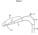
Figure 1 . Schematic exemplary illustration of a microbubble reducer, displaying an inlet (10) with a continuously increasing cross-sectional area. -
Figure 2 . Schematic exemplary illustration of a microbubble reducer according to the present invention, comprising an inlet (10) with three segments (1, 2, 3) with constant but different cross-sectional areas. -
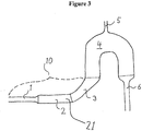
Figure 3 . Schematic exemplary illustration of a microbubble reducer, with an inlet (10) displaying two initial segments (1, 2) arranged horizontally and a third segment (3) arranged in an inclined fashion. -
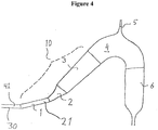
Figure 4 . Schematic exemplary illustration of a microbubble reducer, having an inlet (10) with three inclining segments (1, 2, 3) with different cross-sectional areas and with different inclination. -
Figure 5 . Schematic exemplary illustration of a microbubble reducer, wherein the microbubble reducer is arranged with components commonly utilized in a dialysis setting. -
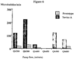
Figure 6 . Comparative graph of microbubbles/min relative various pump flows for device A and a microbubble reducer of the present disclosure. -
Figure 7 . Comparative graph of microbubbles/min relative various pump flows for device B and a microbubble reducer of the present disclosure. -
Figure 8 . Graph showing how the length of the extension channel (30) influences the removal and/or elimination of microbubbles. A longer extension channel (30) further enhances the bubble separation and removal. -
Figure 9 . Graph showing the angle of the inlet (10) influences the removal and/or elimination of microbubbles. An angle of approximately 45° relative a horizontal plane optimizes the the bubble separation and removal. -
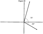
Figure 10 . Graph defining the angular interval utilized in the present disclosure. The arrows indicate the direction of the flow. -
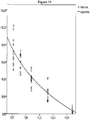
Figure 11 . Graph showing the how the number of bubbles decreases with increasing length of the lumen (21) of the inlet (10). The length designated on the x-axis (i.e. the horizontal axis) refers to the length from the start of lumen (21) to the point where the flow turns downwards towards a horizontal plane, measured along the lower rim of the lumen (21). - The present invention is concerned with a device, e. g. a venous chamber, for eliminating, removing, and/or significantly reducing bubbles of gas, with sizes down to 2.5 µm, from a flow comprising non-Newtonian fluid, and a dialysis apparatus arranged with the microbubble reducer of the invention.
- All words, terms, and abbreviations used in the present application shall be construed as having the meaning usually given to them in the relevant art, unless otherwise indicated. For clarity, some terms are however specifically defined below.
- The term "lumen" shall be understood to comprise a cavity and/or a hollow and/or a hole with a certain dimensional extension in space and/or a channel and/or a duct. The term "continuous function" shall be recognized as having the meaning usually given to it in the relevant art, i.e. a function which is continuous and differentiable and/or inte-grable over any interval. The terms "singularity" or "singularity point" shall be understood to pertain to a point where an analytical function is not defined and/or a point where a function is not differentiable (that is, essentially a point where a function stops being well-behaved in some particular way). The terms "singularity" or "singularity point" shall in this particular context be understood to describe corners, sharp angles, and/or dead spaces, meaning that a lumen that may be described by a continuous function without any singularities has substantially only smooth and/or even surfaces and is substantially completely devoid of any corners, sharp angles, and/or dead spaces (i.e. on the inside of the lumen). The term "non-Newtonian fluid" shall be understood to relate to a fluid with a viscosity that changes with changes in the velocity gradient in the fluid (i.e. the shear rate), which in turn depends on the flow velocity. Non-Newtonian fluids may for instance be blood, blood plasma, and blood substitute fluids (artifical blood and/or blood surrogates). The definition of the angles in accordance with the present disclosure, i.e. the term "from -20° to 75° relative a horizontal plane" shall be understood to relate to the whole interval from -20° to 75°, including 0° (
Figure 10 ). When said term is utilized in connection with the angle of the inlet (10), the angle of the lumen (21), and/or the angle of the extension channel (30) or the extension channel lumen (41) of the microbubble reducer of the present disclosure, it shall be understood that said parts may be arranged with an inclination of ≤ 0°, an inclination of ≥ 0°, as well as completely/substantially horizontal, that is with an angle substantially equal to 0°. The person skilled in the art naturally immediately recognizes that a horizontal arrangement of the any component of the device is within the scope of the definition of the angular interval. The term "flow passes not more than one or two other devices prior to entry into a patient" is clear and unambiguous for the skilled person and shall be understood to describe that not more than one or two other types of medicine technology devices (for instance a security device, and/or a filter) are placed between the micro bubble reducer of the present invention and a patient that is receiving the flow of non-Newtonian fluid from which the bubbles of gas have been removed, eliminated, and/or reduced using the micro bubble reducer. - As will further be apparent from the description and the examples, the term "curved duct means" relates to a duct displaying a curved shape, preferably a substantially inverted U with curved point placed at the highest point. The terms "air", "gas", "gas bubbles", and "bubbles" shall be understood to relate to undesired gaseous components present in the blood flow. The term "horizontal plane" refers to any plane substantially parallel to the earth plane, the term "low point" refers to the lower part of device, below the high point and substantially below, before, or after the curved duct means, and the term "high point" refers to the higher part of the device, on top of or laterally arranged in relation to the curved duct means. The direction of the flow may be used to define whether an inclination is rising or falling.
- One aspect of the present invention is concerned with a device, i.e. a micro bubble reducer, for eliminating bubbles of gas from a flow comprising non-Newtonian fluid, preferably a blood flow. The device is capable of reducing bubbles of various sizes but the fact that it has the capacity to eliminate so called microbubbles from a flow comprising non-Newtonian fluid results in significantly improved properties from a clinical perspective. The microbubble reducer may be arranged so that said flow passes not more than one or two other devices prior to entry into a patient, and the microbubble reducer comprises an inlet (10), at a low point, a curved duct means (4), said curved duct means comprising a gas outlet (5) at a high point, an outlet (6) at a low point, and a lumen (21) that runs through said inlet (10), said curved duct means (4), said gas outlet (5), and said outlet (6). The lumen (21) of the microbubble reducer exhibits an increasing cross-sectional area when running through the inlet (10) towards to curved duct means (4), and, further, has a length of at least 2 cm. Moreover, the lumen (21) of the inlet (10) is arranged with an angle of between 35° and 55° relative a horizontal plane.
- The increasing cross-sectional area along the inlet (10) towards the curve duct means (4) results in a decreased velocity of the blood flow, mediating ascent and thereby separation of gas bubbles present in the flow. At the high point of the curved duct means (4), the separated gas is removed from the device through a gas outlet (5), before the non-Newtonian fluid is conveyed through the outlet (6) further in the venous direction.
- The non-Newtonian fluid is introduced into the system through an inlet (10). The inlet (10) is arranged with an angle relative a horizontal plane, with the purpose of distributing any gas bubbles present in the non-Newtonian fluid to the upper part of the flow. For bubbles displaying small diameters, this is most easily achieved at a high shear rate when the viscosity of the blood is lower. The lumen (21) of the inlet (10) of the present invention has an increasing cross-sectional area in the venous direction, i. e. along the flow, with implications such as decreased flow velocity, fluid decompression, and, upon oversaturation, further upward distribution of the gases and/or gas bubbles present. The length of the inlet (10), and thereby of the lumen (21), can be modified in order to influence the separation of the gas bubbles, e.g. a longer inlet facilitating ascent of gas bubbles. After having passed the inlet, the non-Newtonian flow reaches the curved duct means (4), where gas bubbles are removed through the gas outlet (5), substantially arranged at the high point of the curved duct means (4). The upper part of the device, i.e. the curved duct means (4), enables bubble fusion, creating larger bubbles for facilitated removal through the gas outlet (5). The gas outlet (5) can be constructed in numerous ways, according to the preferred embodiments of the skilled person. Subsequently, the non-Newtonian fluid, with potentially hazardous gas bubbles removed, returns to the patient through the outlet (6). Taken together, the physical characteristics of the device mediate separation of both relatively large bubbles and microbubbles, reducing the risk of adverse events occurring in patients undergoing renal replacement therapies, plasmapheresis and apheresis, hemoperfusion, plasma filtration, or similar techniques (i. e. extracorporeal blood processing with venous infusion), including infusion therapies.
- The inclination and the expanding cross-sectional area of the lumen (21) of the inlet (10) results in facilitated bubble ascent, and the absence of corners and angles results in a laminar flow without disturbances. The resultant force between the blood flow and the buoyant force of the gas bubbles constantly directs the bubbles to the upper surface of the tube, except after the curved duct means (4), resulting in a distinct advantage relative devices currently employed within the art.
- Numerous parameters affect the flow of non-Newtonian fluids, notably blood, making the dialysis process highly complex and difficult to control. A small cross-sectional area results in a higher flow velocity and a higher shear rate, and, in blood, a lower viscosity. Additionally, water is removed, with varying velocity, during the process, with the implication that the blood being returned to the patient through the venous part of the tubing has an abnormally high erythrocyte concentration, resulting in an anomalously high viscosity. Furthermore, the blood flow is highly variable, depending on factors such as the prescribed treatment and the blood vessel access, adding additional dimensions of complexity to the dialysis process. Hence, optimizing the arrangement and the characteristics of the dialysis tubing is pivotal for efficient air removal and minimized coagulation in fluids of varying viscosity.
- The fact that the device is completely devoid of any sharp angles, corners and/or dead space imply significant advantages in terms of reduced disturbance and reduced eddy formation, as well as absence of dead spaces and reduction of slow-flowing fluid, in particular blood, improving separation of bubbles of all sizes, including microbubbles, as well as inhibiting coagulation processes, which are commonly encountered problems associated with numerous other devices for gas separation. Furthermore, the combination of the above features results in a laminar flow for optimized elimination of gas in the non-Newtonian flow. In accordance with one embodiment of the present invention, the running and/or the passage of the lumen (21) through the inlet (10), through the curved duct means (4), through the gas outlet (5), and through the outlet (6) may be described by at least one continuous function without singularities, i.e. the lumen (21) does not have any sharp angles, corners, or dead spaces where the flow becomes slow, or even substantially motionless and/or stationary.
- In order to minimize the amount of blood outside the body at any one time during treatment, dialysis devices ought to be as small as possible. Efficient removal of potentially detrimental air in the system is naturally pivotal, wherefore optimized physical properties, in accordance with the present invention, are crucial.
- In one aspect, the curved duct means (4) is in the form of a substantially inverted U. The U chamber is arranged with exclusively smooth transitions in order to further promote a laminar flow without any disturbances. The tubing component, i.e. the lumen (21) and/or (41) as per below, of the present invention preferably has a substantially circular cross-sectional area. For instance, as per the present disclosure, an oval lumen/tubing (i. e. a lumen/tubing having two different radii) with a vertical radius exceeding its horizontal radius would induce a higher shear rate, a desirable feature at certain blood concentrations. Additionally, in accordance with the present disclosure, the lumen/tubing can display different cross-sectional shapes along for instance the inlet, e. g. an initial oval shape followed by a substantially spherical shape, or vice versa. Furthermore, both different segments displaying different cross-sectional shapes and different shapes together with continuous transitions lie within the scope of the present invention.
- As per one aspect, the lumen (21) of the inlet (10) may have a length of at least 2 cm, of at least 3 centimeter, of at least 4 cm, of at least 5 cm, of at least 10 cm, of at least 15 cm, of at least 20 cm, of at least 25 cm, of at least 30 cm, of at least 35 cm, of at least 40 cm, of at least 45 cm, of at least 50 cm, of at least 55 cm, of at least 60 cm, or of at least 1 m.
Figure 11 shows hos the bubble removal increased with increasing length of the lumen (21) of the inlet (10), i.e. the longer the lumen (21) the more efficient is the bubble removal/elimination. - According to a further aspect, the microbubble reducer may further comprise an extension channel (30) comprising a lumen (41), wherein said lumen (41) of said extension channel (30) is arranged to empty into and/or transit into the lumen (21) of the inlet (10) (
Figure 4 ). The extension channel (30) may have a length of at least 2 cm, of at least 3 centimeter, of at least 4 cm, of at least 5 cm, of at least 10 cm, of at least 15 cm, of at least 20 cm, of at least 25 cm, of at least 30 cm, of at least 35 cm, of at least 40 cm, of at least 45 cm, of at least 50 cm, of at least 55 cm, of at least 60 cm, or of at least 1 m.Figure 8 clearly illustrates how the length of the extension channel (30) contributes to enhanced removal and/or elimination of bubbles of different sizes. - Further, as per another aspect, the extension channel (30) may be arranged with an angle of between -20° and 75° relative a horizontal plane, that is including 0° (the extension channel (30) may thus be horizontally arranged), in order to distribute the gas bubbles along the upper part of the flow.
- In accordance with yet another aspect, the distance from the start of the inlet (10) to the highest point of the lumen (21) of the curved duct means (4) may be at least 3 centimeter, of at least 4 cm, of at least 5 cm, of at least 10 cm, of at least 15 cm, of at least 20 cm, of at least 25 cm, of at least 30 cm, of at least 35 cm, of at least 40 cm, of at least 45 cm, of at least 50 cm, of at least 55 cm, of at least 60 cm, or of at least 1 m. The distance from the start of the inlet (10) to the highest point of the lumen (21) of the curved duct means (4) shall be understood to relate to the distance from a central point in a cross-section of the lumen (21) at the start of the inlet (10) to the highest point of the lumen (21) of the curved duct means (4).
- According to a further aspect, the inlet may have an angle of between 35° to 55° relative a horizontal plane, preferably approximately 45° relative a horizontal plane, in order to avoid bubble adherence and instead facilitate upward bubble migration in the microbubble reducer (i. e. to promote removal of gas bubbles and to avoid re-mixing of gas bubbles that have ascended to the top into the fluid). Additionally, the inlet (10) may display increasing cross-sectional area towards the curved duct means, arranged so as to increase in a segment-by-segment (1, 2, and 3 in
Figures 2-5 ) fashion. - The increasing cross-sectional area of the lumen (21) of the inlet (10) results, as above-mentioned, in a decrease in flow velocity, but it furthermore reduces the pressure of the fluid allowing small bubbles present in the blood to expand and rise, augmenting the separating effect. As per another disclosure, the lumen (21) of the inlet (10) is arranged with at least two segments, wherein each one of said segments has an angle of between -20° and 75° relative horizontal plane, preferably between 0° and 75°, more preferably between 35° to 55°, and most preferably approximately 45° relative a horizontal plane, in order to optimize bubble separation. A horizontal arrangement, i.e. 0°, also falls within the scope of the present disclosure.
-
Figure 1 represents a microbubble reducer with continuously increasing cross-sectional area of the lumen (21) of the inlet (10), where the blood flow enters the microbubble reducer through segment (1) and continues upwards through segment (2) and (3). The increasing area and the inclination of the inlet relative the horizontal plane facilitate the separation of gas bubbles of all sizes. The blood is further conveyed to the curved duct means (4), where gas bubbles are removed through the gas outlet (5), before it is returned to the patient through the outlet (6). The segments infigure 1 are naturally primarily for illustrative purposes and shall not be considered as limiting the device, i.e. the microbubble reducer, in any way. Additionally, as per one alternative, the lumen (21) of the inlet (10) is not linear but wherein its shape can be described for instance by an exponential function or a logarithm function, or additional shapes mutatis mutandis. A lumen (21) of an inlet (10) displaying continuously increasing cross-sectional area has inherent advantages associated with aspects such as ease of manufacture and facilitated post-production modifications. -
Figure 2 represents a microbubble reducer according to the invention, where the lumen (21) of the inlet (10) is comprised of three segments with different but constant intra-segment cross-sectional areas, i. e. with the cross-sectional area of segment (1) being smaller than the cross-sectional area of segment (2), which in turn has a smaller cross-sectional area than segment (3). Thus, the non-Newtonian flow enters the device through segment (1), continues to segment (2) and segment (3) with concomitant reduction in flow velocity for optimized bubble separation, before it enters the curved duct means (4), where gas is removed through the gas outlet (5). Finally, the blood is returned to the patient through the outlet (6). - In one disclosure, represented by
Figure 3 , the lumen of segment (1) and segment (2) of the inlet (10) are horizontally arranged, i. e. with an angle of 0° relative a horizontal plane, exhibiting essentially constant intra-segment cross-sectional areas, with segment (2) having a larger cross-sectional area than segment (1), in order to mediate efficient gas bubble separation. After having left segment (2), the flow rises approximately 45° through segment (3), and subsequently enters the curved duct means (4). In the present disclosure, the curved duct means (4) exhibits a shape closely resembling an inverted U, with the gas outlet (5) placed on the high point of said U shape. Finally, the blood leaves the device through the outlet (6), which is essentially perpendicularly arranged relative a horizontal plane, and continues in the venous direction. - According to another disclosure, represented by
Figure 4 , the lumen of segment (1) of the inlet (10) has a lower angle relative a horizontal plane than the remaining segments of the inlet (10), as well as a smaller cross-sectional area, in order to optimize the gas separation and removal. Whereas segment (1) has a substantially constant cross-sectional area throughout its length, segment (2), which has a steeper inclination than segment (1), exhibits an increasing intra-segment cross-sectional area, leading the non-Newtonian flow, notably blood, into segment (3), and subsequently into the curved duct means (4). The gas is removed through the gas outlet (5), before the blood flow leaves the device through the outlet (6). - In one disclosure, as represented by
Figure 5 , the microbubble reducer represented byFigure 3 is arranged together with components commonly employed in a dialysis setting. The device is arranged together with the holding means (8) of the dialysis apparatus, a venous clamp (9), and a priming detector and/or a bubble detector (6). Further, the device is equipped with additional holding means (11) and (12), in order to increase the safety of the arrangement. - All of the above-identified exemplary disclosures allows for facile adjustment of the device, in order to enable use in conjunction with various types of dialysis machines, without the need for machine alteration or modification.
- The segmented inlets (10) of certain disclosures can optionally be manufactured individually, so as to enable individual modification and even substitution of a specific segment. However, as per another example of the invention, a segmented inlet of the device can be fabricated in one piece, for facilitated manufacture.
- As per another aspect, the lumen (21) of the inlet (10), the curved duct means (4), the gas outlet (5), and the outlet (6) may have a cross-sectional area of between 1 mm2 and 800 mm2.
- Further according one aspect, a first segment of the lumen (21) of the inlet (10) may have a cross-sectional area of between 1 mm2 and 30 mm2, preferably approximately 16 mm2. Additionally, a second segment of the lumen (21) of the inlet (10) may display a cross-sectional area of between 1 mm2 and 210 mm2, preferably approximately 150 mm2. In another aspect, a third segment of the lumen (21) of the inlet (10) has a cross-sectional area of between 1 mm2 and 275 mm2, preferably approximately 200 mm2. The purpose of the various segments relates to the shear stress the lumen/tubing exerts on the blood flow; accordingly, optimization of the cross-sectional area is critical.
- As per one aspect, the lumen (21) of the outlet (6) may preferably have a perpendicular arrangement relative a horizontal plane, preferably with a deviation from said perpendicular arrangement with less than 80° in any direction, more preferably with less than 45° in any direction, and most preferably with less than 20° in any direction. The preferred arrangement of the outlet (6) pertains inter alia to the usage of the device, and the connections to various types of dialysis machines.
- According to a further aspect, the microbubble reducer, i.e. the lumen (21) and when relevant the lumen (41), may be substantially completely filled with non-Newtonian liquid, notably blood, during the course of operation, in order to optimize the air removal from the blood flow. In contrast to operating procedures of the devices currently in use within the art, said device does not require a gaseous zone, resulting in facilitated handling and improved gas removal. The operator is intended to use the device filled to the top, with the fluid monitored manually or by the detector at the top, in order to optimize the bubble reduction and to minimize the blood gas/air contact to prevent clotting.
- According to one disclosure, the microbubble reducer may be arranged with at least one filter. Said filter could be arranged anywhere within the device, but preferably in, or close to, the outlet (6), in order to remove potential blood clots. Further, the device may be arranged with at least one level detector, selected from the group comprising inter alia an optical detector, an ultrasound detector, and a conductance detector, or a bubble detector on the outlet line after the device.
- As per another disclosure, the curved duct means (4) or the gas outlet (5) of the device is arranged with means to enable manual fluid level detection or fluid level monitoring with the aid of a monitoring device. Said means facilitate optimized fluid level detection, further improving the handling and safety of the device.
- In yet another aspect, the non-Newtonian fluid may be selected from the group comprising blood, blood plasma, blood substitute liquids, plasma proteins, plasma substitutes, blood substitutes, solutions of albumin and/or other plasma proteins, gelatine compositions and haemoglobin crosfumaril, as well as relatively high-viscous liquids such as dextran solutions and hydroxy ethyl starch, etc.
- In one disclosure, an additional wall is arranged in the lumen (21, 41) of the device, in order to increase the shear rate at certain flows and during certain conditions, when this is desirable. Furthermore, including an additional wall may reduce the viscosity of the blood, an interesting feature for instance at low flow rates.
- In another aspect of the invention, an apparatus comprising the device for eliminating bubbles is connected to a dialysis machine.
- A prototype developed based on the present disclosure was compared to products currently on market, device A and device B. A standardized bubble generator was employed to generate bubbles of varying size, including microbubbles, in a solution commonly used as a blood substitute within the dialysis field. The utilized solution contains dextran and albumin and has the same viscosity as normal blood.
- The solution was re-circulated from the solution-containing vessel, wherein bubbles had been produced by the bubble generator, into a dialysis tubing system of either device A or device B, or the prototype of the present disclosure, alternately. Bubbles present downstream of the venous chamber were detected and measured using a Hatteland Instrument (Royken, Norway), as previously described elsewhere. The measurements were performed alternately between the systems for each blood flow measured in order to reduce the risk of uneven bubble distribution and potential bubble variation.
- At least ten measurements were carried out for each system at the selected flow rates (200, 300, 400, 500, and 750 ml/min), and comparative statistical analysis was carried out with non-parametrical Wilcoxon paired test.
- The following data was collected based on use of a dialysis system of the type shown in
Figure 3 . The divergence between the two comparative tests derives from variations in exposure to microbubbles per minute between the different flow measurements.Table 1. Comparison between the prototype based on the present disclosure and device A. Flow (ml/min) Prototype (bubbles/min) Device A (bubbles/min) % increase P= 200 20,3 118 581,3 0,005 300 30,8 223 724 0,005 400 8,8 31,6 359,1 0,011 450 2,9 500 6,7 121 1806,5 0,005 750 18,4 71 385,9 Table 2. Comparison between the prototype based on the present disclosure and device B. Flow (ml/min) Prototype (bubbles/min) Device B (bubbles/min) % increase P= 200 0,1667 0,5833 350 0,059 300 1,7273 18,5 1071 0,005 400 7,1 37,2727 525 0,005 500 50,8 349,7 688 0,005 750 402,2 1165,9 290 0,005 - As can be seen from Table 1 and Table 2, and
Figure 6 andFigure 7 , the prototype of the present disclosure reduced the amount of microbubbles significantly compared to the leading devices on the market today. Hence, the above results indicate the substantial advantages in terms of bubble elimination and subsequent reduction of clinical consequences when utilizing the presently disclosed device.
Claims (8)
- A microbubble reducer for removing bubbles of gas from a flow comprising non-Newtonian fluid, wherein the microbubble reducer comprises an inlet (10) at a low point, a curved duct means (4) comprising a gas outlet (5) at a high point, an outlet (6) at a low point, and a lumen (21) that runs through said inlet (10), said curved duct means (4), said gas outlet (5), and said outlet (6),wherein the lumen (21) of the inlet (10) has an increasing cross-sectional area in the direction towards the curved duct means (4),wherein the lumen (21) of the inlet (10) has a length of at least 2 cm,characterized in that the lumen (21) of the inlet (10) is arranged with an angle of between 35° and 55° relative a horizontal plane, and
said lumen (21) of the inlet (10) comprises three sequentially arranged segments (1, 2, 3) with different but constant intra-segment cross-sectional areas, wherein the first segment (1) is the segment wherein said fluid enters the microbubble reducer, the second segment (2) is arranged between the first and third segments, and the third segment (3) is arranged between the second segment and the curved duct means (4), and
wherein the cross-sectional area of the first segment (1) is smaller than the cross-sectional area of the second segment (2), and the second segment (2) has smaller cross-sectional area than the third segment (3). - The microbubble reducer according to claim 1, wherein the lumen (21) of the outlet (6) has a perpendicular arrangement relative a horizontal plane.
- The microbubble reducer according to any preceding claim, wherein the running of the lumen (21) through said inlet (10), through said curved duct means (4), through said gas outlet (5), and through said outlet (6) can be described by at least one continuous function without singularities.
- The microbubble reducer according to any preceding claim, further comprising an extension channel (30) comprising a lumen (41), wherein said extension channel (30) is arranged so that the lumen (41) empties into the lumen (21) of the inlet (10), wherein said extension channel (30) has a length of at least 1 cm.
- The microbubble reducer according to claim 4, wherein the extension channel (30) is arranged with an angle of between -20° and 75° relative a horizontal plane.
- The microbubble reducer according to any preceding claim, wherein the lumen (21) of the inlet (10) is arranged with an angle of 45°.
- The microbubble reducer according to any preceding claim, wherein the non-Newtonian fluid is selected from a group comprising blood, blood plasma, and blood substitute liquids.
- An apparatus comprising the microbubble reducer according to any preceding claim, wherein the microbubble reducer is connected to a dialysis machine.
Applications Claiming Priority (3)
| Application Number | Priority Date | Filing Date | Title |
|---|---|---|---|
| SE0950521 | 2009-07-03 | ||
| US23315209P | 2009-08-12 | 2009-08-12 | |
| PCT/SE2010/050764 WO2011002410A1 (en) | 2009-07-03 | 2010-07-02 | Bubble reducer for eliminating gas bubbles from a flow |
Publications (3)
| Publication Number | Publication Date |
|---|---|
| EP2448615A1 EP2448615A1 (en) | 2012-05-09 |
| EP2448615A4 EP2448615A4 (en) | 2017-08-30 |
| EP2448615B1 true EP2448615B1 (en) | 2019-12-11 |
Family
ID=43411292
Family Applications (1)
| Application Number | Title | Priority Date | Filing Date |
|---|---|---|---|
| EP10794463.9A Active EP2448615B1 (en) | 2009-07-03 | 2010-07-02 | Bubble reducer for eliminating gas bubbles from a flow |
Country Status (5)
| Country | Link |
|---|---|
| US (1) | US8894749B2 (en) |
| EP (1) | EP2448615B1 (en) |
| IN (1) | IN2012DN00782A (en) |
| SE (1) | SE536054C2 (en) |
| WO (1) | WO2011002410A1 (en) |
Families Citing this family (6)
| Publication number | Priority date | Publication date | Assignee | Title |
|---|---|---|---|---|
| FR2977249B1 (en) * | 2011-07-01 | 2014-09-26 | Serac Group | PACKAGING INSTALLATION COMPRISING FILLING BITS EQUIPPED WITH CONNECTING DUCTING PIPES |
| JP2013188441A (en) * | 2012-03-15 | 2013-09-26 | Asahi Kasei Medical Co Ltd | Air-bleeding device for extracorporeal circulation circuit and extracorporeal circulation circuit |
| EP3367791B1 (en) * | 2015-10-29 | 2021-07-21 | Asymptote Ltd | Methods for cryopreservation |
| US10625009B2 (en) * | 2016-02-17 | 2020-04-21 | Baxter International Inc. | Airtrap, system and method for removing microbubbles from a fluid stream |
| US10391226B2 (en) | 2017-02-07 | 2019-08-27 | International Business Machines Corporation | Air bubble removal from extracorporeal blood via chemical entrapment of nitrogen |
| CN107335255B (en) * | 2017-08-18 | 2022-10-14 | 河北科瑞达仪器科技股份有限公司 | Water route bubble remove device |
Family Cites Families (9)
| Publication number | Priority date | Publication date | Assignee | Title |
|---|---|---|---|---|
| GB451905A (en) | 1934-08-06 | 1936-08-13 | Martin Schmidt | Improvements in apparatus for separating gas and/or vapour from a mixture of gas and/or vapour and liquid flowing through a tube |
| US4493705A (en) * | 1982-08-10 | 1985-01-15 | Bentley Laboratories, Inc. | Blood reservoir |
| US4863452A (en) * | 1986-02-12 | 1989-09-05 | Minntech Corporation | Venous reservoir |
| US5061236A (en) * | 1990-07-16 | 1991-10-29 | Baxter International Inc. | Venous reservoir with improved inlet configuration and integral screen for bubble removal |
| FR2673382B1 (en) * | 1991-03-01 | 1994-04-08 | Hospal Industrie | DEVICE FOR REMOVING GAS BUBBLES FROM A FLOWING LIQUID. |
| ITMO20040235A1 (en) * | 2004-09-17 | 2004-12-17 | Gambro Lundia Ab | SNAGUE ROOM FOR AN EXTRAXORPOREO CIRCUIT. |
| US7699799B2 (en) * | 2005-08-26 | 2010-04-20 | Ceeben Systems, Inc. | Ultrasonic material removal system for cardiopulmonary bypass and other applications |
| US7892332B2 (en) * | 2007-10-01 | 2011-02-22 | Baxter International Inc. | Dialysis systems having air traps with internal structures to enhance air removal |
| EP2421584B1 (en) * | 2009-04-23 | 2016-04-13 | Fresenius Medical Care Deutschland GmbH | Air separator, external functional device, blood circulatory system and treatment device |
-
2010
- 2010-07-02 US US13/381,569 patent/US8894749B2/en active Active
- 2010-07-02 WO PCT/SE2010/050764 patent/WO2011002410A1/en active Application Filing
- 2010-07-02 SE SE1050729A patent/SE536054C2/en unknown
- 2010-07-02 IN IN782DEN2012 patent/IN2012DN00782A/en unknown
- 2010-07-02 EP EP10794463.9A patent/EP2448615B1/en active Active
Non-Patent Citations (1)
| Title |
|---|
| None * |
Also Published As
| Publication number | Publication date |
|---|---|
| SE536054C2 (en) | 2013-04-16 |
| EP2448615A4 (en) | 2017-08-30 |
| EP2448615A1 (en) | 2012-05-09 |
| SE1050729A1 (en) | 2011-01-04 |
| IN2012DN00782A (en) | 2015-06-26 |
| WO2011002410A1 (en) | 2011-01-06 |
| US20120216679A1 (en) | 2012-08-30 |
| US8894749B2 (en) | 2014-11-25 |
Similar Documents
| Publication | Publication Date | Title |
|---|---|---|
| KR101099962B1 (en) | Fluid distribution module and extracorporeal blood circuit including such a module | |
| EP2448615B1 (en) | Bubble reducer for eliminating gas bubbles from a flow | |
| US20200237993A1 (en) | Airtrap, system and method for removing microbubbles from a fluid stream | |
| CN101668555B (en) | Pressure sensing device and use of the same in a connecting structure | |
| WO2016060209A1 (en) | Body fluid filtration device of hollow fiber membrane type, and method for filtrating protein solution | |
| CN101909671A (en) | Method for determining the percentage of recirculation in a fistula and/or cardiopulmonary recirculation relative to the total fistula recirculation and cardiopulmonary recirculation | |
| CN109789262A (en) | Therapeutic equipment for removing method, control and the regulating device of blood from extracorporeal blood circuit after the haemodialysis phase completes and for executing this method | |
| US20190175815A1 (en) | Venous air capture chamber | |
| EP3789059B1 (en) | Air trap chamber and extracorporeal circulation circuit | |
| US20230405296A1 (en) | Port, Rinsing Cap, Medical Treatment Apparatus, and System | |
| EP1522323A1 (en) | Device for eliminating carbon dioxide from the blood and a crrt apparatus provided with said device | |
| Ronco et al. | The extra-corporeal circuit: physical principles and monitoring | |
| JPS64937Y2 (en) |
Legal Events
| Date | Code | Title | Description |
|---|---|---|---|
| PUAI | Public reference made under article 153(3) epc to a published international application that has entered the european phase |
Free format text: ORIGINAL CODE: 0009012 |
|
| 17P | Request for examination filed |
Effective date: 20120131 |
|
| AK | Designated contracting states |
Kind code of ref document: A1 Designated state(s): AL AT BE BG CH CY CZ DE DK EE ES FI FR GB GR HR HU IE IS IT LI LT LU LV MC MK MT NL NO PL PT RO SE SI SK SM TR |
|
| DAX | Request for extension of the european patent (deleted) | ||
| RA4 | Supplementary search report drawn up and despatched (corrected) |
Effective date: 20170728 |
|
| RIC1 | Information provided on ipc code assigned before grant |
Ipc: A61M 1/36 20060101AFI20170724BHEP Ipc: B01D 19/00 20060101ALI20170724BHEP |
|
| STAA | Information on the status of an ep patent application or granted ep patent |
Free format text: STATUS: EXAMINATION IS IN PROGRESS |
|
| 17Q | First examination report despatched |
Effective date: 20180706 |
|
| GRAP | Despatch of communication of intention to grant a patent |
Free format text: ORIGINAL CODE: EPIDOSNIGR1 |
|
| STAA | Information on the status of an ep patent application or granted ep patent |
Free format text: STATUS: GRANT OF PATENT IS INTENDED |
|
| RIN1 | Information on inventor provided before grant (corrected) |
Inventor name: JOHNSSON, PER Inventor name: STEGMAYR, BERND Inventor name: FORSBERG, ULF Inventor name: STEGMAYR, CHRISTOPHER |
|
| INTG | Intention to grant announced |
Effective date: 20190716 |
|
| GRAS | Grant fee paid |
Free format text: ORIGINAL CODE: EPIDOSNIGR3 |
|
| GRAA | (expected) grant |
Free format text: ORIGINAL CODE: 0009210 |
|
| STAA | Information on the status of an ep patent application or granted ep patent |
Free format text: STATUS: THE PATENT HAS BEEN GRANTED |
|
| AK | Designated contracting states |
Kind code of ref document: B1 Designated state(s): AL AT BE BG CH CY CZ DE DK EE ES FI FR GB GR HR HU IE IS IT LI LT LU LV MC MK MT NL NO PL PT RO SE SI SK SM TR |
|
| REG | Reference to a national code |
Ref country code: GB Ref legal event code: FG4D |
|
| RIN1 | Information on inventor provided before grant (corrected) |
Inventor name: JOHNSSON, PER Inventor name: STEGMAYR, CHRISTOFER Inventor name: STEGMAYR, BERND Inventor name: FORSBERG, ULF |
|
| REG | Reference to a national code |
Ref country code: CH Ref legal event code: EP |
|
| REG | Reference to a national code |
Ref country code: AT Ref legal event code: REF Ref document number: 1211538 Country of ref document: AT Kind code of ref document: T Effective date: 20191215 |
|
| REG | Reference to a national code |
Ref country code: DE Ref legal event code: R096 Ref document number: 602010062355 Country of ref document: DE |
|
| REG | Reference to a national code |
Ref country code: IE Ref legal event code: FG4D |
|
| REG | Reference to a national code |
Ref country code: NL Ref legal event code: MP Effective date: 20191211 |
|
| REG | Reference to a national code |
Ref country code: LT Ref legal event code: MG4D |
|
| PG25 | Lapsed in a contracting state [announced via postgrant information from national office to epo] |
Ref country code: GR Free format text: LAPSE BECAUSE OF FAILURE TO SUBMIT A TRANSLATION OF THE DESCRIPTION OR TO PAY THE FEE WITHIN THE PRESCRIBED TIME-LIMIT Effective date: 20200312 Ref country code: LT Free format text: LAPSE BECAUSE OF FAILURE TO SUBMIT A TRANSLATION OF THE DESCRIPTION OR TO PAY THE FEE WITHIN THE PRESCRIBED TIME-LIMIT Effective date: 20191211 Ref country code: NO Free format text: LAPSE BECAUSE OF FAILURE TO SUBMIT A TRANSLATION OF THE DESCRIPTION OR TO PAY THE FEE WITHIN THE PRESCRIBED TIME-LIMIT Effective date: 20200311 Ref country code: BG Free format text: LAPSE BECAUSE OF FAILURE TO SUBMIT A TRANSLATION OF THE DESCRIPTION OR TO PAY THE FEE WITHIN THE PRESCRIBED TIME-LIMIT Effective date: 20200311 Ref country code: SE Free format text: LAPSE BECAUSE OF FAILURE TO SUBMIT A TRANSLATION OF THE DESCRIPTION OR TO PAY THE FEE WITHIN THE PRESCRIBED TIME-LIMIT Effective date: 20191211 Ref country code: LV Free format text: LAPSE BECAUSE OF FAILURE TO SUBMIT A TRANSLATION OF THE DESCRIPTION OR TO PAY THE FEE WITHIN THE PRESCRIBED TIME-LIMIT Effective date: 20191211 Ref country code: ES Free format text: LAPSE BECAUSE OF FAILURE TO SUBMIT A TRANSLATION OF THE DESCRIPTION OR TO PAY THE FEE WITHIN THE PRESCRIBED TIME-LIMIT Effective date: 20191211 Ref country code: FI Free format text: LAPSE BECAUSE OF FAILURE TO SUBMIT A TRANSLATION OF THE DESCRIPTION OR TO PAY THE FEE WITHIN THE PRESCRIBED TIME-LIMIT Effective date: 20191211 |
|
| PG25 | Lapsed in a contracting state [announced via postgrant information from national office to epo] |
Ref country code: HR Free format text: LAPSE BECAUSE OF FAILURE TO SUBMIT A TRANSLATION OF THE DESCRIPTION OR TO PAY THE FEE WITHIN THE PRESCRIBED TIME-LIMIT Effective date: 20191211 |
|
| PG25 | Lapsed in a contracting state [announced via postgrant information from national office to epo] |
Ref country code: AL Free format text: LAPSE BECAUSE OF FAILURE TO SUBMIT A TRANSLATION OF THE DESCRIPTION OR TO PAY THE FEE WITHIN THE PRESCRIBED TIME-LIMIT Effective date: 20191211 |
|
| PG25 | Lapsed in a contracting state [announced via postgrant information from national office to epo] |
Ref country code: PT Free format text: LAPSE BECAUSE OF FAILURE TO SUBMIT A TRANSLATION OF THE DESCRIPTION OR TO PAY THE FEE WITHIN THE PRESCRIBED TIME-LIMIT Effective date: 20200506 Ref country code: EE Free format text: LAPSE BECAUSE OF FAILURE TO SUBMIT A TRANSLATION OF THE DESCRIPTION OR TO PAY THE FEE WITHIN THE PRESCRIBED TIME-LIMIT Effective date: 20191211 Ref country code: CZ Free format text: LAPSE BECAUSE OF FAILURE TO SUBMIT A TRANSLATION OF THE DESCRIPTION OR TO PAY THE FEE WITHIN THE PRESCRIBED TIME-LIMIT Effective date: 20191211 Ref country code: NL Free format text: LAPSE BECAUSE OF FAILURE TO SUBMIT A TRANSLATION OF THE DESCRIPTION OR TO PAY THE FEE WITHIN THE PRESCRIBED TIME-LIMIT Effective date: 20191211 Ref country code: RO Free format text: LAPSE BECAUSE OF FAILURE TO SUBMIT A TRANSLATION OF THE DESCRIPTION OR TO PAY THE FEE WITHIN THE PRESCRIBED TIME-LIMIT Effective date: 20191211 |
|
| PG25 | Lapsed in a contracting state [announced via postgrant information from national office to epo] |
Ref country code: IS Free format text: LAPSE BECAUSE OF FAILURE TO SUBMIT A TRANSLATION OF THE DESCRIPTION OR TO PAY THE FEE WITHIN THE PRESCRIBED TIME-LIMIT Effective date: 20200411 Ref country code: SK Free format text: LAPSE BECAUSE OF FAILURE TO SUBMIT A TRANSLATION OF THE DESCRIPTION OR TO PAY THE FEE WITHIN THE PRESCRIBED TIME-LIMIT Effective date: 20191211 Ref country code: SM Free format text: LAPSE BECAUSE OF FAILURE TO SUBMIT A TRANSLATION OF THE DESCRIPTION OR TO PAY THE FEE WITHIN THE PRESCRIBED TIME-LIMIT Effective date: 20191211 |
|
| REG | Reference to a national code |
Ref country code: DE Ref legal event code: R097 Ref document number: 602010062355 Country of ref document: DE |
|
| REG | Reference to a national code |
Ref country code: AT Ref legal event code: MK05 Ref document number: 1211538 Country of ref document: AT Kind code of ref document: T Effective date: 20191211 |
|
| PLBE | No opposition filed within time limit |
Free format text: ORIGINAL CODE: 0009261 |
|
| STAA | Information on the status of an ep patent application or granted ep patent |
Free format text: STATUS: NO OPPOSITION FILED WITHIN TIME LIMIT |
|
| PG25 | Lapsed in a contracting state [announced via postgrant information from national office to epo] |
Ref country code: DK Free format text: LAPSE BECAUSE OF FAILURE TO SUBMIT A TRANSLATION OF THE DESCRIPTION OR TO PAY THE FEE WITHIN THE PRESCRIBED TIME-LIMIT Effective date: 20191211 |
|
| 26N | No opposition filed |
Effective date: 20200914 |
|
| PG25 | Lapsed in a contracting state [announced via postgrant information from national office to epo] |
Ref country code: AT Free format text: LAPSE BECAUSE OF FAILURE TO SUBMIT A TRANSLATION OF THE DESCRIPTION OR TO PAY THE FEE WITHIN THE PRESCRIBED TIME-LIMIT Effective date: 20191211 Ref country code: PL Free format text: LAPSE BECAUSE OF FAILURE TO SUBMIT A TRANSLATION OF THE DESCRIPTION OR TO PAY THE FEE WITHIN THE PRESCRIBED TIME-LIMIT Effective date: 20191211 Ref country code: SI Free format text: LAPSE BECAUSE OF FAILURE TO SUBMIT A TRANSLATION OF THE DESCRIPTION OR TO PAY THE FEE WITHIN THE PRESCRIBED TIME-LIMIT Effective date: 20191211 |
|
| PG25 | Lapsed in a contracting state [announced via postgrant information from national office to epo] |
Ref country code: MC Free format text: LAPSE BECAUSE OF FAILURE TO SUBMIT A TRANSLATION OF THE DESCRIPTION OR TO PAY THE FEE WITHIN THE PRESCRIBED TIME-LIMIT Effective date: 20191211 |
|
| REG | Reference to a national code |
Ref country code: CH Ref legal event code: PL |
|
| REG | Reference to a national code |
Ref country code: BE Ref legal event code: MM Effective date: 20200731 |
|
| PG25 | Lapsed in a contracting state [announced via postgrant information from national office to epo] |
Ref country code: IE Free format text: LAPSE BECAUSE OF NON-PAYMENT OF DUE FEES Effective date: 20200702 Ref country code: LI Free format text: LAPSE BECAUSE OF NON-PAYMENT OF DUE FEES Effective date: 20200731 Ref country code: CH Free format text: LAPSE BECAUSE OF NON-PAYMENT OF DUE FEES Effective date: 20200731 Ref country code: LU Free format text: LAPSE BECAUSE OF NON-PAYMENT OF DUE FEES Effective date: 20200702 |
|
| PG25 | Lapsed in a contracting state [announced via postgrant information from national office to epo] |
Ref country code: BE Free format text: LAPSE BECAUSE OF NON-PAYMENT OF DUE FEES Effective date: 20200731 |
|
| PG25 | Lapsed in a contracting state [announced via postgrant information from national office to epo] |
Ref country code: TR Free format text: LAPSE BECAUSE OF FAILURE TO SUBMIT A TRANSLATION OF THE DESCRIPTION OR TO PAY THE FEE WITHIN THE PRESCRIBED TIME-LIMIT Effective date: 20191211 Ref country code: MT Free format text: LAPSE BECAUSE OF FAILURE TO SUBMIT A TRANSLATION OF THE DESCRIPTION OR TO PAY THE FEE WITHIN THE PRESCRIBED TIME-LIMIT Effective date: 20191211 Ref country code: CY Free format text: LAPSE BECAUSE OF FAILURE TO SUBMIT A TRANSLATION OF THE DESCRIPTION OR TO PAY THE FEE WITHIN THE PRESCRIBED TIME-LIMIT Effective date: 20191211 |
|
| PG25 | Lapsed in a contracting state [announced via postgrant information from national office to epo] |
Ref country code: MK Free format text: LAPSE BECAUSE OF FAILURE TO SUBMIT A TRANSLATION OF THE DESCRIPTION OR TO PAY THE FEE WITHIN THE PRESCRIBED TIME-LIMIT Effective date: 20191211 |
|
| PGFP | Annual fee paid to national office [announced via postgrant information from national office to epo] |
Ref country code: IT Payment date: 20230620 Year of fee payment: 14 Ref country code: FR Payment date: 20230619 Year of fee payment: 14 |
|
| PGFP | Annual fee paid to national office [announced via postgrant information from national office to epo] |
Ref country code: GB Payment date: 20230707 Year of fee payment: 14 |
|
| PGFP | Annual fee paid to national office [announced via postgrant information from national office to epo] |
Ref country code: DE Payment date: 20230621 Year of fee payment: 14 |