EP2448391A2 - Positioning device for inserting pin into PCB, method and apparatus for inserting pin into PCB - Google Patents
Positioning device for inserting pin into PCB, method and apparatus for inserting pin into PCB Download PDFInfo
- Publication number
- EP2448391A2 EP2448391A2 EP11185861A EP11185861A EP2448391A2 EP 2448391 A2 EP2448391 A2 EP 2448391A2 EP 11185861 A EP11185861 A EP 11185861A EP 11185861 A EP11185861 A EP 11185861A EP 2448391 A2 EP2448391 A2 EP 2448391A2
- Authority
- EP
- European Patent Office
- Prior art keywords
- platform
- pcb
- point
- positioning
- pin
- Prior art date
- Legal status (The legal status is an assumption and is not a legal conclusion. Google has not performed a legal analysis and makes no representation as to the accuracy of the status listed.)
- Withdrawn
Links
Images
Classifications
-
- H—ELECTRICITY
- H05—ELECTRIC TECHNIQUES NOT OTHERWISE PROVIDED FOR
- H05K—PRINTED CIRCUITS; CASINGS OR CONSTRUCTIONAL DETAILS OF ELECTRIC APPARATUS; MANUFACTURE OF ASSEMBLAGES OF ELECTRICAL COMPONENTS
- H05K13/00—Apparatus or processes specially adapted for manufacturing or adjusting assemblages of electric components
- H05K13/0015—Orientation; Alignment; Positioning
-
- H—ELECTRICITY
- H05—ELECTRIC TECHNIQUES NOT OTHERWISE PROVIDED FOR
- H05K—PRINTED CIRCUITS; CASINGS OR CONSTRUCTIONAL DETAILS OF ELECTRIC APPARATUS; MANUFACTURE OF ASSEMBLAGES OF ELECTRICAL COMPONENTS
- H05K13/00—Apparatus or processes specially adapted for manufacturing or adjusting assemblages of electric components
- H05K13/0061—Tools for holding the circuit boards during processing; handling transport of printed circuit boards
- H05K13/0069—Holders for printed circuit boards
-
- Y—GENERAL TAGGING OF NEW TECHNOLOGICAL DEVELOPMENTS; GENERAL TAGGING OF CROSS-SECTIONAL TECHNOLOGIES SPANNING OVER SEVERAL SECTIONS OF THE IPC; TECHNICAL SUBJECTS COVERED BY FORMER USPC CROSS-REFERENCE ART COLLECTIONS [XRACs] AND DIGESTS
- Y10—TECHNICAL SUBJECTS COVERED BY FORMER USPC
- Y10T—TECHNICAL SUBJECTS COVERED BY FORMER US CLASSIFICATION
- Y10T29/00—Metal working
- Y10T29/49—Method of mechanical manufacture
- Y10T29/49002—Electrical device making
- Y10T29/49117—Conductor or circuit manufacturing
- Y10T29/49124—On flat or curved insulated base, e.g., printed circuit, etc.
- Y10T29/4913—Assembling to base an electrical component, e.g., capacitor, etc.
Definitions
- the present invention relates generally to pin insertion into a PCB, particularly, to a positioning device for inserting a pin into a PCB, and method and apparatus for inserting a pin into a PCB at a fixed insertion point by using a pin insertion machine.
- a servo motor or a stepping motor is typically used to drive an X-Y platform, on which the PCB is arranged, so as to position the PCB in a proper location. Pins are then inserted into holes formed in the PCB by the pin insertion machine.
- a complicated control system is employed to control the servo motor or the stepping motor, which in turn moves the X-Y platform with the PCB mounted thereon to position the PCB.
- Such a method of positioning the PCB is complicated and causes high cost.
- the present invention is provided to overcome or alleviate at least one aspect of the above mentioned disadvantages.
- the embodiments described below disclose a positioning device for use with a pin insertion machine for inserting a pin into a PCB.
- the positioning device can comprise an X-Y platform for supporting a PCB to be inserted.
- the X-Y platform has a positioning point.
- the positioning device also comprises a reference platform for supporting a reference template.
- the X-Y platform and the reference platform are joined with each other through an x-axis guide rail and a y-axis guide rail.
- the positioning point on the X-Y platform is moveable relative to the reference platform in at least one of an x-axis direction and a y-axis direction, so as to align at least one first insertion holes on the PCB with a fixed insertion point of a pin insertion machine.
- a positioning device for inserting a pin into a PCB comprises: an X-Y platform, a PCB to be inserted being located on the X-Y platform and provided with at least one first insertion hole, and the X-Y platform being provided with a positioning point; and a reference platform, a reference template being located on the reference platform and provided with at least one reference point corresponding to the at least first insertion hole respectively.
- the X-Y platform comprises an x-axis guide rail and a y-axis guide rail so that the positioning point on the X-Y platform is adapted to be moved with respect to the reference template in an x-axis direction and/or a y-axis direction to be aligned with the at least one reference point on the reference template.
- the positioning point is moved to a position aligned with one reference point, one corresponding first insertion hole on the PCB to be inserted is aligned with a fixed insertion point for a pin insertion machine.
- the reference template is a reference PCB whose structure is the same as that of the PCB to be inserted and which includes at least one second insertion hole each forming one reference point.
- the X-Y platform is provided with a positioning member having an elongated element, wherein a tip end of the elongated member is adapted to be extended into the second insertion hole on the reference PCB, and the tip end of the elongated member is formed as the positioning point.
- the positioning device further comprises a positioning reference point, wherein the PCB to be inserted is located in a plane defined by a first plane right-angle coordinate whose coordinate origin is the fixed insertion point; and the reference PCB is located in a plane defined by a second plane right-angle coordinate whose coordinate origin is the positioning reference point, the x-axis of the second plane right-angle coordinate is in parallel with or coincides with the x-axis of the first plane right-angle coordinate, and an initial position of the positioning point is aligned with the positioning reference point. For example, the initial position of the positioning point is right above the positioning reference point.
- the X-Y platform can be provided with a first fixing member for removably fixing the PCB to be inserted to the X-Y platform.
- the reference platform is provided with a second fixing member for removably fixing the reference PCB to the reference platform.
- the X-Y platform is provided with a platform handle by means of which the X-Y platform is adapted to be moved relative to the reference platform by an operator.
- a method for inserting a pin into a PCB at a fixed insertion point by using a pin insertion machine.
- the method can comprise the following steps: (1) positioning a PCB to be inserted to an X-Y platform, wherein the PCB to be inserted is provided with at least one first insertion hole, and the X-Y platform is provided with a positioning point; (2) positioning a reference template to a reference platform, wherein the reference template is provided with at least one reference point corresponding to the at least one first insertion hole respectively; (3) moving the X-Y platform with respect to the reference platform so that the positioning point is moved to a position aligned with one reference point, and one corresponding first insertion hole on the PCB to be inserted is aligned with the fixed insertion point; (4) inserting one pin into the one first insertion hole on the PCB to be inserted aligned with the fixed insertion point by means of the pin insertion machine.
- the reference template is a reference PCB whose structure is the same as that of the PCB to be inserted and which includes at least one second insertion hole each forming one reference point.
- the X-Y platform is provided with a positioning member having an elongated element, wherein a tip end of the elongated member is adapted to be extended into the second insertion hole, and the tip end of the elongated member is formed as the positioning point
- the above step (3) further comprises the step of extending the tip end of the elongated member into the one second insertion hole, when the X-Y platform is moved with respect to the reference platform so that the positioning point is moved to the position aligned with one reference point. For example, the positioning point is moved to the position right above one reference point.
- the above method can further comprise the following step: (5) after the one pin is inserted into the one first insertion hole on the PCB to be aligned with (e.g., right above) the fixed insertion point by means of the pin insertion machine, the tip end of the elongated member is retracted from the one second insertion hole.
- the X-Y platform is moved manually in the step (3).
- an apparatus for inserting a pin into a PCB comprises the above positioning device and the pin insertion machine for inserting the pin into the PCB fixed to the X-Y platform.
- the positioning device 100 for inserting a pin into a PCB according to an exemplary embodiment of the present invention will be described.
- the positioning device 100 comprises: an X-Y platform 11, a PCB 10 to be inserted being supported on the X-Y platform 11 and provided with at least one first insertion hole 1, and the X-Y platform 11 being provided with a positioning point 2; and a reference platform 21, a reference template 20 being supported on the reference platform 21 and provided with at least one reference point 3 corresponding to the at least first insertion hole 1.
- the X-Y platform 11 comprises an x-axis guide rail 30 and a y-axis guide rail 40 so that the positioning point 2 on the X-Y platform 11 is adapted to be moved with respect to the reference template 20 in an x-axis direction and/or a y-axis direction to be aligned with (e.g., right above) each of the at least one reference point 3 on the reference template 20.
- the positioning point 2 is moved to a position aligned with (e.g., right above) one reference point 3, one corresponding first insertion hole 1 on the PCB 10 to be inserted is located aligned with (e.g., right above) a fixed insertion point 4 for a pin insertion machine (not shown).
- the fixed insertion point 4 herein is right below an insertion head of the pin insertion machine.
- the relative position relation between the X-Y platform 11 and the reference platform 21 shown in Figs. 1-3 is for illustration rather than for limitation.
- the reference platform 21 can be provided at a left side, a right side or an upper side of the X-Y platform 11, and accordingly, the position of the fixing point 2 is changed correspondingly.
- the fixed insertion point 4 is at a bottom left corner of the PCB 10 to be inserted, and the positioning point 2 is at a top right corner of the reference template 20.
- the positioning point 2 can be at a bottom left corner of the reference template 20.
- the X-Y platform 11 and the reference platform 21 can be spaced from each other with a greater distance instead of being adjacent to each other as shown in Figs. 1-3 .
- the above is only for illustration, and the X-Y platform 11 and the reference platform 21 can be arranged in other different manners based on the inventive concept of the present invention.
- positioning point 2 can be formed integrally with the X-Y platform 11, or be directly or indirectly connected to the X-Y platform 11.
- the reference template 20 herein can be formed as a plate arranged on the reference platform 21.
- the reference plate 20 can form the surface of the reference platform 21.
- the reference point 3 can be provided, and the reference point 3 can be formed as a mark, for instance, a circular point, a recess, or a hole.
- a different reference template 20 can be used and/or different reference points on the reference template 20 are used.
- the reference point 3 has the same structure as that of the first insertion hole 1.
- the reference point 3 can be formed as a spherical recess, a conical hole, a cylindrical hole or the like.
- the reference template 20 can be a reference PCB having the same structure as that of the PCB 10 to be inserted and including at least one second insertion hole. Such second insertion hole can be used as a reference point 3.
- One of the PCB 10 to be inserted and reference PCB 20 can be used as the reference template (e.g., the reference template 20 can be another PCB that is the same as the PCB 10).
- the PCB used as the reference template can have different orientation on the reference platform 21.
- the reference template 20 can be a customized template made of a metal material or other materials.
- the X-Y platform 11 is provided with a positioning member 5 having an elongated element 6.
- the elongated member 6 has a tip end 8 adapted to be extended into the second insertion hole (or the reference point 3) on the reference PCB 20.
- the tip end 8 of the elongated member 6 can be formed as the positioning point 2.
- the positioning device 100 further comprises a positioning reference point 7, which can be provided on the reference platform 21 or other position fixed with respect to the reference platform 21.
- the PCB 10 is positioned in a plane defined by a first plane of right-angle coordinate (a first XY plane) having its coordinate origin at the fixed insertion point 4.
- the reference PCB 20 is positioned in a plane defined by a second plane of right-angle coordinate (a second XY plane) having its coordinate origin at the positioning reference point 7.
- the x-axis of the second plane o fright-angle coordinate is parallel with or coincides with the x-axis of the first plane of right-angle coordinate.
- the initial position of the positioning point 2 is aligned with the positioning reference point 7.
- the positioning reference point 7 is positioned dependent on the relative position between the X-Y platform 11 and the reference platform 21, the position of the reference PCB 20 on the reference platform 21, the position of the PCB 10 to be inserted on the X-Y platform 11, so that the position of any point on the PCB 10 with respect to the insertion point 4 (x-axis distance and y-axis distance) corresponds to the position of a corresponding point on the reference PCB 20 with respect to the position of the positioning point 2 (x-axis distance and the y-axis distance).
- the coordinates of point A on the PCB 10 are (a, b) relative to the insertion point 4 as the coordinate origin.
- the coordinates of the corresponding point A' on the reference PCB 20 are also (a, b) with respect to the positioning point 2 as the coordinate origin.
- point A on the PCB 10 is also moved left by a distance a and moved downwards by a distance b to arrive at the insertion point 4.
- the X-Y platform 11 is provided with a first fixing member 14 for removably fixing the PCB 10 to the X-Y platform 11.
- the reference platform 21 is provided with a second fixing member 24 for removably fixing or retaining the reference PCB 20 on the reference platform 21.
- the first fixing member 14 includes a spring 15 and a locking tongue 16 biased by the spring 15.
- the locking tongue 16 is capable of elastically biasing the PCB 10 to fix the PCB 10 at its position.
- the structure of the second fixing member 24 can be different from that of the first fixing member 14.
- the X-Y platform 11 is provided with a handle 50, for use by an operator to move the X-Y platform 11 relative to the reference platform 21.
- the handle 50 in Figs. 1-3 is only for illustration and can have other different structures. Additionally, the handle and the positioning point or the positioning member 5 can be different position relations. For example, the positioning point 2 can be provided directly to the handle 50.
- a light emitting device can be provided on the insertion head of the pin insertion machine to emit a light beam towards the fixed insertion point 4.
- the light beam emitted is preferably a colored light beam.
- a method for inserting a pin into a PCB at a fixed insertion point 4 by using a pin insertion machine.
- the method can comprise the following steps:
- the reference template 20 can be a reference PCB having the same structure as that of the PCB 10 and including at least one second insertion hole. Such second insertion hole can form one reference point 3.
- the X-Y platform 11 can be provided with a positioning member 5 having an elongated element 6.
- the elongated member 6 can have a tip end 8 adapted to be extended into the second insertion hole and be formed as the positioning point 2.
- the above step (3) can further comprise extending the tip end 8 of the elongated member 6 into the second insertion hole, when the X-Y platform 11 is moved relative to the reference platform 21 so that the positioning point 2 is moved to the position right above the reference point 3. This helps to fix the position of the X-Y platform or the position of the PCB 10 on the X-Y platform during the inserting operation of the pin insertion machine.
- the method further comprises step (5) of retracting the tip end 8 of the elongated member 6 from the second insertion hole, after the one pin is inserted into the first insertion hole 1 on the PCB 10 right above the fixed insertion point 4 by means of the pin insertion machine.
- step (5) of retracting the tip end 8 of the elongated member 6 from the second insertion hole, after the one pin is inserted into the first insertion hole 1 on the PCB 10 right above the fixed insertion point 4 by means of the pin insertion machine.
- an apparatus for inserting a pin into a PCB.
- the apparatus can comprise the above described positioning device 100 and the pin insertion machine for inserting the pin into the PCB 10 fixed to the X-Y platform 11.
Landscapes
- Engineering & Computer Science (AREA)
- Manufacturing & Machinery (AREA)
- Microelectronics & Electronic Packaging (AREA)
- Automatic Assembly (AREA)
- Prostheses (AREA)
- Supply And Installment Of Electrical Components (AREA)
- Conveying And Assembling Of Building Elements In Situ (AREA)
- Manipulator (AREA)
- Jigs For Machine Tools (AREA)
Abstract
Description
- This application claims the benefit of Chinese Patent Application No.
201010527418.X filed on October 28, 2010 - The present invention relates generally to pin insertion into a PCB, particularly, to a positioning device for inserting a pin into a PCB, and method and apparatus for inserting a pin into a PCB at a fixed insertion point by using a pin insertion machine.
- In the prior art, during inserting a pin into a printed circuit board (PCB) by using a pin insertion machine, a servo motor or a stepping motor is typically used to drive an X-Y platform, on which the PCB is arranged, so as to position the PCB in a proper location. Pins are then inserted into holes formed in the PCB by the pin insertion machine.
- In order to position the PCB, a complicated control system is employed to control the servo motor or the stepping motor, which in turn moves the X-Y platform with the PCB mounted thereon to position the PCB. Such a method of positioning the PCB is complicated and causes high cost.
- The present invention is provided to overcome or alleviate at least one aspect of the above mentioned disadvantages.
- The embodiments described below disclose a positioning device for use with a pin insertion machine for inserting a pin into a PCB. The positioning device can comprise an X-Y platform for supporting a PCB to be inserted. The X-Y platform has a positioning point. The positioning device also comprises a reference platform for supporting a reference template. The X-Y platform and the reference platform are joined with each other through an x-axis guide rail and a y-axis guide rail. The positioning point on the X-Y platform is moveable relative to the reference platform in at least one of an x-axis direction and a y-axis direction, so as to align at least one first insertion holes on the PCB with a fixed insertion point of a pin insertion machine.
- According to one aspect of present invention, a positioning device for inserting a pin into a PCB comprises: an X-Y platform, a PCB to be inserted being located on the X-Y platform and provided with at least one first insertion hole, and the X-Y platform being provided with a positioning point; and a reference platform, a reference template being located on the reference platform and provided with at least one reference point corresponding to the at least first insertion hole respectively. The X-Y platform comprises an x-axis guide rail and a y-axis guide rail so that the positioning point on the X-Y platform is adapted to be moved with respect to the reference template in an x-axis direction and/or a y-axis direction to be aligned with the at least one reference point on the reference template. When the positioning point is moved to a position aligned with one reference point, one corresponding first insertion hole on the PCB to be inserted is aligned with a fixed insertion point for a pin insertion machine.
- In one example of the positioning device, the reference template is a reference PCB whose structure is the same as that of the PCB to be inserted and which includes at least one second insertion hole each forming one reference point.
- In another example, the X-Y platform is provided with a positioning member having an elongated element, wherein a tip end of the elongated member is adapted to be extended into the second insertion hole on the reference PCB, and the tip end of the elongated member is formed as the positioning point.
- In the above positioning device, the positioning device further comprises a positioning reference point, wherein the PCB to be inserted is located in a plane defined by a first plane right-angle coordinate whose coordinate origin is the fixed insertion point; and the reference PCB is located in a plane defined by a second plane right-angle coordinate whose coordinate origin is the positioning reference point, the x-axis of the second plane right-angle coordinate is in parallel with or coincides with the x-axis of the first plane right-angle coordinate, and an initial position of the positioning point is aligned with the positioning reference point. For example, the initial position of the positioning point is right above the positioning reference point.
- The X-Y platform can be provided with a first fixing member for removably fixing the PCB to be inserted to the X-Y platform. The reference platform is provided with a second fixing member for removably fixing the reference PCB to the reference platform.
- In the above positioning device, the X-Y platform is provided with a platform handle by means of which the X-Y platform is adapted to be moved relative to the reference platform by an operator.
- According to another aspect of the present invention, a method is provided for inserting a pin into a PCB at a fixed insertion point by using a pin insertion machine. The method can comprise the following steps: (1) positioning a PCB to be inserted to an X-Y platform, wherein the PCB to be inserted is provided with at least one first insertion hole, and the X-Y platform is provided with a positioning point; (2) positioning a reference template to a reference platform, wherein the reference template is provided with at least one reference point corresponding to the at least one first insertion hole respectively; (3) moving the X-Y platform with respect to the reference platform so that the positioning point is moved to a position aligned with one reference point, and one corresponding first insertion hole on the PCB to be inserted is aligned with the fixed insertion point; (4) inserting one pin into the one first insertion hole on the PCB to be inserted aligned with the fixed insertion point by means of the pin insertion machine.
- In the above method, the reference template is a reference PCB whose structure is the same as that of the PCB to be inserted and which includes at least one second insertion hole each forming one reference point.
- In the above method, the X-Y platform is provided with a positioning member having an elongated element, wherein a tip end of the elongated member is adapted to be extended into the second insertion hole, and the tip end of the elongated member is formed as the positioning point, and the above step (3) further comprises the step of extending the tip end of the elongated member into the one second insertion hole, when the X-Y platform is moved with respect to the reference platform so that the positioning point is moved to the position aligned with one reference point. For example, the positioning point is moved to the position right above one reference point.
- The above method can further comprise the following step: (5) after the one pin is inserted into the one first insertion hole on the PCB to be aligned with (e.g., right above) the fixed insertion point by means of the pin insertion machine, the tip end of the elongated member is retracted from the one second insertion hole.
- By repeating the above steps (3)-(5), additional pins can be inserted into other corresponding first insertion holes on the PCB to be inserted.
- In the above method, the X-Y platform is moved manually in the step (3).
- According to still another aspect of the present invention, an apparatus for inserting a pin into a PCB is provided and comprises the above positioning device and the pin insertion machine for inserting the pin into the PCB fixed to the X-Y platform.
- These and/or other aspects and advantages of the present invention will become apparent and more readily appreciated from the following description of the embodiments, taken in conjunction with the accompanying drawings of which:
-
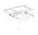
Fig. 1 is a perspective view of the positioning device for inserting a pin into a PCB according to an exemplary embodiment of the present invention; -
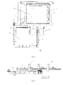
Fig. 2 is a plan view of the positioning device inFig. 1 ; -
Fig. 3 is front view of the positioning device inFig.1 ; -
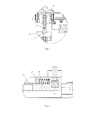
Fig. 4 is a partially enlarged sectional view of a positioning member according to an exemplary embodiment of the present invention; and -
Fig. 5 is a partially enlarged sectional view of a first fixing member according to an exemplary embodiment of the present invention. - Embodiments of the present invention will be described hereinafter in detail with reference to the attached drawings, wherein the like reference numerals refer to the like elements throughout the specification. These embodiments should not be construed as being limited to the embodiment set forth herein, rather for illustrative purpose.
- Referring to
Figs. 1-3 , thepositioning device 100 for inserting a pin into a PCB according to an exemplary embodiment of the present invention will be described. Thepositioning device 100 comprises: an X-Yplatform 11, a PCB 10 to be inserted being supported on theX-Y platform 11 and provided with at least onefirst insertion hole 1, and theX-Y platform 11 being provided with a positioning point 2; and areference platform 21, areference template 20 being supported on thereference platform 21 and provided with at least onereference point 3 corresponding to the at leastfirst insertion hole 1. TheX-Y platform 11 comprises anx-axis guide rail 30 and a y-axis guide rail 40 so that the positioning point 2 on theX-Y platform 11 is adapted to be moved with respect to thereference template 20 in an x-axis direction and/or a y-axis direction to be aligned with (e.g., right above) each of the at least onereference point 3 on thereference template 20. The positioning point 2 is moved to a position aligned with (e.g., right above) onereference point 3, one correspondingfirst insertion hole 1 on thePCB 10 to be inserted is located aligned with (e.g., right above) afixed insertion point 4 for a pin insertion machine (not shown). - The
fixed insertion point 4 herein is right below an insertion head of the pin insertion machine. - It should be noted that the relative position relation between the
X-Y platform 11 and thereference platform 21 shown inFigs. 1-3 is for illustration rather than for limitation. For example, inFig. 2 , thereference platform 21 can be provided at a left side, a right side or an upper side of theX-Y platform 11, and accordingly, the position of the fixing point 2 is changed correspondingly. For example, inFig. 2 , thefixed insertion point 4 is at a bottom left corner of thePCB 10 to be inserted, and the positioning point 2 is at a top right corner of thereference template 20. In another example where thereference platform 21 is positioned at the right side of the X-Yplatform 11, the positioning point 2 can be at a bottom left corner of thereference template 20. Further, the X-Yplatform 11 and thereference platform 21 can be spaced from each other with a greater distance instead of being adjacent to each other as shown inFigs. 1-3 . The above is only for illustration, and the X-Yplatform 11 and thereference platform 21 can be arranged in other different manners based on the inventive concept of the present invention. - In addition, one skilled in the art will appreciate that the positioning point 2 can be formed integrally with the
X-Y platform 11, or be directly or indirectly connected to theX-Y platform 11. - The
reference template 20 herein can be formed as a plate arranged on thereference platform 21. In one example, thereference plate 20 can form the surface of thereference platform 21. On thereference plate 20 thereference point 3 can be provided, and thereference point 3 can be formed as a mark, for instance, a circular point, a recess, or a hole. Fordifferent PCBs 10 to be inserted, adifferent reference template 20 can be used and/or different reference points on thereference template 20 are used. Preferably, thereference point 3 has the same structure as that of thefirst insertion hole 1. For example, thereference point 3 can be formed as a spherical recess, a conical hole, a cylindrical hole or the like. - The
reference template 20 can be a reference PCB having the same structure as that of thePCB 10 to be inserted and including at least one second insertion hole. Such second insertion hole can be used as areference point 3. One of thePCB 10 to be inserted andreference PCB 20 can be used as the reference template (e.g., thereference template 20 can be another PCB that is the same as the PCB 10). Depending on the relative position between theX-Y platform 11 and thereference platform 21, the PCB used as the reference template can have different orientation on thereference platform 21. - The
reference template 20 can be a customized template made of a metal material or other materials. - As shown in
Figs. 1-3 , theX-Y platform 11 is provided with apositioning member 5 having anelongated element 6. Theelongated member 6 has atip end 8 adapted to be extended into the second insertion hole (or the reference point 3) on thereference PCB 20. Thetip end 8 of theelongated member 6 can be formed as the positioning point 2. - As shown in
Fig. 4 , thepositioning device 100 further comprises apositioning reference point 7, which can be provided on thereference platform 21 or other position fixed with respect to thereference platform 21. As is shown inFig. 2 , thePCB 10 is positioned in a plane defined by a first plane of right-angle coordinate (a first XY plane) having its coordinate origin at the fixedinsertion point 4. Thereference PCB 20 is positioned in a plane defined by a second plane of right-angle coordinate (a second XY plane) having its coordinate origin at thepositioning reference point 7. The x-axis of the second plane o fright-angle coordinate is parallel with or coincides with the x-axis of the first plane of right-angle coordinate. - The initial position of the positioning point 2 is aligned with the
positioning reference point 7. For example, the initial position of the positioning point 2 is right above thepositioning reference point 7. Thepositioning reference point 7 is positioned dependent on the relative position between theX-Y platform 11 and thereference platform 21, the position of thereference PCB 20 on thereference platform 21, the position of thePCB 10 to be inserted on theX-Y platform 11, so that the position of any point on thePCB 10 with respect to the insertion point 4 (x-axis distance and y-axis distance) corresponds to the position of a corresponding point on thereference PCB 20 with respect to the position of the positioning point 2 (x-axis distance and the y-axis distance). - For instance, in
Fig. 2 , the coordinates of point A on thePCB 10 are (a, b) relative to theinsertion point 4 as the coordinate origin. In such as case, the coordinates of the corresponding point A' on thereference PCB 20 are also (a, b) with respect to the positioning point 2 as the coordinate origin. Thus, inFig. 2 , when the positioning point 2 on thePCB 10 is moved left by a distance a and moved downwards by a distance b to arrive at point A', point A on thePCB 10 is also moved left by a distance a and moved downwards by a distance b to arrive at theinsertion point 4. - Referring to
Figs. 1-2 , theX-Y platform 11 is provided with a first fixingmember 14 for removably fixing thePCB 10 to theX-Y platform 11. Further, thereference platform 21 is provided with a second fixingmember 24 for removably fixing or retaining thereference PCB 20 on thereference platform 21. As is shown inFig. 5 , the first fixingmember 14 includes aspring 15 and a lockingtongue 16 biased by thespring 15. The lockingtongue 16 is capable of elastically biasing thePCB 10 to fix thePCB 10 at its position. The structure of the second fixingmember 24 can be different from that of the first fixingmember 14. - As is shown in
Fig. 1 , theX-Y platform 11 is provided with ahandle 50, for use by an operator to move theX-Y platform 11 relative to thereference platform 21. Thehandle 50 inFigs. 1-3 is only for illustration and can have other different structures. Additionally, the handle and the positioning point or thepositioning member 5 can be different position relations. For example, the positioning point 2 can be provided directly to thehandle 50. - A light emitting device can be provided on the insertion head of the pin insertion machine to emit a light beam towards the fixed
insertion point 4. The light beam emitted is preferably a colored light beam. Thus, when the positioning point 2 is located right above the correspondingreference point 3, the light beam irradiates afirst insertion hole 1 where an inserting operation is desired. The light beam helps the operator to judge whether the positioning point 2 is moved to a position right above the correct reference point. - According to another aspect of the present application, a method is provided for inserting a pin into a PCB at a fixed
insertion point 4 by using a pin insertion machine. The method can comprise the following steps: - (1) positioning a
PCB 10 to be inserted on anX-Y platform 11, wherein thePCB 10 to be inserted is formed with at least onefirst insertion hole 1, and theX-Y platform 11 is formed with a positioning point 2; - (2) positioning a
reference template 20 to areference platform 21, wherein thereference template 20 is formed with at least onereference point 3 corresponding to the at least onefirst insertion hole 1 respectively; - (3) moving the
X-Y platform 11 relative to thereference platform 21 so that the positioning point 2 is moved to a position right above thereference point 3 on thereference template 20, and that one correspondingfirst insertion hole 1 on thePCB 10 is moved right above the fixedinsertion point 4; - (4) inserting a pin into the
first insertion hole 1 formed in thePCB 10 right above the fixedinsertion point 4 by means of the pin insertion machine. - As mentioned above, the
reference template 20 can be a reference PCB having the same structure as that of thePCB 10 and including at least one second insertion hole. Such second insertion hole can form onereference point 3. - The
X-Y platform 11 can be provided with apositioning member 5 having anelongated element 6. Theelongated member 6 can have atip end 8 adapted to be extended into the second insertion hole and be formed as the positioning point 2. The above step (3) can further comprise extending thetip end 8 of theelongated member 6 into the second insertion hole, when theX-Y platform 11 is moved relative to thereference platform 21 so that the positioning point 2 is moved to the position right above thereference point 3. This helps to fix the position of the X-Y platform or the position of thePCB 10 on the X-Y platform during the inserting operation of the pin insertion machine. - The method further comprises step (5) of retracting the
tip end 8 of theelongated member 6 from the second insertion hole, after the one pin is inserted into thefirst insertion hole 1 on thePCB 10 right above the fixedinsertion point 4 by means of the pin insertion machine. The above steps (3)-(5) can be repeated to insert one or more pin into other corresponding first insertion hole(s) on thePCB 10 to be inserted. - According to still another aspect of the present application, an apparatus is provided for inserting a pin into a PCB. The apparatus can comprise the above described
positioning device 100 and the pin insertion machine for inserting the pin into thePCB 10 fixed to theX-Y platform 11. - Although several exemplary embodiments have been shown and described, it would be appreciated by those skilled in the art that various changes or modifications can be made in these embodiments without departing from the principles and spirit of the disclosure, the scope of which is defined in the appended claims and their equivalents.
Claims (15)
- A positioning device (100) for use with a pin insertion machine for inserting a pin into a PCB, the positioning device comprising:an X-Y platform (11) for supporting a PCB (10) to be inserted, the X-Y platform (11) having a positioning point (2); anda reference platform (21) for supporting a reference template (20);wherein the X-Y platform (11) and the reference platform are joined with each other through an x-axis guide rail (30) and a y-axis guide rail (40), and
wherein the positioning point (2) on the X-Y platform (11) is moveable relative to the reference platform (21) in at least one of an x-axis direction and a y-axis direction, so as to align at least one first insertion holes (1) on the PCB (10) with a fixed insertion point (4) of a pin insertion machine. - The positioning device (100) according to claim 1 further comprising:a PCB (10) to be inserted, which is supported on the X-Y platform (11) and formed with at least one first insertion hole (1); anda reference template (20) supported on the reference platform (21), the reference template (20) being formed with at least one reference point (3) corresponding to the at least first insertion hole (1),wherein, when the positioning point (2) on the X-Y platform (11) moves relative to the reference platform (21) in the at least one of an x-axis direction and a y-axis direction, the positioning point (2) aligns with the at least one reference point (3) on the reference template (20), whereby the at least one first insertion hole (1) on the PCB (10) is aligned with a fixed insertion point (4) of a pin insertion machine.
- The positioning device (100) according to claim 2, wherein the reference template comprises a reference PCB having a same structure as that of the PCB (10) to be inserted and being formed with at least one second insertion hole, the at least one second insertion hole forming the reference point (3).
- The positioning device (100) according to claim 3,
wherein the X-Y platform comprises a positioning member (5) having an elongated element (6),
wherein the elongated member (6) has a tip end (8) adapted to be extended into the second insertion hole in the reference PCB, and
wherein the tip end (8) of the elongated member (6) is formed as the positioning point (2). - The positioning device (100) according to claim 3 further comprising a positioning reference point (7),
wherein the PCB (10) to be inserted is located in a plane defined by a first plane of right-angle coordinate having a coordinate origin at the fixed insertion point (4),
wherein the reference PCB is located in a plane defined by a second plane right-angle coordinate having a coordinate origin at the positioning reference point (7),
wherein the second plane of right-angle coordinate has an x-axis parallel with or co-extending with an x-axis of the first plane of right-angle coordinate, and
wherein an initial position of the positioning point (2) is aligned with the positioning reference point (7). - The positioning device (100) according to claim 2, wherein the reference platform (21) comprises a fixing member (24) for removably mounting the reference template (20) to the reference platform (21).
- The positioning device (100) according to claim 1, wherein the X-Y platform (11) is formed with a platform handle (50) for use to move the X-Y platform (11) to the reference platform (21) by an operator.
- A method for inserting a pin into a PCB at a fixed insertion point (4) by using a pin insertion machine, the method comprising the following steps:positioning a PCB (10) to be inserted on an X-Y platform (11), wherein the PCB (10) to be inserted is formed with at least one first insertion hole (1), and the X-Y platform (11) is provided with a positioning point (2);positioning a reference template (20) on a reference platform (21), wherein the reference platform (21) is formed with at least one reference point (3) corresponding to the at least one first insertion hole (1);moving the X-Y platform (11) relative to the reference platform (21) to align the positioning point (2) with the at least one reference point (3), so that the at least one first insertion hole (1) on the PCB (10) to be inserted is aligned with a fixed insertion point (4) of the pin insertion machine; andinserting a pin into the at least one first insertion hole (1) on the PCB (10) to be inserted by means of the pin insertion machine at the fixed insertion point (4).
- The method according to claim 8, wherein the reference template (20) is a reference PCB having a same structure as that of the PCB (10) to be inserted and including at least one second insertion hole, the at least one second insertion hole forming one reference point (3).
- The method according to claim 9,
wherein the X-Y platform (11) is formed with a positioning member (5) having an elongated element (6), the elongated member (6) having a tip end (8) adapted to be extended into the second insertion hole and formed as the positioning point (2), and
wherein the method further comprises extending the tip end (8) of the elongated member (6) into the at least one second insertion hole, when the X-Y platform (11) is moved relative to the reference platform (21) to align the positioning point (2) with the at least one reference point (3). - The method according to claim 10, further comprising retracting the tip end (8) of the elongated member (6) from the at least one second insertion hole, after the pin is inserted into the at least one first insertion hole (1) on the PCB (10) to be inserted.
- The method according to claim 8 further comprising inserting one or more other pins into one or more other corresponding first insertion holes on the PCB to be inserted.
- The method according to claim 8, wherein the X-Y platform is moved manually.
- An apparatus for inserting a pin into a PCB, the apparatus comprising:the positioning device according to claim 1, anda pin insertion machine for inserting the pin into a PCB fixed to the X-Y platform,wherein the pin insertion machine has a fixed insertion point (4), and
whereby, when the positioning point (2) on the X-Y platform (11) is moveable relative to the reference platform (21) in at least one of an x-axis direction and a y-axis direction, the fixed insertion point (4) can be aligned with the at least one first insertion holes (1) on the PCB (10) for pin insertion. - The apparatus according to claim 14, wherein the reference platform (21) is immovably mounted with respect to the fixed insertion point (4).
Applications Claiming Priority (1)
| Application Number | Priority Date | Filing Date | Title |
|---|---|---|---|
| CN201010527418.XA CN102457005B (en) | 2010-10-28 | 2010-10-28 | Positioning device for inserting PCB, PCB inserting method and equipment |
Publications (2)
| Publication Number | Publication Date |
|---|---|
| EP2448391A2 true EP2448391A2 (en) | 2012-05-02 |
| EP2448391A3 EP2448391A3 (en) | 2017-06-21 |
Family
ID=44863354
Family Applications (1)
| Application Number | Title | Priority Date | Filing Date |
|---|---|---|---|
| EP11185861.9A Withdrawn EP2448391A3 (en) | 2010-10-28 | 2011-10-20 | Positioning device for inserting pin into PCB, method and apparatus for inserting pin into PCB |
Country Status (3)
| Country | Link |
|---|---|
| US (1) | US9179585B2 (en) |
| EP (1) | EP2448391A3 (en) |
| CN (1) | CN102457005B (en) |
Families Citing this family (2)
| Publication number | Priority date | Publication date | Assignee | Title |
|---|---|---|---|---|
| TWI472397B (en) * | 2012-02-10 | 2015-02-11 | 中原大學 | Two - legged mobile platform structure |
| CN105598869A (en) * | 2014-10-31 | 2016-05-25 | 富泰华工业(深圳)有限公司 | Positioning device |
Family Cites Families (8)
| Publication number | Priority date | Publication date | Assignee | Title |
|---|---|---|---|---|
| US3143791A (en) * | 1962-03-21 | 1964-08-11 | United Shoe Machinery Corp | Work positioning table |
| CH610171A5 (en) * | 1976-04-02 | 1979-03-30 | Schlup G E & Co | |
| US4265013A (en) * | 1979-05-10 | 1981-05-05 | Methode Electronics, Inc. | Apparatus for driving pins into a printed circuit board and the like |
| US4610084A (en) * | 1984-05-21 | 1986-09-09 | At&T Technologies, Inc. | Method and apparatus for inserting leads into holes in substrates |
| CN201039596Y (en) * | 2007-04-20 | 2008-03-19 | 源台精密科技股份有限公司 | Printed circuit board transplanting and aligning device |
| JP4906107B2 (en) * | 2007-09-20 | 2012-03-28 | 富士機械製造株式会社 | Substrate transfer device for electronic component mounting equipment |
| JP2009278014A (en) * | 2008-05-16 | 2009-11-26 | Juki Corp | Component mounting apparatus and substrate conveying method |
| CN201504387U (en) * | 2009-09-18 | 2010-06-09 | 东莞市新泽谷机械有限公司 | Automatic vertical mechanism for conveying elements in inserting machine |
-
2010
- 2010-10-28 CN CN201010527418.XA patent/CN102457005B/en active Active
-
2011
- 2011-10-20 EP EP11185861.9A patent/EP2448391A3/en not_active Withdrawn
- 2011-10-28 US US13/283,960 patent/US9179585B2/en not_active Expired - Fee Related
Non-Patent Citations (1)
| Title |
|---|
| None |
Also Published As
| Publication number | Publication date |
|---|---|
| CN102457005B (en) | 2014-04-23 |
| EP2448391A3 (en) | 2017-06-21 |
| US9179585B2 (en) | 2015-11-03 |
| CN102457005A (en) | 2012-05-16 |
| US20120102731A1 (en) | 2012-05-03 |
Similar Documents
| Publication | Publication Date | Title |
|---|---|---|
| US10589514B2 (en) | Screen printing device having conveyance section for discharging and introducing both the screen mask and board support member | |
| JP6619019B2 (en) | Anti-substrate working system and insertion method | |
| KR102031812B1 (en) | Electronic component mounting apparatus | |
| US11304350B2 (en) | Board work machine and insertion method | |
| CN108029231B (en) | Substrate processing machine and recognition method | |
| WO2016147332A1 (en) | Recognition device | |
| US9179585B2 (en) | Positioning device for inserting pin into printed circuit broad | |
| US10820460B2 (en) | Cutting and bending device | |
| DE10300518B4 (en) | Device for loading substrates with components and method for calibrating such a device | |
| JP6648132B2 (en) | Board work machine and recognition method | |
| WO2018061207A1 (en) | Machine for performing work on substrate, and insertion method | |
| CN109661863A (en) | Identification device | |
| EP3346812A1 (en) | Operation machine | |
| US10470350B2 (en) | Work machine | |
| US11328405B2 (en) | Electronic component mounting orientation checking system and electronic component mounting orientation checking method | |
| EP3267146B1 (en) | Recognition device and recognition method | |
| CN102878900B (en) | Method and device for detecting height of pins of PCBA (printed circuit board assembly) element | |
| CN108353533B (en) | Bending device | |
| WO2018029844A1 (en) | Substrate working machine | |
| US20150382522A1 (en) | Component mounting device and component mounting method | |
| EP3684157A1 (en) | Mounting system | |
| EP3490361A1 (en) | Substrate work machine | |
| EP4025031B1 (en) | Work machine |
Legal Events
| Date | Code | Title | Description |
|---|---|---|---|
| PUAI | Public reference made under article 153(3) epc to a published international application that has entered the european phase |
Free format text: ORIGINAL CODE: 0009012 |
|
| AK | Designated contracting states |
Kind code of ref document: A2 Designated state(s): AL AT BE BG CH CY CZ DE DK EE ES FI FR GB GR HR HU IE IS IT LI LT LU LV MC MK MT NL NO PL PT RO RS SE SI SK SM TR |
|
| AX | Request for extension of the european patent |
Extension state: BA ME |
|
| PUAL | Search report despatched |
Free format text: ORIGINAL CODE: 0009013 |
|
| AK | Designated contracting states |
Kind code of ref document: A3 Designated state(s): AL AT BE BG CH CY CZ DE DK EE ES FI FR GB GR HR HU IE IS IT LI LT LU LV MC MK MT NL NO PL PT RO RS SE SI SK SM TR |
|
| AX | Request for extension of the european patent |
Extension state: BA ME |
|
| RIC1 | Information provided on ipc code assigned before grant |
Ipc: H05K 13/00 20060101AFI20170512BHEP |
|
| STAA | Information on the status of an ep patent application or granted ep patent |
Free format text: STATUS: THE APPLICATION IS DEEMED TO BE WITHDRAWN |
|
| 18D | Application deemed to be withdrawn |
Effective date: 20171222 |